Physics Jonathan Dowling. Lecture 35: MON 16 NOV Electrical Oscillations, LC Circuits, Alternating Current II
|
|
|
- Gregory Nicholson
- 6 years ago
- Views:
Transcription


1 hysics 2113 Jonathan Dowling Lecture 35: MON 16 NOV Electrical Oscillations, LC Circuits, Alternating Current II
2 Damped LCR Oscillator Ideal LC circuit without resistance: oscillations go on forever; ω = (LC) 1/2 Real circuit has resistance, dissipates energy: oscillations die out, or are damped C R L Math is complicated! Important points: Frequency of oscillator shifts away from 1. 0 U max = Q2 Rt 2C e L ω = (LC) -1/2 eak CHARGE decays with time constant = τ QLCR =2L/R For small damping, peak ENERGY decays with time constant τ ULCR = L/R U E t i m e ( s )
3 Which one of the following choices will damp oscillations in an LC circuit? a) increase the inductance b) increase the emf c) increase the circuit resistance d) increase the capacitance
4 Which one of the following choices will damp oscillations in an LC circuit? a) increase the inductance b) increase the emf c) increase the circuit resistance d) increase the capacitance
5 ( ω φ) Damped Oscillations in an RCL Circuit If we add a resistor in an RL circuit (see figure) we must modify the energy equation, because now energy is 2 being dissipated on the resistor: = i R. U = U + U = bt/2m ( t) = xme cos t +. The angular freque E B du dt 2 2 q Li du q dq di 2 + = + Li = i R 2C 2 dt C dt dt 2 2 dq di d q d q dq 1 i = = L + R + q = 0. This is the same equation as that 2 2 dt dt dt dt dt C 2 d x dx of the damped harmonics oscillator: m + b + kx = 0, which has the solution: 2 dt dt x For the damped RCL circuit the solution is: ncy k ω = m 2 b 4m 2. 2 Rt /2L 1 R ( ω + φ) The angular frequency ω 2 q( t) = Qe cos t. =. LC 4L (31-6)

6 Q q( t) / 2 Qe Rt L q( t) / 2 ( ) Rt L q t Qe cos t ( ω φ) = R ω = LC 4L 2 Q / 2 Qe Rt L The equations above describe a harmonic oscillator with an exponentially decaying amplitude Qe Rt/2 L. The angular frequency of the damped oscillator ω = 1 LC R2 4L 2 is always smaller than the angular frequency ω = 1 LC undamped oscillator. If the term R 2 4L 1 2 LC of the we can use the approximation ω ω. τ RC = RC τ RL = L / R τ RCL = 2L / R

7 R 2 4L 1 2 LC? ! ω = 1 LC R2 4L 2 1 LC = ω
 / 2 = 50%")
8 Q(t) Q(0) / 2 = 50% t(s)
 and inductor (magnetic field).")
9 Summary Capacitor and inductor combination produces an electrical oscillator, natural frequency of oscillator is ω=1/ LC Total energy in circuit is conserved: switches between capacitor (electric field) and inductor (magnetic field). If a resistor is included in the circuit, the total energy decays (is dissipated by R).

10 Alternating Current: To keep oscillations going we need to drive the circuit with an external emf that produces a current that goes back and forth. Notice that there are two frequencies involved: ω at which the circuit would oscillate naturally. The other is ω d the driving frequency at which we drive the oscillation. However, the natural oscillation usually dies off quickly (exponentially) with time. Therefore in the long run, circuits actually oscillate with the frequency at which they are driven. (All this is true for the gentleman trying to make the lady swing back and forth in the picture too).
11 Alternating Current: We have studied that a loop of wire, spinning in a constant magnetic field will have an induced emf that oscillates with time, E = E m sin(ω d t) That is, it is an AC generator. AC s are very easy to generate, they are also easy to amplify and decrease in voltage. This in turn makes them easy to send in distribution grids like the ones that power our homes. Because the interplay of AC and oscillating circuits can be quite complex, we will start by steps, studying how currents and voltages respond in various simple circuits to AC s.
12
13 31.6: Forced Oscillations:


14 31.9: The Series RLC Circuit, Resonance:
15 Example 1 : Tuning a Radio Receiver Driven RLC With EMF Antennal The inductor and capacitor in a car radio have one program at L = 1 mh & C = 3.18 pf. Which is the FM station? WRKF 89.3 What is the wavelength Of the radio wave from The tower? FM radio stations: frequency is in MHz. 1 ω = LC 1 = rad/s = rad/s f = ω 2π = Hz = 89.3 MHz


16 Example 1 : Tuning a Radio Receiver Driven RLC at Resonance With EMF Antenna

17 31.6: Forced Oscillations: In the power grid we make sure that all circuits are far away From any resonances!
, that is, they are in phase. For time dependent periodic situations it is useful to represent magnitudes using Steinmetz phasors.")
18 AC Driven Circuits: emf v R = 0 1) A Resistor: v R = emf = E m sin(ω d t) i R = v R R = E m R sin(ω d t) Charles Steinmetz Resistors behave in AC very much as in DC, current and voltage are proportional (as functions of time in the case of AC), that is, they are in phase. For time dependent periodic situations it is useful to represent magnitudes using Steinmetz phasors. These are vectors that rotate at a frequency w d, their magnitude is equal to the amplitude of the quantity in question and their projection on the vertical axis represents the instantaneous value of the quantity.
19 AC Driven Circuits: 2) Capacitors: v C = emf = E m sin(ω d t) q C = Cemf = CE m sin(ω d t) i C = dq C = ω d CE m cos(ω d t) dt i C = ω d CE m sin(ω d t ) i C = E m X sin(ω t + d 900 ) 1 where X = "reactance" C i m = E m X ω d looks like i = V R Capacitors oppose a resistance to AC (reactance) of frequency-dependent magnitude 1/ω d C (this idea is true only for maximum amplitudes, the instantaneous story is more complex).
20 AC Driven Circuits: v L = emf = E m sin(ω d t) 3) Inductors: v L = di L dt L i L = vldt L i L = E m Lω d cos(ω d t) = i L = E m X sin(ω d t 90 0 ) E m Lω d sin(ω d t 90 0 ) i m = E m X where X = Lω d Inductors oppose a resistance to AC (reactance) of frequency-dependent magnitude w d L (this idea is true only for maximum amplitudes, the instantaneous story is more complex).
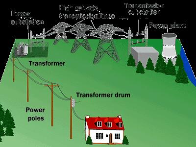
21 ower Station Transmission lines E rms =735 kv, I rms = 500 A Step-up transformer Energy Transmission Requirements Step-down transformer T 1 T 2 R = 220Ω l 110 V Home =1000 km The resistance of the power line R = ρl A. R is fixed (220 Ω in our example). Heating of power lines heat = I 2 rms R. This parameter is also fixed (55 MW in our example). ower transmitted trans = E rms I rms (368 MW in our example). In our example heat is almost 15 % of trans and is acceptable. To keep heat small we must keep I rms as low as possible. The only way to accomplish this is by increasing E rms. In our example E rms = 735 kv. To do that we need a device that can change the amplitude of any ac voltage (either increase or decrease). trans =iv = big heat =i 2 R = small Solution: Big V! (31-24)
22


23 The DC vs. AC Current Wars Thomas Edison pushed for the development of a DC power network. George Westinghouse backed Tesla s development of an AC power network. Nikola Tesla was instrumental in developing AC networks. Edison was a brute-force experimenter, but was no mathematician. AC cannot be properly understood or exploited without a substantial understanding of mathematics and mathematical physics, which Tesla possessed.
24 The Tesla Three-hase AC Transmission System The most common example is the Tesla three-phase power system used for industrial applications and for power transmission. The most obvious advantage of three phase power transmission using three wires, as compared to single phase power transmission over two wires, is that the power transmitted in the three phase system is the voltage multiplied by the current in each wire times the square root of three (approximately 1.73). The power transmitted by the single phase system is simply the voltage multiplied by the current. Thus the three phase system transmits 73% more power but uses only 50% more wire.


25 Niagara Falls and Steinmetz s Turning of the Screw Against General Electric and Edison's proposal, Westinghouse, using Tesla's AC system, won the international Niagara Falls Commission contract. Tesla s three-phase AC transmission became the World s power-grid standard. Transforming DC power from one voltage to another was difficult and expensive due to the need for a large spinning rotary converter or motorgenerator set, whereas with AC the voltage changes can be done with simple and efficient transformer coils that have no moving parts and require no maintenance. This was the key to the success of the AC system. Modern transmission grids regularly use AC voltages up to 765,000 volts.
26 The Transformer The transformer is a device that can change the voltage amplitude of any ac signal. It consists of two coils with a different number of turns wound around a common iron core. The coil on which we apply the voltage to be changed is called the " primary" and it has N turns. The transformer output appears on the second coil, which is known as the "secondary" and has N S turns. The role of the iron core is to ensure that the magnetic field lines from one coil also pass through the second. We assume that if voltage equal to V is applied across the primary then a voltage V appears on the secondary coil. We also assume that the magnetic field through both coils is equal to B and that the iron core has cross-sectional area A. The magnetic flux dφ db through the primary Φ = NBA V = = N A ( eq. 1). dt dt dφs db The flux through the secondary Φ S = NS BA VS = = NS A ( eq. 2). dt dt (31-25) S
27 V N S S = V N dφ db Φ = NBA V = = N A ( eq. 1) dt dt dφs db Φ S = NS BA VS = = NS A ( eq. 2) dt dt If we divide equation 2 by equation 1 we get: V V S db N A = = N S dt S VS V db = N N S A N N dt. NS The voltage on the secondary VS = V. N NS If NS > N > 1 VS > V, we have what is known as a " step up" transformer. N NS If NS < N < 1 VS < V, we have what is known as a " step down" transformer. N Both types of transformers are used in the transport of electric power over large distances. (31-26)
. If we divide eq. 2 with eq.")
28 I I S V N S S = V N I N = I N S S We have that: V N = V N S S V N S S = V N (eq. 1). If we close switch S in the figure we have in addition to the primary current a current I in the secondary coil. We assume that the transformer is " ideal, " S i.e., it suffers no losses due to heating. Then we have: V I = V I (eq. 2). If we divide eq. 2 with eq. 1 we get: I S = N N S I In a step-up transformer ( N > N ) we have that I < I. In a step-down transformer ( N VI V N V I V N S S = S S S S S S I N < N ) we have that I > I. S S = I N S S. I (31-27)
29 Example, Transformer:
 0.")
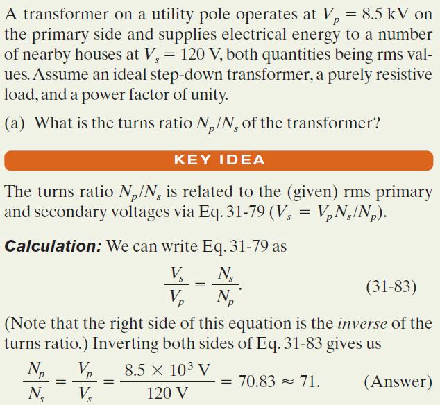
30 The ac adapter for a laptop computer contains a transformer. The input of the adapter is the 120 volts from the ac wall outlet. The output from the transformer is 20 volts. What is the turns ratio of the transformer? a) 0.17 b) 6 c) 100 d) This cannot be determined without knowing how many turns one of the coils in the transformer has.
31 The ac adapter for a laptop computer contains a transformer. The input of the adapter is the 120 volts from the ac wall outlet. The output from the transformer is 20 volts. What is the turns ratio of the transformer? a) 0.17 b) 6 c) 100 d) This cannot be determined without knowing how many turns one of the coils in the transformer has.
An induced emf is the negative of a changing magnetic field. Similarly, a self-induced emf would be found by
 This is a study guide for Exam 4. You are expected to understand and be able to answer mathematical questions on the following topics. Chapter 32 Self-Induction and Induction While a battery creates an
Physics for Scientists & Engineers 2 2 = 1 LC. Review ( ) Review (2) Review (3) e! Rt. cos "t + # ( ) q = q max. Spring Semester 2005 Lecture 30 U E
 Review (2) Review (3) e! Rt. cos t + # ( ) q = q max. Spring Semester 2005 Lecture 30 U E") Review hysics for Scientists & Engineers Spring Semester 005 Lecture 30! If we have a single loop RLC circuit, the charge in the circuit as a function of time is given by! Where q = q max e! Rt L cos "t
Review hysics for Scientists & Engineers Spring Semester 005 Lecture 30! If we have a single loop RLC circuit, the charge in the circuit as a function of time is given by! Where q = q max e! Rt L cos "t
Electromagnetic Oscillations and Currents. March 23, 2014 Chapter 30 1
 Electromagnetic Oscillations and Currents March 23, 2014 Chapter 30 1 Driven LC Circuit! The voltage V can be thought of as the projection of the vertical axis of the phasor V m representing the time-varying
Look over Chapter 31 sections 1-4, 6, 8, 9, 10, 11 Examples 1-8. Look over Chapter 21 sections Examples PHYS 2212 PHYS 1112
 PHYS 2212 Look over Chapter 31 sections 1-4, 6, 8, 9, 10, 11 Examples 1-8 PHYS 1112 Look over Chapter 21 sections 11-14 Examples 16-18 Good Things To Know 1) How AC generators work. 2) How to find the
CHAPTER 6: ALTERNATING CURRENT
 CHAPTER 6: ALTERNATING CURRENT PSPM II 2005/2006 NO. 12(C) 12. (c) An ac generator with rms voltage 240 V is connected to a RC circuit. The rms current in the circuit is 1.5 A and leads the voltage by
Chapter 33. Alternating Current Circuits
 Chapter 33 Alternating Current Circuits Alternating Current Circuits Electrical appliances in the house use alternating current (AC) circuits. If an AC source applies an alternating voltage to a series
Alternating current circuits- Series RLC circuits
 FISI30 Física Universitaria II Professor J.. ersosimo hapter 8 Alternating current circuits- Series circuits 8- Introduction A loop rotated in a magnetic field produces a sinusoidal voltage and current.
Electricity & Optics
 Physics 24100 Electricity & Optics Lecture 19 Chapter 29 sec. 1,2,5 Fall 2017 Semester Professor Koltick Series and Parallel R and L Resistors and inductors in series: R series = R 1 + R 2 L series = L
Chapter 30 Inductance, Electromagnetic. Copyright 2009 Pearson Education, Inc.
 Chapter 30 Inductance, Electromagnetic Oscillations, and AC Circuits 30-7 AC Circuits with AC Source Resistors, capacitors, and inductors have different phase relationships between current and voltage
Physics 132 Quiz # 23
 Name (please (please print) print) Physics 132 Quiz # 23 I. I. The The current in in an an ac ac circuit is is represented by by a phasor.the value of of the the current at at some time time t t is is
AC Circuits. Nikola Tesla
 AC Circuits Nikola Tesla 1856-1943 Mar 26, 2012 Alternating Current Circuits Electrical appliances in the house use alternating current (AC) circuits. If an AC source applies an alternating voltage of
Chapter 6: Alternating Current. An alternating current is an current that reverses its direction at regular intervals.
 Chapter 6: Alternating Current An alternating current is an current that reverses its direction at regular intervals. Overview Alternating Current Phasor Diagram Sinusoidal Waveform A.C. Through a Resistor
AC Circuit. What is alternating current? What is an AC circuit?
 Chapter 21 Alternating Current Circuits and Electromagnetic Waves 1. Alternating Current 2. Resistor in an AC circuit 3. Capacitor in an AC circuit 4. Inductor in an AC circuit 5. RLC series circuit 6.
#8A RLC Circuits: Free Oscillations
 #8A RL ircuits: Free Oscillations Goals In this lab we investigate the properties of a series RL circuit. Such circuits are interesting, not only for there widespread application in electrical devices,
Class XII Chapter 7 Alternating Current Physics
 Question 7.1: A 100 Ω resistor is connected to a 220 V, 50 Hz ac supply. (a) What is the rms value of current in the circuit? (b) What is the net power consumed over a full cycle? Resistance of the resistor,
Alternating Current. Slide 1 / 69. Slide 2 / 69. Slide 3 / 69. Topics to be covered. Sources of Alternating EMF. Sources of alternating EMF
 Slide 1 / 69 lternating urrent Sources of alternating EMF Transformers ircuits and Impedance Topics to be covered Slide 2 / 69 LR Series ircuits Resonance in ircuit Oscillations Sources of lternating EMF
Alternating Current. Slide 2 / 69. Slide 1 / 69. Slide 3 / 69. Slide 4 / 69. Slide 6 / 69. Slide 5 / 69. Topics to be covered
 Slide 1 / 69 lternating urrent Sources of alternating EMF ircuits and Impedance Slide 2 / 69 Topics to be covered LR Series ircuits Resonance in ircuit Oscillations Slide 3 / 69 Sources of lternating EMF
AC Circuits INTRODUCTION DISCUSSION OF PRINCIPLES. Resistance in an AC Circuit
 AC Circuits INTRODUCTION The study of alternating current 1 (AC) in physics is very important as it has practical applications in our daily lives. As the name implies, the current and voltage change directions
AP Physics C. Alternating Current. Chapter Problems. Sources of Alternating EMF
 AP Physics C Alternating Current Chapter Problems Sources of Alternating EMF 1. A 10 cm diameter loop of wire is oriented perpendicular to a 2.5 T magnetic field. What is the magnetic flux through the
Chapter 31 Alternating Current
 Chapter 31 Alternating Current In this chapter we will learn how resistors, inductors, and capacitors behave in circuits with sinusoidally vary voltages and currents. We will define the relationship between
Chapter 33. Alternating Current Circuits
 Chapter 33 Alternating Current Circuits C HAP T E O UTLI N E 33 1 AC Sources 33 2 esistors in an AC Circuit 33 3 Inductors in an AC Circuit 33 4 Capacitors in an AC Circuit 33 5 The L Series Circuit 33
Lecture Outline Chapter 24. Physics, 4 th Edition James S. Walker. Copyright 2010 Pearson Education, Inc.
 Lecture Outline Chapter 24 Physics, 4 th Edition James S. Walker Chapter 24 Alternating-Current Circuits Units of Chapter 24 Alternating Voltages and Currents Capacitors in AC Circuits RC Circuits Inductors
ELECTROMAGNETIC INDUCTION AND ALTERNATING CURRENT (Assignment)
") ELECTROMAGNETIC INDUCTION AND ALTERNATING CURRENT (Assignment) 1. In an A.C. circuit A ; the current leads the voltage by 30 0 and in circuit B, the current lags behind the voltage by 30 0. What is the
ELECTROMAGNETIC INDUCTION AND ALTERNATING CURRENT (Assignment) 1. In an A.C. circuit A ; the current leads the voltage by 30 0 and in circuit B, the current lags behind the voltage by 30 0. What is the
Chapter 31. Alternating Current. PowerPoint Lectures for University Physics, 14th Edition Hugh D. Young and Roger A. Freedman Lectures by Jason Harlow
 Chapter 31 Alternating Current PowerPoint Lectures for University Physics, 14th Edition Hugh D. Young and Roger A. Freedman Lectures by Jason Harlow Learning Goals for Chapter 31 Looking forward at How
Study of Inductive and Capacitive Reactance and RLC Resonance
 Objective Study of Inductive and Capacitive Reactance and RLC Resonance To understand how the reactance of inductors and capacitors change with frequency, and how the two can cancel each other to leave
Chapter 24. Alternating Current Circuits
 Chapter 24 Alternating Current Circuits Objective of Lecture Generators and Motors Inductance RL Circuits (resistance and inductance) Transformers AC REMINDER: WORK ON THE EXAMPLES Read physics in perspective
Filters And Waveform Shaping
 Physics 3330 Experiment #3 Fall 2001 Purpose Filters And Waveform Shaping The aim of this experiment is to study the frequency filtering properties of passive (R, C, and L) circuits for sine waves, and
PHYSICS WORKSHEET CLASS : XII. Topic: Alternating current
 PHYSICS WORKSHEET CLASS : XII Topic: Alternating current 1. What is mean by root mean square value of alternating current? 2. Distinguish between the terms effective value and peak value of an alternating
Exercise 9: inductor-resistor-capacitor (LRC) circuits
 circuits") Exercise 9: inductor-resistor-capacitor (LRC) circuits Purpose: to study the relationship of the phase and resonance on capacitor and inductor reactance in a circuit driven by an AC signal. Introduction
Exercise 9: inductor-resistor-capacitor (LRC) circuits Purpose: to study the relationship of the phase and resonance on capacitor and inductor reactance in a circuit driven by an AC signal. Introduction
PHYS 1444 Section 501 Lecture #20
 PHYS 1444 Section 501 Lecture #0 Monday, Apr. 17, 006 Transformer Generalized Faraday s Law Inductance Mutual Inductance Self Inductance Inductor Energy Stored in the Magnetic Field 1 Announcements Quiz
Lecture 38: MON 24 NOV Ch.33 Electromagnetic Waves
 Physics 2113 Jonathan Dowling Heinrich Hertz (1857 1894) Lecture 38: MON 24 NOV Ch.33 Electromagnetic Waves Maxwell Equations in Empty Space: E da = 0 S B da = 0 S C C B ds = µ ε 0 0 E ds = d dt d dt S
No Brain Too Small PHYSICS
 ELECTRICITY: AC QUESTIONS No Brain Too Small PHYSICS MEASURING IRON IN SAND (2016;3) Vivienne wants to measure the amount of iron in ironsand mixtures collected from different beaches. The diagram below
PHYS 1442 Section 004 Lecture #15
 PHYS 1442 Section 004 Lecture #15 Monday March 17, 2014 Dr. Andrew Brandt Chapter 21 Generator Transformer Inductance 3/17/2014 1 PHYS 1442-004, Dr. Andrew Brandt Announcements HW8 on Ch 21-22 will be
PHYS 1441 Section 001 Lecture #22 Wednesday, Nov. 29, 2017
 PHYS 1441 Section 001 Lecture #22 Chapter 29:EM Induction & Faraday s Law Transformer Electric Field Due to Changing Magnetic Flux Chapter 30: Inductance Mutual and Self Inductance Energy Stored in Magnetic
not to be republished NCERT ALTERNATING CURRENT Chapter Seven MCQ 1
 hapter Seven ALTERNATING URRENT MQ 1 7.1 If the rms current in a 50 Hz ac circuit is 5 A, the value of the current 1/300 seconds after its value becomes zero is (a) 5 2 A (b) 5 3/2 A (c) 5/6 A (d) 5/ 2
1. If the flux associated with a coil varies at the rate of 1 weber/min,the induced emf is
 1. f the flux associated with a coil varies at the rate of 1 weber/min,the induced emf is 1 1. 1V 2. V 60 3. 60V 4. Zero 2. Lenz s law is the consequence of the law of conservation of 1. Charge 2. Mass
Goals. Introduction. To understand the use of root mean square (rms) voltages and currents.
 voltages and currents.") Lab 10. AC Circuits Goals To show that AC voltages cannot generally be added without accounting for their phase relationships. That is, one must account for how they vary in time with respect to one another.
Lab 10. AC Circuits Goals To show that AC voltages cannot generally be added without accounting for their phase relationships. That is, one must account for how they vary in time with respect to one another.
Chapter 6: Alternating Current
 hapter 6: Alternating urrent 6. Alternating urrent.o 6.. Define alternating current (A) An alternating current (A) is the electrical current which varies periodically with time in direction and magnitude.
PHASES IN A SERIES LRC CIRCUIT
 PHASES IN A SERIES LRC CIRCUIT Introduction: In this lab, we will use a computer interface to analyze a series circuit consisting of an inductor (L), a resistor (R), a capacitor (C), and an AC power supply.
MASSACHUSETTS INSTITUTE OF TECHNOLOGY Department of Physics 8.02 Spring 2005 Experiment 10: LR and Undriven LRC Circuits
 MASSACHUSETTS INSTITUTE OF TECHNOLOGY Department of Physics 8.0 Spring 005 Experiment 10: LR and Undriven LRC Circuits OBJECTIVES 1. To determine the inductance L and internal resistance R L of a coil,
General Physics (PHY 2140)
") General Physics (PHY 2140) Lecture 11 Electricity and Magnetism AC circuits and EM waves Resonance in a Series RLC circuit Transformers Maxwell, Hertz and EM waves Electromagnetic Waves 6/18/2007 http://www.physics.wayne.edu/~alan/2140website/main.htm
General Physics (PHY 2140) Lecture 11 Electricity and Magnetism AC circuits and EM waves Resonance in a Series RLC circuit Transformers Maxwell, Hertz and EM waves Electromagnetic Waves 6/18/2007 http://www.physics.wayne.edu/~alan/2140website/main.htm
Experiment 2: Transients and Oscillations in RLC Circuits
 Experiment 2: Transients and Oscillations in RLC Circuits Will Chemelewski Partner: Brian Enders TA: Nielsen See laboratory book #1 pages 5-7, data taken September 1, 2009 September 7, 2009 Abstract Transient
EXPERIMENT 8: LRC CIRCUITS
 EXPERIMENT 8: LRC CIRCUITS Equipment List S 1 BK Precision 4011 or 4011A 5 MHz Function Generator OS BK 2120B Dual Channel Oscilloscope V 1 BK 388B Multimeter L 1 Leeds & Northrup #1532 100 mh Inductor
EECS40 RLC Lab guide
 EECS40 RLC Lab guide Introduction Second-Order Circuits Second order circuits have both inductor and capacitor components, which produce one or more resonant frequencies, ω0. In general, a differential
Worksheet for Exploration 31.1: Amplitude, Frequency and Phase Shift
 Worksheet for Exploration 31.1: Amplitude, Frequency and Phase Shift We characterize the voltage (or current) in AC circuits in terms of the amplitude, frequency (period) and phase. The sinusoidal voltage
PHYS 1444 Section 003 Lecture #19
 PHYS 1444 Section 003 Lecture #19 Monday, Nov. 14, 2005 Electric Generators DC Generator Eddy Currents Transformer Mutual Inductance Today s homework is homework #10, due noon, next Tuesday!! 1 Announcements
Goals. Introduction. To understand the use of root mean square (rms) voltages and currents.
 voltages and currents.") Lab 10. AC Circuits Goals To show that AC voltages cannot generally be added without accounting for their phase relationships. That is, one must account for how they vary in time with respect to one another.
Lab 10. AC Circuits Goals To show that AC voltages cannot generally be added without accounting for their phase relationships. That is, one must account for how they vary in time with respect to one another.
PHYSICS - CLUTCH CH 29: ALTERNATING CURRENT.
 !! www.clutchprep.com CONCEPT: ALTERNATING VOLTAGES AND CURRENTS BEFORE, we only considered DIRECT CURRENTS, currents that only move in - NOW we consider ALTERNATING CURRENTS, currents that move in Alternating
Experiment 7: Undriven & Driven RLC Circuits
 MASSACHUSETTS INSTITUTE OF TECHNOLOGY Department of Physics 8.02 Spring 2006 OBJECTIVES Experiment 7: Undriven & Driven RLC Circuits 1. To explore the time dependent behavior of RLC Circuits, both driven
Experiment VI: The LRC Circuit and Resonance
 Experiment VI: The ircuit and esonance I. eferences Halliday, esnick and Krane, Physics, Vol., 4th Ed., hapters 38,39 Purcell, Electricity and Magnetism, hapter 7,8 II. Equipment Digital Oscilloscope Digital
LECTURE 19. Alternating Current Generators (DEMO)
") ETURE 9 A Generators A ircuits Start by considering simple circuits with one element (R,, or ) in addition to the driving emf. It will lead to Oscillations and Driven R circuits Alternating urrent Generators
ETURE 9 A Generators A ircuits Start by considering simple circuits with one element (R,, or ) in addition to the driving emf. It will lead to Oscillations and Driven R circuits Alternating urrent Generators
Chapter 21. Alternating Current Circuits and Electromagnetic Waves
 Chapter 21 Alternating Current Circuits and Electromagnetic Waves AC Circuit An AC circuit consists of a combination of circuit elements and an AC generator or source The output of an AC generator is sinusoidal
Lab 7 - Inductors and LR Circuits
 Lab 7 Inductors and LR Circuits L7-1 Name Date Partners Lab 7 - Inductors and LR Circuits The power which electricity of tension possesses of causing an opposite electrical state in its vicinity has been
Experiment 9: AC circuits
 Experiment 9: AC circuits Nate Saffold nas2173@columbia.edu Office Hour: Mondays, 5:30PM-6:30PM @ Pupin 1216 INTRO TO EXPERIMENTAL PHYS-LAB 1493/1494/2699 Introduction Last week (RC circuit): This week:
Physics 115. Inductors, Capacitors, and RLC circuits. General Physics II. Session 34
 Physics 115 General Physics II Session 34 Inductors, Capacitors, and RLC circuits R. J. Wilkes Email: phy115a@u.washington.edu Home page: http://courses.washington.edu/phy115a/ 06/05/13 1 Lecture Schedule
Physics 202 Midterm Exam 3 Nov 30th, 2011
 Physics 202 Midterm Exam 3 Nov 30th, 2011 Name: Student ID: Section: TA (please circle): Daniel Crow Scott Douglas Yutao Gong Taylor Klaus Aaron Levine Andrew Loveridge Jason Milhone Hojin Yoo Instructions:
ALTERNATING CURRENT CIRCUITS
 CHAPTE 23 ALTENATNG CUENT CCUTS CONCEPTUAL QUESTONS 1. EASONNG AND SOLUTON A light bulb and a parallel plate capacitor (including a dielectric material between the plates) are connected in series to the
Electricity and Magnetism Transformers and Alternating Current
 Electricity and Magnetism Transformers and Alternating Current Lana Sheridan De Anza College Mar 16, 2018 Last time mutual inductance LC circuits and oscillations Overview LC circuits, mechanical analogy
Chapter 28 Alternating Current Circuits
 History teaches us that the searching spirit of man required thousands of years for the discovery of the fundamental principles of the sciences, on which the superstructure was then raised in a comparatively
Properties of Inductor and Applications
 LABORATORY Experiment 3 Properties of Inductor and Applications 1. Objectives To investigate the properties of inductor for different types of magnetic material To calculate the resonant frequency of a
11. AC-resistances of capacitor and inductors: Reactances.
 11. AC-resistances of capacitor and inductors: Reactances. Purpose: To study the behavior of the AC voltage signals across elements in a simple series connection of a resistor with an inductor and with
AC Circuits. "Look for knowledge not in books but in things themselves." W. Gilbert ( )
") AC Circuits "Look for knowledge not in books but in things themselves." W. Gilbert (1540-1603) OBJECTIVES To study some circuit elements and a simple AC circuit. THEORY All useful circuits use varying
AC Circuits "Look for knowledge not in books but in things themselves." W. Gilbert (1540-1603) OBJECTIVES To study some circuit elements and a simple AC circuit. THEORY All useful circuits use varying
Exam 3 Review Session
 Exam 3 Review Session I will hold a review for Exam 3 which covers Chapters 27, 28, 29 and 30, on Wednesday November 7 th at 7:15pm in MPHY 205. Exam 3 will be given in class on Thursday, November 8 th.
Bakiss Hiyana binti Abu Bakar JKE, POLISAS BHAB
 1 Bakiss Hiyana binti Abu Bakar JKE, POLISAS 1. Explain AC circuit concept and their analysis using AC circuit law. 2. Apply the knowledge of AC circuit in solving problem related to AC electrical circuit.
ET1210: Module 5 Inductance and Resonance
 Part 1 Inductors Theory: When current flows through a coil of wire, a magnetic field is created around the wire. This electromagnetic field accompanies any moving electric charge and is proportional to
The SI unit of inductance is the henry, defined as:
 Inductors A coil of wire, or solenoid, can be used in a circuit to store energy in the magnetic field. We define the inductance of a solenoid having N turns, length l and cross-section area A as: The SI
15. the power factor of an a.c circuit is.5 what will be the phase difference between voltage and current in this
 1 1. In a series LCR circuit the voltage across inductor, a capacitor and a resistor are 30 V, 30 V and 60 V respectively. What is the phase difference between applied voltage and current in the circuit?
Chapter Moving Charges and Magnetism
 100 Chapter Moving Charges and Magnetism 1. The power factor of an AC circuit having resistance (R) and inductance (L) connected in series and an angular velocity ω is [2013] 2. [2002] zero RvB vbl/r vbl
Electrical Theory. Power Principles and Phase Angle. PJM State & Member Training Dept. PJM /22/2018
 Electrical Theory Power Principles and Phase Angle PJM State & Member Training Dept. PJM 2018 Objectives At the end of this presentation the learner will be able to: Identify the characteristics of Sine
Inductance. Chapter 30. PowerPoint Lectures for University Physics, Thirteenth Edition Hugh D. Young and Roger A. Freedman. Lectures by Wayne Anderson
 Chapter 30 Inductance PowerPoint Lectures for University Physics, Thirteenth Edition Hugh D. Young and Roger A. Freedman Lectures by Wayne Anderson Goals for Chapter 30 To learn how current in one coil
Electricity and Magnetism Transformers and Alternating Current
 Electricity and Magnetism Transformers and Alternating Current Lana Sheridan De Anza College Mar 19, 2018 Last time RLC circuits and oscillations alternating current Overview alternating current transformers
Inductance. Chapter 30. PowerPoint Lectures for University Physics, Thirteenth Edition Hugh D. Young and Roger A. Freedman. Lectures by Wayne Anderson
 Chapter 30 Inductance PowerPoint Lectures for University Physics, Thirteenth Edition Hugh D. Young and Roger A. Freedman Lectures by Wayne Anderson Goals for Chapter 30 To learn how current in one coil
CH 1. Large coil. Small coil. red. Function generator GND CH 2. black GND
 Experiment 6 Electromagnetic Induction "Concepts without factual content are empty; sense data without concepts are blind... The understanding cannot see. The senses cannot think. By their union only can
Chapt ha e pt r e r 11 Inductors
 Chapter 11 Inductors The Basic Inductor When a length of wire is formed onto a coil, it becomes a basic inductor Magnetic lines of force around each loop in the winding of the coil effectively add to the
TUNED AMPLIFIERS 5.1 Introduction: Coil Losses:
 TUNED AMPLIFIERS 5.1 Introduction: To amplify the selective range of frequencies, the resistive load R C is replaced by a tuned circuit. The tuned circuit is capable of amplifying a signal over a narrow
 RC_Circuits RC Circuits Lab Q1 Open the Logger Pro program RC_RL_Circuits via the Logger Launcher icon on your desktop. RC Circuits Lab Part1 Part 1: Measuring Voltage and Current in an RC Circuit 1. 2.
Chapter 25 Alternating Currents
 Chapter 25 Alternating Currents GOALS When you have mastered the contents of this chapter, you will be able to achieve the following goals: Definitions Define each of the following terms and use it in
CHAPTER 5 Test B Lsn 5-6 to 5-8 TEST REVIEW
 IB PHYSICS Name: Period: Date: DEVIL PHYSICS BADDEST CLASS ON CAMPUS CHAPTER 5 Test B Lsn 5-6 to 5-8 TEST REVIEW 1. This question is about electric circuits. (a) (b) Define (i) (ii) electromotive force
Chapter 11. Alternating Current
 Unit-2 ECE131 BEEE Chapter 11 Alternating Current Objectives After completing this chapter, you will be able to: Describe how an AC voltage is produced with an AC generator (alternator) Define alternation,
Physics Class 12 th NCERT Solutions
 Chapter.7 Alternating Current Class XII Subject Physics 7.1. A 100 Ω resistor is connected to a 220 V, 50 Hz ac supply. a) What is the rms value of current in the circuit? b) What is the net power consumed
Practice problems for the 3 rd midterm (Fall 2010)
") Practice problems for the 3 rd midterm (Fall 2010) 1. A video camera is set in an unknown liquid. When you change the angle to look up the liquid-air boundary, at certain point, it looks like mirror on
Practice problems for the 3 rd midterm (Fall 2010) 1. A video camera is set in an unknown liquid. When you change the angle to look up the liquid-air boundary, at certain point, it looks like mirror on
KINGS COLLEGE OF ENGINEERING DEPARTMENT OF ELECTRICAL AND ELECTRONICS ENGINEERING QUESTION BANK UNIT I BASIC CIRCUITS ANALYSIS PART A (2-MARKS)
") KINGS COLLEGE OF ENGINEERING DEPARTMENT OF ELECTRICAL AND ELECTRONICS ENGINEERING QUESTION BANK YEAR / SEM : I / II SUBJECT CODE & NAME : EE 1151 CIRCUIT THEORY UNIT I BASIC CIRCUITS ANALYSIS PART A (2-MARKS)
KINGS COLLEGE OF ENGINEERING DEPARTMENT OF ELECTRICAL AND ELECTRONICS ENGINEERING QUESTION BANK YEAR / SEM : I / II SUBJECT CODE & NAME : EE 1151 CIRCUIT THEORY UNIT I BASIC CIRCUITS ANALYSIS PART A (2-MARKS)
UNIVERSITY OF BABYLON BASIC OF ELECTRICAL ENGINEERING LECTURE NOTES. Resonance
 Resonance The resonant(or tuned) circuit, in one of its many forms, allows us to select a desired radio or television signal from the vast number of signals that are around us at any time. Resonant electronic
Electromagnetic Induction
 Chapter 16 Electromagnetic Induction In This Chapter: Electromagnetic Induction Faraday s Law Lenz s Law The Transformer Self-Inductance Inductors in Combination Energy of a Current-Carrying Inductor Electromagnetic
q( t) = Re é q e if q
 = Re é q e if q") DRIVEN, DAMPED OSCILLATOR I V o coswt L C R V e iwt - Lq - q C - Rq = q + 2bq +w 2q = V L eiwt q( t) = Re é q e if q e iwt ë ù û q = V L é( w 2 -w 2 ) 2 + 4b 2 w 2 ë ù û ; 1/2 tanf = -2bw q w 2 -w 2 1
DRIVEN, DAMPED OSCILLATOR I V o coswt L C R V e iwt - Lq - q C - Rq = q + 2bq +w 2q = V L eiwt q( t) = Re é q e if q e iwt ë ù û q = V L é( w 2 -w 2 ) 2 + 4b 2 w 2 ë ù û ; 1/2 tanf = -2bw q w 2 -w 2 1
Lecture 16 Date: Frequency Response (Contd.)
") Lecture 16 Date: 03.10.2017 Frequency Response (Contd.) Bode Plot (contd.) Bode Plot (contd.) Bode Plot (contd.) not every transfer function has all seven factors. To sketch the Bode plots for a generic
Lecture 16 Date: 03.10.2017 Frequency Response (Contd.) Bode Plot (contd.) Bode Plot (contd.) Bode Plot (contd.) not every transfer function has all seven factors. To sketch the Bode plots for a generic
THE SINUSOIDAL WAVEFORM
 Chapter 11 THE SINUSOIDAL WAVEFORM The sinusoidal waveform or sine wave is the fundamental type of alternating current (ac) and alternating voltage. It is also referred to as a sinusoidal wave or, simply,
LCR Parallel Circuits
 Module 10 AC Theory Introduction to What you'll learn in Module 10. The LCR Parallel Circuit. Module 10.1 Ideal Parallel Circuits. Recognise ideal LCR parallel circuits and describe the effects of internal
Solution: All electromagnetic waves in vacuum, regardless of their wavelength or frequency, travel at the speed of light, c.
 1. Two electromagnetic waves travel through empty space. Wave A as a wavelength of 700 nm (red light), while Wave B has a wavelength of 400 nm (blue light). Which statement is true? A) Wave A travels faster
Oscillators. An oscillator may be described as a source of alternating voltage. It is different than amplifier.
 Oscillators An oscillator may be described as a source of alternating voltage. It is different than amplifier. An amplifier delivers an output signal whose waveform corresponds to the input signal but
Simple Oscillators. OBJECTIVES To observe some general properties of oscillatory systems. To demonstrate the use of an RLC circuit as a filter.
 Simple Oscillators Some day the program director will attain the intelligent skill of the engineers who erected his towers and built the marvel he now so ineptly uses. Lee De Forest (1873-1961) OBJETIVES
RC and RL Circuits. Figure 1: Capacitor charging circuit.
 RC and RL Circuits Page 1 RC and RL Circuits RC Circuits In this lab we study a simple circuit with a resistor and a capacitor from two points of view, one in time and the other in frequency. The viewpoint
Resonance in Circuits
 Resonance in Circuits Purpose: To map out the analogy between mechanical and electronic resonant systems To discover how relative phase depends on driving frequency To gain experience setting up circuits
CHAPTER 7. Response of First-Order RL and RC Circuits
 CHAPTER 7 Response of First-Order RL and RC Circuits RL and RC Circuits RL (resistor inductor) and RC (resistor-capacitor) circuits. Figure 7.1 The two forms of the circuits for natural response. (a) RL
Understanding and Optimizing Electromagnetic Compatibility in Switchmode Power Supplies
 Understanding and Optimizing Electromagnetic Compatibility in Switchmode Power Supplies 1 Definitions EMI = Electro Magnetic Interference EMC = Electro Magnetic Compatibility (No EMI) Three Components
Series and Parallel Resonant Circuits
 Series and Parallel Resonant Circuits Aim: To obtain the characteristics of series and parallel resonant circuits. Apparatus required: Decade resistance box, Decade inductance box, Decade capacitance box
Advanced Circuits Topics Part 2 by Dr. Colton (Fall 2017)
") Part 2: Some Possibly New Things Advanced Circuits Topics Part 2 by Dr. Colton (Fall 2017) These are some topics that you may or may not have learned in Physics 220 and/or 145. This handout continues where
Part 2: Some Possibly New Things Advanced Circuits Topics Part 2 by Dr. Colton (Fall 2017) These are some topics that you may or may not have learned in Physics 220 and/or 145. This handout continues where
EEE3441 Electrical Machines Department of Electrical Engineering. Lecture. Basic Operating Principles of Transformers
 Department of Electrical Engineering Lecture Basic Operating Principles of Transformers In this Lecture Basic operating principles of following transformers are introduced Single-phase Transformers Three-phase
Name: Lab Partner: Section: The purpose of this lab is to study induction. Faraday s law of induction and Lenz s law will be explored. B = B A (8.
 Chapter 8 Induction - Faraday s Law Name: Lab Partner: Section: 8.1 Purpose The purpose of this lab is to study induction. Faraday s law of induction and Lenz s law will be explored. 8.2 Introduction It
Experiment 1 LRC Transients
 Physics 263 Experiment 1 LRC Transients 1 Introduction In this experiment we will study the damped oscillations and other transient waveforms produced in a circuit containing an inductor, a capacitor,