RADIO test report. According to the standards:
|
|
|
- Alexandra Richard
- 6 years ago
- Views:
Transcription

 Number of pages: 56 with 3 appendices Technical Verification and Ed. Date Modified Written by Quality Approval Page(s) Name Visa Name Visa 0 21-Mar-2017 Creation T.")

1 RADIO test report According to the standards: EN v2.4.1 ( ) EN v2.4.1 ( ) EN V ( ) EN V ( ) Equipment under test: Electronic chip Company: SEMTECH Distribution: Mr Grégory CHRISTIAN (Company: SEMTECH) Number of pages: 56 with 3 appendices Technical Verification and Ed. Date Modified Written by Quality Approval Page(s) Name Visa Name Visa 0 21-Mar-2017 Creation T.VINAY E. COEURET Duplication of this document is only permitted for an integral photographic facsimile. It includes the number of pages referenced here above. This document is the result of testing a specimen or a sample of the product submitted. It does not imply an assessment of the conformity of the whole manufactured products of the tested sample. Headquarters : Emitech - 3, rue des Coudriers - Z.A. de l Observatoire MONTIGNY LE BX - France Siret : Tél. : 33 (0) Fax : 33 (0) contact@emitech.fr - URL : S.A. au capital de R.C.S. VERSAILLES APE 7112B Page 1 out of 56
2 DESIGNATION OF PRODUCT: Electronic chip Serial number (S/N): Reference / model (P/N): Software version: Not communicated Not communicated Not communicated MANUFACTURER: SEMTECH COMPANY SUBMITTING THE PRODUCT: Company: Address: Responsible: Persons present during the tests: SEMTECH 9 Chemin des Vignes CH-1260 NYON SUISSE Mr Gregory CRISTIAN Mr Jerome DEMAY DATES OF TEST: 3-Mar-2017 and 23-Mar-2017 TESTING LOCATION: EMITECH LYON Laboratory at Chassieu (69) FRANCE TESTED BY: T.VINAY Page 2 out of 56
3 CONTENTS 1- INTRODUCTION 4 2- REFERENCE SPECIFICATIONS 4 3- TESTS SUMMARY 5 4- PRESENTATION OF EQUIPMENT FOR TESTING PURPOSES 6 5- EQUIPMENT PARAMETERS 6 6- TESTS RESULTS SUMMARY 7 7- MEASUREMENT UNCERTAINTY 8 8- FREQUENCY ERROR 9 9- AVERAGE POWER (CONDUCTED) EFFECTIVE RADIATED POWER TRANSIENT POWER MODULATION BANDWIDTH UNWANTED EMISSIONS IN THE SPURIOUS DOMAIN - CONDUCTED UNWANTED EMISSIONS IN THE SPURIOUS DOMAIN - RADIATED RECEIVER SPURIOUS RADIATION - CONDUCTED RECEIVER SPURIOUS RADIATION - RADIATED 44 APPENDIX 1: Photographies of the equipment under test APPENDIX 2: Test set up APPENDIX 3: Test equipment list Page 3 out of 56
4 1- INTRODUCTION This report presents the results of radio test carried out on the following radio equipment: Electronic chip, in accordance with normative reference. 2- REFERENCE SPECIFICATIONS The standards and testing methods related throughout this report are those listed below. They are applied on the whole test report even though the extensions (version, date and amendment) are not repeated. EN V ( ) EN V ( ) EN V ( ) EN V ( ) ERC/REC (2017) Short Range Devices (SRD) Radio equipment to be used in the 25 MHz to 1000 Mz frequency range with power levels ranging up to 500 mw; Part 1: Technical characteristics and test methods. Short Range Devices (SRD) Radio equipment to be used in the 25 MHz to 1000 MHz frequency range with power levels ranging up to 500 mw; Part 2: Harmonised EN covering essential requirements under article 3.2 of the R&TTE directive. Short Range Devices (SRD) operating in the frequency range 25 MHz To 1000 MHz; Part 1: Technical characteristics and methods of measurement. Short Range Devices (SRD) operating in the frequency range 25 MHz to 100 MHz; Part 2: Harmonised Standard covering the essential requirements of Directive 2014/53/EU for non-specific radio equipment. Recommendation relating to the use of Short Range Devices (SRD) Page 4 out of 56
5 3- TESTS SUMMARY Receiver class: (declared by the applicant) Object A NA NR E Frequency drift X X Average power (conducted) X X Effective radiated power X X Frequency hopping spread spectrum devices X DSSS or spread spectrum other than FHSS X Transient power X X Adjacent channel power X X Modulation bandwidth X X Transmitter spurious emissions (radiated) X X Frequency stability under low-voltage conditions X X Duty cycle classes X X Time out timer X Receiver sensitivity X X(1) Receiver LBT threshold and transmitter max on-time X X(1) Adjacent channel selectivity X X(2) Blocking or desensitization X X Spurious response rejection X X Receiver spurious radiation (radiated) X X Principle for Listen Before Talk (LBT) X Minimum transmitter off-time X LBT minimum listening time X Maximum transmitter on-time X A = Applicable NA = Not Applicable NR = Not Request (not essentials tests are considered by Not request ) E = Essential (test considered to be essential under R&TTE Directive) (1) = Applies to receivers with LBT (2) = Applies to Category 1 receivers (3) = Applies to transmitters using LBT Page 5 out of 56
6 4- PRESENTATION OF EQUIPMENT FOR TESTING PURPOSES APPENDIX 1 APPENDIX 2 Photographies of the equipment under test Test set-ups 5- EQUIPMENT PARAMETERS Equipment characteristics: Frequency band used: 869,4 869,65 MHz Number of channel which it can operate: 1 Single frequency device. (a) Sub band h1.6 from appendix 1 of ERC/REC I.S.M.= Industrial, Scientific and Medical. Power source: 5V battery Extreme temperature ranges: category I (general): -20 C to +55 C Receiver category (according of EN ): without LBT function. 2 (declared by the applicant) Receiver bandwidth: 200 khz (declared by the applicant) Test frequency: Sample N = 1 869,525 MHz Limited tests Type of antenna connector used for conducted measurements: LPRS ANT-SR900 right angle and RAL TRON RST-W1A M-H-001 Antennas Page 6 out of 56
7 6- TESTS RESULTS SUMMARY Object Respected standard? Remarks Yes No NE I Frequency error X Average power (conducted) X Effective radiated power X Transient power X Note Modulation bandwidth X Unwanted emissions in the spurious domain Conducted X Radiated X Receiver spurious radiation Conducted X Radiated X NE = Not Executed I = Inconclusive Duty cycle: < 10 % (declared by the applicant) Note: This test was conducted according to the standard EN v2.4.1, but also EN v To declare, or not, the compliance with the specifications, it was not explicitly taken account of uncertainty associated with the results. Modification during the test: Several antennas were tested Page 7 out of 56
8 7- MEASUREMENT UNCERTAINTY Parameter Emitech Uncertainty Maximum uncertainty asked by the standard Radio frequency ± 1 x 10⁻⁷ ±1 x 10⁻⁷ RF power, conducted ± 0.75dB ± 1.5 db Maximum frequency deviation 300 Hz < audiof < 6 khz 6 khz < audiof < 25 khz Conducted emission of reveivers F < 1 GHz 1 GHz < F < GHz Conducted spurious emission of transmitter F < 1 GHz 1 GHz < F < GHz Radiated emission F < 62.5 MHz: 62.5 MHz < F < 1 GHz: 1 GHz < F < GHz: ± 1.19 % ± 1.19 % ± 0.75 db ± 1.63 db ± 0.75 db ± 1.63 db ± 4.4 db ± 2.6 db ± 5 db ± 5 % ± 3 db ± 3 db ± 3 db ± 6 db Temperature ± 1 C ± 1 C Humidity ± 5 % ± 10 % Page 8 out of 56
9 8- FREQUENCY ERROR Standard: EN v2.4.1 Test procedure: EN v Measurement conditions: The equipment under test is connected to the measuring equipment via a 50 Ω attenuator. This test is realized in conducted measurement. Standard deviation: The test was only conducted at ambient temperature, with normal alimentation. Test operating condition of the equipment: The equipment is blocked in continuous unmodulated transmission mode at the highest power level at which the transmitter is intended to operate. The transmitter operates in a wide. Results: Sample N 1: 869,525 MHz We used for power source the internal battery of the equipment and we noted: Voltage at the beginning of test (Vdc): 5,2 Voltage at the end of test (Vdc): 5,1 Percentage of voltage drop during the test (%): 1,92 Limits (%): ± 5 Normal test conditions Temperature ( C): 18,9 Humidity (%): 43,3 Nominal power source (V): 5,2 Frequency drift (ppm) at frequency : 869,525 MHz Limit (ppm) 0,31 ± 100 Test conclusion: RESPECTED STANDARD Page 9 out of 56
10 9- AVERAGE POWER (CONDUCTED) Standard: EN v2.4.1 Test procedure: EN v Measurement conditions: The equipment under test is connected to the measuring equipment via a 50 Ω attenuator. The equipment is then substituted by a signal generator whose output power level is finally measured with a calibrated RF power meter. These measurements are repeated in extreme test conditions with the power levels correlated with the average conducted output power measured in normal conditions. Declared power by the applicant: 20 dbm Resolution bandwidth: 100 khz Standard deviation: No Test operating condition of the equipment: The equipment is blocked in continuous modulated transmission mode by an internal D-M3 data signal at the highest power level at which the transmitter is intended to operate. Results: Sample N 1 High data rate (SF7), 859,525 MHz We used for power source the internal battery of the equipment and we noted: Voltage at the beginning of test (Vdc): 5,1 Voltage at the end of test (Vdc): 5,0 Percentage of voltage drop during the test (%): 1,96 Limits (%): ± 5 Normal test conditions Temperature ( C): 18,9 Humidity (%): 43,3 Nominal power source (V): 5,1 Measured level (dbm) at frequency: Limit (a) MHz (dbm) 19,7 27 (1) Specified by the applicant. (2) The antenna gain (declared by the applicant) is taken account in the results (a) According to sub band h1.6 from appendix 1 of ERC/REC Page 10 out of 56
11 Sample N 1 Low data rate (SF12), 859,525 MHz Voltage at the beginning of test (Vdc): 5,1 Voltage at the end of test (Vdc): 5,0 Percentage of voltage drop during the test (%): 1,96 Limits (%): ± 5 Normal test conditions Temperature ( C): 18,9 Humidity (%): 43,3 Nominal power source (V): 5,1 Measured level (dbm) at frequency: Limit (a) MHz (dbm) 19,7 27 (1) Specified by the applicant. (2) The antenna gain (declared by the applicant) is taken account in the results (a) According to sub band h1.6 from appendix 1 of ERC/REC Test conclusion: RESPECTED STANDARD Page 11 out of 56
12 10- EFFECTIVE RADIATED POWER Standard: EN v2.4.1 Test procedure: EN v Measurement conditions: The measure applies to outdoor test site by substitution method. The measuring distance between the equipment and the test antenna is 3 m. The test antenna has been oriented in two polarizations (vertical and horizontal), we have recorded only the highest level. Height support of the equipment: 1.5 m. Resolution bandwidth: 100 khz Standard deviation: No Test operating condition of the equipment: The equipment is blocked in continuous modulated / unmodulated transmission mode by an internal D-M3 data signal at the highest power level at which the transmitter is intended to operate. Results: Ambient temperature ( C): 17,5 Relative humidity (%): 40,2 Sample N 1 High data rate (SF7) with LPRS ANT-SR900, 859,525 MHz We used for power source the internal battery of the equipment and we noted: Voltage at the beginning of test (Vdc): 5,1 Voltage at the end of test (Vdc): 5,0 Percentage of voltage drop during the test (%): 1,96 Limits (%): ± 5 Measured level (dbm) at frequency: 859,525 MHz Normal test conditions 19,4 Limit (a) 27,0 Polarization of test antenna: Horizontal (height: 1,50m) Position of equipment: Lying down (azimuth: 90 ) Page 12 out of 56
13 Sample N 1 Low data rate (SF12) with LPRS ANT-SR900, 859,525 MHz We used for power source the internal battery of the equipment and we noted: Voltage at the beginning of test (Vdc): Voltage at the end of test (Vdc): Percentage of voltage drop during the test (%): Limits (%): ± 5 Measured level (dbm) at frequency: MHz Normal test conditions 18,8 Limit (a) 27,0 Polarization of test antenna: Horizontal (height: 1,50m) Position of equipment: On the side (azimuth: 240 ) Sample N 1 High data rate (SF7) with RST-W1A M-H-001, 859,525 MHz Voltage at the beginning of test (Vdc): 5,1 Voltage at the end of test (Vdc): 5,0 Percentage of voltage drop during the test (%): 1,96 Limits (%): ± 5 Measured level (dbm) at frequency: MHz Normal test conditions 16,9 Limit (a) 27,0 Polarization of test antenna: Horizontal (height: 1,50m) Position of equipment: Lying down (azimuth: 90 ) (a) according to sub band h1.6 from appendix 1 of ERC/REC Test conclusion: RESPECTED STANDARD Page 13 out of 56
14 11- TRANSIENT POWER Standard: EN v2.4.1 Test procedure: EN v Measurement conditions: The equipment under test is connected to the measuring equipment via a 50 Ω attenuator. The measure is realized in conducted. Resolution bandwidth: 120 khz (detector quasi-peak) Standard deviation: No Test operating condition of the equipment: Step 1: the equipment is blocked in powering on and off modulated transmission mode by an internal D-M3 data signal. On time = 1,1 sec Off time = 1,1 sec The measure has been realized at 60 khz above the beginning of the upper adjacent channel and 60 khz below the beginning of the lower adjacent channel / ± 100 khz from the edge of the modulation bandwidth (Fa and Fb). If the resulting maximum power level is above the spurious domain limit, the measurement in Step 2 must be realized. Step 2: the equipment is blocked in continuous modulated transmission mode by an internal D-M3 data signal at the highest power level at which the transmitter is intended to operate. Step 1 measurement is then repeated within the spectrum mask every 120 khz from the primarily adjusted point to both sides of the wanted frequencies, until either it is clearly ascertained that no power increases or limit exceeding appear, or until the frequency offset to the wanted frequency exceeds 2 MHz. Results: Ambient temperature ( C): 20,4 Relative humidity (%): 42,0 Page 14 out of 56
15 Sample N 1 : Low data rate (SF12) with LPRS ANT-SR900, 859,525 MHz We used for power source the internal battery of the equipment and we noted: Voltage at the beginning of test (Vdc): 5,3 Voltage at the end of test (Vdc): 5,3 Percentage of voltage drop during the test (%): 0 Limits (%): ± 5 Nominal Frequency: 869,525 MHz Fa = 869,42 MHz Fb = 869,63 MHz Correlated spurious domain limit: Step 1: Level recorded Step 2: Level Difference between Frequency offset (dbm/dbµv) Transmitter in on recorded (dbm/dbµv) Transmitter in step 1 level and step 2 level mode and off powering continuous mode (db) Fa 100-7,1-7,1 0, ,1-22,9 0, ,6-31,4 0, ,7-37,4 0, ,2-41,9 0, ,2-44,7 0, ,7-46,0 0, ,6-46,7 0, ,4-47,5 0, ,3-48,1-0, ,2-48,8-0, ,0-49,5-0, ,6-50,0-0, ,1-50,4-0, ,6-50,8-0, ,3-51,3-1, ,9-51,7-1,24 Fb ,0-7,9 0, ,8-22,9 1, ,9-31,3 1, ,7-37,4 1, ,4-41,9 1, ,9-44,6 0, ,8-45,9 0, ,7-46,7-0, ,5-47,4-0, ,3-48,0-0, ,2-48,8-0, ,0-49,4-0, ,6-49,9-0, ,1-50,3-0, ,7-50,7-0, ,3-51,1-1, ,9-51,6-1,34 Applicable limit At all frequencies where the step 1 level exceed the spurious domain limit, the step 1 power level shall not exceed the step 2 power level by more than 3 db Page 15 out of 56
16 Transient measurement (conducted) SF12 Red : 1,1 sec ON, 1,1 sec OFF emissions Blue : Continuous modulated emission Mes.QPeak Mes.QPeak (2152) dbm MHz Fréquence (MHz) MHz Page 16 out of 56
17 Sample N 1 : High data rate (SF7) with LPRS ANT-SR900, 859,525 MHz We used for power source the internal battery of the equipment and we noted: Voltage at the beginning of test (Vdc): 5,3 Voltage at the end of test (Vdc): 5,3 Percentage of voltage drop during the test (%): 0 Limits (%): ± 5 Nominal Frequency: 869,525 MHz Fa = 869,42 MHz Fb = 869,63 MHz Correlated spurious domain limit: Step 1: Level recorded Step 2: Level Difference between Frequency offset (dbm/dbµv) Transmitter in on recorded (dbm/dbµv) Transmitter in step 1 level and step 2 level mode and off powering continuous mode (db) Fa 100-6,4-7,1 0, ,0-22,4 1, ,5-31,4 0, ,8-37,6 0, ,5-42,0 0, ,4-44,7 0, ,7-46,0 0, ,6-46,7 0, ,5-47,4-0, ,3-48,1-0, ,2-48,8-0, ,9-49,4-0, ,5-50,0-0, ,0-50,3-0, ,5-50,7-0, ,3-51,2-1, ,7-51,5-1,25 Fb ,6-7,4 0, ,7-22,8 1, ,1-31,3 1, ,0-37,3 1, ,7-41,7 1, ,0-44,3 0, ,7-45,5-0, ,7-46,2-0, ,5-46,9-0, ,3-47,5-0, ,2-48,1-1, ,9-48,6-1, ,6-49,0-1, ,1-49,3-1, ,6-49,6-1, ,3-50,0-2, ,8-50,3-2,53 Applicable limit At all frequencies where the step 1 level exceed the spurious domain limit, the step 1 power level shall not exceed the step 2 power level by more than 3 db Page 17 out of 56
18 Transient measurement (conducted) SF7 Red : 1,1 sec ON, 1,1 sec OFF emissions Blue : Continuous modulated emission Mes.QPeak Mes.QPeak (2153) dbm MHz Fréquence (MHz) MHz Test conclusion: RESPECTED STANDARD Page 18 out of 56


19 Standard: EN v3.1.1 Test procedure: EN v Measurement conditions: The equipment under test is connected to the measuring equipment via a 50 Ω attenuator. The Measurement shall be undertaken in zero span mode. The analyser s centre frequency shall be set to an offset from the operating centre frequency. These offset values and their corresponding RBW configurations are listed in Table 24. Standard deviation: No Test operating condition of the equipment: The used modulation shall be D-M3. The analyser shall be set to the settings of Table 25 and a measurement shall be started for each offset frequency. The EUT shall transmit at least five D-M3 test signal. The peak value shall be recorder and the measurement shall be repeated at each offset frequency mentioned in Table 24. The recorded power values shall be converted to power values measured in RBWref by the formula in Page 19 out of 56
20 Results: Ambient temperature ( C): 20,4 Relative humidity (%): 42,0 Sample N 1 : Low data rate (SF12) with LPRS ANT-SR900, 859,525 MHz We used for power source the internal battery of the equipment and we noted: Voltage at the beginning of test (Vdc): 5,3 Voltage at the end of test (Vdc): 5,3 Percentage of voltage drop during the test (%): 0 Limits (%): ± 5 Nominal Frequency: 869,525 MHz OCW: 200 khz Measured value after Frequency offset RBW correction (at RBW ref) Applicable limit Fc 0,5OCW-3kHz 1 khz -44,6 0 dbm Fc-OCW 120 khz -55,7 0 dbm Fc-0,5OCW khz -60,4-27 dbm Fc-0,5OCW khz -39,3-27 dbm Fc +0,5OCW+3kHz 1 khz -44,7 0 dbm Fc+OCW 120 khz -56,4 0 dbm Fc+0,5OCW khz -67,1-27 dbm Fc+0,5OCW khz -35,2-27 dbm Page 20 out of 56
21 Sample N 1 : High data rate (SF7) with LPRS ANT-SR900, 859,525 MHz We used for power source the internal battery of the equipment and we noted: Voltage at the beginning of test (Vdc): 5,3 Voltage at the end of test (Vdc): 5,3 Percentage of voltage drop during the test (%): 0 Limits (%): ± 5 Nominal Frequency: 869,525 MHz OCW: 200 khz Measured value after Frequency offset RBW correction (at RBW ref) Applicable limit Fc 0,5OCW-3kHz 1 khz -32,2 0 dbm Fc-OCW 30 khz -48,3 0 dbm Fc-0,5OCW khz -58,8-27 dbm Fc-0,5OCW khz -38,1-27 dbm Fc +0,5OCW+3kHz 1 khz -32,7 0 dbm Fc+OCW 30 khz -50,9 0 dbm Fc+0,5OCW khz -67,3-27 dbm Fc+0,5OCW khz -37,0-27 dbm Test conclusion: RESPECTED STANDARD Page 21 out of 56
22 13- MODULATION BANDWIDTH Standard: EN v2.4.1 Test procedure: EN v Measurement conditions: The equipment under test is connected to the measuring equipment via a 50 Ω attenuator. The measure is realized in near field, the power level calibration of spectrum analyser is correlated with the effective radiated power. The equipment s spectral response is then measured with 3 resolution bandwidth (1 khz, 10 khz, 100 khz) with a peak detector (max hold). The difference between the two frequencies Fa and Fb obtained with 1 khz resolution bandwidth and 1µW (- 30 dbm) power level is the equipment modulation bandwidth. The measure is repeated under extreme test conditions. Standard deviation: No Test operating condition of the equipment: The equipment is blocked in continuous modulated transmission mode by an internal D-M3 data signal at the highest power level at which the transmitter is intended to operate. Results: Sample N 1 High data rate (SF7) with LPRS ANT-SR900, 859,525 MHz We used for power source the internal battery of the equipment and we noted: Voltage at the beginning of test (Vdc): 4,7 Voltage at the end of test (Vdc): 4,65 Percentage of voltage drop during the test (%): 1,06 Limits (%): ± 5 Normal test conditions Temperature ( C):18,1 Humidity (%):43,4 Nominal power source (V): 4,7 Fa (MHz) Fb (MHz) Modulation bandwidth Fb-Fa (khz) 869, , Specified limit (a) 869,4 (Fe,lower) 869,65 (Fe,upper) 250 (a) according to sub-band h1.6 from appendix 1 of ERC/REC Page 22 out of 56
23 MODULATION BANDWIDTH NORMAL CONDITIONS SF7 Largeur de bande sous bande h1.6 - Classe: - Crête/ Mes.Peak 17 dbm M / M / MHz Fréquence (MHz) MHz Page 23 out of 56
24 Spectrum mask: Normal test conditions Temperature ( C): 18,1 Humidity (%): 43,4 Nominal power source (V): 4,7 Measurement points RBW (khz) Calculated power level (dbm) Limit (dbm) Fe,lower 1-33,2-30 Fe,lower 200 khz 1-53,1-36 Fe,lower 400 khz 10-48,4-36 Fe,lower 1000 khz ,8-36 Fe,upper 1-34,1-30 Fe,upper khz 1-53,6-36 Fe,upper khz 10-49,2-36 Fe,upper khz ,8-36 Only levels at the changes of the mask have been calculated. The levels between these edges of the mask have been controlled. Page 24 out of 56
25 Spectrum mask: MASK NORMAL CONDITIONS SF7 Mask sous bande h1.6 - Classe: - Crête/ Mes.Peak 17 dbm MHz Fréquence (MHz) MHz Page 25 out of 56
26 Sample N 1 Low data rate (SF12) with LPRS ANT-SR900, 859,525 MHz We used for power source the internal battery of the equipment and we noted: Voltage at the beginning of test (Vdc): 4,7 Voltage at the end of test (Vdc): 4,65 Percentage of voltage drop during the test (%): 1,06 Limits (%): ± 5 Normal test conditions Temperature ( C):18,1 Humidity (%): 43,4 Nominal power source (V): 4,7 Fa (MHz) Fb (MHz) Modulation bandwidth Fb-Fa (khz) 869, , Specified limit (a) 869,4 (Fe,lower) 869,65 (Fe,upper) 250 (a) according to sub-band h1.6 from appendix 2 of ERC/REC Page 26 out of 56
27 MODULATION BANDWIDTH NORMAL CONDITIONS SF12 Largeur de bande sous bande h1.6 - Classe: - Crête/ Mes.Peak 17 dbm M / M / MHz Fréquence (MHz) MHz Page 27 out of 56
28 Spectrum mask: Normal test conditions Temperature ( C): Humidity (%): Nominal power source (V): 4,7 Measurement points RBW (khz) Calculated power level (dbm) Limit (dbm) Fe,lower 1-32,6-30 Fe,lower 200 khz 1-54,5-36 Fe,lower 400 khz 10-50,2-36 Fe,lower 1000 khz ,6-36 Fe,upper 1-32,3-30 Fe,upper khz 1-50,9-36 Fe,upper khz 10-48,6-36 Fe,upper khz ,8-36 Only levels at the changes of the mask have been calculated. The levels between these edges of the mask have been controlled. Page 28 out of 56
29 Spectrum mask: MASK NORMAL CONDITIONS SF12 Mask sous bande h1.6 - Classe: - Crête/ Mes.Peak 17 dbm MHz Fréquence (MHz) MHz Test conclusion: RESPECTED STANDARD Page 29 out of 56
30 14- UNWANTED EMISSIONS IN THE SPURIOUS DOMAIN - CONDUCTED Standard: EN v2.4.1 Test procedure: EN v Measurement conditions: The measure applies from 9 khz to 6 GHz except on the channel on which the transmitter is intended to operate and its adjacent and alternate channels / within 1000 khz above the upper and 1000 khz below the lower edges of the assigned wide-band channel, sub-band or frequency band as appropriate. The equipment under test is connected to the measuring equipment via a 50 Ω attenuator. Resolution bandwidth: F < 150 khz: 300 Hz 150 khz F < 25 MHz: 10 khz 25 MHz F < 1000 MHz 100 khz 1000 MHz F < 4/6GHz 1 MHz Standard deviation: Test started at 25 MHz Test operating condition of the equipment: The equipment is blocked in continuous modulated transmission mode by an internal D-M3 data signal at the highest power level at which the transmitter is intended to operate. The gains of the possible antenna were not taken into account. Results: Ambient temperature ( C): 18,9 Relative humidity (%): 43,3 Page 30 out of 56
31 Sample N 1 High data rate (SF7) 859,525 MHz We used for power source the internal battery of the equipment and we noted: Voltage at the beginning of test (Vdc): 4.9 Voltage at the end of test (Vdc): 4,7 Percentage of voltage drop during the test (%): 4,08 Limits (%): ± 5 Transmission mode: Frequency (MHz) Measured level (dbm) Limit (dbm) 377,3-65, ,1-75, , , , ,0-30 Applicable limits: 25 MHz F 47 MHz: - 36 dbm (250nW) 47 MHz F 74 MHz: - 54 dbm (4nW) 74 MHz F 87.5 MHz: - 36 dbm (250nW) 87.5 MHz F 118 MHz: - 54 dbm (4nW) 118 MHz F 174 MHz: - 36 dbm (250nW) 174 MHz F 230 MHz: - 54 dbm (4nW) 230 MHz F 470 MHz: - 36 dbm (250nW) 470 MHz F 862 MHz: - 54 dbm (4nW) 862 MHz F 1000 MHz: - 36 dbm (250nW) F 1 GHz: - 30 dbm (1µW) Tests are made on all frequencies except: a) for equipment tested under clause 7.6: the channel on which the transmitter is intended to operate and its adjacent and alternate channels. b) for equipment tested under clause 7.7: within khz above the upper and khz below the lower edges of the assigned wide-band channel, sub-band or frequency band, as appropriate. Page 31 out of 56
32 Spurious emission, conducted SF7 EN V Classe:TX - RMS/3.0m/ EN V Classe:TX - Crête/3.0m/ Mes.Peak dbm MHz Fréquence (MHz) 6GHz Page 32 out of 56
33 Sample N 1 Low data rate (SF12) with LPRS ANT-SR900, 859,525 MHz We used for power source the internal battery of the equipment and we noted: Voltage at the beginning of test (Vdc): 4.9 Voltage at the end of test (Vdc): 4,7 Percentage of voltage drop during the test (%): 4,08 Limits (%): ± 5 Transmission mode: Frequency (MHz) Measured level (dbm) Limit (dbm) 377,3-65, ,0-64, , , ,8-30 Applicable limits: 25 MHz F 47 MHz: - 36 dbm (250nW) 47 MHz F 74 MHz: - 54 dbm (4nW) 74 MHz F 87.5 MHz: - 36 dbm (250nW) 87.5 MHz F 118 MHz: - 54 dbm (4nW) 118 MHz F 174 MHz: - 36 dbm (250nW) 174 MHz F 230 MHz: - 54 dbm (4nW) 230 MHz F 470 MHz: - 36 dbm (250nW) 470 MHz F 862 MHz: - 54 dbm (4nW) 862 MHz F 1000 MHz: - 36 dbm (250nW) F 1 GHz: - 30 dbm (1µW) Tests are made on all frequencies except: a) for equipment tested under clause 7.6: the channel on which the transmitter is intended to operate and its adjacent and alternate channels. b) for equipment tested under clause 7.7: within khz above the upper and khz below the lower edges of the assigned wide-band channel, sub-band or frequency band, as appropriate. Page 33 out of 56
34 Spurious emission, conducted SF12 EN V Classe:TX - RMS/3.0m/ EN V Classe:TX - Crête/3.0m/ Mes.Peak dbm M / MHz Fréquence (MHz) 6GHz Test conclusion: RESPECTED STANDARD Page 34 out of 56
35 16- UNWANTED EMISSIONS IN THE SPURIOUS DOMAIN - RADIATED Standard: EN v2.4.1 Test procedure: EN v Measurement conditions: The measure applies to outdoor test site from 25 MHz to 6 GHz except within 1000 khz above the upper and 1000 khz below the lower edges of the assigned wide-band channel, sub-band or frequency band as appropriate. We used the substitution measurement method. The test antennas have been oriented in the two polarizations (vertical and horizontal) and with the EUT in two positions, we have recorded only the highest level. Measuring distance between the equipment and the test antenna is 10 m for frequencies below 50 MHz and 3 m for frequencies above 50 MHz. Height support of the equipment: 1.5 m. Resolution bandwidth: 25 MHz F < 1000 MHz 100 khz 1000 MHz F < 4/6GHz 1 MHz Standard deviation: No Test operating condition of the equipment: The equipment is blocked in continuous modulated / unmodulated transmission mode by an internal D-M3 data signal at the highest power level at which the transmitter is intended to operate. Results: Ambient temperature ( C): 18,0 Relative humidity (%): 42,7 Page 35 out of 56
36 Sample N 1 High data rate (SF7) with LPRS ANT-SR900, 859,525 MHz We used for power source the internal battery of the equipment and we noted: Voltage at the beginning of test (Vdc): 4.9 Voltage at the end of test (Vdc): 4,7 Percentage of voltage drop during the test (%): 4,08 Limits (%): ± 5 Transmission mode: Frequency (MHz) Antenna Polarization Measured Level (V or H), EUT position (dbm) Limit (dbm) 480,2 H, Lying down -62, ,3 H, On the side -62, H, Lying down -56, H, Lying down -54, H, On the side -54, H, On the side -53, H, Lying down -54, V, On the side -53, V, Lying down -55, V, Lying down -50,7-30 V: Vertical H: Horizontal Applicable limits: 25 MHz F 47 MHz: - 36 dbm (250nW) 47 MHz F 74 MHz: - 54 dbm (4nW) 74 MHz F 87.5 MHz: - 36 dbm (250nW) 87.5 MHz F 118 MHz: - 54 dbm (4nW) 118 MHz F 174 MHz: - 36 dbm (250nW) 174 MHz F 230 MHz: - 54 dbm (4nW) 230 MHz F 470 MHz: - 36 dbm (250nW) 470 MHz F 862 MHz: - 54 dbm (4nW) 862 MHz F 1000 MHz: - 36 dbm (250nW) F 1 GHz: - 30 dbm (1µW) Tests are made on all frequencies except: a) for equipment tested under clause 7.6: the channel on which the transmitter is intended to operate and its adjacent and alternate channels. b) for equipment tested under clause 7.7: within khz above the upper and khz below the lower edges of the assigned wide-band channel, sub-band or frequency band, as appropriate. Page 36 out of 56
37 Vertical Polarisation, EUT Lying down SF7 EN V Classe:TX - RMS/3.0m/ EN V Classe:TX - Crête/3.0m/ Mes.Peak -25 dbm MHz Fréquence (MHz) 6GHz Horizontal Polarisation, EUT Lying down SF7 EN V Classe:TX - RMS/3.0m/ EN V Classe:TX - Crête/3.0m/ Mes.Peak -25 dbm MHz Fréquence (MHz) 6GHz Page 37 out of 56
38 Vertical Polarisation, EUT On the side SF7 EN V Classe:TX - RMS/3.0m/ EN V Classe:TX - Crête/3.0m/ Mes.Peak -25 dbm MHz Fréquence (MHz) 6GHz Horizontal Polarisation, EUT On the side SF7 EN V Classe:TX - RMS/3.0m/ EN V Classe:TX - Crête/3.0m/ Mes.Peak -25 dbm MHz Fréquence (MHz) 6GHz Page 38 out of 56
39 Sample N 1 Low data rate (SF12) with LPRS ANT-SR900, 859,525 MHz We used for power source the internal battery of the equipment and we noted: Voltage at the beginning of test (Vdc): 4.9 Voltage at the end of test (Vdc): 4,7 Percentage of voltage drop during the test (%): 4,08 Limits (%): ± 5 Transmission mode: Frequency (MHz) Antenna Polarization Measured Level (V or H), EUT Position (dbm) Limit (dbm) 480,2 H, On the side -64, ,3 H, Lying down -62, V, Lying down -58, H, Lying down -52, H, Lying down -55, H, Lying down -53, H, Lying down -54, V, Lying down -54, H, Lying down -55, V, On the side -55, H, Lying down -50,5-30 V: Vertical H: Horizontal Applicable limits: 25 MHz F 47 MHz: - 36 dbm (250nW) 47 MHz F 74 MHz: - 54 dbm (4nW) 74 MHz F 87.5 MHz: - 36 dbm (250nW) 87.5 MHz F 118 MHz: - 54 dbm (4nW) 118 MHz F 174 MHz: - 36 dbm (250nW) 174 MHz F 230 MHz: - 54 dbm (4nW) 230 MHz F 470 MHz: - 36 dbm (250nW) 470 MHz F 862 MHz: - 54 dbm (4nW) 862 MHz F 1000 MHz: - 36 dbm (250nW) F 1 GHz: - 30 dbm (1µW) Tests are made on all frequencies except: a) for equipment tested under clause 7.6: the channel on which the transmitter is intended to operate and its adjacent and alternate channels. b) for equipment tested under clause 7.7: within khz above the upper and khz below the lower edges of the assigned wide-band channel, sub-band or frequency band, as appropriate. Page 39 out of 56
40 -25 dbm -30 Vertical Polarisation, EUT Lying down SF12 EN V Classe:TX - RMS/3.0m/ EN V Classe:TX - Crête/3.0m/ Mes.Peak MHz Fréquence (MHz) 6GHz -26 dbm Horizontal Polarisation, EUT Lying down SF12 EN V Classe:TX - RMS/3.0m/ EN V Classe:TX - Crête/3.0m/ Mes.Peak MHz Fréquence (MHz) 6GHz Page 40 out of 56
41 -25 dbm -30 Vertical Polarization, EUT On the side SF12 EN V Classe:TX - RMS/3.0m/ EN V Classe:TX - Crête/3.0m/ Mes.Peak MHz Fréquence (MHz) 6GHz -26 dbm Horizontal Polarization, EUT On the side SF12 EN V Classe:TX - RMS/3.0m/ EN V Classe:TX - Crête/3.0m/ Mes.Peak MHz Fréquence (MHz) 6GHz Test conclusion: RESPECTED STANDARD Page 41 out of 56
42 23- RECEIVER SPURIOUS RADIATION - CONDUCTED Standard: EN v2.4.1 Test procedure: EN v Measurement conditions: The measure applies from 9 khz to 6 GHz. The equipment under test is connected to the measuring equipment via a 50 Ω attenuator. Resolution bandwidth: F < 150 khz: 300 Hz (RMS) 150 khz F < 25 MHz: 10 khz (RMS) 25 MHz F < 1000 MHz: 100 khz (RMS) 1000 MHz F < 4/6GHz: 1 MHz (RMS) Standard deviation: No Test operating condition of the equipment: The equipment is blocked in continuous reception mode. Results: Ambient temperature ( C): 18,9 Relative humidity (%): 43,3 Sample N 1 We used for power source the internal battery of the equipment and we noted: Voltage at the beginning of test (Vdc): 4.9 Voltage at the end of test (Vdc): 4,7 Percentage of voltage drop during the test (%): 4,08 Limits (%): ± 5 Not any spurious has been detected. Applicable limits: for F 1 GHz : 2 nw for F 1 GHz : 20 nw Page 42 out of 56
43 Spurious emission, conducted EN V Classe:RX - RMS/3.0m/ Mes.Peak -42 dbm MHz Fréquence (MHz) 6GHz Test conclusion: RESPECTED STANDARD Page 43 out of 56
44 25- RECEIVER SPURIOUS RADIATION - RADIATED Standard: EN v2.4.1 Test procedure: EN v Measurement conditions: The measure applies to outdoor test site from 25 MHz to 4 / 6 GHZ. We used the substitution method. The test antennas have been oriented in the two polarizations (vertical and horizontal) and the EUT in two different positions; we have recorded only the highest level. Measuring distance between the equipment and the test antenna is 10 m for frequencies below 50 MHz and 3 m for frequencies above 50 MHz. Height support of the equipment: 1.5 m. Resolution bandwidth: 25 MHz F < 1000 MHz 100 khz (RMS) 1000 MHz F < 4/6GHz: 1 MHz (RMS) Standard deviation: No Test operating condition of the equipment: The equipment is blocked in continuous reception mode. Results: Ambient temperature ( C): 18,1 Relative humidity (%): 43,4 Page 44 out of 56
45 Sample N 1 We used for power source the internal battery of the equipment and we noted: Voltage at the beginning of test (Vdc): 4.9 Voltage at the end of test (Vdc): 4,7 Percentage of voltage drop during the test (%): 4,08 Limits (%): ± 5 Frequency (MHz) Polarization (V or H), EUT position Measured level (dbm) Limit (dbm) 95,8 V, Lying down -65, ,7 V, On the side -75, V, On the side -73, H, Lying down -68, ,5 V, On the side -62, H, Lying down -56, V, On the side -57, V, Lying down -58, H, Lying down -52, V, On the side -55, H, Lying down -58, H, Lying down -56, H, Lying down -52, H, Lying down -53, V, On the side -55, H, Lying down -53,7-47 V: Vertical H: Horizontal Not any spurious has been detected. Applicable limits: for F 1 GHz : 2 nw for F 1 GHz : 20 nw Page 45 out of 56
46 -42 dbm Vertical Polarisation, EUT Lying down EN V Classe:RX - RMS/3.0m/ Mes.Peak MHz Fréquence (MHz) 6GHz -42 dbm -45 Horizontal Polarisation, EUT Lying down EN V Classe:RX - RMS/3.0m/ Mes.Peak M / M / M / MHz Fréquence (MHz) 6GHz Page 46 out of 56
47 -42 dbm Vertical Polarization, EUT On the side EN V Classe:RX - RMS/3.0m/ Mes.Peak MHz Fréquence (MHz) 6GHz -42 dbm -45 Horizontal Polarization, EUT On the side EN V Classe:RX - RMS/3.0m/ Mes.Peak M / M / M / MHz Fréquence (MHz) 6GHz Test conclusion: RESPECTED STANDARD End of report, 4 appendixes to be forwarded Page 47 out of 56
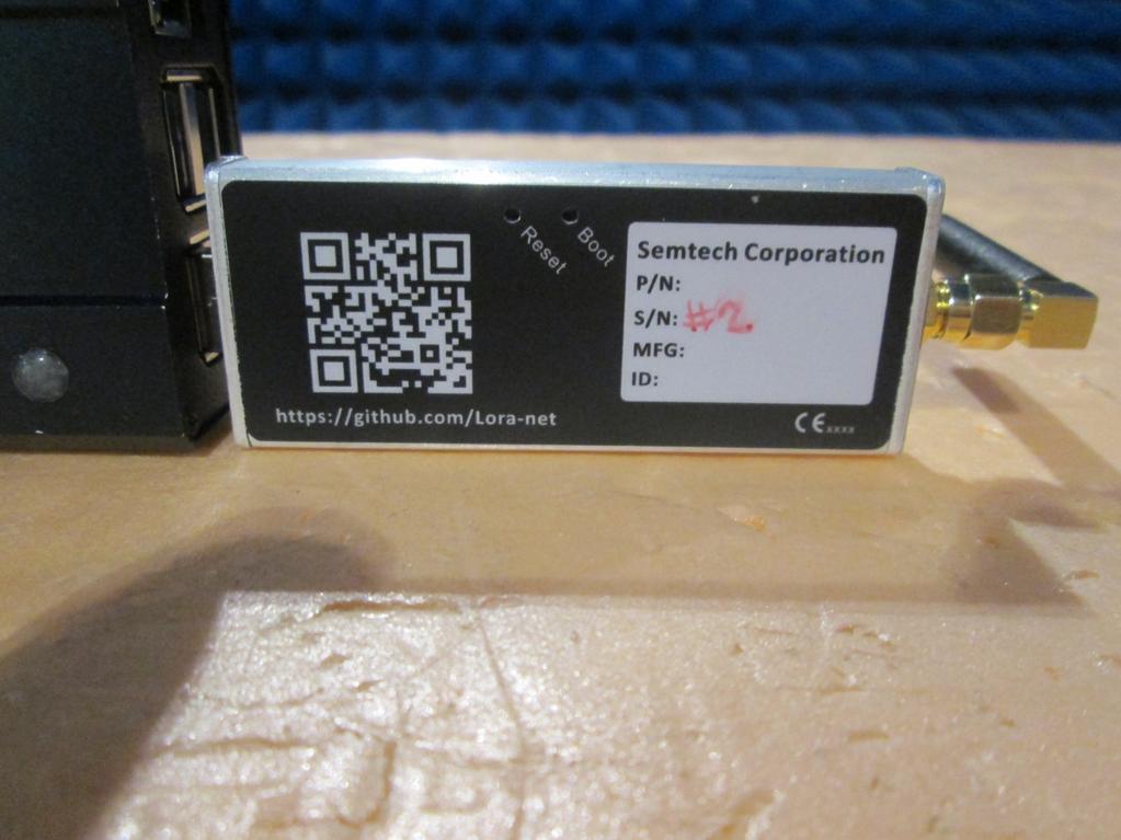
48 APPENDIX 1: Photographies of the equipment under test Page 48 out of 56

49 Page 49 out of 56

50 Page 50 out of 56
51 APPENDIX 2: Test set up Page 51 out of 56

52 Page 52 out of 56
53 APPENDIX 3: Test equipment list Page 53 out of 56
54 Average power (conducted) TYPE MANUFACTURER EMITECH N r DATE CAL. DATE VAL Spectrum Analyzer Rohde & &Schwarz /01/ /03/2017 Thermo-Hygrometer Testo /03/ /05/2017 Full-anechoic chamber Siepel /07/ /09/2018 Frequency error TYPE MANUFACTURER EMITECH N r DATE CAL. DATE VAL Spectrum Analyzer Rohde & &Schwarz /01/ /03/2017 Cable /07/ /09/2018 N-6m Cable Hytem /10/ /12/2018 N-7m Cable Hytem /04/ /06/2017 N-2.5m Cable Hytem /07/ /09/2018 Bilog Antenna Chase Electronics /09/ /11/2017 Frequencymeter Hewlett Packard 7809 N-16m Cable / /07/ /09/2018 Thermo-Hygrometer Testo /03/ /05/2017 Barometer Ranchet 5199 Power supply Sodilec 6481 Power supply Sodilec 6482 BAT Nexio 0000 Full-anechoic chamber Siepel /07/ /09/2018 Climatic Chamber Excal UHAP Antenna Schwarzbeck /01/ /03/2019 Effective radiated power TYPE MANUFACTURER EMITECH N r DATE CAL. DATE VAL Bilog Antenna Chase Electronics /09/ /11/2017 N-4m Cable Câbles & Connectiques /07/ /09/2018 Pre-amplifier RFPA /03/ /05/2017 N-10m Cable Hytem /07/ /09/2018 N-3m Cable /07/ /09/2018 Spectrum Analyzer Rohde & &Schwarz /01/ /03/2017 Full-anechoic chamber Siepel /07/ /09/2018 BAT Nexio 0000 Thermo-Hygrometer Testo /03/ /05/2017 Barometer Ranchet 5199 Transient power TYPE MANUFACTURER EMITECH N r DATE CAL. DATE VAL Spectrum Analyzer Agilent Technologies /03/ /05/2017 Thermo-Hygrometer Testo /03/ /05/2017 Barometer Ranchet 5199 Power Supply Sodilec 6482 BAT Nexio 0000 Page 54 out of 56
55 Modulation bandwidth TYPE MANUFACTURER EMITECH N r DATE CAL. DATE VAL Spectrum Analyzer Rohde & &Schwarz /01/ /03/2017 Cable /07/ /09/2018 N-6m Cable Hytem /10/ /12/2018 N-7m Cable Hytem /04/ /06/2017 Bilog Antenna Chase Electronics /09/ /11/2017 Thermo-Hygrometer Testo /03/ /05/2017 Barometer Ranchet 5199 Power Supply Sodilec 6482 BAT Nexio 0000 Full-anechoic chamber Siepel /07/ /09/2018 Multimeter Hewlett Packard /06/ /08/2018 Unwanted emissions in the spurious domain (conducted) TYPE MANUFACTURER EMITECH N r DATE CAL. DATE VAL Spectrum Analyzer Rohde & &Schwarz /01/ /03/2017 Thermo-Hygrometer Testo /03/ /05/2017 Full-anechoic chamber Siepel /07/ /09/2018 Unwanted emissions in the spurious domain (radiated) TYPE MANUFACTURER EMITECH N r DATE CAL. DATE VAL. Spectrum Analyzer Rohde & &Schwarz /01/ /03/2017 Pre amplifier RFPA /03/ /05/2017 N-3m Cable /07/ /09/2018 N-10m Cable Hytem /07/ /09/2018 N-4m Cable Câbles & Connectiques /07/ /09/2018 Bilog Antenna Chase Electronics /09/ /11/2017 Pre amplifier Agilent Technologies /10/ /12/2016 N-2.5m Cable Hytem /07/ /09/2018 N-6m Cable Hytem /10/ /12/2018 N-7m Cable Hytem /04/ /06/2017 N-5m Cable Hytem /01/ /03/2017 Horn antenna Schwarzbeck /12/ /02/2019 Thermo-Hygrometer Testo /03/ /05/2017 BAT Nexio 0000 Full-anechoic chamber Siepel /07/ /09/2018 Receiver spurious radiation (conducted) TYPE MANUFACTURER EMITECH N r DATE CAL. DATE VAL Spectrum Analyzer Rohde & &Schwarz /01/ /03/2017 Thermo-Hygrometer Testo /03/ /05/2017 Full-anechoic chamber Siepel /07/ /09/2018 Page 55 out of 56
56 Receiver spurious radiation (radiated) TYPE MANUFACTURER EMITECH N r DATE CAL. DATE VAL Spectrum Analyzer Rohde & &Schwarz /01/ /03/2017 Pre amplifier RFPA /03/ /05/2017 N-3m Cable /07/ /09/2018 N-10m Cable Hytem /07/ /09/2018 N-4m Cable Câbles & Connectiques /07/ /09/2018 Bilog Antenna Chase Electronics /09/ /11/2017 Pre amplifier Agilent Technologies /10/ /12/2016 N-2.5m Cable Hytem /07/ /09/2018 N-6m Cable Hytem /10/ /12/2018 N-7m Cable Hytem /04/ /06/2017 N-5m Cable Hytem /01/ /03/2017 Horn antenna Schwarzbeck /12/ /02/2019 Thermo-Hygrometer Testo /03/ /05/2017 Barometer Ranchet 5199 BAT Nexio 0000 Full-anechoic chamber Siepel /07/ /09/2018 Page 56 out of 56
RADIO TEST REPORT SHANGHAI EUCHIPS INDUSTRIAL CO.,LTD. Prepared By : SHANGHAI EUCHIPS INDUSTRIAL CO.,LTD
 SHANGHAI EUCHIPS INDUSTRIAL CO.,LTD RADIO TEST REPORT Prepared For : SHANGHAI EUCHIPS INDUSTRIAL CO.,LTD 3rd and 4th Floor,6th Building No.888,Shuangbai Road, Minhang District,Shanghai,China Product Name:
Radio Collocation test report
 RR51-14-16673-12-A Ed. Radio Collocation test report According to the standard: CFR47 FCC part 15 Equipment under test: RFID MODULE HF-ELYCTIS integrated in Biometric/RFID Handheld Control Terminal WA4e-ID-WG-OCR31e
REMARKS The customer has ordered two measurements mentioned above according to the standard EN
 Type: Alignment range: Switching range: SATELLINE-3ASm/250/LC 380,000-470,000 MHz One channel Equipment 1 and 2 Equipment Equipment Measurement Serial no. 033322036 and 033322037 Serial no. Serial no.
Electrical FOR:
 839.01 Electrical Hermon Laboratories Ltd. Harakevet Industrial Zone, Binyamina 30500, Israel Tel. +972-4-6288001 Fax. +972-4-6288277 E-mail: mail@hermonlabs.com TEST REPORT ACCORDING TO: EN 300 113-2
FCC Test Report. Report No.: AGC FE02 CLIENT : INNOVATIVE CONCEPTS AND DESIGN LLC. Attestation of Global Compliance (Shenzhen) Co., Ltd.
 Co., Ltd.") Page 1 of 43 FCC Test Report Report No.: AGC03588150607FE02 FCC ID : 2AE6GUHF 6000HHM APPLICATION PURPOSE : ORIGINAL EQUIPMENT PRODUCT DESIGNATION : Wireless Microphone BRAND NAME : Gemini MODEL NAME :
Page 1 of 43 FCC Test Report Report No.: AGC03588150607FE02 FCC ID : 2AE6GUHF 6000HHM APPLICATION PURPOSE : ORIGINAL EQUIPMENT PRODUCT DESIGNATION : Wireless Microphone BRAND NAME : Gemini MODEL NAME :
Title: Test on 5.8 GHz Band Outdoor WiFi (802.11b/g) Wireless Base Station
 Wireless Base Station") Page 20 of 51 Pages 7.5. Conducted spurious emission 7.5.1. Requirements: Clause 15.247(d). In any 100 khz bandwidth outside the frequency band in which the spread spectrum or digitally modulated intentional
Page 20 of 51 Pages 7.5. Conducted spurious emission 7.5.1. Requirements: Clause 15.247(d). In any 100 khz bandwidth outside the frequency band in which the spread spectrum or digitally modulated intentional
EUROFINS PRODUCT SERVICE GMBH EN V Tracking solution. Bolero-LT2
 EUROFINS PRODUCT SERVICE GMBH RADIO TEST-REPORT EN 300 440 V1.4.1 Tracking solution Bolero-LT2 TEST REPORT NUMBER: G0M-1103-1037-T-42 Eurofins Product Service GmbH Storkower Str. 38c, 15526 Reichenwalde,
DATES OF TESTS: From 03/10/2014 to 20/10/2014 and 25/02/2015. Open area test site in Aunainville (28) - FRANCE. Page 2 out of 54
 - FRANCE. Page 2 out of 54") TEST CERTIFICATION FOR: FCC Certification NAME OF THE EQUIPMENT UNDER TEST: Serial number: Wireless conference access point Type: CONFIDEA WCAP G3 1440077150000C1 Reference / model (P/N): 71.98.0033 V
TEST CERTIFICATION FOR: FCC Certification NAME OF THE EQUIPMENT UNDER TEST: Serial number: Wireless conference access point Type: CONFIDEA WCAP G3 1440077150000C1 Reference / model (P/N): 71.98.0033 V
EUROFINS PRODUCT SERVICE GMBH EN V1.6.1 EN V Asset tracker. Rock
 EUROFINS PRODUCT SERVICE GMBH RADIO TEST- REPORT EN 300 440-1 V1.6.1 EN 300 440-2 V1.4.1 Asset tracker Rock TEST REPORT NUMBER: G0M-1103-1036-T-42 Eurofins Product Service GmbH Storkower Str. 38c, 15526
ETSI EN RADIO TEST REPORT
 Report No:DDT-RE140701 Issued Date: Oct.23,2014 ETSI EN300 220 RADIO TEST REPORT FOR Applicant : HOPE MICROELECTRONICS CO.,LTD 2/F,Building3,pingshan Private Enterprise science and Address : Technology
RADIO TEST REPORT ETSI EN V2.4.1( ) For
 For") RADIO TEST REPORT ETSI EN 300 220-2 V2.4.1(2012-05) For Applicant : CNEX AIE SL Address : C/ Mendez Nuñez,49 08302 Mataró - Barcelona - Spain Product Name : Massager 33431, 107530, 108216, 108339, 108735,
RADIO TEST REPORT ETSI EN 300 220-2 V2.4.1(2012-05) For Applicant : CNEX AIE SL Address : C/ Mendez Nuñez,49 08302 Mataró - Barcelona - Spain Product Name : Massager 33431, 107530, 108216, 108339, 108735,
Certification Radio test report
 RR051-16-102195-5-A Ed. 1 This report cancels and replaces the test report N RR051-16-102195-5-A Ed. 0 Certification Radio test report According to the standard: CFR 47 FCC PART 15 Equipment under test:
EXHIBIT 7: MEASUREMENT PROCEDURES Pursuant 47 CFR 2.947
 EXHIBIT 7: MEASUREMENT PROCEDURES Pursuant 47 CFR 2.947 7.1 RF Power -- Pursuant to 47 CFR 2.947(c) Method of Conducted Output Power Measurement: Adaptation of TIA/EIA-603-A clause 2.2.1 for Pulsed Measurements
XBee Series 2 OEM RF Module Model No.: XBEE2 FCC ID: OUR-XBEE2. Applicant: MaxStream, Inc. 355 South 520 West Suite 180 Lindon, UT 84042
 XBee Series 2 OEM RF Module Model No.: XBEE2 Applicant: MaxStream, Inc. 355 South 520 West Suite 180 Lindon, UT 84042 In Accordance With Federal Communications Commission (FCC) Part 15, Subpart C, Section
FCC PART 95 MEASUREMENT AND TEST REPORT. Powerwerx, Inc.
 FCC PART 95 MEASUREMENT AND TEST REPORT For Powerwerx, Inc. 23695 Via Del Rio Yorba Linda California 92887, United States FCC ID: 2ACK8TR505D Report Type: Original Report Product Type: Two-way radio Test
Ave output power ANT 1(dBm) Ave output power ANT 2 (dbm)
 Ave output power ANT 2 (dbm)") Page 41 of 103 9.6. Test Result The test was performed with 802.11b Channel Frequency (MHz) power ANT 1(dBm) power ANT 2 (dbm) power ANT 1(mW) power ANT 2 (mw) Limits dbm / W Low 2412 7.20 7.37 5.248 5.458
Page 41 of 103 9.6. Test Result The test was performed with 802.11b Channel Frequency (MHz) power ANT 1(dBm) power ANT 2 (dbm) power ANT 1(mW) power ANT 2 (mw) Limits dbm / W Low 2412 7.20 7.37 5.248 5.458
EMC Test Data. Radio Test Report R Summit Data Communications SDC-MCF10G. Test Report R76253 Rev 3.0. Revision History.
 EMC Test Data Radio Test Report R76253 For The Summit Data Communications Model SDC-MCF10G Revision History Rev # Made By Date Comments 1.0 Mark Hill 31-Jul-09 Initial Release 2.0 Mark Briggs 11-Aug-09
SAR TEST REPORT. According to the standard: EN : Equipment under test: Horizontal case for Smartphone Duthilleul Process
 SAR TEST REPORT According to the standard: EN 62209-1: 2006 Equipment under test: Horizontal case for Smartphone Duthilleul Process Tested with a SAMSUNG Galaxy S4 (GT-I9505) Company: Mr. DUTHILLEUL DISTRIBUTION:
FCC & IC Certification. Test Report. FCC & Industry Canada Certification. Test Report. for Hetronic USA FCC ID: LW9-CS434TXN IC ID: 2219A-CS434TXN
 FCC & IC Certification Test Report FCC & Industry Canada Certification Test Report for Hetronic USA March 3, 2005 Prepared for: Hetronic USA 4300 Highline Blvd Building 4 Oklahoma City, OK 73108 Prepared
EN / EN RADIO TEST REPORT. Shanghai Anviz Technology Co.Ltd Fingerprint & RFID Time Attendance Model No.: A300
 Page 1 of 28 Report No.: T1861387 02 EN 300 330-1/ EN 300 330-2 RADIO TEST REPORT On Behalf of Shanghai Anviz Technology Co.Ltd Fingerprint & RFID Time Attendance Model No.: A300 Prepared for : Shanghai
EN RADIO Test REPORT
 Page 1 of 53 EN 300 086 RADIO Test REPORT On Behalf of Zhengzhou Eshow Import and Export Trade Co., Ltd. Two way radio Model No.: RT-5RV Prepared for : Zhengzhou Eshow Import and Export Trade Co., Ltd.
TEST REPORT NO. DATE DESCRIPTION
 Version TEST REPORT NO. DATE DESCRIPTION HCT-R-1608-F020 August 19, 2016 - First Approval Report 2 / 50 Table of Contents 1. GENERAL INFORMATION... 4 2. INTRODUCTION... 5 2.1. EUT DESCRIPTION... 5 2.2.
Version TEST REPORT NO. DATE DESCRIPTION. HCTR1208FR50 August 29, 2012 First Approval Report
 Version TEST REPORT NO. DATE DESCRIPTION First Approval Report Page 2 of 101 Table of Contents 1. GENERAL INFORMATION... 4 2. INTRODUCTION... 5 2.1. EUT DESCRIPTION... 5 2.2. MEASURING INSTRUMENT CALIBRATION...
R&TTE (1999/5/EC) Directive ETSI EN V1.8.1: 2012 TEST REPORT
 Directive ETSI EN V1.8.1: 2012 TEST REPORT") Page: 1 of 50 R&TTE (1999/5/EC) Directive ETSI EN 300 328 V1.8.1: 2012 TEST REPORT FOR Product Name: Brand Name: Model No.: Model Different: Report No.: TomTom GPS watch TomTom 8RS00 N/A EF/2013/20012-01
Page: 1 of 50 R&TTE (1999/5/EC) Directive ETSI EN 300 328 V1.8.1: 2012 TEST REPORT FOR Product Name: Brand Name: Model No.: Model Different: Report No.: TomTom GPS watch TomTom 8RS00 N/A EF/2013/20012-01
RF test report AU01+W02
 Customer: Kehlbergstrasse 109 8054 Graz Austria Tel.: +43 664 415 6260 RF test report 170186-AU01+W02 The test result refers exclusively to the tested model. This test report may not be copied or published
Revision history. Revision Date of issue Test report No. Description KES-RF-14T0042 Initial
 Page (2 ) of (34) Revision history Revision Date of issue Test report No. Description - 2014.08.25 Initial Page (3 ) of (34) TABLE OF CONTENTS 1. General information... 4 1.1. EUT description... 4 1.2.
EMC Test Report. Tested by: Jeremy O. Pickens, Senior EMC Engineer. Reviewed by: David Schramm, EMC/RF/SAR/HAC Manager
 Page: 1 of 24 EMC Test Report Project Number: 4104971 Report Number: 4104971EMC01 Revision Level: 0 Client: Tier One, Inc. Equipment Under Test: GEN4 Glock Sensor Model Number: BA10232 FCC ID: 2AJ3810232
RF Test Report. Report No.: AGC EE13. CLIENT : Zhengzhou Eshow Import and Export Trade Co.,Ltd.
 Page 1 of 80 RF Test Report Report No.: AGC08074160901EE13 PRODUCT DESIGNATION : Two way radio BRAND NAME : Retevis MODEL NAME : RT1 CLIENT : Zhengzhou Eshow Import and Export Trade Co.,Ltd. DATE OF ISSUE
OUTDOOR SOUND MODULE/TRANSMITTER MODEL: THE BANDIT
 Page 1 of 16 FCC PART 15, SUBPART B and C TEST REPORT for OUTDOOR SOUND MODULE/TRANSMITTER MODEL: THE BANDIT Prepared for MINASKA OUTDOORS 6517 PLATTE AVENUE LINCOLN, NEBRASKA 68507 Prepared by: KYLE FUJIMOTO
For. Unit D16/F. should not use it to claim FCC ID: 2AAIN-MNGLOS
 Page 1 of 49 TESTT REPORT For Applicant : ACOUSTMAX INTERNATIONAL CO.., LTD Unit D16/F Cheuk Nang Plaza 250 Hennessy Road Address : WanchaiHongKong Product Name : Monster GLO Model Name : MNGLO-S, MNGLO-L,MNGLO-M,MNGLO-Mini
EXHIBIT 10 TEST REPORT. FCC Parts 2 & 24
 EXHIBIT 10 TEST REPORT FCC Parts 2 & 24 SUB-EXHIBIT 10.1 MEASUREMENT PER SECTION 2.1033 (C) (14) OF THE RULES SECTION 2.1033 (c) (14) The data required by Section 2.1046 through 2.1057, inclusive, measured
Date: ESPOO Page: 1 ( 10) Appendices - Transceiver. SATELLINE-EASy Pro 35W SATEL-TA18 SATEL Oy, Finland
 Appendices - Transceiver. SATELLINE-EASy Pro 35W SATEL-TA18 SATEL Oy, Finland") Version R3.03 09092003 TEST REPORT Date: ESPOO 05.10.2010 Page: 1 ( 10) Appendices - Number: 157439 No. 1 / 1 Date of handing in: 17.09.2010 Tested by: Timo Hietala, Test Engineer Reviewed by: Timo Leismala,
Version R3.03 09092003 TEST REPORT Date: ESPOO 05.10.2010 Page: 1 ( 10) Appendices - Number: 157439 No. 1 / 1 Date of handing in: 17.09.2010 Tested by: Timo Hietala, Test Engineer Reviewed by: Timo Leismala,
FCC Test Report. : Wireless Way Richmond, BC, V6V 3A4 Canada : 47 CFR FCC Part 27 Subpart L
 FCC Test Report FCC ID Equipment Model No. Brand Name Applicant Address Standard : N7NHL7688 : Wireless Module : HL7688 : AirPrime : Sierra Wireless Inc. Received Date : Jul. 12, 2016 : 13811 Wireless
FCC 47 CFR PART 15 SUBPART C INDUSTRY CANADA RSS-210 ISSUE 8 BLUETOOTH LOW ENERGY CERTIFICATION TEST REPORT FOR. 2.4GHz LE MODULE MODEL NUMBER: RN4020
 FCC 47 CFR PART 15 SUBPART C INDUSTRY CANADA RSS-210 ISSUE 8 BLUETOOTH LOW ENERGY CERTIFICATION TEST REPORT FOR 2.4GHz LE MODULE MODEL NUMBER: RN4020 REPORT NUMBER: 14U17191-1 ISSUE DATE: MARCH 21, 2014
ETSI EN V1.1.1 ( )
") EN 300 220-4 V1.1.1 (2017-02) HARMONISED EUROPEAN STANDARD Short Range Devices (SRD) operating in the frequency range 25 MHz to 1 000 MHz; Part 4: Harmonised Standard covering the essential requirements
EN 300 220-4 V1.1.1 (2017-02) HARMONISED EUROPEAN STANDARD Short Range Devices (SRD) operating in the frequency range 25 MHz to 1 000 MHz; Part 4: Harmonised Standard covering the essential requirements
RADIOCOMMUNICATIONS TESTING
 2/F., Garment Centre, 576 Castle Peak Road, Kowloon, Hong Kong. Telephone: (852) 2173 8888 Facsimile: (852) 2785 5487 www.intertek.com RADIOCOMMUNICATIONS TESTING NPD LTD. 73020R WALKIE TALKIES : TEST
ENGINEERING TEST REPORT # C LSR Job #: C-2411 Compliance Testing of: RM186-SM
 W66 N220 Commerce Court Cedarburg, WI 53012 USA Phone: 262.375.4400 Fax: 262.375.4248 www.lsr.com ENGINEERING TEST REPORT # 316062C LSR Job #: C-2411 Compliance Testing of: RM186-SM Test Date(s): 3-28-16
A Test Lab Techno Corp. Report Number:1410FR27
 Mode 5: IEEE 802.11n 2.4GHz 40MHz Link Mode 2422 2437 2452 Page 41 of 85 9 Out of Band Conducted Emissions Measurement 9.1. Limit In any 100 khz bandwidth outside the frequency band in which the spread
Version TEST REPORT NO. DATE DESCRIPTION. HCTR1208FR49 August 29, 2012 First Approval Report
 Version TEST REPORT NO. DATE DESCRIPTION HCTR1208FR49 August 29, 2012 First Approval Report Revise information for frequency range on page 8 Page 2 of 39 Table of Contents 1. GENERAL INFORMATION... 4 2.
TEST REPORT N B Page 2
 TEST REPORT N 120636-641067B Page 2 TABLE OF CONTENTS 1 GENERAL 1.1 Summary of test results Page 3 1.2 References Page 3 1.3 Equipment under test specification Page 4 2 TEST RESULTS 2.1 Power line conducted
TCN : RADIO EQUIPMENTS OPERATING IN THE 2.4 ghz BAND and USING SPREAD SPECTRUM MODULATION TECHNIQUES. Technical Requirements
 TCN 68-242: 2006 RADIO EQUIPMENTS OPERATING IN THE 2.4 ghz BAND and USING SPREAD SPECTRUM MODULATION TECHNIQUES Technical Requirements 29 CONTENTS FOREWORD... 31 1. Scope...32 2. Normative References...32
FCC Part 22H & 24E Measurement and Test Report
 FCC Part 22H & 24E Measurement and Test Report For Shenzhen Concox Information Technology Co., Ltd Floor 4th, Building B, Gaoxinqi Industrial Park, Liuxian 1st Road, District 67, Bao an, Shenzhen, China
SPECTRUM REPORT Dragino Technology Co., Limited
 Report No.: GTS201705000186E03 Applicant: SPECTRUM REPORT Dragino Technology Co., Limited Address of Applicant: Manufacturer/ Factory: Room 1101, City Invest Commercial Center, No.546 QingLinRoad, LongCheng
Chapter I - Federal Communications Commission Subchapter A - General Part 15 - Radio Frequency Devices Subpart C - Intentional Radiators
 www.nemko.com Report Reference ID 167484-1TRFWL Test specification Title 47 - Telecommunication Chapter I - Federal Communications Commission Subchapter A - General Part 15 - Radio Frequency Devices Subpart
G.S.D. S.r.l. Via Marmiceto, Pisa (loc. Ospedaletto) Italy MARKING. Test Report n. FCC CAEN RFID S.r.l Viareggio (LU) Italy
 Italy MARKING. Test Report n. FCC CAEN RFID S.r.l Viareggio (LU) Italy") MARKING Laboratories ELECTROMAGNETIC COMPATIBILITY ELECTRICAL SAFETY LASER SPECTROSCOPY ENVIRONMENTAL PHYSICS G.S.D. Srl PISA - Italy Test Report n. FCC-17337 Manufacturer Address CAEN RFID S.r.l. Test
MARKING Laboratories ELECTROMAGNETIC COMPATIBILITY ELECTRICAL SAFETY LASER SPECTROSCOPY ENVIRONMENTAL PHYSICS G.S.D. Srl PISA - Italy Test Report n. FCC-17337 Manufacturer Address CAEN RFID S.r.l. Test
Measurement Procedure & Test Equipment Used
 Measurement Procedure & Test Equipment Used Except where otherwise stated, all measurements are made following the Electronic Industries Association (EIA) Minimum Standard for Portable/Personal Land Mobile
TEST REPORT Part 95(A/B) & IC RSS-210(Issue 8)
 & IC RSS-210(Issue 8)") TEST REPORT Part 95(A/B) & IC RSS-210(Issue 8) Equipment Under Test FRS / GMRS Model Name LXT600 FCC ID MMALXT600 IC Certification 3690A- LXT600 Applicant Midland Radio Corporation Manufacturer Global
TEST REPORT Part 95(A/B) & IC RSS-210(Issue 8) Equipment Under Test FRS / GMRS Model Name LXT600 FCC ID MMALXT600 IC Certification 3690A- LXT600 Applicant Midland Radio Corporation Manufacturer Global
N : B Version : 01. Written by : Approved by :
 Bluetooth Classic Template: Release October 03rd, 2016 N : 146019-698067B Version : 01 Subject Radio spectrum matters tests according to standards: 47 CFR Part 15.247 Issued to SAGEMCOM BROADBAND SAS 250
R. Grant, Wireless Group Manager
 KTL Test Report: 9R02216 Applicant: Daniels Electronics Ltd. 43 Erie Street Victoria, BC V8V 1P8 Equipment Under Test: (E.U.T.) Transmitter (VT-3A130) In Accordance With: FCC Part 87, Subpart D Tested
FCC ID: A3LSLS-BD106Q. Report No.: HCT-RF-1801-FC003. Plot Data for Output Port 2_QPSK 9 khz ~ 150 khz Middle channel 150 khz ~ 30 MHz Low channel
 Plot Data for Output Port 2_QPSK 9 khz ~ 150 khz Middle channel 150 khz ~ 30 MHz Low channel 30 MHz ~ 1 GHz Middle channel 1 GHz ~ 2.491 GHz Low channel 2.695 GHz ~ 12.75 GHz High channel 12.75 GHz ~ 26.5
ETSI EN V1.3.1 ( )
") EN 300 328-1 V1.3.1 (2001-12) European Standard (Telecommunications series) Electromagnetic compatibility and Radio spectrum Matters (ERM); Wideband Transmission systems; Data transmission equipment operating
EN 300 328-1 V1.3.1 (2001-12) European Standard (Telecommunications series) Electromagnetic compatibility and Radio spectrum Matters (ERM); Wideband Transmission systems; Data transmission equipment operating
TEST REPORT FROM RFI GLOBAL SERVICES LTD
 FROM RFI GLOBAL SERVICES LTD Test of: C-Track NX55 To: EN 300 440-1 V1.6.1 (2010-08) in accordance with EN 300 440-2 V1.4.1 (2010-08) Test Report Serial No.: RFI-RPT-RP84347JD02A This Test Report Is Issued
FCC Test Report. Wayne Hsu / Assistant Manager
 FCC Test Report Equipment : Wireless Pedometer/Tracker Brand Name : ASE Group Model No. : M903 Standard : 47 CFR FCC Part 15.247 Operating Band : 2400 MHz 2483.5 MHz FCC Classification : DTS Applicant
Test Report. Report Number: F161141E1. Equipment under Test (EUT): AIS Class B SO Transponder WideLink B600. Applicant:
: AIS Class B SO Transponder WideLink B600. Applicant:") Königswinkel 10 32825 Blomberg, Germany Phone: +49 (0) 52 35 / 95 00-0 Fax: +49 (0) 52 35 / 95 00-10 office@phoenix-testlab.de www.phoenix-testlab.de Test Report Report Number: F161141E1 Equipment under
Königswinkel 10 32825 Blomberg, Germany Phone: +49 (0) 52 35 / 95 00-0 Fax: +49 (0) 52 35 / 95 00-10 office@phoenix-testlab.de www.phoenix-testlab.de Test Report Report Number: F161141E1 Equipment under
ETSI EN V2.1.1 ( )
") EN 300 440 V2.1.1 (2017-03) HARMONISED EUROPEAN STANDARD Short Range Devices (SRD); Radio equipment to be used in the 1 GHz to 40 GHz frequency range; Harmonised Standard covering the essential requirements
EN 300 440 V2.1.1 (2017-03) HARMONISED EUROPEAN STANDARD Short Range Devices (SRD); Radio equipment to be used in the 1 GHz to 40 GHz frequency range; Harmonised Standard covering the essential requirements
TEST REPORT. For RFID READER/WRITER. In conformity with. FCC CFR 47 Part15 Subpart C
 TEST REPORT For RFID READER/WRITER In conformity with FCC CFR 47 Part15 Subpart C Model: TR3XM-SD01 / TR3XM-SU01 / TR3XM-SN01 FCC ID: MK4TR3XM-SX01 Test Item: RFID READER/WRITER Report No: RY1203Z12R1
Compliance Engineering Ireland Ltd
 Page 1 of 27 Compliance Engineering Ireland Ltd RAYSTOWN, RATOATH ROAD, ASHBOURNE, CO. MEATH, IRELAND Tel: +353 1 8256722 Fax: +353 1 8256733 Project Number: 10E2475-5 Prepared for: Biancamed Ltd By Compliance
FCC Part 90 Rules Test Report
 Page 1 of 147 FCC Part 90 Rules Test Report FCC ID : POD-DMR2 PRODUCT DESIGNATION : DMR Digital Transceiver BRAND NAME : TYT MODEL NAME : MD-2017, MD-760 CLIENT : TYT ELECTRONICS CO., LTD DATE OF ISSUE
Page 1 of 51 Report No.: T TEST REPORT FCC ID: 2AGJ5WAP-30. In Accordance with: FCC PART 15, SUBPART C : 2015 (Section 15.
 Page 1 of 51 Report No.: T1851663 01 TEST REPORT FCC ID: 2AGJ5WAP-30 Applicant Address : Gonsin Conference Equipment Co., Ltd : No.401-406,Block C, Idea Industry Park, No.41 Fengxiang Road, Shunde, Foshan,
RF Test Report. Report No.: AGC EE10. TEST NAME : 1999/5/EC R&TTE Directive Art.3.2 STANDARD(S) : EN V : V1.
 : EN V : V1.") Page 1 of 49 RF Test Report Report No.: AGC05278160201EE10 TEST NAME : 1999/5/EC R&TTE Directive Art.3.2 PRODUCT DESIGNATION : ihere3.0 BRAND NAME : ihere3.0 MODEL NAME : ihere3.0 CLIENT : No NDA Inc.
Page 1 of 49 RF Test Report Report No.: AGC05278160201EE10 TEST NAME : 1999/5/EC R&TTE Directive Art.3.2 PRODUCT DESIGNATION : ihere3.0 BRAND NAME : ihere3.0 MODEL NAME : ihere3.0 CLIENT : No NDA Inc.
TRANSMITTER MODEL: KAS-2030M
 Page 1 of 16 FCC PART 15, SUBPART B and C TEST REPORT for TRANSMITTER MODEL: KAS-2030M Prepared for WILDLIFE TECHNOLOGIES 115 WOLCOTT STREET MANCHESTER, NEW HAMPSHIRE 03103 Prepared by: KYLE FUJIMOTO Approved
Applicant : FIC (First International Computer, Inc.)
") ERB Equipment : Neo 1973 Trade Name : FIC Model Name : GTA01BV4 Applicant : FIC (First International Computer, Inc.) No. 300, Yang Guang, NeiHu, Taipei, Taiwan, 114 THE MEASUREMENTS SHOWN IN THIS TEST
ERB Equipment : Neo 1973 Trade Name : FIC Model Name : GTA01BV4 Applicant : FIC (First International Computer, Inc.) No. 300, Yang Guang, NeiHu, Taipei, Taiwan, 114 THE MEASUREMENTS SHOWN IN THIS TEST
Vertex Standard Co., Ltd. Page 1 of 38
 Page 1 of 38 REPORT ON Radio testing of the VERTEX STANDARD VX-2100-G6-45 / VX-2200-G6-45 In accordance with ANSI/TIA/EIA-603-C, RSS-119 Report number TA001110 December 2011 Report number TA001110 Page
STC Test Report. Date : Page 1 of 13 No. : HM161169
 Date : 2009-05-11 Page 1 of 13 Applicant (ATS001): Atech Scientific Measurement Limited. Room A-C, 18 Floor, Luk Hop Ind. Bldg, 8 Luk Hop Street, Kowloon Manufacturer: Atech Scientific Measurement Limited.
TEST REPORT. Test Report No. : UL-RPT-RP JD02A V3.0. Date of Issue: 06 October 2017
 Test Report No. : UL-RPT-RP11327903JD02A V3.0 Manufacturer : Kontakt Micro-Location Sp. z o.o. Model No. : Kontakt Smart Beacon 2 FCC ID : 2ADAO-SB2-V250 Technology : Bluetooth Low Energy Test Standard(s)
AS/NZS TEST REPORT. : Wireless IR Repeater System
 AS/NZS TEST REPORT Equipment : Wireless IR Repeater System Model No. : A-1369 I HEREBY CERTIFY THAT : The sample was received on Dec. 01, 2016 and the testing was carried out on Dec. 01, 2016 at Cerpass
FCC Part 90 Rules Test Report
 Page 1 of 147 FCC Part 90 Rules Test Report FCC ID : POD-DMR2 PRODUCT DESIGNATION : DMR Digital Transceiver BRAND NAME : TYT MODEL NAME : MD-2017, MD-760 CLIENT : TYT ELECTRONICS CO., LTD DATE OF ISSUE
ACCORDING TO: FCC part 15 subpart C, and subpart B FOR:
 Electrical Hermon Laboratories Ltd. P.O.Box 23, Binyamina 30500, Israel Tel. +972 4628 8001 Fax. +972 4628 8277 E-mail: mail@hermonlabs.com TEST REPORT ACCORDING TO: FCC part 15 subpart C, 15.247 and subpart
Table of Contents 1. GENERAL INFORMATION SYSTEM TEST CONFIGURATION CONDUCTED EMISSIONS TEST RADIATED EMISSION TEST...
 Table of Contents 1. GENERAL INFORMATION... 4 1.1 PRODUCT DESCRIPTION FOR EQUIPMENT UNDER TEST... 4 1.2 RELATED SUBMITTAL(S) / GRANT (S)... 7 1.3 TEST METHODOLOGY... 7 1.4 EQUIPMENT MODIFICATIONS... 7
REPORT ON Radio testing of the VERTEX STANDARD VX-2100-G6-45 / VX-2200-G6-45 In accordance with ANSI/TIA/EIA-603, RSS-119. Report number TA000506
 Page 1 of 48 REPORT ON Radio testing of the VERTEX STANDARD VX-2100-G6-45 / VX-2200-G6-45 In accordance with ANSI/TIA/EIA-603, RSS-119 Report number TA000506 June 2007 Report number TA000506 Page 2 of
FCC CFR47 PART 15 SUBPART C INDUSTRY CANADA RSS-GEN AND RSS-210 CERTIFICATION TEST REPORT FOR BROADCOM BLUETOOTH MODULE MODEL NUMBER: BCM92046MD
 FCC CFR47 PART 15 SUBPART C INDUSTRY CANADA RSS-GEN AND RSS-210 CERTIFICATION TEST REPORT FOR BROADCOM BLUETOOTH MODULE MODEL NUMBER: BCM92046MD IC #: 4324A-BRCM1029 REPORT NUMBER: 07U11199-1C ISSUE DATE:
Spectrian Dual Mode Cellular Power Amplifier Model No.: SCLPA 800 CR FCC ID: I2ONTHX51AA
 A Class II Permissive Change - FCC Part 22 Type Acceptance Test Report for Spectrian Dual Mode Cellular Power Amplifier Model No.: SCLPA 800 CR FCC ID: I2ONTHX51AA Date of Report: May 26, 1999 Total No.
FCC Part 90 Certification Application. FCC Form 731. For The. Guardian UHF RADIO MODEM FCC ID: NP
 Page 1 of 41 CAlamp Wireless Networks Corp. 299 Johnson Avenue, Suite 110 Waseca, MN 56093-0833 USA Phone: 507-833-8819 Fax: 507-833-6748 FCC Part 90 Certification Application FCC Form 731 For The Guardian
N : A Version : 01. Test date : December 5, 2016 to December 21, 2016 Fontenay Aux Roses & Ecuelles Composition of document 47 pages
 Bluetooth Low Energy Template: Release August 20th, 2016 N : 146019-698067A Version : 01 Subject Radio spectrum matters tests according to standards: 47 CFR Part 15.247 Issued to SAGEMCOM BROADBAND SAS
SHURE ELECTROMAGNETIC COMPATIBILITY LABORATORY TEST REPORT
 SHURE ELECTROMAGNETIC COMPATIBILITY LABORATORY TEST REPORT TEST REPORT TITLE: Electromagnetic Compatibility Tests of the Shure QLXD2-V50 Handheld Transmitter TEST ITEM DESCRIPTION: QLXD2-V50 is a digital
FCC PART & IC RSS GHz FHSS TEST REPORT
 FCC PART 15.247 & IC RSS-247 2.4 GHz FHSS TEST REPORT 849 NW State Road 45 Newberry, FL 32669 USA Ph.: 888.472.2424 or 352.472.5500 Fax: 352.472.2030 Email: info@timcoengr.com Website: www.timcoengr.com
For Sky. Phone LLC. FCC Part 22H. FCC Rules: 3G Smart Phone. Report No.: By: Tested By: Manager. Prepared. Shenzhen SEM.
 FCC Part 22H & 24E Measurement and Test Report For Sky Phone LLC 1348 Washington Av. Suite 350, Miamii Beach, Florida, F United States FCCC ID: 2ABOSSKYPLATA55 FCC Rules: Product Description: Tested Model:
Version TEST REPORT NO. DATE DESCRIPTION
 Version NO. DATE DESCRIPTION HCTR1302FR13 February 14, 2013 - First Approval Report - Additional Model Name Page 2 of 25 Table of Contents 1. GENERAL INFORMATION... 4 2. EUT DESCRIPTION... 4 3. TEST METHODOLOGY...
TRFWL. Autostart Inc Rue Paré Mont-Royal, Québec Canada, H4P 2M2 EZSNAH2503
 Nemko Test Report: 109054-1TRFWL Applicant: Autostart Inc. 5764 Rue Paré Mont-Royal, Québec Canada, H4P 2M2 Apparatus: ASRA 2503 FCC ID: EZSNAH2503 In Accordance With: FCC Part 15 Subpart B, 15.107 and
FCC PART 95 MEASUREMENT AND TEST REPORT HENAN ESHOW ELECTRONIC COMMERCE CO., LTD
 FCC PART 95 MEASUREMENT AND TEST REPORT For HENAN ESHOW ELECTRONIC COMMERCE CO., LTD Room 722, Sanjiang Building, No.170 Nanyang Road, Huiji District, Zhengzhou, Henan, China FCC ID: 2AAR8RETEVISRT27 Report
As the responsible EMC Engineer, I hereby declare that the equipment tested as specified in this report conforms to the requirements indicated.
 MOBILE DEVICES BUSINESS PRODUCT SAFETY AND COMPLIANCE EMC LABORATORY EMC TEST REPORT Test Report Number 24262-1 WLAN Report Date December 17, 2010 The test results contained herein relate only to the model(s)
ADDENDUM TEST REPORT
 Page : 1 of 19 ADDENDUM TEST REPORT Test Report No. : 11707924M Applicant : TAIYO YUDEN CO., LTD. Type of Equipment : Bluetooth Smart / ANT Module Model No. : EYSHCN Test standard : EN 300 328 V2.1.1 (Except
CE Test Report. : Bluetooth 4.2 module (BLE only) (Refer to item for more details)
 (Refer to item for more details)") CE Test Report Equipment Model No. Brand Name Applicant Address : Bluetooth 4.2 module (BLE only) : BL652-SA, BL652-SC (Refer to item 1.1.1 for more details) : Laird Technologies : Laird Technologies :
CE Test Report Equipment Model No. Brand Name Applicant Address : Bluetooth 4.2 module (BLE only) : BL652-SA, BL652-SC (Refer to item 1.1.1 for more details) : Laird Technologies : Laird Technologies :
Measurement and Test Report
 Measurement and Test Report According to MIC Public Notice 88:2004 Annex 43 For Shenzhen Soundsoul Information Technology Co., Ltd Room 601 Building A4, ZhongYuGuan lnd Zone, Zhongyuguan road, longhua
FCC C2PC Test Report
 FCC C2PC Test Report FCC ID Equipment Model No. Brand Name Applicant : SQGBT800 : BTv4.0 Dual Mode USB Dongle : BT820 : Laird Technologies : Laird Technologies Address : 11160 Thompson Ave. / Lenexa, Kansas
Measurement of RF Interference from a Canopy 900MHz Access Point and Subscriber Module Using A Yagi Antenna
 Measurement of RF Interference from a Canopy 900MHz Access Point and Subscriber Module Using A Yagi Antenna For : Motorola, Inc. 1301 East Algonquin Road Schaumburg, IL 60196 P.O. No. : 40335 Date Tested
TEST SUMMARY Seite 2 von 31. Prüfbericht - Nr.: Test Report No ANTENNA REQUIREMENT RESULT: Pass
 Prüfbericht - Nr.: Test Report No. Seite 2 von 31 Page 2 of 31 TEST SUMMARY 5.1.1 ANTENNA REQUIREMENT RESULT: Pass 5.1.2 PEAK OUTPUT POWER RESULT: Pass 5.1.3 26DB BANDWIDTH RESULT: Pass 5.1.4 FREQUENCY
FCC Test Report. : ASE Group 4F,No 133, Sec 4, Mingsheng E Rd, Songshan Dist, Taipei, Taiwan
 FCC Test Report Equipment : Wireless Pedometer/Tracker Brand Name : ASE Group Model No. : M903 Standard : 47 CFR FCC Part 15B Device Class : Class B Applicant Manufacturer : ASE Group 4F,No 133, Sec 4,
FCC PART 15C & RSS 247 TEST REPORT
 FCC PART 15C & RSS 247 TEST REPORT No. I18N01184-WLAN for Spectralink Corp GSM Quad-band/UMTS five-band/lte/ca Mobile phone 9640 with Hardware Version: PIO Software Version: vf03 FCC ID: IYG96XX IC: 2128B-96XX
Measurement of RF Emissions from a Caterpillar Inc. MSS3s RF ID Key Fob
 Measurement of RF Emissions from a Caterpillar Inc. MSS3s RF ID Key Fob For Caterpillar Inc. 330 S.W. Adams Street Peoria, IL 61630 P.O. Number JBL 11260 Date Tested May 11, 2016 Test Personnel Mark Longinotti
EUROPEAN ETS TELECOMMUNICATION November 1996 STANDARD
 EUROPEAN ETS 300 328 TELECOMMUNICATION November 1996 STANDARD Second Edition Source: ETSI TC-RES Reference: RE/RES-10-09 ICS: 33.060.20 33.060.50 Key words: Data, emission, mobile, radio, spread spectrum,
CE Radio Test Report. : Texas Instruments Incorporated
 APPLICANT EQUIPMENT BRAND NAME MODEL NAME CE Radio Test Report MARKETING NAME : Texas Instruments Incorporated : CC3200MODR1M2AMOB : Texas Instruments : CC3200MODR1M2AMOB : SimpleLink Wi-Fi CC3200MOD Wireless
FCC ID: B4OCC264BPA-S
 FCC TEST REPORT FCC ID: B4OCC264BPA-S Product : Bluetooth LE Module Model Name : CC264BPA-S, CC265BPA-S, CC26xBPA Brand : GT-tronics Report No. : PTC801181160622E-FC01 Prepared for GT-tronics HK Ltd Unit
Page 2 of 20. Table of contents. Page
 Page 2 of 20 Table of contents Page 1. Summary of Test... 3 1.1 Purpose of test... 3 1.2 Standards... 3 1.3 List of applied test to the EUT... 3 1.4 Modification to the EUT by laboratory... 3 2. Equipment
FCC PART TEST REPORT. Weccan Industrial Limited
 FCC PART 15.249 TEST REPORT For Weccan Industrial Limited Rm209, 2/F, Building W1-A, No.34 Gaoxin South 4th St Hi-Tech Industrial Park, Nanshan District, Shenzhen China FCC ID: Z3CWECCANDRONE Report Type:
ETSI EN V2.1.1 ( ) TEST REPORT WIN CHANNEL ELECTRONICS (HK) CO., LTD
 TEST REPORT WIN CHANNEL ELECTRONICS (HK) CO., LTD") ETSI EN 300 296 V2.1.1 (2016-03) TEST REPORT For WIN CHANNEL ELECTRONICS (HK) CO., LTD No.1, Shangxing Road, Shangjiao, Changan Town, Dongguan, Guangdong, China Tested Model: 318EU Multiple Models: 73500,
ETSI EN 300 296 V2.1.1 (2016-03) TEST REPORT For WIN CHANNEL ELECTRONICS (HK) CO., LTD No.1, Shangxing Road, Shangjiao, Changan Town, Dongguan, Guangdong, China Tested Model: 318EU Multiple Models: 73500,
RED-Radio Test Report
 Page 1 of 28 Report No.: R0217030027W RED-Radio Test Report For Zhejiang Flashforge 3D Technology CO., Ltd. 3D Printer Model No.: Hunter Prepared For : Zhejiang Flashforge 3D Technology CO., Ltd. Address
7. Transmitter Radiated Spurious Emissions and Conducted Spurious Emission
 7. Transmitter Radiated Spurious Emissions and Conducted Spurious Emission 7.1 Test Setup Refer to the APPENDIX I. 7.2 Limit According to 15.247(d), in any 100 khz bandwidth outside the frequency band
Test Report. Prepared for: Becker Avionics, Inc. Model: TG Description: Aeronautical basestation radio used for emergencies
 Test Report Prepared for: Becker Avionics, Inc Model: TG660-50 Description: Aeronautical basestation radio used for emergencies Serial Number: 10001, 10002 FCC ID: 2AHX9TG660 To FCC Part 87 Date of Issue:
APPLICATION FOR CERTIFICATION On Behalf of Futaba Corporation Radio Control Model No.:T10CG-2.4G FCC ID:AZPT10CG-24G Brand : Futaba
 FCC ID. AZPT10CG-24G Page 1 of 56 APPLICATION FOR CERTIFICATION On Behalf of Futaba Corporation Radio Control Model No.:T10CG-2.4G FCC ID:AZPT10CG-24G Brand : Futaba Prepared for : Futaba Corporation 1080