Data and Computer Communications
|
|
|
- Leslie Lambert
- 6 years ago
- Views:
Transcription

1 Data and Computer Communications Chapter 4 Transmission Media Dr. Bhargavi Goswami, HOD CS, Associate Professor, Garden City College, Bangalore.
2 Transmission Media Communication channels in the animal world include touch, sound, sight, and scent. Electric eels even use electric pulses. Ravens also are very expressive. By a combination voice, patterns of feather erection and body posture ravens communicate so clearly that an experienced observer can identify anger, affection, hunger, curiosity, playfulness, fright, boldness, and depression. Mind of the Raven, Bernd Heinrich
3 Overview guided - wire / optical fibre unguided - wireless characteristics and quality determined by medium and signal in unguided media - bandwidth produced by the antenna is more important in guided media - medium is more important key concerns are data rate and distance
4 Design Factors bandwidth higher bandwidth gives higher data rate transmission impairments eg. attenuation interference number of receivers in guided media more receivers introduces more attenuation
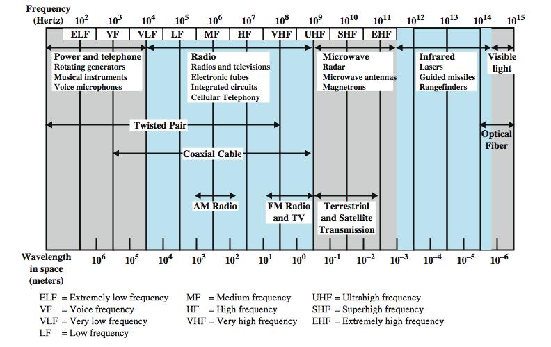
5 Electromagnetic Spectrum

6 The spectrum
7 Electromagnetic Spectrum with Range Specification
8 Transmission Characteristics of Guided Media Twisted pair (with loading) Frequency Range Typical Attenuation 0 to 3.5 khz khz Typical Delay 50 µs/km 2 km Repeater Spacing Twisted pairs (multi-pair cables) 0 to 1 MHz khz Coaxial cable 0 to 500 MHz 7 10 MHz Optical fiber 186 to 370 THz 0.2 to 0.5 db/km 5 µs/km 2 km 4 µs/km 1 to 9 km 5 µs/km 40 km

9 Twisted Pair
10 Twisted Pair - Transmission Characteristics analog needs amplifiers every 5km to 6km digital can use either analog or digital signals needs a repeater every 2-3km limited distance limited bandwidth (1MHz) limited data rate (100MHz) susceptible to interference and noise
11 Unshielded vs Shielded TP unshielded Twisted Pair (UTP) ordinary telephone wire cheapest easiest to install suffers from external EM interference shielded Twisted Pair (STP) metal braid or sheathing that reduces interference more expensive harder to handle (thick, heavy) in a variety of categories - see EIA-568
12 UTP Categories Category 3 Class C Category 5 Class D Category 5E Category 6 Class E Category 7 Class F Bandwidth 16 MHz 100 MHz 100 MHz 200 MHz 600 MHz Cable Type UTP UTP/FTP UTP/FTP UTP/FTP SSTP Link Cost (Cat 5 =1)
13 Comparison of Shielded and Unshielded Twisted Pair Frequency (MHz) Category 3 UTP Attenuation (db per 100 m) Category 5 UTP 150-ohm STP Category 3 UTP Near-end Crosstalk (db) Category 5 UTP 150-ohm STP
14 Near End Crosstalk coupling of signal from one pair to another occurs when transmit signal entering the link couples back to receiving pair ie. near transmitted signal is picked up by near receiving pair
15 Coaxial Cable
16 Coaxial Cable - Transmission Characteristics superior frequency characteristics to TP performance limited by attenuation & noise analog signals amplifiers every few km closer if higher frequency up to 500MHz digital signals repeater every 1km closer for higher data rates

17 Optical Fiber
18 Optical Fiber - Benefits greater capacity data rates of hundreds of Gbps smaller size & weight lower attenuation electromagnetic isolation greater repeater spacing 10s of km at least
19 Optical Fiber - Transmission Characteristics uses total internal reflection to transmit light effectively acts as wave guide for to Hz can use several different light sources Light Emitting Diode (LED) cheaper, wider operating temp range, lasts longer Injection Laser Diode (ILD) more efficient, has greater data rate relation of wavelength, type & data rate

20 Total Internal Reflection

21 Optical Fiber Transmission Modes
22 Dispersion in fiber optic
23 Frequency Utilization for Fiber Applications Wave length (in vacuum) range (nm) Frequency Range (THz) Band Label Fiber Type Application 820 to to 333 Multimode LAN 1280 to to 222 S Single mode Various 1528 to to 192 C Single mode WDM 1561 to to 185 L Single mode WDM

24 Attenuation in Guided Media
25 Comparison: UTP vs. FO Thickness (FO thicker than UTP) Weight (FO 1/100 th of UTP) Photons vs. electrons (Electrons feel more resistance, temperature, hence cross talk. Photons immune to them) Attenuation (FO need amplification after 60km, UTP needs amplification every 5km) Erosion (Copper erode faster, Glass has less environmental effects.
26 Comparison: UTP vs. FO Effect of EM interference (High on UTP and less on FO) Leaking (High risk of eavesdropping and tapping attack in UTP then FO) Bandwidth (Far more in FO then UTP) Cost (FO far more expensive than UTP) Need for skilled engineer (in FO and not in UTP) Technology Complexity (High in FO and easy in UTP) Flexibility ( High in UTP and low in FO)
27 Wireless Transmission Frequencies 2GHz to 40GHz microwave highly directional point to point satellite 30MHz to 1GHz omnidirectional broadcast radio 3 x to 2 x infrared local
28 Antennas electrical conductor used to radiate or collect electromagnetic energy transmission antenna radio frequency energy from transmitter converted to electromagnetic energy byy antenna radiated into surrounding environment reception antenna electromagnetic energy impinging on antenna converted to radio frequency electrical energy fed to receiver same antenna is often used for both purposes
29 Radiation Pattern power radiated in all directions not same performance in all directions as seen in a radiation pattern diagram an isotropic antenna is a (theoretical) point in space radiates in all directions equally with a spherical radiation pattern
30 Parabolic Reflective Antenna
31 Antenna Gain measure of directionality of antenna power output in particular direction verses that produced by an isotropic antenna measured in decibels (db) results in loss in power in another direction effective area relates to size and shape related to gain
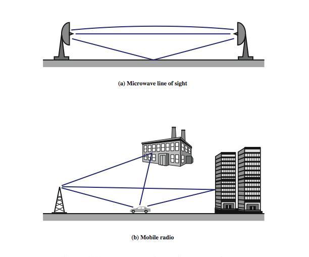
32 Terrestrial Microwave used for long haul telecommunications and short point-to-point links requires fewer repeaters but line of sight use a parabolic dish to focus a narrow beam onto a receiver antenna 1-40GHz frequencies higher frequencies give higher data rates main source of loss is attenuation distance, rainfall also interference
33 Satellite Microwave satellite is relay station receives on one frequency, amplifies or repeats signal and transmits on another frequency eg. uplink GHz & downlink GHz typically requires geo-stationary orbit height of 35,784km spaced at least 3-4 apart typical uses television long distance telephone private business networks global positioning
34 Satellite Point to Point Link
35 Satellite Broadcast Link
36 Broadcast Radio radio is 3kHz to 300GHz use broadcast radio, 30MHz - 1GHz, for: FM radio UHF and VHF television is omnidirectional still need line of sight suffers from multipath interference reflections from land, water, other objects
37 Infrared modulate noncoherent infrared light end line of sight (or reflection) are blocked by walls no licenses required typical uses TV remote control IRD port
38 Wireless Propagation Ground Wave
39 Wireless Propagation Sky Wave
40 Wireless Propagation Line of Sight
41 Refraction velocity of electromagnetic wave is a function of density of material ~3 x 10 8 m/s in vacuum, less in anything else speed changes as move between media Index of refraction (refractive index) is sin(incidence)/sin(refraction) varies with wavelength have gradual bending if medium density varies density of atmosphere decreases with height results in bending towards earth of radio waves hence optical and radio horizons differ
42 Line of Sight Transmission Free space loss loss of signal with distance Atmospheric Absorption from water vapour and oxygen absorption Multipath multiple interfering signals from reflections Refraction bending signal away from receiver

43 Free Space Loss
44 Multipath Interference
45 Fiber Optics v/s Satellite Wire v/s Practically? Single fiber has, more potential bandwidth than all the satellites ever launched but, this bandwidth is not available to most users practically. Wireless With satellites, it is practical for a user to erect an antenna on the roof of the building and completely bypass wired system to get high bandwidth. Mobile Communication? satellite links Terrestrial fiber optic links potentially are most are of no use to them. suitable for mobile communication. By:Bhargavi_H._Goswami, bhargavigoswami@gmail.com 45
46 Fiber Optics v/s Satellite Wire v/s Broadcasting? Not suitable for broadcasting. Cost? Costly for communication in places with hostile terrain or a poorly developed terrestrial infrastructure. Right of Way? for laying fiber is difficult or unduly expensive. Rapid Deployment? Fiber optics is costly in terms of skilled engineers. Wireless Message sent by satellite can be received by thousands of ground stations at once. Best suited. Launching one satellite was cheaper than stringing thousands of undersea cables among the 13,677 islands. Instead launching one satellite would be cheaper. When rapid deployment is critical, as in military communication systems in time of war, satellites win easily By:Bhargavi_H._Goswami, bhargavigoswami@gmail.com 46
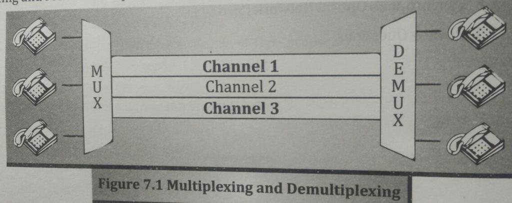
47 MULTIPLEXING MUX DEMUX TYPES FREQUENCY DIVISION MULTIPLEXING TIME DIVISION MULTIPLEXING ASYNCHRONOUS V/S SYNCHRONOUS TDM WAVELENGTH DIVISION MULTIPLEXING SONET MULTIPLEXING (SYNCHRONOUS OPTICAL NETWORK MULTIPLEXING)
48

49
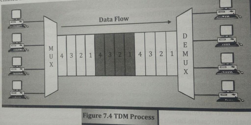
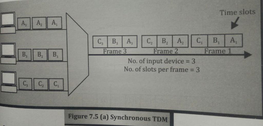
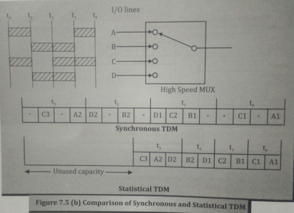
50 TDM SYNCHRONOUS TDM ASYNCHRONOUS/ INTELLIGENT/ STATISTICAL TDM
51
52
53

54 WDM Wavelength Division Multiplexing
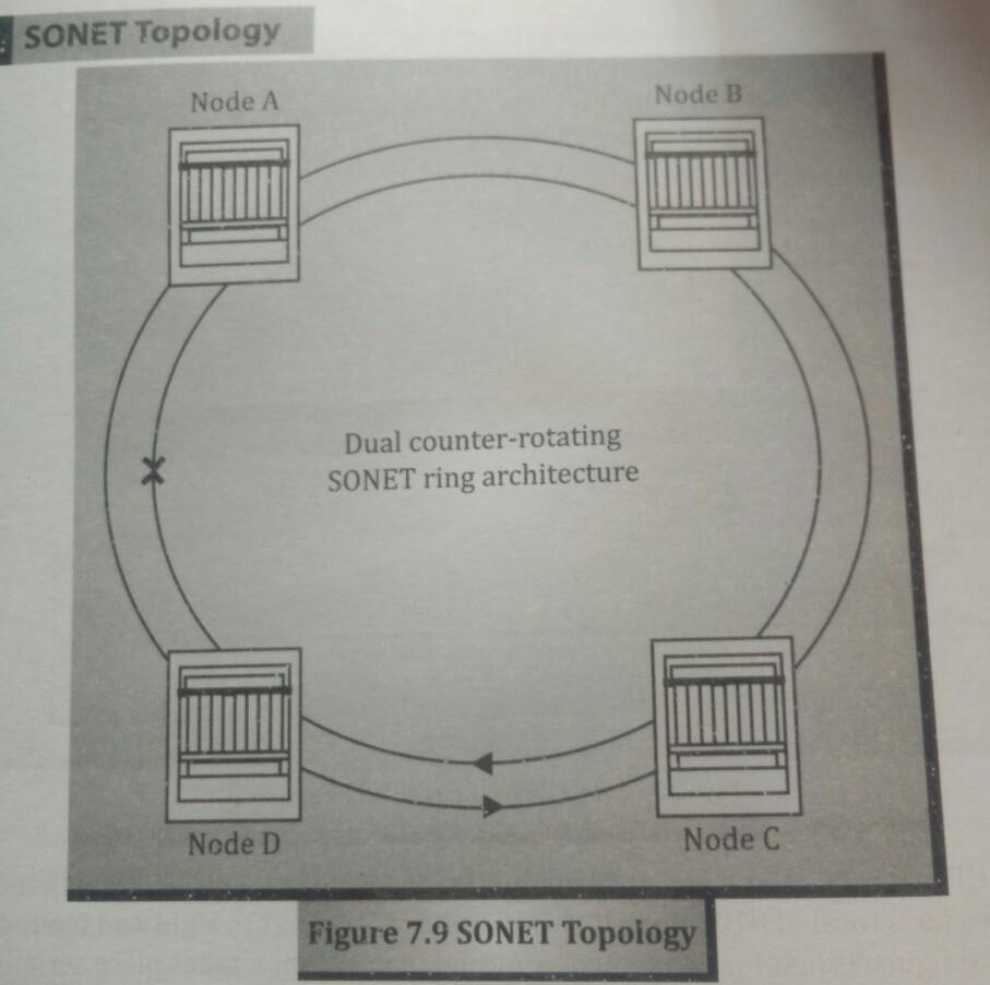
55 SONET Synchronous Optical Network Is an Optical Transmission Interface having synchronous network. Proposed by Bellcore and standardized by ANSI. Used in North America, while Japan and Europe uses SDH Synchronous Digital Hierarchy. Solved issue of interoperability among the vendors and technology. Single clock is used to handle the timings. Used for Broadcast services, particularly ATM and B-ISDN.

56 Synchronous Transport Signal
57 PHYSICAL CONFIGURATION STS Multiplexers Regenerators Add/Drop Multiplexers
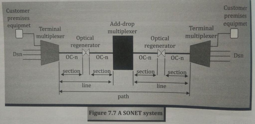
58 Physical Configuration
59
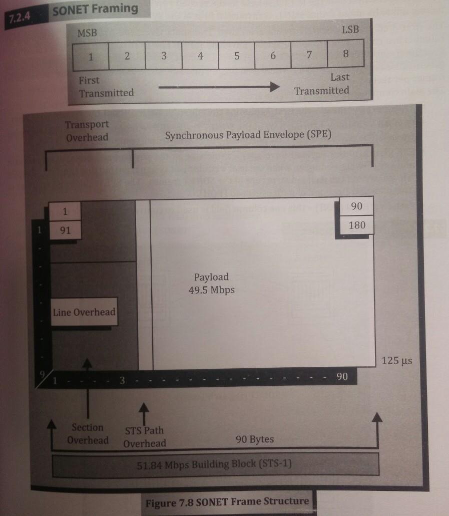
60 Frame Structure Has 9 rows of 90 bytes i.e 9x90=810 bytes. Transmitted from left to right and top to bottom. TOH First three columns are called Transport Overhead. SPE Remaining 87 columns are called Synchronous Payload Envelop POH First column of SPE is called Payload Overhead. Every SONET Frame repeats every 125 microseconds no matter what is line speed. As line rate goes up, SONET frame gets bigger, to keep frame rate at 8000 frames/sec.
61
62 CIRCUIT SWITCHING MULTISTAGE CROSSBAR

63 CROSSBAR SWITCH

64 MULTI STAGE SWITCH
65 ERROR DETECTION AND CORRECTION TYPES OF ERRORS BIT STUFFING BYTE STUFFING BURST ERRORS VRC LRC CRC HAMMING CODE CHECKSUM
66 Types of Errors: By: Prof. Bhargavi Goswami, Mob:
67 Single-bit error By: Prof. Bhargavi Goswami, Mob:
68 Multiple-bit error By: Prof. Bhargavi Goswami, Mob:

69 Burst error By: Prof. Bhargavi Goswami, Mob:
70 XORing of two single bits or two words To detect or correct errors, we need to send extra (redundant) bits with data. By: Prof. Bhargavi Goswami, Mob:
71 Detection Methods: Detection methods VRC(Vertical Redundancy Check) LRC(Longitudinal Redundancy) CRC(Cyclical redundancy Check) Checksum By: Prof. Bhargavi Goswami, Mob:
72 VRC VRC(Vertical Redundancy Check) A parity bit is added to every data unit so that the total number of 1s(including the parity bit) becomes even for even-parity check or odd for odd-parity check VRC can detect all single-bit errors. It can detect multiple-bit or burst errors only the total number of errors is odd. Even parity VRC concept is given in next fig By: Prof. Bhargavi Goswami, bhargavigoswami@gmail.com, Mob:

73 VRC By: Prof. Bhargavi Goswami, Mob:
74 LRC LRC(Longitudinal Redundancy Check) Parity bits of all the positions are assembled into a new data unit, which is added to the end of the data block By: Prof. Bhargavi Goswami, bhargavigoswami@gmail.com, Mob:
75 VRC & LRC By: Prof. Bhargavi Goswami, Mob:
76 CRC Generator CRC generator uses modular-2 division. Binary Division in a CRC Generator
77 CRC Checker Binary Division in a CRC Checker By: Prof. Bhargavi Goswami, bhargavigoswami@gmail.com, Mob:
78 As per text book: Calculation of the polynomial code checksum. By: Prof. Bhargavi Goswami, Mob:
79 Checksum: Checksum is used by the higher layer protocols And is based on the concept of redundancy(vrc, LRC, CRC. Hamming code) To create the checksum the sender does the following: The unit is divided into K sections, each of n bits. Section 1 and 2 are added together using one s complement. Section 3 is added to the result of the previous step. Section 4 is added to the result of the previous step. The process repeats until section k is added to the result of the previous step. The final result is complemented to make the checksum.

80 Checksum Example
81 Hamming code and Error Redundancy for error handling m data bits and r redundant bits for m + r bits only one correct value of r for a given m one correct bit pattern requires m + r incorrect patterns m + r + 1 < 2 r 7 bit data 4 bit redundant bits makes it 11
82 Hamming code calculations
83 R1,R2,R3 and R4 calculations R1 represents the parity of M1, M2, M4, M5, and M7 = M1 + M2 + M4 + M5 + M7 = = 0 R2 represents the parity of M1, M3, M4, M6, and M7 = =0 R3 represents the parity of M2, M3, and M4=1 R4 represents the parity of M5, M6, and M7=0

84 Error Correction Using Hamming Code can be handled in two ways: when an error is discovered, the receiver can have the sender retransmit the entire data unit. a receiver can use an error-correcting code, which automatically corrects certain errors. Hamming Code ~ developed by R.W. Hamming positions of redundancy bits in Hamming code, lets see how. each r bit is the VRC bit for one combination of data bits r 1 = bits 1, 3, 5, 7, 9, 11 r 2 = bits 2, 3, 6, 7, 10, 11 r 4 = bits 4, 5, 6, 7 r 8 = bits 8, 9, 10, 11

85 Redundant Bit Position By: Prof. Bhargavi Goswami, Mob:
86
87 By: Prof. Bhargavi Goswami, Mob:
88 Calculating the r values Calculating Even Parity
89 Example:

90 Error Detection Using Hamming Code:
91 Start preparation for final exam. THANK YOU
William Stallings Data and Computer Communications 7 th Edition. Chapter 4 Transmission Media
 William Stallings Data and Computer Communications 7 th Edition Chapter 4 Transmission Media Overview Guided - wire Unguided - wireless Characteristics and quality determined by medium and signal For guided,
William Stallings Data and Computer Communications. Bab 4 Media Transmisi
 William Stallings Data and Computer Communications Bab 4 Media Transmisi Overview Guided - wire Unguided - wireless Characteristics and quality determined by medium and signal For guided, the medium is
Data and Computer Communications Chapter 4 Transmission Media
 Data and Computer Communications Chapter 4 Transmission Media Ninth Edition by William Stallings Data and Computer Communications, Ninth Edition by William Stallings, (c) Pearson Education - Prentice Hall,
Chapter 4: Transmission Media
 Chapter 4: Transmission Media Page 1 Overview Guided - wire Unguided - wireless Characteristics and quality determined by medium and signal For guided, the medium is more important For unguided, the bandwidth
CS311 -Data Communication Unguided Transmission Media
 CS311 -Data Communication Unguided Transmission Media Dr. Manas Khatua Assistant Professor Dept. of CSE IIT Jodhpur E-mail: manaskhatua@iitj.ac.in INTRODUCTION -Physical Path between transmitter and receiver
Unguided Transmission Media
 CS311 Data Communication Unguided Transmission Media by Dr. Manas Khatua Assistant Professor Dept. of CSE IIT Jodhpur E-mail: manaskhatua@iitj.ac.in Web: http://home.iitj.ac.in/~manaskhatua http://manaskhatua.github.io/
DATA TRANSMISSION. ermtiong. ermtiong
 DATA TRANSMISSION Analog Transmission Analog signal transmitted without regard to content May be analog or digital data Attenuated over distance Use amplifiers to boost signal Also amplifies noise DATA
Data and Computer Communications. Tenth Edition by William Stallings
 Data and Computer Communications Tenth Edition by William Stallings Data and Computer Communications, Tenth Edition by William Stallings, (c) Pearson Education - Prentice Hall, 2013 Wireless Transmission
Overview. Chapter 4. Design Factors. Electromagnetic Spectrum
 Chapter 4 Transmission Media Overview Guided - wire Unguided - wireless Characteristics and quality determined by medium and signal For guided, the medium is more important For unguided, the bandwidth
Transmission Media. Transmission Media 12/14/2016
 Transmission Media in data communications DDE University of Kashmir By Suhail Qadir System Analyst suhailmir@uok.edu.in Transmission Media the transmission medium is the physical path between transmitter
Module 2. Studoob.in - Where Learning is Entertainment
 Module 2 Module 2 Transmission media - Guided Transmission Media: Twisted pair, Coaxial cable, optical fiber, Wireless Transmission, Terrestrial microwave, Satellite microwave. Wireless Propagation: Ground
Computer Networks Lecture -4- Transmission Media. Dr. Methaq Talib
 Computer Networks Lecture -4- Transmission Media Dr. Methaq Talib Transmission Media A transmission medium can be broadly defined as anything that can carry information from a source to a destination.
Transmission Medium/ Media
 Transmission Medium/ Media The successful transmission of data depends principally on two factors: the quality of the signal being transmitted and the characteristics of the transmission medium Transmission
Class 4 ((Communication and Computer Networks))
)") Class 4 ((Communication and Computer Networks)) Lesson 3... Transmission Media, Part 1 Abstract The successful transmission of data depends principally on two factors: the quality of the signal being transmitted
Class 4 ((Communication and Computer Networks)) Lesson 3... Transmission Media, Part 1 Abstract The successful transmission of data depends principally on two factors: the quality of the signal being transmitted
Contents. ITS323: Introduction to Data Communications CSS331: Fundamentals of Data Communications. Transmission Media and Spectrum.
 2 ITS323: Introduction to Data Communications CSS331: Fundamentals of Data Communications Sirindhorn International Institute of Technology Thammasat University Prepared by Steven Gordon on 3 August 2015
ITS323: Introduction to Data Communications CSS331: Fundamentals of Data Communications
 ITS323: Introduction to Data Communications CSS331: Fundamentals of Data Communications Sirindhorn International Institute of Technology Thammasat University Prepared by Steven Gordon on 3 August 2015
Transmission Media. - Bounded/Guided Media - Uubounded/Unguided Media. Bounded Media
 Transmission Media The means through which data is transformed from one place to another is called transmission or communication media. There are two categories of transmission media used in computer communications.
Unguided Media and Matched Filter After this lecture, you will be able to Example?
 Unguided Media and Matched Filter After this lecture, you will be able to describe the physical and transmission characteristics of various unguided media Example? B.1 Unguided media Guided to unguided
Transmission Media. Two main groups:
 Transmission Media Two main groups: -Wire based media (hardwire, or guided), either : -electric, like twisted pair cable TP, coaxial cable -optic, like fiber optics -Wireless (softwire, or unguided), like
TRANSMISSION MEDIA CHAPTER Guided Transmission Media. 4.2 Wireless Transmission. 4.3 Wireless Propagation. 4.4 Line-of-Sight Transmission
 TRANSMISSION MEDIA CHAPTER4 4.1 Guided Transmission Media 4.2 Wireless Transmission 4.3 Wireless Propagation 4.4 Line-of-Sight Transmission 4.5 Recommended Reading and Web Sites 4.6 Key Terms, Review Questions,
Maximum date rate=2hlog 2 V bits/sec. Maximum number of bits/sec=hlog 2 (1+S/N)
") Basics Data can be analog or digital. The term analog data refers to information that is continuous, digital data refers to information that has discrete states. Analog data take on continuous values.
Basics Data can be analog or digital. The term analog data refers to information that is continuous, digital data refers to information that has discrete states. Analog data take on continuous values.
Figure 4-1. Figure 4-2 Classes of Transmission Media
 Electromagnetic Spectrum Chapter 4 Transmission Media Computers and other telecommunication devices transmit signals in the form of electromagnetic energy, which can be in the form of electrical current,
Transmission Media. Beulah A L/CSE. 2 July 2008 Transmission Media Beulah A. 1
 Transmission Media Beulah A L/CSE 2 July 2008 Transmission Media Beulah A. 1 Guided Transmission Media Magnetic Media A tape can hold 7 gigabytes. A box can hold about 1000 tapes. Assume a box can be delivered
Department Of Computer Science ASSAM UNIVERSITY, SILCHAR
 Department Of Computer Science ASSAM UNIVERSITY, SILCHAR Submitted By Submitted To: Mrinal Kanti Paul Mr. B.S. Mena 6 th Semester Roll No.: 03 Transmission Media: Sender Physical Layer Physical Layer Receiver
Local Networks. Lecture 2 23-Mar-2016
 Local Networks Lecture 2 23-Mar-2016 Roadmap of the course Last time LAN and networking introduction Models for data communication Data transmission issues Today Transmission media Error detection methods
In this section of my blog, I will be discussing different transmission methods and why those particular methods are used in particular situations:
 In this section of my blog, I will be discussing different transmission methods and why those particular methods are used in particular situations: Transmission Methods are a variety of different methods
Physical-Layer Services and Systems
 Physical-Layer Services and Systems Figure Transmission medium and physical layer Figure Classes of transmission media GUIDED MEDIA Guided media, which are those that provide a conduit from one device
Antennas & Propagation. CSG 250 Fall 2007 Rajmohan Rajaraman
 Antennas & Propagation CSG 250 Fall 2007 Rajmohan Rajaraman Introduction An antenna is an electrical conductor or system of conductors o Transmission - radiates electromagnetic energy into space o Reception
Media. Twisted pair db/km at 1MHz 2 km. Coaxial cable 7 db/km at 10 MHz 1 9 km. Optical fibre 0.2 db/km 100 km
 Media Attenuation Repeater spacing Twisted pair 10-12 db/km at 1MHz 2 km Coaxial cable 7 db/km at 10 MHz 1 9 km Optical fibre 0.2 db/km 100 km conniq.com provides an excellent tutorial on physical media.
Point-to-Point Communications
 Point-to-Point Communications Key Aspects of Communication Voice Mail Tones Alphabet Signals Air Paper Media Language English/Hindi English/Hindi Outline of Point-to-Point Communication 1. Signals basic
UNIT-1. Basic signal processing operations in digital communication
 UNIT-1 Lecture-1 Basic signal processing operations in digital communication The three basic elements of every communication systems are Transmitter, Receiver and Channel. The Overall purpose of this system
Introduction to LAN/WAN. Physical Layer
 Introduction to LAN/WAN Physical Layer Topics Introduction Theory Transmission Media Purpose of Physical Layer Transport bits between machines How do we send 0's and 1's across a medium? Ans: vary physical
Chapter-1: Introduction
 Chapter-1: Introduction The purpose of a Communication System is to transport an information bearing signal from a source to a user destination via a communication channel. MODEL OF A COMMUNICATION SYSTEM
Data Communication Prof. Ajit Pal Department of Computer Science & Engineering Indian Institute of Technology, Kharagpur Lecture No # 6 Unguided Media
 Data Communication Prof. Ajit Pal Department of Computer Science & Engineering Indian Institute of Technology, Kharagpur Lecture No # 6 Unguided Media Hello and welcome to today s lecture on unguided media.
Last Time. Transferring Information. Today (& Tomorrow (& Tmrw)) Application Layer Example Protocols ftp http Performance.
) Application Layer Example Protocols ftp http Performance.") 15-441 Lecture 5 Last Time Physical Layer & Link Layer Basics Copyright Seth Goldstein, 2008 Application Layer Example Protocols ftp http Performance Application Presentation Session Transport Network
15-441 Lecture 5 Last Time Physical Layer & Link Layer Basics Copyright Seth Goldstein, 2008 Application Layer Example Protocols ftp http Performance Application Presentation Session Transport Network
Lecture 5 Transmission
 Lecture 5 Transmission David Andersen Department of Computer Science Carnegie Mellon University 15-441 Networking, Spring 2005 http://www.cs.cmu.edu/~srini/15-441/s05 1 Physical and Datalink Layers: 3
E-716-A Mobile Communications Systems. Lecture #2 Basic Concepts of Wireless Transmission (p1) Instructor: Dr. Ahmad El-Banna
 Instructor: Dr. Ahmad El-Banna") October 2014 Ahmad El-Banna Integrated Technical Education Cluster At AlAmeeria E-716-A Mobile Communications Systems Lecture #2 Basic Concepts of Wireless Transmission (p1) Instructor: Dr. Ahmad El-Banna
October 2014 Ahmad El-Banna Integrated Technical Education Cluster At AlAmeeria E-716-A Mobile Communications Systems Lecture #2 Basic Concepts of Wireless Transmission (p1) Instructor: Dr. Ahmad El-Banna
Lecture 3: Transmission Media
 Lecture 3: Transmission Media Dr. Mohd Nazri Bin Mohd Warip High Performance Broadband Networks Research Group Embedded, Networks and Advanced Computing Research Cluster School of Computer and Communication
Books: 1. Data communications by William L Schweber 2. Data communication and Networking by Behrouz A F0rouzan
 Books: 1. Data communications by William L Schweber 2. Data communication and Networking by Behrouz A F0rouzan Twisted Pair cable Multiconductor flat cable Advantages of Twisted Pair Cable Simplest to
Chapter-15. Communication systems -1 mark Questions
 Chapter-15 Communication systems -1 mark Questions 1) What are the three main units of a Communication System? 2) What is meant by Bandwidth of transmission? 3) What is a transducer? Give an example. 4)
LE/EECS 3213 Fall Sebastian Magierowski York University. EECS 3213, F14 L8: Physical Media
 LE/EECS 3213 Fall 2014 L8: Physical Media Properties Sebastian Magierowski York University 1 Key characteristics of physical media What signals in media are made out of Delay through media Attenuation
Antennas and Propagation. Chapter 5
 Antennas and Propagation Chapter 5 Introduction An antenna is an electrical conductor or system of conductors Transmission - radiates electromagnetic energy into space Reception - collects electromagnetic
Lecture 3: The Physical Layer and Transmission Media
 Lecture 3: The Physical Layer and Transmission Media Dr. Mohammed Hawa Electrical Engineering Department University of Jordan EE426: Communication Networks The Physical Layer Converts bit streams into
Chapter 1 Introduction
 Wireless Information Transmission System Lab. Chapter 1 Introduction National Sun Yat-sen University Table of Contents Elements of a Digital Communication System Communication Channels and Their Wire-line
Antennas and Propagation
 Antennas and Propagation Chapter 5 Introduction An antenna is an electrical conductor or system of conductors Transmission - radiates electromagnetic energy into space Reception - collects electromagnetic
Data and Computer Communications. Tenth Edition by William Stallings
 Data and Computer Communications Tenth Edition by William Stallings Data and Computer Communications, Tenth Edition by William Stallings, (c) Pearson Education - Prentice Hall, 2013 CHAPTER 8 Multiplexing
Lecture 5 Transmission. Physical and Datalink Layers: 3 Lectures
 Lecture 5 Transmission Peter Steenkiste School of Computer Science Department of Electrical and Computer Engineering Carnegie Mellon University 15-441 Networking, Spring 2004 http://www.cs.cmu.edu/~prs/15-441
Mobile and Wireless Networks Course Instructor: Dr. Safdar Ali
 Mobile and Wireless Networks Course Instructor: Dr. Safdar Ali BOOKS Text Book: William Stallings, Wireless Communications and Networks, Pearson Hall, 2002. BOOKS Reference Books: Sumit Kasera, Nishit
Antennas and Propagation. Chapter 5
 Antennas and Propagation Chapter 5 Introduction An antenna is an electrical conductor or system of conductors Transmission - radiates electromagnetic energy into space Reception - collects electromagnetic
Computer Networks
 15-441 Computer Networks Physical Layer Professor Hui Zhang hzhang@cs.cmu.edu 1 Communication & Physical Medium There were communications before computers There were communication networks before computer
Data Communication & Networking CSCI Dr. Thomas Hicks Computer Science Department Trinity University 1
 Data Communication & Networking CSCI 3342 Dr. Thomas Hicks Computer Science Department Trinity University 1 1 Must Consider Protocols 2 Protocols http://www.networksorcery.com/enp/protocol.htm http://www.networksorcery.com/enp/topic/ipsuite.htm
CHAPTER -15. Communication Systems
 CHAPTER -15 Communication Systems COMMUNICATION Communication is the act of transmission and reception of information. COMMUNICATION SYSTEM: A system comprises of transmitter, communication channel and
The Physical Layer Outline
 The Physical Layer Outline Theoretical Basis for Data Communications Digital Modulation and Multiplexing Guided Transmission Media (copper and fiber) Public Switched Telephone Network and DSLbased Broadband
Chapter 4: Physical Layer
 What are the Duties of physical layer? Machine port level addressing Transferring bits Synchronizing the sender and receiver Multiplexing multiple data streams Chapter 4: Physical Layer Machine port level
EE 304 TELECOMMUNICATIONs ESSENTIALS HOMEWORK QUESTIONS AND ANSWERS
 Homework Question 1 EE 304 TELECOMMUNICATIONs ESSENTIALS HOMEWORK QUESTIONS AND ANSWERS Allocated channel bandwidth for commercial TV is 6 MHz. a. Find the maximum number of analog voice channels that
COMMUNICATION SYSTEMS -I
 COMMUNICATION SYSTEMS -I Communication : It is the act of transmission of information. ELEMENTS OF A COMMUNICATION SYSTEM TRANSMITTER MEDIUM/CHANNEL: The physical medium that connects transmitter to receiver
Antennas and Propagation
 Mobile Networks Module D-1 Antennas and Propagation 1. Introduction 2. Propagation modes 3. Line-of-sight transmission 4. Fading Slides adapted from Stallings, Wireless Communications & Networks, Second
UNIT 2 DATA TRANSMISSION
 Introduction to Data Communication and Computer Network Concepts UNIT 2 DATA TRANSMISSION Structure Nos. Page 2.0 Introduction 44 2.1 Objectives 45 2.2 Data Communication Terminology 45 2.2.1 Channel 2.2.2
INTRODUCTION TO COMMUNICATION SYSTEMS AND TRANSMISSION MEDIA
 COMM.ENG INTRODUCTION TO COMMUNICATION SYSTEMS AND TRANSMISSION MEDIA 9/9/2017 LECTURES 1 Objectives To give a background on Communication system components and channels (media) A distinction between analogue
Antenna & Propagation. Basic Radio Wave Propagation
 For updated version, please click on http://ocw.ump.edu.my Antenna & Propagation Basic Radio Wave Propagation by Nor Hadzfizah Binti Mohd Radi Faculty of Electric & Electronics Engineering hadzfizah@ump.edu.my
Antennas and Propagation
 CMPE 477 Wireless and Mobile Networks Lecture 3: Antennas and Propagation Antennas Propagation Modes Line of Sight Transmission Fading in the Mobile Environment Introduction An antenna is an electrical
Chapter 2. Physical Layer
 Chapter 2 Physical Layer Lecture 1 Outline 2.1 Analog and Digital 2.2 Transmission Media 2.3 Digital Modulation and Multiplexing 2.4 Transmission Impairment 2.5 Data-rate Limits 2.6 Performance Physical
Communications II. Mohammad Fathi Text book: J.G. Proakis and M. Salehi, Communication System Engineering (2 nd Ed) Syllabus
 Syllabus") Communications II Mohammad Fathi mfathi@uok.ac.ir Course information Text book: J.G. Proakis and M. Salehi, Communication System Engineering (2 nd Ed) Syllabus Introduction: [1.1, 1.2, 1.3, and 1.4] Review
Communications II Mohammad Fathi mfathi@uok.ac.ir Course information Text book: J.G. Proakis and M. Salehi, Communication System Engineering (2 nd Ed) Syllabus Introduction: [1.1, 1.2, 1.3, and 1.4] Review
COMP211 Physical Layer
 COMP211 Physical Layer Data and Computer Communications 7th edition William Stallings Prentice Hall 2004 Computer Networks 5th edition Andrew S.Tanenbaum, David J.Wetherall Pearson 2011 Material adapted
Thursday, April 17, 2008, 6:28:40
 Wavelength Division Multiplexing By: Gurudatha Pai K gurudatha@gmail.com Thursday, April 17, 2008, 6:28:40 Overview Introduction Popular Multiplexing Techniques Optical Networking WDM An Analogy of Multiplexing
Lecture 3: Data Transmission
 Lecture 3: Data Transmission 1 st semester 1439-2017 1 By: Elham Sunbu OUTLINE Data Transmission DATA RATE LIMITS Transmission Impairments Examples DATA TRANSMISSION The successful transmission of data
Jaringan Komputer. Outline. The Physical Layer
 Jaringan Komputer The Physical Layer Outline Defines the mechanical, electrical, and timing interfaces to the network Theoretical analysis of data transmission Kinds of transmission media Examples: the
ECE 271 INTRODUCTION TO TELECOMMUNICATION NETWORKS HOMEWORK QUESTIONS ECE 271 HOMEWORK-1
 ECE 271 INTRODUCTION TO TELECOMMUNICATION NETWORKS HOMEWORK QUESTIONS Homework Question 1 ECE 271 HOMEWORK-1 Allocated channel bandwidth for commercial TV is 6 MHz. a. Find the maximum number of analog
CPSC Network Programming. How do computers really communicate?
 CPSC 360 - Network Programming Data Transmission Michele Weigle Department of Computer Science Clemson University mweigle@cs.clemson.edu February 11, 2005 http://www.cs.clemson.edu/~mweigle/courses/cpsc360
C05a: Transmission Media
 CISC 7332X T6 C05a: Transmission Media Hui Chen Department of Computer & Information Science CUNY Brooklyn College 9/25/2018 CUNY Brooklyn College 1 Review Discussed Overview and network applications Application
DDPP 2163 Propagation Systems. Satellite Communication
 DDPP 2163 Propagation Systems Satellite Communication 1 Satellite Two far apart stations can use a satellite as a relay station for their communication It is possible because the earth is a sphere. Radio
is a method of transmitting information from one place to another by sending light through an optical fiber. The light forms an electromagnetic
 is a method of transmitting information from one place to another by sending light through an optical fiber. The light forms an electromagnetic carrier wave that is modulated to carry information. The
CS441 Mobile & Wireless Computing Communication Basics
 Department of Computer Science Southern Illinois University Carbondale CS441 Mobile & Wireless Computing Communication Basics Dr. Kemal Akkaya E-mail: kemal@cs.siu.edu Kemal Akkaya Mobile & Wireless Computing
ECE 435 Network Engineering Lecture 16
 ECE 435 Network Engineering Lecture 16 Vince Weaver http://web.eece.maine.edu/~vweaver vincent.weaver@maine.edu 1 November 2018 Announcements No homework this week. Demo of infiniband / fiber / ethernet
Announcements : Wireless Networks Lecture 3: Physical Layer. Bird s Eye View. Outline. Page 1
 Announcements 18-759: Wireless Networks Lecture 3: Physical Layer Please start to form project teams» Updated project handout is available on the web site Also start to form teams for surveys» Send mail
PRINCIPLES OF COMMUNICATION SYSTEMS. Lecture 1- Introduction Elements, Modulation, Demodulation, Frequency Spectrum
 PRINCIPLES OF COMMUNICATION SYSTEMS Lecture 1- Introduction Elements, Modulation, Demodulation, Frequency Spectrum Topic covered Introduction to subject Elements of Communication system Modulation General
Data and Computer Communications. Chapter 3 Data Transmission
 Data and Computer Communications Chapter 3 Data Transmission Data Transmission quality of the signal being transmitted The successful transmission of data depends on two factors: characteristics of the
Outline of the Lecture
 CS311: DATA COMMUNICATION Multiplexing by Dr. Manas Khatua Assistant Professor Dept. of CSE IIT Jodhpur E-mail: manaskhatua@iitj.ac.in Web: http://home.iitj.ac.in/~manaskhatua http://manaskhatua.github.io/
Lecture 1: Introduction
 Optical Fibre Communication Systems Lecture 1: Introduction Professor Z Ghassemlooy Electronics & It Division School of Engineering Sheffield Hallam University U.K. www.shu.ac.uk/ocr 1 Contents Reading
Data and Computer Communications Chapter 3 Data Transmission
 Data and Computer Communications Chapter 3 Data Transmission Eighth Edition by William Stallings Transmission Terminology data transmission occurs between a transmitter & receiver via some medium guided
Chapter 4: Practical Communication Systems. 18/09/2016 Nurul/DEE 3413/Practical Com System 1
 Chapter 4: Practical Communication Systems 18/09/2016 Nurul/DEE 3413/Practical Com System 1 Outline Fibre Optic Communication System Telephone System Radio Communication System Satellite Communication
Optical networking. Emilie CAMISARD GIP RENATER Optical technologies engineer Advanced IP Services
 Optical networking Emilie CAMISARD GIP RENATER Optical technologies engineer Advanced IP Services Agenda Optical fibre principle Time Division Multiplexing (TDM) Wavelength Division Multiplexing (WDM)
Vehicle Networks. Wireless communication basics. Univ.-Prof. Dr. Thomas Strang, Dipl.-Inform. Matthias Röckl
 Vehicle Networks Wireless communication basics Univ.-Prof. Dr. Thomas Strang, Dipl.-Inform. Matthias Röckl Outline Wireless Signal Propagation Electro-magnetic waves Signal impairments Attenuation Distortion
ECE 435 Network Engineering Lecture 20
 ECE 435 Network Engineering Lecture 20 Vince Weaver http://web.eece.maine.edu/~vweaver vincent.weaver@maine.edu 16 November 2017 Announcements SC 17 takeaway Lots of network stuff there, the network being
Bandwidth Utilization:
 CHAPTER 6 Bandwidth Utilization: In real life, we have links with limited bandwidths. The wise use of these bandwidths has been, and will be, one of the main challenges of electronic communications. However,
EC 554 Data Communications
 EC 554 Data Communications Mohamed Khedr http://webmail. webmail.aast.edu/~khedraast.edu/~khedr Syllabus Tentatively Week 1 Week 2 Week 3 Week 4 Week 5 Week 6 Week 7 Week 8 Week 9 Week 10 Week 11 Week
MODULE IV. End Sem. Exam Marks. Syllabus
 MODULE IV Syllabus Multiplexing- Space Division Multiplexing, Frequency Division Multiplexing, Wave length Division Multiplexing - Time Division multiplexing: Characteristics, Digital Carrier system, SONET/SDH,
a. Find the minimum number of samples per second needed to recover the signal without loosing information.
 1. The digital signal X(t) given below. X(t) 1 0 1 2 3 4 5 7 8 t (msec) a. If the carrier is sin (2000 π t), plot Amplitude Shift Keying (ASK) Modulated signal. b. If digital level 1 is represented by
Multiplexing. Dr. Manas Khatua Assistant Professor Dept. of CSE IIT Jodhpur
 CS311: DATA COMMUNICATION Multiplexing Dr. Manas Khatua Assistant Professor Dept. of CSE IIT Jodhpur e-mail: manaskhatua@iitj.ac.in Outline of the Lecture What is Multiplexing and why is it used? Basic
Question Paper Profile
 Question Paper Profile Max. Marks : 70 Time: 3 Hrs. Q.1) A) Attempt any FIVE of the following. 10 Marks a) Define the term Standard. State its two categories. b) List any two advantages of Unguided Media.
Terminology (1) Chapter 3. Terminology (3) Terminology (2) Transmitter Receiver Medium. Data Transmission. Direct link. Point-to-point.
 Chapter 3. Terminology (3) Terminology (2) Transmitter Receiver Medium. Data Transmission. Direct link. Point-to-point.") Terminology (1) Chapter 3 Data Transmission Transmitter Receiver Medium Guided medium e.g. twisted pair, optical fiber Unguided medium e.g. air, water, vacuum Spring 2012 03-1 Spring 2012 03-2 Terminology
Terminology (1) Chapter 3 Data Transmission Transmitter Receiver Medium Guided medium e.g. twisted pair, optical fiber Unguided medium e.g. air, water, vacuum Spring 2012 03-1 Spring 2012 03-2 Terminology
Introduction to Telecommunications and Computer Engineering Unit 3: Communications Systems & Signals
 Introduction to Telecommunications and Computer Engineering Unit 3: Communications Systems & Signals Syedur Rahman Lecturer, CSE Department North South University syedur.rahman@wolfson.oxon.org Acknowledgements
Chapter 3. Data Transmission
 Chapter 3 Data Transmission Reading Materials Data and Computer Communications, William Stallings Terminology (1) Transmitter Receiver Medium Guided medium (e.g. twisted pair, optical fiber) Unguided medium
Session2 Antennas and Propagation
 Wireless Communication Presented by Dr. Mahmoud Daneshvar Session2 Antennas and Propagation 1. Introduction Types of Anttenas Free space Propagation 2. Propagation modes 3. Transmission Problems 4. Fading
CHAPTER ONE INTRODUCTION
 CHAPTER ONE INTRODUCTION 1.1 Background A communication system transmits information from one place to another, whether separated by a few kilometers or by transoceanic distances. Information is often
Lectureo5 FIBRE OPTICS. Unit-03
 Lectureo5 FIBRE OPTICS Unit-03 INTRODUCTION FUNDAMENTAL IDEAS ABOUT OPTICAL FIBRE Multimode Fibres Multimode Step Index Fibres Multimode Graded Index Fibres INTRODUCTION In communication systems, there
Chapter 2: Computer Networks
 Chapter 2: Computer Networks 2.1: Physical Layer: representation of digital signals 2.2: Data Link Layer: error protection and access control 2.3: Network infrastructure 2.4 2.5: Local Area Network examples
Data Communication. Chapter 3 Data Transmission
 Data Communication Chapter 3 Data Transmission ١ Terminology (1) Transmitter Receiver Medium Guided medium e.g. twisted pair, coaxial cable, optical fiber Unguided medium e.g. air, water, vacuum ٢ Terminology
Chapter 2 Transmission Media and Propagation Mechanisms
 Chapter 2 Transmission Media and Propagation Mechanisms 2.1 Introduction Signals generated by the source need to be transported to the destination over a communication s channel. A communication channel
Data and Computer Communications. Tenth Edition by William Stallings
 Data and Computer Communications Tenth Edition by William Stallings Data and Computer Communications, Tenth Edition by William Stallings, (c) Pearson Education, 2013 CHAPTER 8 Multiplexing It was impossible