Transmission Media. Two main groups:
|
|
|
- Eleanor Fletcher
- 5 years ago
- Views:
Transcription
1 Transmission Media Two main groups: -Wire based media (hardwire, or guided), either : -electric, like twisted pair cable TP, coaxial cable -optic, like fiber optics -Wireless (softwire, or unguided), like infrared rays, radio waves, microwaves. Characteristics and quality determined by medium and used signal. For guided media (wire based), the medium is more important! For unguided media, the bandwidth produced by the antenna is more important! Main key concerns are: data rate & distance 11/27/2018 Vasile Dadarlat - Computer Networks 1


2 Electromagnetic Spectrum & used frequencies by each media s transmission technique 11/27/2018 Vasile Dadarlat - Computer Networks 2
3 Design Factors Bandwidth Higher bandwidth gives higher data rate Transmission impairments Attenuation limits possible covered distances (acts more for guided media) Interference (acts on both categories); for guided media use of proper shielding Number of receivers In guided media: more receivers (multi-point transmissions) introduce more attenuation 11/27/2018 Vasile Dadarlat - Computer Networks 3
4 Hard-wire media Specific Parameters for the Electric Cables -Fire security- the internal cable structure and external coating need to offer proprieties for: zero halogen emission, low smoke fume emanation, flame retardant -Impedance cables for data transmission present impedance in the range of Ω, but usually 100Ω impedance -Propagation speed for the electric signal - a ratio of the light speed. An average value of 66% c, implying a signal speed on a copper based cable of Km/s -Signal loss - cable needs to allow small values for the signal loss (attenuation is measured in db) -Cross-talk is a measure (in db) of how a cable affects the behavior of a neighbor cable. For effect limitation is used the shielding. Also used the balanced differential transmission -Section (geometry) of the conductor measured not in mm, but in AWG (American Wire Gage); 26AWG for telephony cables 11/27/2018 Vasile Dadarlat - Computer Networks 4
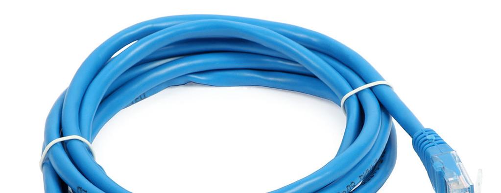
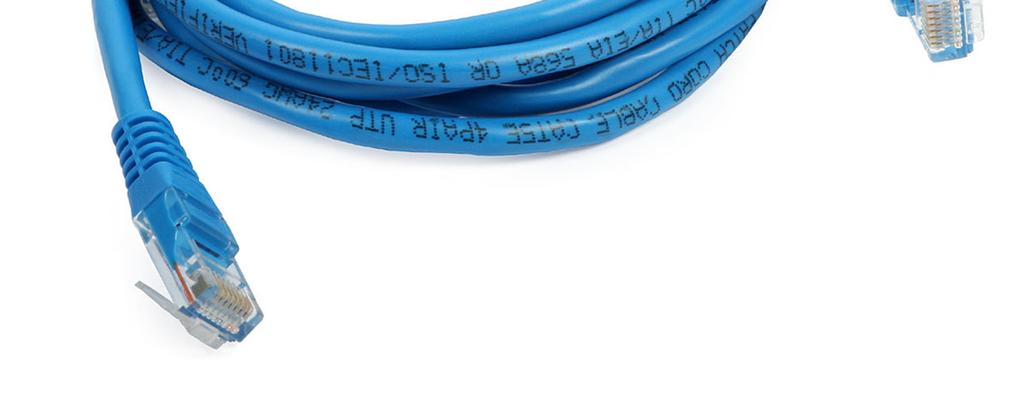
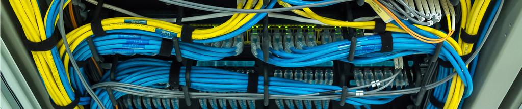
5 Twisted pair Consists of two metallic copper wires, twisted after a given step. Twisted pairs are of the following kinds: -STP (Shielded Twisted Pair), presenting protective shield for each pair and a global shield (metal braid) for whole cable; reduces interference but increased weight -FTP (Foiled Twisted Pair), or ScTP (Screened TP), providing an unique global shield -UTP (Unshielded Twisted Pair), being the non-shielded variant, only the separate pair insulation 11/27/2018 Vasile Dadarlat - Computer Networks 5
6 11/27/2018 Vasile Dadarlat - Computer Networks 6

7 11/27/2018 Vasile Dadarlat - Computer Networks 7

8 11/27/2018 Vasile Dadarlat - Computer Networks 8
 Problems: -susceptible to EM interference and noise -need for amplification (order of kilometers) -near end")
9 UTP: most common medium; used in: -Telephone network Between house and local exchange (subscriber loop) -Within a company s buildings To private branch exchange (PBX) -For local area networks (LAN) Ethernet at 10Mbps or 100Mbps Advantages: -cheap -easy to work with (to install on walls) Problems: -susceptible to EM interference and noise -need for amplification (order of kilometers) -near end crosstalk 11/27/2018 Vasile Dadarlat - Computer Networks 9
10 UTP Categories -Category 1 - Telecommunication, the cables for the analogue telephony -Category 2 (Low Speed Data), the cables for analogue and early digital telephony, offering data transmission services at low speeds -Category 3 (High Speed Data) defines cables used for LANs up to 10-16Mbps; the usual voice grade -Category 4 (Low Loss, High Performance Data) defines cables with higher performances, used at communication speeds of tens of Mbps (20Mbps) -Category 5 and 5e (Low Loss, Extended frequency, High Performance Data), are used in today s networks working at hundreds of Mbps; Commonly pre-installed in new office buildings. -Categories 6 and 7 (low attenuation and higher noise immunity) 11/27/2018 Vasile Dadarlat - Computer Networks 10
11 UTP Categories Standard Frequency Limit Data Speed CAT 2 1 MHz 4 Mbps CAT 3 16 MHz 10 Mbps CAT 5/5e 100 MHz 100/1000 Mbps CAT MHz 1 Gbps CAT MHz 10 Gbps CAT 7a 1000 MHZ 10 Gbps+ CAT 8 2 GHz 25/40 Gbps (30m)


12 11/27/2018 Vasile Dadarlat - Computer Networks 12
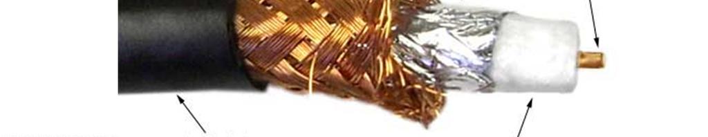
13 Coaxial cable Plastic coat Outer Insulator Inner (padding) conductor (braided shield) copper core Coax cable: -base-band cable, 50Ω impedance, used in Ethernet LANs -thick Ethernet (RG213), difficult to install -thin Ethernet (RG58), excellent versatility -broad-band cable, 75Ω impedance, used less for LANs, more for CATV or long distance telephone transmissions Advantages: goes up to 500MHz, repeaters every 1-2 km Drawback: is a shared broadcast medium, not for full duplex (switched) transmissions => will be replaced by UTP (LANs) or by fiber optics (long telephony trunks) 11/27/2018 Vasile Dadarlat - Computer Networks 13


14 11/27/2018 Vasile Dadarlat - Computer Networks 14
15 Fiber optic M Glass i e z core M a n t a Glass s t i c l a cladding In v e l iexternal s s t i c l a ( c l a d d i n g ) protective p r o t e c t o rcoat An inner glass core, covered by a glass cladding with different refractive and density proprieties; for protection and easier cabling colored plastic coat (see next slide also) Advantages: -low attenuation, fiber optic links with lengths in the order of ten of Kilometers -total immunity to electromagnetic field effects (carriers are the neutral photons) -transmission data rates in the order of Giga bps -easy for cabling, presenting low weight, small diameter (125/250µm) and being flexible 11/27/2018 Vasile Dadarlat - Computer Networks 15
16 250 µm 125 µm 9 µm Core diameter less than 10 microns Quality of fiber given by ratio between cladding diameter and whole fiber diameter n 2 n 1 Core Outer colored coat Cladding 11/27/2018 Vasile Dadarlat - Computer Networks 16

17 11/27/2018 Vasile Dadarlat - Computer Networks 17
18 Optical transmissions theoretical issues Optical transmissions governed by Snell s law: the critical angle for an ideal transmission is: θ c = arcsin(n 2 /n 1 ), n 1 and n 2 are the refractive indexes of the adjacent glass layers (core, respectively cladding); The lower refractive index of the cladding (with respect to the core) causes the light to be angled back into the core All attack angles for the light rays up to the critical angle will give minimum refraction and maximum of reflection => acceptance cone Ray outside the cone Refracted ray Acceptance cone 11/27/2018 Vasile Dadarlat - Computer Networks 18
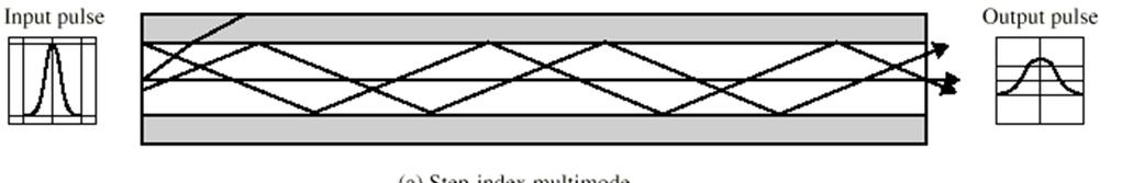
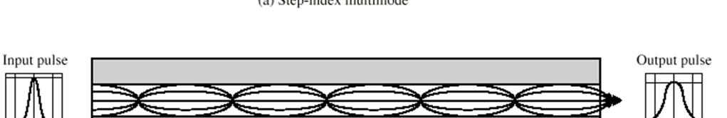
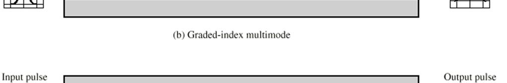
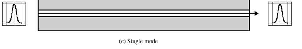
19 Light propagation modes: -step-index multimode, refraction index constant for the fibre core, doesn t matter distance to core s centre; implies different path lengths for light rays, making reception difficult; present a thicker core (hundreds of µm) => cheaper fiber -graded-index multimode, refraction index decreasing from the core centre to edges; offer a better focusing of the rays, so a lower attenuation and easier reception -single mode (mono-mode), the core diameter ~ light ray wavelength (5-8µm) => direct path for light ray, no loss, no attenuation, but more expensive Condition for monomode fiber: 2πa 2, c > 1 2 λ c - light ray wavelength; 2a fiber diameter; n 1 and n 2 are refractive indexes of the core, respectively cladding λ n - n 11/27/2018 Vasile Dadarlat - Computer Networks 19
20 Light propagation modes 11/27/2018 Vasile Dadarlat - Computer Networks 20
21 Transmission devices: -light emission using LEDs (light emitting diodes) or laser (diodes) (for single-mode transmissions) -reception of light and conversion into electrical signal using photodiodes For fibers: to be used wavelengths upper than the visible light ( > 750nm) Attenuation depends on the light ray wavelength => definition of 3 windows for the optical transmissions: -850nm centred window, used for multi-mode cheap transmissions; up to 150MHz signal frequency, attenuation of 3.5dB/km -1300nm centred window, used for graded-index multimode and single-mode transmissions; attenuation under 1dB/km, working frequencies: 0.5-1GHz -1550nm wavelength centred window, single-mode laser based transmissions, attenuation under 0.5dB/km, working frequencies up to 100GHz Use of fiber optic cables: -long haul trunks (10 100km without amplifiers) - used also for LANs or digital subscriber loops; usually as point-to-point links, shaped as ring or star 11/27/2018 Vasile Dadarlat - Computer Networks 21
22 Junctions Points where two fibers are connected to obtain a longer link or a fibre gets attached a terminal connector (permanent connection) Mechanical junction: fibers ends are cut, cleaned and polished, then aligned into a mechanical device Junction by fusion: fibers ends are heated-up close to melting point, than pasted and heated-down suddenly Junctions introduce extra attenuation (0.1 to 0.4 db) Connecting devices optical connectors: Non-permanent connections or variable configurations Usually prefabricated connectors, one side presenting a junction with fiber, the other connector side being free Connectors are: -passive, using taps with LED/Photodiode; do not affect cable transmission -active, using transformers from light/electric to electric/light signals and electric signal amplification Connectors introduce extra attenuation, higher than junctions (0.2 to 0.5 db) 11/27/2018 Vasile Dadarlat - Computer Networks 22
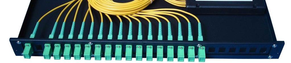


23 11/27/2018 Vasile Dadarlat - Computer Networks 23
24 Fiber Optic vs TP and Coax Information in this table, considering especially the costs, is relative and is subject to change; so it is pure informal and is accurate for year Attribute TP Coax FO Data rate per km n Mbps 100Mbps n Gbps Accessibility to be tapped Easy Easy Difficult Signal radiation Yes Yes no Grounding problems Yes Yes no Static problems Yes Yes No Sparkling Yes Yes no Bit error rate Size &Weight /data rate Medium Large small Cable cost per meter 50p 70p 70p Installing + maintenance costs N N 2N 11/27/2018 Vasile Dadarlat - Computer Networks 24
25 Soft-wire (wireless) media For unguided media: higher frequencies give higher transmission data rates Antenna based transmissions: -directional, antenna-to-antenna focused beam, requiring antennas alignment -omnidirectional, beam spread and may be received by many antennas LANs using wireless media present flexibility, easiness in installing and maintenance Main media: -terrestrial microwaves -satellite microwaves -broadcast radio waves -infrared rays Terrestrial microwaves Use frequency domain of 2-40GHz, offers up to 500MHz analog signal bandwidth, up to 100Mbps digital signal data rate Use of parabolic dish => line-of-sight transmissions of a focused electromagnetic beam => existence of a theoretical maximum distance between antennas: D = 7.14 sqr(k h), Where h is antenna s height and K an adjustment factor for waves reflection due to the earth curvature (a 4/3 value may be acceptable) For long hauls => a succession of relay towers 11/27/2018 Vasile Dadarlat - Computer Networks 25

26 Satellite microwave Transmissions (directional, station satellite station(s)): -optimum frequencies domain: 1-10GHz, due to low natural noise interferences (solar, wind, human devices); the most are point-to-point transmissions, referred as 4/6GHz band (the uplink based on 6GHz, the downlink frequencies centred on 4GHz. Today in use 12/14GHz (especially by small earth-stations) and 19/29GHz, offer higher bandwidth, but is need for overcoming attenuation problems. Satellite: a microwave relay station, receiving on one frequency band (uplink) and retransmits on another (downlink), avoiding interferences. These frequency channels transponders. Problem: satellite remains stationary with respect to the fixed (usually) earth-stations => equal rotation period as the earth s (launched for 35,784km height) Satellites on the same orbit, need for an angular displacement of 4 (4/6GHz band) and 3 (12/14GHz band) for no interferences between. Applications: -television distribution (Public Broadcasting Services programs broadcasted to stations and then to users, also Direct Broadcast Satellite video transmitted directly to user); today use of costless VSAT (Very Small Aperture Terminal) systems -long distance telephone transmissions -private networks (each using separate sub-channels) 11/27/2018 Vasile Dadarlat - Computer Networks 26
27 Broadcast Radio Being omni-directional transmission, radio antennas are not dish-shaped and may be mobile; generally radio waves use frequencies in the range of 3kHz 300GHz; broadcast radio (telecomms radio) covers VHF and part of UHF band: 30MHz 1GHz. Advantages: -good wave propagation, low reflection and refraction due to ionosphere -line-of-sight transmission obeys same law as terrestrial microwave; an usual value for radio repeaters: 20km Drawbacks: -multipath interference, due to reflections from land, water, natural and human-made objects. -radio transmissions allow up to 20Mhz analog signal bandwidth and up to 10Mbps digital signal data rate Infrared Infrared comms are based on modulated infrared light, using transceivers; use of THz frequency range; only line-of-sight transmissions => rigid station alignment or passive surface reflections => no interferences, due to impossibility to penetrate surfaces => good enough analog signals bandwidth or digital data rate (LANs at 16Mbps). No licences for use of infrared channels. 11/27/2018 Vasile Dadarlat - Computer Networks 27

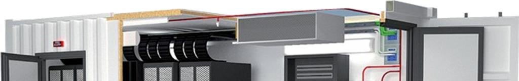
28 Elements of Structured Cabling A structured cabling system (SCS), featuring the open architecture, is a set of cabling and connectivity products that integrates the voice, data, video, and various management systems of a building. A BMS (Building Management System) consists of: -safety, life & fire alarms -security and access control (SAC) -energy systems (EMS) -heating, ventilation and air conditioning (HVAC) Usually were cabled separately and voice & data cabling isn t addressed during construction. Planning and installing the SCS from this phase => lower construction, labour and operational costs. With proper planning, it is not necessary to provide new cabling every time systems are changed or upgraded. (after International Engineers Consortium). 11/27/2018 Vasile Dadarlat - Computer Networks 28
 have created industry standards for cabling voice and")
 and are based on a structured")
29 The Electronic Industries Association/Telecommunications Industry Association (EIA/TIA) and International Standards Organization/ International Electrotechnical Commission (ISO/IEC) have created industry standards for cabling voice and data systems (EIA/TIA 568, 570, or ISO/IEC 11801). These standards address the cabling and cable-delivery methods (pathways and spaces) and are based on a structured subsystem architecture of cabling elements. 11/27/2018 Vasile Dadarlat - Computer Networks 29
30 11/27/2018 Vasile Dadarlat - Computer Networks 30
31 Sample case study: EIA/TIA 568A (Commercial Building Telecommunications Cabling Standard); applicable to campus, medium companies, etc. Used when designing a company LAN. The standard specifications concern: -the minimal requirements for cabling a building with a given number of offices - -the cabling topology and the allowed distances - -the components of the cabling system - -the transmission media and their characteristics - -the vertical cabling - -the horizontal cabling - -the cable identification manner - -the necessary documentation of the project. Are defined a number of subsystems: -building entrance facilities -equipment room -backbone cabling (vertical cabling) -telecommunication closet -horizontal cabling -work area s components 11/27/2018 Vasile Dadarlat - Computer Networks 31
32 Minimum Requirement -maximum linear covered distance of 3.000m -maximum surface of the cabling area of sqm. -maximum number of employees of minimum validity of the project of 10 years. Cabling Topology Topology: hierarchical star (star topology allows flexibility, the ring or bus topologies easy to be shaped as a star. Center of the star is the main cross connect (MC), designed for the whole cabled area. Second hierarchical level, the intermediate cross connect (IC), belongs usually to one building from the cabling area. The third level is the telecommunication closet (TC), associated to a floor from a building, or to a group of working rooms. 11/27/2018 Vasile Dadarlat - Computer Networks 32
33 Constitutive Cabling Components -main crossconnect (MC)-star center, a distribution center of main cables for other buildings or other cabling levels -intermediate crossconnect (IC)- local to each building, a one by floor distribution closet -telecommunication closet (TC) cabling toward workstations, more on a floor; contains the patch panels -intrabuilding backbone cabling between ICs and local TCs -interbuilding backbone cabling between MC and other buildings -equipment room, local to a cabling level; contains passive equipments (switching panels, cable ducts, measurement equip.), or active equip. like telephone central point, audio-video, LAN switches - interbuilding entrance facility, interface between outside cabling and inside backbone, especially grounding facilities -work area, identifies workstations, associated patch + drop cables, adapters -patch panels, switching panels for coax or UTP, or barrel panels for fiber optic -telecommunication outlets, connect workstations to the cabling system -cabling adapters, both passive or active 11/27/2018 Vasile Dadarlat - Computer Networks 33
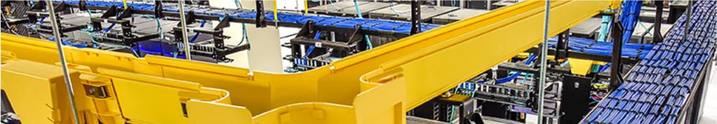
34 Horizontal cabling Telecomm closet TC Intermediate crossconnect IC Backbones Communication equipments Main crossconnect MC Inter-building links Entrance Facilities EF 11/27/2018 Vasile Dadarlat - Computer Networks 34
35 Transmission Media Media accepted: -coax cable of 50ohm, known as normal Ethernet cable (less used today) -multimode fiber optic with the 62,5/125 µm diameters -single-mode fiber at 8,3/125µm -twisted pair cables, either: Vertical Cabling -UTP (unshielded twisted pair) with an impedance of 100Ω -STP (shielded twisted pair) with impedance of 150Ω. Concerns inter & intra building backbones, specifying the maximum cable lengths, either directly from a TC to the MC, or using an IC 11/27/2018 Vasile Dadarlat - Computer Networks 35
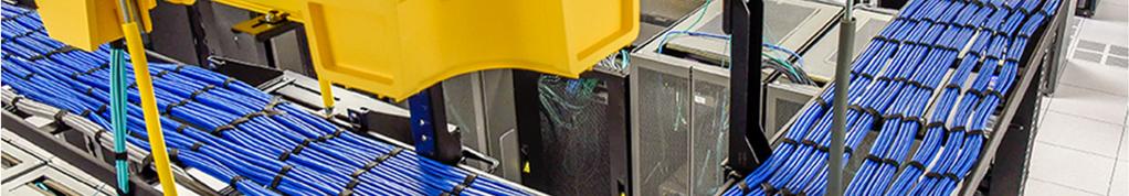
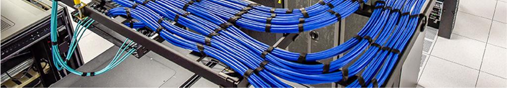
36 Horizontal Cabling Specifies connections (cables, their allowed maximum lengths, connectors) between the workstations and the local distribution closet (TC); the figure shows the drop cables from the workstation to outlet and the runs from outlets to local TC. Some types of used connectors: -RJ45 connector for 4-wire UTP cables -fiber optic connectors as ST and SC -BNC connectors for coax -hermaphrodite connector for STP outlets Installation Directives -cable installation (maximum admitted force/cable, mechanical manner of connecting the wires) -under-carpet horizontal cabling (distance between power and data lines, necessary shielding) -ground protection for the electric wires or the specific protection for the fiber optics 11/27/2018 Vasile Dadarlat - Computer Networks 36
37 Cable identification For each cable a label with an alphanumeric string, containing information about: - the area within the building where cable is located - the number of the floor where is located the local distribution closet - the numerical identifier of the workstation -the numerical identifier of the local distribution closet. Project Documentation Use of standard terminology and notations. Must include: -the logic drawing of the cabling system -the table for the vertical runs identification -the table for each local distribution closet, for a complete cable identification. 11/27/2018 Vasile Dadarlat - Computer Networks 37
38 Logic drawing of cabling Internal runs Center of the star cabling system External runs Toward other buildings 11/27/2018 Vasile Dadarlat - Computer Networks 38
39 11/27/2018 Vasile Dadarlat - Computer Networks 39
40 11/27/2018 Vasile Dadarlat - Computer Networks 40
41 11/27/2018 Vasile Dadarlat - Computer Networks 41
42 11/27/2018 Vasile Dadarlat - Computer Networks 42
William Stallings Data and Computer Communications. Bab 4 Media Transmisi
 William Stallings Data and Computer Communications Bab 4 Media Transmisi Overview Guided - wire Unguided - wireless Characteristics and quality determined by medium and signal For guided, the medium is
William Stallings Data and Computer Communications 7 th Edition. Chapter 4 Transmission Media
 William Stallings Data and Computer Communications 7 th Edition Chapter 4 Transmission Media Overview Guided - wire Unguided - wireless Characteristics and quality determined by medium and signal For guided,
DATA TRANSMISSION. ermtiong. ermtiong
 DATA TRANSMISSION Analog Transmission Analog signal transmitted without regard to content May be analog or digital data Attenuated over distance Use amplifiers to boost signal Also amplifies noise DATA
Chapter 4: Transmission Media
 Chapter 4: Transmission Media Page 1 Overview Guided - wire Unguided - wireless Characteristics and quality determined by medium and signal For guided, the medium is more important For unguided, the bandwidth
Data and Computer Communications Chapter 4 Transmission Media
 Data and Computer Communications Chapter 4 Transmission Media Ninth Edition by William Stallings Data and Computer Communications, Ninth Edition by William Stallings, (c) Pearson Education - Prentice Hall,
Module 2. Studoob.in - Where Learning is Entertainment
 Module 2 Module 2 Transmission media - Guided Transmission Media: Twisted pair, Coaxial cable, optical fiber, Wireless Transmission, Terrestrial microwave, Satellite microwave. Wireless Propagation: Ground
Transmission Media. - Bounded/Guided Media - Uubounded/Unguided Media. Bounded Media
 Transmission Media The means through which data is transformed from one place to another is called transmission or communication media. There are two categories of transmission media used in computer communications.
Transmission Media. Transmission Media 12/14/2016
 Transmission Media in data communications DDE University of Kashmir By Suhail Qadir System Analyst suhailmir@uok.edu.in Transmission Media the transmission medium is the physical path between transmitter
Computer Networks Lecture -4- Transmission Media. Dr. Methaq Talib
 Computer Networks Lecture -4- Transmission Media Dr. Methaq Talib Transmission Media A transmission medium can be broadly defined as anything that can carry information from a source to a destination.
Unguided Transmission Media
 CS311 Data Communication Unguided Transmission Media by Dr. Manas Khatua Assistant Professor Dept. of CSE IIT Jodhpur E-mail: manaskhatua@iitj.ac.in Web: http://home.iitj.ac.in/~manaskhatua http://manaskhatua.github.io/
Figure 4-1. Figure 4-2 Classes of Transmission Media
 Electromagnetic Spectrum Chapter 4 Transmission Media Computers and other telecommunication devices transmit signals in the form of electromagnetic energy, which can be in the form of electrical current,
Unguided Media and Matched Filter After this lecture, you will be able to Example?
 Unguided Media and Matched Filter After this lecture, you will be able to describe the physical and transmission characteristics of various unguided media Example? B.1 Unguided media Guided to unguided
Transmission Media. Beulah A L/CSE. 2 July 2008 Transmission Media Beulah A. 1
 Transmission Media Beulah A L/CSE 2 July 2008 Transmission Media Beulah A. 1 Guided Transmission Media Magnetic Media A tape can hold 7 gigabytes. A box can hold about 1000 tapes. Assume a box can be delivered
Overview. Chapter 4. Design Factors. Electromagnetic Spectrum
 Chapter 4 Transmission Media Overview Guided - wire Unguided - wireless Characteristics and quality determined by medium and signal For guided, the medium is more important For unguided, the bandwidth
Department Of Computer Science ASSAM UNIVERSITY, SILCHAR
 Department Of Computer Science ASSAM UNIVERSITY, SILCHAR Submitted By Submitted To: Mrinal Kanti Paul Mr. B.S. Mena 6 th Semester Roll No.: 03 Transmission Media: Sender Physical Layer Physical Layer Receiver
Data and Computer Communications. Tenth Edition by William Stallings
 Data and Computer Communications Tenth Edition by William Stallings Data and Computer Communications, Tenth Edition by William Stallings, (c) Pearson Education - Prentice Hall, 2013 Wireless Transmission
Transmission Medium/ Media
 Transmission Medium/ Media The successful transmission of data depends principally on two factors: the quality of the signal being transmitted and the characteristics of the transmission medium Transmission
Class 4 ((Communication and Computer Networks))
)") Class 4 ((Communication and Computer Networks)) Lesson 3... Transmission Media, Part 1 Abstract The successful transmission of data depends principally on two factors: the quality of the signal being transmitted
Class 4 ((Communication and Computer Networks)) Lesson 3... Transmission Media, Part 1 Abstract The successful transmission of data depends principally on two factors: the quality of the signal being transmitted
Maximum date rate=2hlog 2 V bits/sec. Maximum number of bits/sec=hlog 2 (1+S/N)
") Basics Data can be analog or digital. The term analog data refers to information that is continuous, digital data refers to information that has discrete states. Analog data take on continuous values.
Basics Data can be analog or digital. The term analog data refers to information that is continuous, digital data refers to information that has discrete states. Analog data take on continuous values.
LE/EECS 3213 Fall Sebastian Magierowski York University. EECS 3213, F14 L8: Physical Media
 LE/EECS 3213 Fall 2014 L8: Physical Media Properties Sebastian Magierowski York University 1 Key characteristics of physical media What signals in media are made out of Delay through media Attenuation
Books: 1. Data communications by William L Schweber 2. Data communication and Networking by Behrouz A F0rouzan
 Books: 1. Data communications by William L Schweber 2. Data communication and Networking by Behrouz A F0rouzan Twisted Pair cable Multiconductor flat cable Advantages of Twisted Pair Cable Simplest to
Contents. ITS323: Introduction to Data Communications CSS331: Fundamentals of Data Communications. Transmission Media and Spectrum.
 2 ITS323: Introduction to Data Communications CSS331: Fundamentals of Data Communications Sirindhorn International Institute of Technology Thammasat University Prepared by Steven Gordon on 3 August 2015
ITS323: Introduction to Data Communications CSS331: Fundamentals of Data Communications
 ITS323: Introduction to Data Communications CSS331: Fundamentals of Data Communications Sirindhorn International Institute of Technology Thammasat University Prepared by Steven Gordon on 3 August 2015
CS311 -Data Communication Unguided Transmission Media
 CS311 -Data Communication Unguided Transmission Media Dr. Manas Khatua Assistant Professor Dept. of CSE IIT Jodhpur E-mail: manaskhatua@iitj.ac.in INTRODUCTION -Physical Path between transmitter and receiver
Data and Computer Communications
 Data and Computer Communications Chapter 4 Transmission Media Dr. Bhargavi Goswami, HOD CS, Associate Professor, Garden City College, Bangalore. Transmission Media Communication channels in the animal
Chapter 4: Practical Communication Systems. 18/09/2016 Nurul/DEE 3413/Practical Com System 1
 Chapter 4: Practical Communication Systems 18/09/2016 Nurul/DEE 3413/Practical Com System 1 Outline Fibre Optic Communication System Telephone System Radio Communication System Satellite Communication
Introduction to LAN/WAN. Physical Layer
 Introduction to LAN/WAN Physical Layer Topics Introduction Theory Transmission Media Purpose of Physical Layer Transport bits between machines How do we send 0's and 1's across a medium? Ans: vary physical
is a method of transmitting information from one place to another by sending light through an optical fiber. The light forms an electromagnetic
 is a method of transmitting information from one place to another by sending light through an optical fiber. The light forms an electromagnetic carrier wave that is modulated to carry information. The
TRANSMISSION MEDIA CHAPTER Guided Transmission Media. 4.2 Wireless Transmission. 4.3 Wireless Propagation. 4.4 Line-of-Sight Transmission
 TRANSMISSION MEDIA CHAPTER4 4.1 Guided Transmission Media 4.2 Wireless Transmission 4.3 Wireless Propagation 4.4 Line-of-Sight Transmission 4.5 Recommended Reading and Web Sites 4.6 Key Terms, Review Questions,
Chapter 2: Computer Networks
 Chapter 2: Computer Networks 2.1: Physical Layer: representation of digital signals 2.2: Data Link Layer: error protection and access control 2.3: Network infrastructure 2.4 2.5: Local Area Network examples
In this section of my blog, I will be discussing different transmission methods and why those particular methods are used in particular situations:
 In this section of my blog, I will be discussing different transmission methods and why those particular methods are used in particular situations: Transmission Methods are a variety of different methods
Media. Twisted pair db/km at 1MHz 2 km. Coaxial cable 7 db/km at 10 MHz 1 9 km. Optical fibre 0.2 db/km 100 km
 Media Attenuation Repeater spacing Twisted pair 10-12 db/km at 1MHz 2 km Coaxial cable 7 db/km at 10 MHz 1 9 km Optical fibre 0.2 db/km 100 km conniq.com provides an excellent tutorial on physical media.
Industrial Automation
 OPTICAL FIBER. SINGLEMODE OR MULTIMODE It is important to understand the differences between singlemode and multimode fiber optics before selecting one or the other at the start of a project. Its different
Jaringan Komputer. Outline. The Physical Layer
 Jaringan Komputer The Physical Layer Outline Defines the mechanical, electrical, and timing interfaces to the network Theoretical analysis of data transmission Kinds of transmission media Examples: the
Data Communication & Networking CSCI Dr. Thomas Hicks Computer Science Department Trinity University 1
 Data Communication & Networking CSCI 3342 Dr. Thomas Hicks Computer Science Department Trinity University 1 1 Must Consider Protocols 2 Protocols http://www.networksorcery.com/enp/protocol.htm http://www.networksorcery.com/enp/topic/ipsuite.htm
Introduction to Fiber Optics
 Introduction to Fiber Optics Dr. Anurag Srivastava Atal Bihari Vajpayee Indian Institute of Information Technology and Manegement, Gwalior Milestones in Electrical Communication 1838 Samuel F.B. Morse
Data Communication Prof. Ajit Pal Department of Computer Science & Engineering Indian Institute of Technology, Kharagpur Lecture No # 6 Unguided Media
 Data Communication Prof. Ajit Pal Department of Computer Science & Engineering Indian Institute of Technology, Kharagpur Lecture No # 6 Unguided Media Hello and welcome to today s lecture on unguided media.
Copper and Fiber Optic Cables
 Copper and Fiber Optic Cables Pietro Nicoletti piero[at]studioreti.it Cables-Engl - 1 P. Nicoletti: see note pag. 2 Copyright note These slides are protected by copyright and international treaties. The
Why Using Fiber for transmission
 Why Using Fiber for transmission Why Using Fiber for transmission Optical fibers are widely used in fiber-optic communications, where they permit transmission over long distances and at very high bandwidths.
Point-to-Point Communications
 Point-to-Point Communications Key Aspects of Communication Voice Mail Tones Alphabet Signals Air Paper Media Language English/Hindi English/Hindi Outline of Point-to-Point Communication 1. Signals basic
COM 46: ADVANCED COMMUNICATIONS jfm 07 FIBER OPTICS
 FIBER OPTICS Fiber optics is a unique transmission medium. It has some unique advantages over conventional communication media, such as copper wire, microwave or coaxial cables. The major advantage is
Lecture 3: Transmission Media
 Lecture 3: Transmission Media Dr. Mohd Nazri Bin Mohd Warip High Performance Broadband Networks Research Group Embedded, Networks and Advanced Computing Research Cluster School of Computer and Communication
Chapter 2. Physical Layer
 Chapter 2 Physical Layer Lecture 1 Outline 2.1 Analog and Digital 2.2 Transmission Media 2.3 Digital Modulation and Multiplexing 2.4 Transmission Impairment 2.5 Data-rate Limits 2.6 Performance Physical
Local Networks. Lecture 2 23-Mar-2016
 Local Networks Lecture 2 23-Mar-2016 Roadmap of the course Last time LAN and networking introduction Models for data communication Data transmission issues Today Transmission media Error detection methods
COMMUNICATION SYSTEMS -I
 COMMUNICATION SYSTEMS -I Communication : It is the act of transmission of information. ELEMENTS OF A COMMUNICATION SYSTEM TRANSMITTER MEDIUM/CHANNEL: The physical medium that connects transmitter to receiver
Lectureo5 FIBRE OPTICS. Unit-03
 Lectureo5 FIBRE OPTICS Unit-03 INTRODUCTION FUNDAMENTAL IDEAS ABOUT OPTICAL FIBRE Multimode Fibres Multimode Step Index Fibres Multimode Graded Index Fibres INTRODUCTION In communication systems, there
Lecture 5 Transmission. Physical and Datalink Layers: 3 Lectures
 Lecture 5 Transmission Peter Steenkiste School of Computer Science Department of Electrical and Computer Engineering Carnegie Mellon University 15-441 Networking, Spring 2004 http://www.cs.cmu.edu/~prs/15-441
Computer Networks
 15-441 Computer Networks Physical Layer Professor Hui Zhang hzhang@cs.cmu.edu 1 Communication & Physical Medium There were communications before computers There were communication networks before computer
- Characteristic impedance of cabling links is characterised by Return Loss
 ISO/IEC 11801 ISO 11801 is the principle design standard for structured cabling systems for all countries of the world that do not have more specific standards, such as ISO 11801 (European Union), TIA
Chapter 1 Introduction
 Wireless Information Transmission System Lab. Chapter 1 Introduction National Sun Yat-sen University Table of Contents Elements of a Digital Communication System Communication Channels and Their Wire-line
C05a: Transmission Media
 CISC 7332X T6 C05a: Transmission Media Hui Chen Department of Computer & Information Science CUNY Brooklyn College 9/25/2018 CUNY Brooklyn College 1 Review Discussed Overview and network applications Application
Bluetooth BlueTooth - Allows users to make wireless connections between various communication devices such as mobile phones, desktop and notebook comp
 ECE 271 Week 8 Bluetooth BlueTooth - Allows users to make wireless connections between various communication devices such as mobile phones, desktop and notebook computers - Uses radio transmission - Point-to-multipoint
Fiber Optic Principles. Oct-09 1
 Fiber Optic Principles Oct-09 1 Fiber Optic Basics Optical fiber Active components Attenuation Power budget Bandwidth Oct-09 2 Reference www.flukenetworks.com/fiber Handbook Fiber Optic Technologies (Vivec
CHAPTER -15. Communication Systems
 CHAPTER -15 Communication Systems COMMUNICATION Communication is the act of transmission and reception of information. COMMUNICATION SYSTEM: A system comprises of transmitter, communication channel and
COMP211 Physical Layer
 COMP211 Physical Layer Data and Computer Communications 7th edition William Stallings Prentice Hall 2004 Computer Networks 5th edition Andrew S.Tanenbaum, David J.Wetherall Pearson 2011 Material adapted
Optical Fiber. n 2. n 1. θ 2. θ 1. Critical Angle According to Snell s Law
 ECE 271 Week 10 Critical Angle According to Snell s Law n 1 sin θ 1 = n 1 sin θ 2 θ 1 and θ 2 are angle of incidences The angle of incidence is measured with respect to the normal at the refractive boundary
Last Time. Transferring Information. Today (& Tomorrow (& Tmrw)) Application Layer Example Protocols ftp http Performance.
) Application Layer Example Protocols ftp http Performance.") 15-441 Lecture 5 Last Time Physical Layer & Link Layer Basics Copyright Seth Goldstein, 2008 Application Layer Example Protocols ftp http Performance Application Presentation Session Transport Network
15-441 Lecture 5 Last Time Physical Layer & Link Layer Basics Copyright Seth Goldstein, 2008 Application Layer Example Protocols ftp http Performance Application Presentation Session Transport Network
ECE 435 Network Engineering Lecture 16
 ECE 435 Network Engineering Lecture 16 Vince Weaver http://web.eece.maine.edu/~vweaver vincent.weaver@maine.edu 1 November 2018 Announcements No homework this week. Demo of infiniband / fiber / ethernet
2. The Basic principle of optical fibre (Or) Working principle of optical fibre (or) Total internal reflection
 Working principle of optical fibre (or) Total internal reflection") Introduction Fibre optics deals with the light propagation through thin glass fibres. Fibre optics plays an important role in the field of communication to transmit voice, television and digital data signals
Introduction Fibre optics deals with the light propagation through thin glass fibres. Fibre optics plays an important role in the field of communication to transmit voice, television and digital data signals
TECHNICAL ARTICLE: DESIGN BRIEF FOR INDUSTRIAL FIBRE OPTICAL NETWORKS
 TECHNICAL ARTICLE: DESIGN BRIEF FOR INDUSTRIAL FIBRE OPTICAL NETWORKS Designing and implementing a fibre optical based communication network intended to replace or augment an existing communication network
CHAPTER ONE INTRODUCTION
 CHAPTER ONE INTRODUCTION 1.1 Background A communication system transmits information from one place to another, whether separated by a few kilometers or by transoceanic distances. Information is often
ECE 435 Network Engineering Lecture 20
 ECE 435 Network Engineering Lecture 20 Vince Weaver http://web.eece.maine.edu/~vweaver vincent.weaver@maine.edu 16 November 2017 Announcements SC 17 takeaway Lots of network stuff there, the network being
Lecture 5 Transmission
 Lecture 5 Transmission David Andersen Department of Computer Science Carnegie Mellon University 15-441 Networking, Spring 2005 http://www.cs.cmu.edu/~srini/15-441/s05 1 Physical and Datalink Layers: 3
Chapter 2 Transmission Media and Propagation Mechanisms
 Chapter 2 Transmission Media and Propagation Mechanisms 2.1 Introduction Signals generated by the source need to be transported to the destination over a communication s channel. A communication channel
Objectives of transmission lines
 Introduction to Transmission Lines Applications Telephone Cable TV (CATV, or Community Antenna Television) Broadband network High frequency (RF) circuits, e.g., circuit board, RF circuits, etc. Microwave
Physical Layer Cabling: Fiber-Optic
 Physical Layer Cabling: Fiber-Optic Fiber-Optic Basics The EM Spectrum: Physics and Math Attenuation and Dispersion in Fiber Fiber-Optic Hardware Networking over Fiber-Optic Safety with Fiber Fiber-Optic
Chapter 3 Digital Transmission Fundamentals
 Chapter 3 Digital Transmission Fundamentals Line Coding What is Line Coding? Mapping of binary information sequence into the digital signal that enters the channel Ex. 1 maps to +A square pulse; 0 to A
Optical Fiber Communication
 A Seminar report On Optical Fiber Communication Submitted in partial fulfillment of the requirement for the award of degree Of Mechanical SUBMITTED TO: www.studymafia.org SUBMITTED BY: www.studymafia.org
Technician License Course Chapter 4. Lesson Plan Module 9 Antenna Fundamentals, Feed Lines & SWR
 Technician License Course Chapter 4 Lesson Plan Module 9 Antenna Fundamentals, Feed Lines & SWR The Antenna System Antenna: Transforms current into radio waves (transmit) and vice versa (receive). Feed
WHITE PAPER LINK LOSS BUDGET ANALYSIS TAP APPLICATION NOTE LINK LOSS BUDGET ANALYSIS
 TAP APPLICATION NOTE LINK LOSS BUDGET ANALYSIS WHITE PAPER JULY 2017 1 Table of Contents Basic Information... 3 Link Loss Budget Analysis... 3 Singlemode vs. Multimode... 3 Dispersion vs. Attenuation...
A presentation of Pirmin Vogel, Benjamin Weber and Marco Karch 2008 by P.V.B.M.M.K. Ltd. & Co KG (release date , ver. 1.
 A presentation of Pirmin Vogel, Benjamin Weber and Marco Karch 2008 by P.V.B.M.M.K. Ltd. & Co KG (release date 07 04 08, ver. 1.02) introduction Cablecom canceled many TV channels out of the program to
CPSC Network Programming. How do computers really communicate?
 CPSC 360 - Network Programming Data Transmission Michele Weigle Department of Computer Science Clemson University mweigle@cs.clemson.edu February 11, 2005 http://www.cs.clemson.edu/~mweigle/courses/cpsc360
Chapter 18: Fiber Optic and Laser Technology
 Chapter 18: Fiber Optic and Laser Technology Chapter 18 Objectives At the conclusion of this chapter, the reader will be able to: Describe the construction of fiber optic cable. Describe the propagation
Physical Layer. Networked Systems 3 Lecture 5
 Physical Layer Networked Systems 3 Lecture 5 Lecture Outline Physical layer concepts Wired links Unshielded twisted pair, coaxial cable, optical fibre Encoding data onto a wire Wireless links Carrier modulation
Technician Licensing Class T9
 Technician Licensing Class T9 Amateur Radio Course Monroe EMS Building Monroe, Utah January 11/18, 2014 January 22, 2014 Testing Session Valid dates: July 1, 2010 June 30, 2014 Amateur Radio Technician
CSE 561 Bits and Links. David Wetherall
 CSE 561 Bits and Links David Wetherall djw@cs.washington.edu Topic How do we send a message across a wire? The physical/link layers: 1. Different kinds of media 2. Encoding bits 3. Model of a link Application
Telecommunication Wiring Questions
 Telecommunication Wiring Questions 1. is the process of modifying a carrier frequency in rhythm to the audio frequency. A, Modulation B. Amplitude C. Change of phase D. Interference 2. is the property
Physical Layer. Networked Systems Architecture 3 Lecture 6
 Physical Layer Networked Systems Architecture 3 Lecture 6 Lecture Outline Physical layer concepts Wired links Unshielded twisted pair, coaxial cable, optical fibre Encoding data onto a wire Wireless links
Antennas and Propagation. Chapter 5
 Antennas and Propagation Chapter 5 Introduction An antenna is an electrical conductor or system of conductors Transmission - radiates electromagnetic energy into space Reception - collects electromagnetic
Data and Computer Communications Chapter 3 Data Transmission
 Data and Computer Communications Chapter 3 Data Transmission Eighth Edition by William Stallings Transmission Terminology data transmission occurs between a transmitter & receiver via some medium guided
ITL Basics of Encoding and Wiring
 ITL Basics of Encoding and Wiring Objectives Quick overview of wide-area communications Define the term Structured Wiring Define "analog" and "digital" data. List the common methods used to encode analog/digital
Introduction to Telecommunications and Computer Engineering Unit 3: Communications Systems & Signals
 Introduction to Telecommunications and Computer Engineering Unit 3: Communications Systems & Signals Syedur Rahman Lecturer, CSE Department North South University syedur.rahman@wolfson.oxon.org Acknowledgements
Optical Communications and Networks - Review and Evolution (OPTI 500) Massoud Karbassian
 Massoud Karbassian") Optical Communications and Networks - Review and Evolution (OPTI 500) Massoud Karbassian m.karbassian@arizona.edu Contents Optical Communications: Review Optical Communications and Photonics Why Photonics?
Optical Communications and Networks - Review and Evolution (OPTI 500) Massoud Karbassian m.karbassian@arizona.edu Contents Optical Communications: Review Optical Communications and Photonics Why Photonics?
Vehicle Networks. Wireless communication basics. Univ.-Prof. Dr. Thomas Strang, Dipl.-Inform. Matthias Röckl
 Vehicle Networks Wireless communication basics Univ.-Prof. Dr. Thomas Strang, Dipl.-Inform. Matthias Röckl Outline Wireless Signal Propagation Electro-magnetic waves Signal impairments Attenuation Distortion
E-716-A Mobile Communications Systems. Lecture #2 Basic Concepts of Wireless Transmission (p1) Instructor: Dr. Ahmad El-Banna
 Instructor: Dr. Ahmad El-Banna") October 2014 Ahmad El-Banna Integrated Technical Education Cluster At AlAmeeria E-716-A Mobile Communications Systems Lecture #2 Basic Concepts of Wireless Transmission (p1) Instructor: Dr. Ahmad El-Banna
October 2014 Ahmad El-Banna Integrated Technical Education Cluster At AlAmeeria E-716-A Mobile Communications Systems Lecture #2 Basic Concepts of Wireless Transmission (p1) Instructor: Dr. Ahmad El-Banna
Antennas and Propagation. Chapter 5
 Antennas and Propagation Chapter 5 Introduction An antenna is an electrical conductor or system of conductors Transmission - radiates electromagnetic energy into space Reception - collects electromagnetic
Antennas & Propagation. CSG 250 Fall 2007 Rajmohan Rajaraman
 Antennas & Propagation CSG 250 Fall 2007 Rajmohan Rajaraman Introduction An antenna is an electrical conductor or system of conductors o Transmission - radiates electromagnetic energy into space o Reception
Practical Antennas and. Tuesday, March 4, 14
 Practical Antennas and Transmission Lines Goals Antennas are the interface between guided waves (from a cable) and unguided waves (in space). To understand the various properties of antennas, so as to
DDPP 2163 Propagation Systems. Satellite Communication
 DDPP 2163 Propagation Systems Satellite Communication 1 Satellite Two far apart stations can use a satellite as a relay station for their communication It is possible because the earth is a sphere. Radio
Computer Networks and ITCP/IP Protocols 1
 Computer Networks and ITCP/IP Protocols 1 Module 11 Wired and wireless physical layers Introduction In this module, we will look at wired and wireless physical layer components. We will begin with different
Chapter-15. Communication systems -1 mark Questions
 Chapter-15 Communication systems -1 mark Questions 1) What are the three main units of a Communication System? 2) What is meant by Bandwidth of transmission? 3) What is a transducer? Give an example. 4)
Data Communication. Chapter 3 Data Transmission
 Data Communication Chapter 3 Data Transmission ١ Terminology (1) Transmitter Receiver Medium Guided medium e.g. twisted pair, coaxial cable, optical fiber Unguided medium e.g. air, water, vacuum ٢ Terminology
Guided Propagation Along the Optical Fiber. Xavier Fernando Ryerson Comm. Lab
 Guided Propagation Along the Optical Fiber Xavier Fernando Ryerson Comm. Lab The Nature of Light Quantum Theory Light consists of small particles (photons) Wave Theory Light travels as a transverse electromagnetic
COPPER + LWL RAW CABLES
 COPPER + LWL RAW Twisted Pair Cables... 112 TV/SAT Cables... 116 Fiber Optic Raw Cables... 120 DIGITUS CAT 7 twisted pair installation cable 4x2xAWG23 S-FTP CAT 7 1000 MHz LSZH installation cable For installation
AESA TECHNOLOGY OF LAN CABLE
 TECHNOLOGY OF LAN CABLE CONTENT CHAPTER INTRODUCTION CHAPTER LOCAL AREA NETWORK (LAN) CHAPTER STRUCTURED CABLING SYSTEM (SCS) CHAPTER OPTICAL FIBER CABLE CHAPTER STANDARD CHAPTER COPPER LAN CABLE DESIGN
ECE 271 INTRODUCTION TO TELECOMMUNICATION NETWORKS HOMEWORK QUESTIONS ECE 271 HOMEWORK-1
 ECE 271 INTRODUCTION TO TELECOMMUNICATION NETWORKS HOMEWORK QUESTIONS Homework Question 1 ECE 271 HOMEWORK-1 Allocated channel bandwidth for commercial TV is 6 MHz. a. Find the maximum number of analog
EE 304 TELECOMMUNICATIONs ESSENTIALS HOMEWORK QUESTIONS AND ANSWERS
 Homework Question 1 EE 304 TELECOMMUNICATIONs ESSENTIALS HOMEWORK QUESTIONS AND ANSWERS Allocated channel bandwidth for commercial TV is 6 MHz. a. Find the maximum number of analog voice channels that
Computer Networks 1 (Mạng Máy Tính 1) Lectured by: Nguyễn Đức Thái
 Lectured by: Nguyễn Đức Thái") Computer Networks 1 (Mạng Máy Tính 1) Lectured by: Nguyễn Đức Thái Lecture 2: Communication Media Reference: Chapter 2 - Computer Networks, Andrew S. Tanenbaum, 4th Edition, Prentice Hall, 2003. Content
Computer Networks 1 (Mạng Máy Tính 1) Lectured by: Nguyễn Đức Thái Lecture 2: Communication Media Reference: Chapter 2 - Computer Networks, Andrew S. Tanenbaum, 4th Edition, Prentice Hall, 2003. Content
Fiber Optic Communications Communication Systems
 INTRODUCTION TO FIBER-OPTIC COMMUNICATIONS A fiber-optic system is similar to the copper wire system in many respects. The difference is that fiber-optics use light pulses to transmit information down
Metallic Transmission Lines
 METALLIC CABLE TRANSMISSION MEDIA : Metallic Transmission Lines, Transverse Electromagnetic Waves, Characteristics of Electromagnetic Waves, Transmission Line Classifications, Metallic Transmission Line