A presentation of Pirmin Vogel, Benjamin Weber and Marco Karch 2008 by P.V.B.M.M.K. Ltd. & Co KG (release date , ver. 1.
|
|
|
- Gerard Barker
- 6 years ago
- Views:
Transcription
1 A presentation of Pirmin Vogel, Benjamin Weber and Marco Karch 2008 by P.V.B.M.M.K. Ltd. & Co KG (release date , ver. 1.02)


2 introduction Cablecom canceled many TV channels out of the program to get the needed bandwidth for digital TV now a new technology is needed to provide higher bandwidth ti l fib! optical fibers! but what the hell is that?!?
3 basic principle total reflectance which means look at the eqations for Gamma: parallel polarization vertical polarization


4 Snellius s refraction law with refraction indexes:


5 structure of a single fiber core glass, n=1.48 cladding glass, n=1.46 buffer some kind of resin jacket plastic
6 dispersion if the entering angle is near the ray gets reflected more often than a ray with a higher entering angle propagation delay
7 dispersion If an impulse consisting of several rays with different angles enters the fiber some rays are reflected more often than others an therefore need more time to pass the fiber. the impulse gets streched dispersion limits the transfer rate!
8 different modes light of highmode: small angle, often reflected light of low mode: high angle, less often reflected, travels almost parallel to the axis of the fiber
9 multimode step index fiber constant refractive indexes of core and cladding a lot of different modes high dispersion only for short distances used
10 multimode graded index fiber refractive index of core gets smaller as radius increases, therefore the light rays bend smoothly as they approach the cladding the resulting paths reduce the dispersion because light with a high g p p g g mode (high angle) passes more through regions of small index than those of small mode
11 monomode / singlemode fiber very small core diameter rays pass the fiber almost parallel to the axis of the fiber only light of one wavelength is transmitted onlyweak dispersion very long ranges and transfer rates possible
12 comparison
13 bandwidth length product characterstical quantity typical values: multimode step index: 100 MHz * km mulitmode graded index: 1 GHz * km Monomode/singlemode: 10 GHz * km Gigabit ethernet (1000Base T): maximum length = 100m, bandwidth = 62.5 MHz
14 comparison to copper cables + very high transfer bandwidth + small damping even at long ranges + external electromagnetic fields do not affect the transmission + high termic and chemical stability + almostunlimited resources (glass sand) + less material for shielding, optic fiber cables are much lighter than copper cables expensive installation and equipment low cost effectiveness at close range
15 additions light source: LED oder laser) damping due to splices: multimode step index: 5 6dB/km at 850nm mulitmode graded index: db/km at 850nm Monomode/singlemode: 0.36 db/km at 1310nm different wavelenghts: 850nm, 1310nm or 1550nm
16 different DVB s DVB S (satellite) DVB T (terrestrial television) DVB C (cable) DVB H (handhelds)
17 about DVB s same frequencies as analogue TV bandwidth: 7 MHz VHF (47 68 and MHz) 8 Mhz UHF ( MHz) bandwidth is used more efficiently through COFDM (Coded Orthogonal Frequency Division Multiplex) each subcarrier is modulated with QAM
18 about DVB s data rate Mbits/s 4 programs per channel Mbits/s per program PAL (3 5 Mbits/s) DVD 9.8 Mbits/s encoded in DVB MPEG contains MPEG 2 streams redundant information
19 FEC (Forward Error Correction)
20 FEC (Forward Error Correction)
21 QAM (Quadrature Amplitude Modulation) sender receiver low pass filter multiplication
22 QAM (Quadrature Amplitude Modulation) sender
23 QAM (Quadrature Amplitude Modulation) receiver
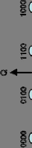


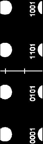
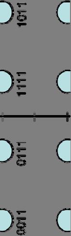
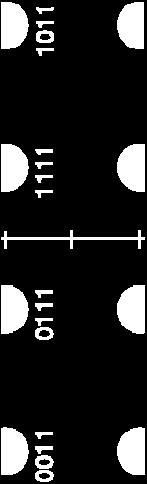
24 QAM (Quadrature Amplitude Modulation)
25 Uetliberg Specifications 16 QAM 1/16 guard 8 MHz channel splits into 6817 subcarriers distance between subcarriers: khz Mbits/s 5/6 code rate sampling rate MHz
26 Advatages multitude of programs low transmitting power diversity reception (synchronisation, guard) coverage recording low costs
27 Disadvatages interference prone video quality fast moving receivers (subcarriers overlap) transmission delay

28
29 dipole antennas first developed 1886 by H. Herz for transmitting or receiving radio frequency energy those antennas are theoretically the most simplest ones


30 technical specification (half wave antenna) folded dipole λ/2 typical LC oscillator elongated dipole λ/2 only difference is only difference is the impedance (300 Ohm 75 Ohm)
31 technical specification (half wave antenna) λ/2 dipole (75 Ohm) λ/4 λ/4 feed line formed dby two quarter wavelength conductors or elements transforms high frequency AC into electromagnetic waves
32 technical specification (half wave antenna) AC voltage anti nodes nodes at the ends λ/2 dipole (75 Ohm) energized with UHF AC (several GHz) U I phase shift AC current nodes at the ends at the ends


33 emission diagrams electricand magnetic UHF field the resulting emission i diagram of a of a λ/2 dipole λ/2 dipole is a slightly flattened torus


34 general emission diagram the length of a dipole can be varied in its resonant load most common is the λ/2 dipole other wave length antenna designs exist (L= λ, 2 λ, ) due to the used length the radiation emission varies in different directional radio patterns
 (reference radiator with which other sources are compared G")
35 antenna gain G (antenna gain) is the ratio of surface power radiated by the antenna to the surface power radiated by a hypothetical isotropic antenna isotropic radiator: theoretical point source of waves which exhibits the same magnitude (measuring in all directions) (reference radiator with which other sources are compared G = 0 dbi )
36 antenna gain calculation of the gain of a λ/2 dipole Gain of dipole antennas length L in λ Gain Gain(dB) << dB dB dB dB dB dB dB dB
 the")
] or 2.15 dbi.")
37 antenna gain gain of a half wave dipole (same as left), the scale is in dbi (decibels over isotropic) the maximum theoretical gain of a λ/2 dipole is [10*log (1.64)] or 2.15 dbi.) maximum radiation gain follows this direction
William Stallings Data and Computer Communications 7 th Edition. Chapter 4 Transmission Media
 William Stallings Data and Computer Communications 7 th Edition Chapter 4 Transmission Media Overview Guided - wire Unguided - wireless Characteristics and quality determined by medium and signal For guided,
CHAPTER 8 ANTENNAS 1
 CHAPTER 8 ANTENNAS 1 2 Antennas A good antenna works A bad antenna is a waste of time & money Antenna systems can be very inexpensive and simple They can also be very expensive 3 Antenna Considerations
Data and Computer Communications Chapter 4 Transmission Media
 Data and Computer Communications Chapter 4 Transmission Media Ninth Edition by William Stallings Data and Computer Communications, Ninth Edition by William Stallings, (c) Pearson Education - Prentice Hall,
Industrial Automation
 OPTICAL FIBER. SINGLEMODE OR MULTIMODE It is important to understand the differences between singlemode and multimode fiber optics before selecting one or the other at the start of a project. Its different
Half-Wave Dipole. Radiation Resistance. Antenna Efficiency
 Antennas Simple Antennas Isotropic radiator is the simplest antenna mathematically Radiates all the power supplied to it, equally in all directions Theoretical only, can t be built Useful as a reference:
Class 4 ((Communication and Computer Networks))
)") Class 4 ((Communication and Computer Networks)) Lesson 3... Transmission Media, Part 1 Abstract The successful transmission of data depends principally on two factors: the quality of the signal being transmitted
Class 4 ((Communication and Computer Networks)) Lesson 3... Transmission Media, Part 1 Abstract The successful transmission of data depends principally on two factors: the quality of the signal being transmitted
Figure 4-1. Figure 4-2 Classes of Transmission Media
 Electromagnetic Spectrum Chapter 4 Transmission Media Computers and other telecommunication devices transmit signals in the form of electromagnetic energy, which can be in the form of electrical current,
Module 2. Studoob.in - Where Learning is Entertainment
 Module 2 Module 2 Transmission media - Guided Transmission Media: Twisted pair, Coaxial cable, optical fiber, Wireless Transmission, Terrestrial microwave, Satellite microwave. Wireless Propagation: Ground
Transmission Media. Transmission Media 12/14/2016
 Transmission Media in data communications DDE University of Kashmir By Suhail Qadir System Analyst suhailmir@uok.edu.in Transmission Media the transmission medium is the physical path between transmitter
4/29/2012. General Class Element 3 Course Presentation. Ant Antennas as. Subelement G9. 4 Exam Questions, 4 Groups
 General Class Element 3 Course Presentation ti ELEMENT 3 SUB ELEMENTS General Licensing Class Subelement G9 Antennas and Feedlines 4 Exam Questions, 4 Groups G1 Commission s Rules G2 Operating Procedures
Fundamentals of Antennas. Prof. Ely Levine
 Fundamentals of Antennas Prof. Ely Levine levineel@zahav.net.il 1 Chapter 3 Wire Antennas 2 Types of Antennas 3 Isotropic Antenna Isotropic radiator is the simplest antenna mathematically Radiates all
Data Communications. Unguided Media Multiplexing
 Data Communications Unguided Media Multiplexing Fiber-Optic Cable A fiber-optic cable is made of glass or plastic and transmits signals in the form of light. If a ray of light traveling through one substance
Amateur Radio License. Propagation and Antennas
 Amateur Radio License Propagation and Antennas Todays Topics Propagation Antennas Propagation Modes Ground wave Low HF and below, ground acts as waveguide Line-of-Sight (LOS) VHF and above, radio waves
Chapter 4: Transmission Media
 Chapter 4: Transmission Media Page 1 Overview Guided - wire Unguided - wireless Characteristics and quality determined by medium and signal For guided, the medium is more important For unguided, the bandwidth
Data and Computer Communications. Tenth Edition by William Stallings
 Data and Computer Communications Tenth Edition by William Stallings Data and Computer Communications, Tenth Edition by William Stallings, (c) Pearson Education - Prentice Hall, 2013 Wireless Transmission
is a method of transmitting information from one place to another by sending light through an optical fiber. The light forms an electromagnetic
 is a method of transmitting information from one place to another by sending light through an optical fiber. The light forms an electromagnetic carrier wave that is modulated to carry information. The
Transmission Media. - Bounded/Guided Media - Uubounded/Unguided Media. Bounded Media
 Transmission Media The means through which data is transformed from one place to another is called transmission or communication media. There are two categories of transmission media used in computer communications.
Point-to-Point Communications
 Point-to-Point Communications Key Aspects of Communication Voice Mail Tones Alphabet Signals Air Paper Media Language English/Hindi English/Hindi Outline of Point-to-Point Communication 1. Signals basic
Why Using Fiber for transmission
 Why Using Fiber for transmission Why Using Fiber for transmission Optical fibers are widely used in fiber-optic communications, where they permit transmission over long distances and at very high bandwidths.
KULLIYYAH OF ENGINEERING
 KULLIYYAH OF ENGINEERING DEPARTMENT OF ELECTRICAL & COMPUTER ENGINEERING ANTENNA AND WAVE PROPAGATION LABORATORY (ECE 4103) EXPERIMENT NO 3 RADIATION PATTERN AND GAIN CHARACTERISTICS OF THE DISH (PARABOLIC)
Books: 1. Data communications by William L Schweber 2. Data communication and Networking by Behrouz A F0rouzan
 Books: 1. Data communications by William L Schweber 2. Data communication and Networking by Behrouz A F0rouzan Twisted Pair cable Multiconductor flat cable Advantages of Twisted Pair Cable Simplest to
Milton Keynes Amateur Radio Society (MKARS)
") Milton Keynes Amateur Radio Society (MKARS) Intermediate Licence Course Feeders Antennas Matching (Worksheets 31, 32 & 33) MKARS Intermediate Licence Course - Worksheet 31 32 33 Antennas Feeders Matching
Milton Keynes Amateur Radio Society (MKARS) Intermediate Licence Course Feeders Antennas Matching (Worksheets 31, 32 & 33) MKARS Intermediate Licence Course - Worksheet 31 32 33 Antennas Feeders Matching
Introduction to Fiber Optics
 Introduction to Fiber Optics Dr. Anurag Srivastava Atal Bihari Vajpayee Indian Institute of Information Technology and Manegement, Gwalior Milestones in Electrical Communication 1838 Samuel F.B. Morse
Fiber Optic Communications Communication Systems
 INTRODUCTION TO FIBER-OPTIC COMMUNICATIONS A fiber-optic system is similar to the copper wire system in many respects. The difference is that fiber-optics use light pulses to transmit information down
Lecture 5 Transmission
 Lecture 5 Transmission David Andersen Department of Computer Science Carnegie Mellon University 15-441 Networking, Spring 2005 http://www.cs.cmu.edu/~srini/15-441/s05 1 Physical and Datalink Layers: 3
Lecture 5 Transmission. Physical and Datalink Layers: 3 Lectures
 Lecture 5 Transmission Peter Steenkiste School of Computer Science Department of Electrical and Computer Engineering Carnegie Mellon University 15-441 Networking, Spring 2004 http://www.cs.cmu.edu/~prs/15-441
Contents. ITS323: Introduction to Data Communications CSS331: Fundamentals of Data Communications. Transmission Media and Spectrum.
 2 ITS323: Introduction to Data Communications CSS331: Fundamentals of Data Communications Sirindhorn International Institute of Technology Thammasat University Prepared by Steven Gordon on 3 August 2015
ITS323: Introduction to Data Communications CSS331: Fundamentals of Data Communications
 ITS323: Introduction to Data Communications CSS331: Fundamentals of Data Communications Sirindhorn International Institute of Technology Thammasat University Prepared by Steven Gordon on 3 August 2015
Computer Networks Lecture -4- Transmission Media. Dr. Methaq Talib
 Computer Networks Lecture -4- Transmission Media Dr. Methaq Talib Transmission Media A transmission medium can be broadly defined as anything that can carry information from a source to a destination.
TECHNICAL ARTICLE: DESIGN BRIEF FOR INDUSTRIAL FIBRE OPTICAL NETWORKS
 TECHNICAL ARTICLE: DESIGN BRIEF FOR INDUSTRIAL FIBRE OPTICAL NETWORKS Designing and implementing a fibre optical based communication network intended to replace or augment an existing communication network
CS441 Mobile & Wireless Computing Communication Basics
 Department of Computer Science Southern Illinois University Carbondale CS441 Mobile & Wireless Computing Communication Basics Dr. Kemal Akkaya E-mail: kemal@cs.siu.edu Kemal Akkaya Mobile & Wireless Computing
Antennas and Propagation
 Antennas and Propagation Chapter 5 Introduction An antenna is an electrical conductor or system of conductors Transmission - radiates electromagnetic energy into space Reception - collects electromagnetic
SOME PHYSICAL LAYER ISSUES. Lecture Notes 2A
 SOME PHYSICAL LAYER ISSUES Lecture Notes 2A Delays in networks Propagation time or propagation delay, t prop Time required for a signal or waveform to propagate (or move) from one point to another point.
There are lots of problems or challenges with fiber, Attenuation, Reflections, Dispersion and so on. So here we will look at these problems.
 The Hard theory The Hard Theory An introduction to fiber, should also include a section with some of the difficult theory. So if everything else in the book was very easily understood, then this section
6 Radio and RF. 6.1 Introduction. Wavelength (m) Frequency (Hz) Unit 6: RF and Antennas 1. Radio waves. X-rays. Microwaves. Light
 Frequency (Hz) Unit 6: RF and Antennas 1. Radio waves. X-rays. Microwaves. Light") 6 Radio and RF Ref: http://www.asecuritysite.com/wireless/wireless06 6.1 Introduction The electromagnetic (EM) spectrum contains a wide range of electromagnetic waves, from radio waves up to X-rays (as
6 Radio and RF Ref: http://www.asecuritysite.com/wireless/wireless06 6.1 Introduction The electromagnetic (EM) spectrum contains a wide range of electromagnetic waves, from radio waves up to X-rays (as
Chapter 1 Introduction
 Wireless Information Transmission System Lab. Chapter 1 Introduction National Sun Yat-sen University Table of Contents Elements of a Digital Communication System Communication Channels and Their Wire-line
Last Time. Transferring Information. Today (& Tomorrow (& Tmrw)) Application Layer Example Protocols ftp http Performance.
) Application Layer Example Protocols ftp http Performance.") 15-441 Lecture 5 Last Time Physical Layer & Link Layer Basics Copyright Seth Goldstein, 2008 Application Layer Example Protocols ftp http Performance Application Presentation Session Transport Network
15-441 Lecture 5 Last Time Physical Layer & Link Layer Basics Copyright Seth Goldstein, 2008 Application Layer Example Protocols ftp http Performance Application Presentation Session Transport Network
Vehicle Networks. Wireless communication basics. Univ.-Prof. Dr. Thomas Strang, Dipl.-Inform. Matthias Röckl
 Vehicle Networks Wireless communication basics Univ.-Prof. Dr. Thomas Strang, Dipl.-Inform. Matthias Röckl Outline Wireless Signal Propagation Electro-magnetic waves Signal impairments Attenuation Distortion
Chapter 4: Practical Communication Systems. 18/09/2016 Nurul/DEE 3413/Practical Com System 1
 Chapter 4: Practical Communication Systems 18/09/2016 Nurul/DEE 3413/Practical Com System 1 Outline Fibre Optic Communication System Telephone System Radio Communication System Satellite Communication
UNIT-II : SIGNAL DEGRADATION IN OPTICAL FIBERS
 UNIT-II : SIGNAL DEGRADATION IN OPTICAL FIBERS The Signal Transmitting through the fiber is degraded by two mechanisms. i) Attenuation ii) Dispersion Both are important to determine the transmission characteristics
Technician License. Course
 Technician License Course Technician License Course Chapter 4 Lesson Plan Module - 9 Antenna Fundamentals Feed Lines & SWR The Antenna System The Antenna System Antenna: Transforms current into radio waves
COM 46: ADVANCED COMMUNICATIONS jfm 07 FIBER OPTICS
 FIBER OPTICS Fiber optics is a unique transmission medium. It has some unique advantages over conventional communication media, such as copper wire, microwave or coaxial cables. The major advantage is
Technician License Course Chapter 4. Lesson Plan Module 9 Antenna Fundamentals, Feed Lines & SWR
 Technician License Course Chapter 4 Lesson Plan Module 9 Antenna Fundamentals, Feed Lines & SWR The Antenna System Antenna: Transforms current into radio waves (transmit) and vice versa (receive). Feed
Antennas and Propagation Chapters T4, G7, G8 Antenna Fundamentals, More Antenna Types, Feed lines and Measurements, Propagation
 Antennas and Propagation Chapters T4, G7, G8 Antenna Fundamentals, More Antenna Types, Feed lines and Measurements, Propagation =============================================================== Antenna Fundamentals
Lectureo5 FIBRE OPTICS. Unit-03
 Lectureo5 FIBRE OPTICS Unit-03 INTRODUCTION FUNDAMENTAL IDEAS ABOUT OPTICAL FIBRE Multimode Fibres Multimode Step Index Fibres Multimode Graded Index Fibres INTRODUCTION In communication systems, there
Intermediate Course (5) Antennas and Feeders
 Antennas and Feeders") Intermediate Course (5) Antennas and Feeders 1 System Transmitter 50 Ohms Output Standing Wave Ratio Meter Antenna Matching Unit Feeder Antenna Receiver 2 Feeders Feeder types: Coaxial, Twin Conductors
Intermediate Course (5) Antennas and Feeders 1 System Transmitter 50 Ohms Output Standing Wave Ratio Meter Antenna Matching Unit Feeder Antenna Receiver 2 Feeders Feeder types: Coaxial, Twin Conductors
Single Frequency Network Structural Aspects & Practical Field Considerations
 Single Frequency Structural Aspects & Practical Field Considerations November 2011 Featuring GatesAir s Rich Redmond Chief Product Officer Copyright 2015 GatesAir, Inc. All rights reserved. Single frequency
Chapter 18: Fiber Optic and Laser Technology
 Chapter 18: Fiber Optic and Laser Technology Chapter 18 Objectives At the conclusion of this chapter, the reader will be able to: Describe the construction of fiber optic cable. Describe the propagation
Media. Twisted pair db/km at 1MHz 2 km. Coaxial cable 7 db/km at 10 MHz 1 9 km. Optical fibre 0.2 db/km 100 km
 Media Attenuation Repeater spacing Twisted pair 10-12 db/km at 1MHz 2 km Coaxial cable 7 db/km at 10 MHz 1 9 km Optical fibre 0.2 db/km 100 km conniq.com provides an excellent tutorial on physical media.
Chapter-15. Communication systems -1 mark Questions
 Chapter-15 Communication systems -1 mark Questions 1) What are the three main units of a Communication System? 2) What is meant by Bandwidth of transmission? 3) What is a transducer? Give an example. 4)
Overview. Chapter 4. Design Factors. Electromagnetic Spectrum
 Chapter 4 Transmission Media Overview Guided - wire Unguided - wireless Characteristics and quality determined by medium and signal For guided, the medium is more important For unguided, the bandwidth
2. The Basic principle of optical fibre (Or) Working principle of optical fibre (or) Total internal reflection
 Working principle of optical fibre (or) Total internal reflection") Introduction Fibre optics deals with the light propagation through thin glass fibres. Fibre optics plays an important role in the field of communication to transmit voice, television and digital data signals
Introduction Fibre optics deals with the light propagation through thin glass fibres. Fibre optics plays an important role in the field of communication to transmit voice, television and digital data signals
Guided Propagation Along the Optical Fiber
 Guided Propagation Along the Optical Fiber The Nature of Light Quantum Theory Light consists of small particles (photons) Wave Theory Light travels as a transverse electromagnetic wave Ray Theory Light
Unguided Transmission Media
 CS311 Data Communication Unguided Transmission Media by Dr. Manas Khatua Assistant Professor Dept. of CSE IIT Jodhpur E-mail: manaskhatua@iitj.ac.in Web: http://home.iitj.ac.in/~manaskhatua http://manaskhatua.github.io/
LE/EECS 3213 Fall Sebastian Magierowski York University. EECS 3213, F14 L8: Physical Media
 LE/EECS 3213 Fall 2014 L8: Physical Media Properties Sebastian Magierowski York University 1 Key characteristics of physical media What signals in media are made out of Delay through media Attenuation
Screening Attenuation When enough is enough
 Screening Attenuation When enough is enough Anders Møller-Larsen, Ph.D. M.Sc. E.E. Product Manager, Coax Network Introduction This white paper describes the requirements to screening attenuation of cables
4/25/2012. Supplement T9. 2 Exam Questions, 2 Groups. Amateur Radio Technician Class T9A: T9A: T9A: T9A:
 Amateur Radio Technician Class Element 2 Course Presentation ti ELEMENT 2 SUB-ELEMENTS Technician Licensing Class Supplement T9 Antennas, Feedlines 2 Exam Questions, 2 Groups T1 - FCC Rules, descriptions
RVRUSA - DATA DE REFERENCIA PARA INGENIEROS
 Useful formulae Electrical formulae Electrical power in KW: DC power [KW]: YROW DPSHUH YROW DPSHUH AC power (single phase) [KW]: AC power (three-phase) [KW]: where: cos( j ) YROW DPSHUH 73. cos( j) Volt:
Technician Licensing Class T9
 Technician Licensing Class T9 Amateur Radio Course Monroe EMS Building Monroe, Utah January 11/18, 2014 January 22, 2014 Testing Session Valid dates: July 1, 2010 June 30, 2014 Amateur Radio Technician
Antennas & Propagation. CSG 250 Fall 2007 Rajmohan Rajaraman
 Antennas & Propagation CSG 250 Fall 2007 Rajmohan Rajaraman Introduction An antenna is an electrical conductor or system of conductors o Transmission - radiates electromagnetic energy into space o Reception
WIRELESS TRANSMISSION
 COMP 635: WIRELESS NETWORKS WIRELESS TRANSMISSION Jasleen Kaur Fall 205 Outline Frequenc Spectrum Ø Usage and Licensing Signals and Antennas Ø Propagation Characteristics Multipleing Ø Space, Frequenc,
Practical Antennas and. Tuesday, March 4, 14
 Practical Antennas and Transmission Lines Goals Antennas are the interface between guided waves (from a cable) and unguided waves (in space). To understand the various properties of antennas, so as to
Structure of the Lecture
 Structure of the Lecture Chapter 2 Technical Basics: Layer 1 Methods for Medium Access: Layer 2 Representation of digital signals on an analogous medium Signal propagation Characteristics of antennas Chapter
EEM.Ant. Antennas and Propagation
 EEM.ant/0304/08pg/Req: None 1/8 UNIVERSITY OF SURREY Department of Electronic Engineering MSc EXAMINATION EEM.Ant Antennas and Propagation Duration: 2 Hours Spring 2003/04 READ THESE INSTRUCTIONS Answer
DTVM 2000(T) Digital Terrestrial Television Transmitter Monitor
 Digital Terrestrial Television Transmitter Monitor") DTVM 2000(T) Digital Terrestrial Television Transmitter Monitor The DTVM 2000(T) Digital Terrestrial Television Transmitter Monitor range has been designed for DVB signal quality measurement applications.
DTVM 2000(T) Digital Terrestrial Television Transmitter Monitor The DTVM 2000(T) Digital Terrestrial Television Transmitter Monitor range has been designed for DVB signal quality measurement applications.
Antennas and Propagation. Chapter 5
 Antennas and Propagation Chapter 5 Introduction An antenna is an electrical conductor or system of conductors Transmission - radiates electromagnetic energy into space Reception - collects electromagnetic
Transmission Media. Two main groups:
 Transmission Media Two main groups: -Wire based media (hardwire, or guided), either : -electric, like twisted pair cable TP, coaxial cable -optic, like fiber optics -Wireless (softwire, or unguided), like
THE ELECTROMAGNETIC FIELD THEORY. Dr. A. Bhattacharya
 1 THE ELECTROMAGNETIC FIELD THEORY Dr. A. Bhattacharya The Underlying EM Fields The development of radar as an imaging modality has been based on power and power density It is important to understand some
Physical Layer. Networked Systems (H) Lecture 3
 Lecture 3") Physical Layer Networked Systems (H) Lecture 3 This work is licensed under the Creative Commons Attribution-NoDerivatives 4.0 International License. To view a copy of this license, visit http://creativecommons.org/licenses/by-nd/4.0/
Physical Layer Networked Systems (H) Lecture 3 This work is licensed under the Creative Commons Attribution-NoDerivatives 4.0 International License. To view a copy of this license, visit http://creativecommons.org/licenses/by-nd/4.0/
Antennas 101 Don t Be a 0.97 db Weakling! Ward Silver NØAX
 Antennas 101 Don t Be a 0.97 db Weakling! Ward Silver NØAX Overview Antennas 101 2 Overview Basic Antennas: Ground Plane / Dipole How Gain and Nulls are Formed How Phased Arrays Work How Yagis Work (simplified)
ECE 435 Network Engineering Lecture 16
 ECE 435 Network Engineering Lecture 16 Vince Weaver http://web.eece.maine.edu/~vweaver vincent.weaver@maine.edu 1 November 2018 Announcements No homework this week. Demo of infiniband / fiber / ethernet
WHITE PAPER LINK LOSS BUDGET ANALYSIS TAP APPLICATION NOTE LINK LOSS BUDGET ANALYSIS
 TAP APPLICATION NOTE LINK LOSS BUDGET ANALYSIS WHITE PAPER JULY 2017 1 Table of Contents Basic Information... 3 Link Loss Budget Analysis... 3 Singlemode vs. Multimode... 3 Dispersion vs. Attenuation...
Guided Propagation Along the Optical Fiber. Xavier Fernando Ryerson Comm. Lab
 Guided Propagation Along the Optical Fiber Xavier Fernando Ryerson Comm. Lab The Nature of Light Quantum Theory Light consists of small particles (photons) Wave Theory Light travels as a transverse electromagnetic
Physical Layer. Networked Systems 3 Lecture 5
 Physical Layer Networked Systems 3 Lecture 5 Lecture Outline Physical layer concepts Wired links Unshielded twisted pair, coaxial cable, optical fibre Encoding data onto a wire Wireless links Carrier modulation
DATA TRANSMISSION. ermtiong. ermtiong
 DATA TRANSMISSION Analog Transmission Analog signal transmitted without regard to content May be analog or digital data Attenuated over distance Use amplifiers to boost signal Also amplifies noise DATA
Optimised Ways to Transmit the Video Signals
 ITU-D Regional Development Forums 2010 for the Africa region on Modern spectrum Management and Transition from Analogue to Digital Broadcasting Trends and Technologies Banjul (Gambia), 14-16 July 2010
UNIT Derive the fundamental equation for free space propagation?
 UNIT 8 1. Derive the fundamental equation for free space propagation? Fundamental Equation for Free Space Propagation Consider the transmitter power (P t ) radiated uniformly in all the directions (isotropic),
Antenna Fundamentals
 HTEL 104 Antenna Fundamentals The antenna is the essential link between free space and the transmitter or receiver. As such, it plays an essential part in determining the characteristics of the complete
Welcome to AntennaSelect Volume 1 August 2013
 Welcome to AntennaSelect Volume 1 August 2013 This is the first issue of our new periodic newsletter, AntennaSelect. AntennaSelect will feature informative articles about antennas and antenna technology,
An explanation of PTT course levels is given at the end of this document
 www.ptt.co.uk Online course specification SRB: Transmission fundamentals Target audience: Those joining or planning to join the telecommunications sector in a technical role. This course is one of the
CHAPTER 5 THEORY AND TYPES OF ANTENNAS. 5.1 Introduction
 CHAPTER 5 THEORY AND TYPES OF ANTENNAS 5.1 Introduction Antenna is an integral part of wireless communication systems, considered as an interface between transmission line and free space [16]. Antenna
Optical Digital Transmission Systems. Xavier Fernando ADROIT Lab Ryerson University
 Optical Digital Transmission Systems Xavier Fernando ADROIT Lab Ryerson University Overview In this section we cover point-to-point digital transmission link design issues (Ch8): Link power budget calculations
Physical Layer Cabling: Fiber-Optic
 Physical Layer Cabling: Fiber-Optic Fiber-Optic Basics The EM Spectrum: Physics and Math Attenuation and Dispersion in Fiber Fiber-Optic Hardware Networking over Fiber-Optic Safety with Fiber Fiber-Optic
(i) Determine the admittance parameters of the network of Fig 1 (f) and draw its - equivalent circuit.
 Determine the admittance parameters of the network of Fig 1 (f) and draw its - equivalent circuit.") I.E.S-(Conv.)-1995 ELECTRONICS AND TELECOMMUNICATION ENGINEERING PAPER - I Some useful data: Electron charge: 1.6 10 19 Coulomb Free space permeability: 4 10 7 H/m Free space permittivity: 8.85 pf/m Velocity
I.E.S-(Conv.)-1995 ELECTRONICS AND TELECOMMUNICATION ENGINEERING PAPER - I Some useful data: Electron charge: 1.6 10 19 Coulomb Free space permeability: 4 10 7 H/m Free space permittivity: 8.85 pf/m Velocity
Antenna & Propagation. Basic Radio Wave Propagation
 For updated version, please click on http://ocw.ump.edu.my Antenna & Propagation Basic Radio Wave Propagation by Nor Hadzfizah Binti Mohd Radi Faculty of Electric & Electronics Engineering hadzfizah@ump.edu.my
Lesson 11: Antennas. Copyright Winters Version 1.0. Preparation for Amateur Radio Technician Class Exam
 Lesson 11: Antennas Preparation for Amateur Radio Technician Class Exam Topics Antenna ½ wave Dipole antenna ¼ wave Vertical antenna Antenna polarization Antenna location Beam antennas Test Equipment Exam
Optimum use of frequency thanks to reliable forecasts in planning
 BROADCASTING Coverage measurement systems FMTV Optimum use of frequency thanks to reliable forecasts in planning New sites for FM and TV broadcasting are planned with the aid of special software that predicts
CHAPTER 6 THE WIRELESS CHANNEL
 CHAPTER 6 THE WIRELESS CHANNEL These slides are made available to faculty in PowerPoint form. Slides can be freely added, modified, and deleted to suit student needs. They represent substantial work on
The absorption of the light may be intrinsic or extrinsic
 Attenuation Fiber Attenuation Types 1- Material Absorption losses 2- Intrinsic Absorption 3- Extrinsic Absorption 4- Scattering losses (Linear and nonlinear) 5- Bending Losses (Micro & Macro) Material
Chapter 2: Computer Networks
 Chapter 2: Computer Networks 2.1: Physical Layer: representation of digital signals 2.2: Data Link Layer: error protection and access control 2.3: Network infrastructure 2.4 2.5: Local Area Network examples
Chapter 12: Transmission Lines. EET-223: RF Communication Circuits Walter Lara
 Chapter 12: Transmission Lines EET-223: RF Communication Circuits Walter Lara Introduction A transmission line can be defined as the conductive connections between system elements that carry signal power.
Dr. John S. Seybold. November 9, IEEE Melbourne COM/SP AP/MTT Chapters
 Antennas Dr. John S. Seybold November 9, 004 IEEE Melbourne COM/SP AP/MTT Chapters Introduction The antenna is the air interface of a communication system An antenna is an electrical conductor or system
American International Journal of Research in Science, Technology, Engineering & Mathematics
 American International Journal of Research in Science, Technology, Engineering & Mathematics Available online at http://www.iasir.net ISSN (Print): 2328-3491, ISSN (Online): 2328-3580, ISSN (CD-ROM): 2328-3629
Fundament Fundamen als t of Communications
 Fundamentals of Communications Communication System Transmitter Medium Receiver Transmitter: originates the signal Receiver: receives transmitted signal after it travels over the medium Medium: guides
Transmitting Light: Fiber-optic and Free-space Communications Holography
 1 Lecture 9 Transmitting Light: Fiber-optic and Free-space Communications Holography 2 Wireless Phone Calls http://havilandtelconews.com/2011/10/the-reality-behind-wireless-networks/ 3 Undersea Cable and
Antennas and Propagation. Chapter 5
 Antennas and Propagation Chapter 5 Introduction An antenna is an electrical conductor or system of conductors Transmission - radiates electromagnetic energy into space Reception - collects electromagnetic
Outline / Wireless Networks and Applications Lecture 3: Physical Layer Signals, Modulation, Multiplexing. Cartoon View 1 A Wave of Energy
 Outline 18-452/18-750 Wireless Networks and Applications Lecture 3: Physical Layer Signals, Modulation, Multiplexing Peter Steenkiste Carnegie Mellon University Spring Semester 2017 http://www.cs.cmu.edu/~prs/wirelesss17/
Range Considerations for RF Networks
 TI Technology Days 2010 Range Considerations for RF Networks Richard Wallace Abstract The antenna can be one of the most daunting components of wireless designs. Most information available relates to large
Designing and building a Yagi-Uda Antenna Array
 2015; 2(2): 296-301 IJMRD 2015; 2(2): 296-301 www.allsubjectjournal.com Received: 17-12-2014 Accepted: 26-01-2015 E-ISSN: 2349-4182 P-ISSN: 2349-5979 Impact factor: 3.762 Abdullah Alshahrani School of
EMG4066:Antennas and Propagation Exp 1:ANTENNAS MMU:FOE. To study the radiation pattern characteristics of various types of antennas.
 OBJECTIVES To study the radiation pattern characteristics of various types of antennas. APPARATUS Microwave Source Rotating Antenna Platform Measurement Interface Transmitting Horn Antenna Dipole and Yagi