isys-4001 isys-4002 isys-4003
|
|
|
- Clement Dean
- 6 years ago
- Views:
Transcription


1 isys-00 isys-00 isys-00 GUI interface - V. Power up LED blinking Sensor selftest Selftest passed YES LED flashes yellow NO LED blinking red object approaching YES LED flashes red NO object receding NO LED flashes yellow YES LED flashes green Measurement mode starts
2 isys-00 speed and distance sensor GUI description content start-up sequence. connecting the isys-00 to your PC. installing isys-00 GUI. start screen. Live Stream. Save - Load configuration. frequency channels 7 7. option Raw Signal 7. tab Detection 7 9. automatic amplification 0. output signals -. target filter options 9. output configuration 9. manual amplification 0. record & playback 0. GUI setting 0. Change RS address 7. Change RS /RS baudrate. Firmware contact information - Experience and Reliability in Radar-Technology
3 GUI description isys-00 speed and distance sensor isys-00 GUI - description The isys-00 GUI can be used to configure and display the measured signals of an isys-00 radar sensor. It displays the target list, FFT magnitude with threshold and the signal raw data. Experience and Reliability in Radar-Technology -
4 isys-00 speed and distance sensor GUI description start-up sequence The integrated LED indicates the status of the sensor on power up. Power up LED blinking Sensor selftest Selftest passed YES LED flashes yellow Measurement mode starts NO LED blinking red object approaching YES LED flashes red NO object receding YES LED flashes green NO LED flashes yellow - Experience and Reliability in Radar-Technology
.")


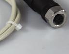
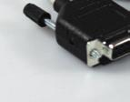
5 GUI description isys-00 speed and distance sensor. connecting the isys-00 to your PC To connect the isys-00 with your PC use the following configuration (complete cables can be purchased from InnoSenT). M M 9 M M 9 Input isys-00 Pin # Signal Pin # OUT Pin # Output Input Pin # SignalOUT OUTOUT Output OUT VCC OUTGND VCC not connected RS GND GND RS 7 not connected RS_Rx GND RS_Tx 7 RS_Rx RS_Tx RS-Connector RS-Connector isys-00 / isys-00 Signal Pin # OUT OUT OUT VCC GND RSRS RS RSRS GND RS RS 7 RS_A RS RS RS_B RS 7 7 Input Output Pin # not connected Connector A-type compatible to SACC-M-SCO PLUG (PN: 9) from Phoenix Contacts The sensor has a RS or RS interface (depending on sensor-type). An isys-00 with RS interface can be connected directly to the COM port of the PC otherwise there can be a RS to USB adapter used. The Adapter installs a virtual COM port which can be selected in the GUI.. installing isys-00 GUI Software is (Service -> Downloads) Copy installer isys00x_gui_setup to your harddisk. Double-click on isys00x_gui_setup to start SetupWizard. Follow instructions. Click Finish to close setup and to launch GUI. Experience and Reliability in Radar-Technology -
 click Connect click Close click to configure COM Port During the")


6 isys-00 speed and distance sensor GUI description. start screen After launching the GUI the start screen apears. To connect the isys-00 sensor to the GUI click COM Port Config select your COM-Port set baud rate set device address (default=) click Connect click Close click to configure COM Port During the connection process the GUI reads some parameters from the Sensor. The red lamp in the connection window switches to green if successfull. Default baud rates: isys-00 isys-00 isys-00 select COM-Port set baud rate to Baud 00 Baud 9 00 Baud click to connect The device address is only for RS communication interface required. Adapt this address in case of RS interface to the devices address you want to connect.. Live Stream A click on Start Live Stream starts displaying the live data in the opened tab.. Freeze/Run For an improved analysis of the sensor data, the display can be frozen by clicking on Freeze. To enable the live data again click on Run... Write all Params tp EEProm This command writes all data into the EEPROM. This command is mandatory after setting all your parameters, otherwise all configurations made are lost.. Save - Load configuration Short Range.ipf To configure more than one sensor with the same settings all parameters can be saved in an *.ipf file.. Save configuration to file By clicking on File => Save configuration to file the actual parameters will be saved in an *.ipf file... Load configuration from file By clicking on File => Load configuration from file parameter sets can be loaded. To write these parameters to the sensor click on Write all parameters to EEProm otherwise the settings are lost after shutdown the sensor. The Standard configuration is the Short Range parameter set (compare table beside). Other parameters sets are click to start Live View output approaching & receding active low, if object exist active high, if NO object exist output approaching active high, if object exist active low, if NO object exist output receding active high, if object exist active low, if NO object exist rising delay falling delay 7ms 7ms filter type highest amplitude single target filter 0% for all outputs amplification 0dB distance range 0...0m detection level 0dB - Experience and Reliability in Radar-Technology


7 GUI description isys-00 speed and distance sensor. frequency channels To avoid interferences if two sensors are mounted close to each other different frequency channels can be selected. click Config select use channel or use channel for using the sensor in Europe select use channel or use channel for using the sensor in the US Channel is corresponding to a transmit frequency of.90ghz Channel is corresponding to a transmit frequency of.0ghz Channel is corresponding to a transmit frequency of.ghz Channel is corresponding to a transmit frequency of.ghz 7. option Raw Signal The Option Raw Signals can be used to view the analog received signals. The raw signals tab shows the signal raw data which sampled by the analog to digital converter. Alternatively the user can switch to the FFT signal (Tab Detection ). The FFT and threshold are calculated by the sensor.. tab Detection This tab shows the FFT and the threshold calculated by the radar sensor. The threshold consists of three parts: adaptive value, height of the threshold depending on the noise level low-pass filter, for the frequency selection of the different objects user defined threshold value, will be added to the threshold.. User defined threshold values If the adaptive calculated threshold is lower than the minimum value it is set to the minimum. Change the sensitivity to vary the number of detections. Set these values by adjusting the slider or by setting the level in db... Linefilter By activating the Line Filters several frequencies can be cancelled. This can be used for example to prevent interference from fluorescent lamps. Experience and Reliability in Radar-Technology - 7 7
, the signal will be increased.")


8 isys-00 speed and distance sensor GUI description 9. automatic amplification An automatic amplification can be activated in Config => Amplification. If the radar signals does not exceed the inner threshold (orange area), the signal will be increased. If the radar signal exceeds the inner threshold, but does not exceed the outer threshold (green area), nothing happens to the signal amplification (signal is inside hysteresis). If the radar signal exceeds the outer thershold, the signal amplification will be decreased. 0. output signals - The isys-00 offers output signals that can be activated and configured indepentendly of each other. The tabs Output, Output and Output shows the different target lists. Each target list has separate filter parameters which can be changed in the specific output tab. During a live stream a coloured button shows the actual status of the detected object: Green object is receding Red object is approaching Orange no object detected The output can filtered by the Target Filter Type menu. Possible settings are: activate / deactivate target filter smoothing level highest Amplitude mean velocity mean range median velocity median range The selection of the wanted option has a direct influence to the signals in the GUI as well as on the Output Configuration. Show Histogram By activating the Histogram option you can follow the time dependent trend of changes in speed and range of the object(s). - Experience and Reliability in Radar-Technology

9 GUI description isys-00 speed and distance sensor. target filter options The target filter options declare the velocity-, range- and signalarea within the sensor is able to detect objects. Velocity has an additional option to set the sign of the velocity to detect only receeding or approaching objects. The filters can be set in the following range: isys-00 isys-00/ isys-00 Speed range: Distance range : Distance range : Signal Level: 0...0km/h 0...0m 0...0m 0...0dB Speed range: Distance range : Distance range : Signal Level: 0...0km/h 0...0m 0...0m 0...0dB. output configuration To configure the output signals go to menu isys => Output Configuration The output PINs can be activated and configured seperately from each other. Possible setting of output type are: digital pwm (velocity) pwm (range) In case of pwm a pulse-width modulated signal will be send to the output PINs corresponding to the speed or range of the objects (depending on which option is selected) Output PIN configuration: configuration description target detected output pin state active low - normally open low side switch yes high impedance active low - normally open low side switch no connected to GND active low - normally closed low side switch yes connected to GND active low - normally closed low side switch no high impedance active high - normally open high side switch no high impedance active high - normally open high side switch yes connected to VCC active high - normally closed high side switch no connected to VCC active high - normally closed high side switch yes high impednace totem pole - normally open push-pull no connected to GND totem pole - normally open push-pull yes connected to VCC totem pole - normally closed push-pull no connected to VCC totem pole - normally closed push-pull yes connected to GND Experience and Reliability in Radar-Technology - 9 9


10 isys-00 speed and distance sensor GUI description. manual amplification The isys-00 sensor features a variable IF amplification with an Bit digital potentiometer. For changing the amplification, open the slider window in the Config menu under Amplification. The button Store stores all actual set parameters including the amplification into the devices EEPROM. The figures beside are showing the amplification for the different potentiometer positions.. record & playback The isys-00 radar sensor features a record & playback functionality for raw data, fft & threshold and Targetlist. Depending on the active tab the specific data is recorded. record: Start recording with record button. Stop recording with stop button and chose file name and storage location. A filename including date and time is suggested. playback: Open playback window with play button. After opening a recoded file (xx.log) the playback can be started. Set the playback speed by adjusting the cycle time.. GUI setting Open in the GUI setting window in the Config menu. Change the units as useful for the measurements Experience and Reliability in Radar-Technology


11 GUI description isys-00 speed and distance sensor. Change RS address Changing RS address is a special feature of the isys-00 and isys-00. Open the slider window in the Help menu under About. Set the new device address and click set. After changing the device address the command acknowledge is send with the new device address. Note: The address is written directly to the EEPROM. 7. Change RS / RS baudrate The isys-00 sensor supports different baudrates. For changing the baudrate, open the slider window in the Config menu under Change Baudrate. Select new baudrate in dropdown menu and click Change Baudrate. Note: The baudrate is written directly to the EEPROM. Experience and Reliability in Radar-Technology -


 select new firmware version (*.")
12 isys-00 speed and distance sensor GUI description. Firmware. firmware update menue To start the firmware update go to menue Help => about. sensor/gui information () Information about the actual sensor firmware and GUI software. firmware update () To start the firmware update select update () select new firmware version (*.hex - file) () confirm with button flash firmware () wait until progress bar reaches 00% () () () - Experience and Reliability in Radar-Technology


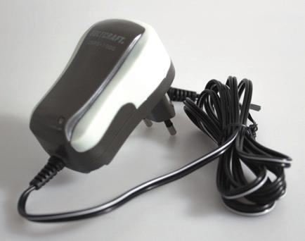
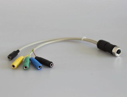


13 GUI description isys-00 speed and distance sensor contact information If you have any questions please contact us! Corinna Mergenthal Tel.: Martin Maidhof Tel.: part numbers P/N: isys-00 P/N: isys-prog_adap Experience and Reliability in Radar-Technology - P/N: isys-pow_adap P/N: isys-pow_sup

14 Contact Details: Tel:
isys-4004 GUI interface - V2.1 Power up Initialize Peripheral Start Measurement YES LED flashes red Object available LED blinking
 isys-4004 GUI interface - V2.1 Power up Initialize Peripheral Start Measurement Mode Object available YES LED flashes red NO LED blinking isys-4004 distance sensor GUI description content 1. connecting
RigExpert TI-7 USB Transceiver Interface User s manual
 RigExpert TI-7 USB Transceiver Interface User s manual Please read this manual before attempting to use the RigExpert TI-7 device. - - 2 - Table of contents 1. What is a RigExpert TI-7?... 4 2. Specifications...
TI RigExpert. User s manual. USB Transceiver Interface
 TI-5000 RigExpert USB Transceiver Interface User s manual . Table of contents Introduction Operating the TI-5000 Front and rear panels Transceiver and computer connection Updating the firmware Annexes
Ocean Controls KT-5221 Modbus IO Module
 Ocean Controls Modbus IO Module 8 Relay Outputs 4 Opto-Isolated Inputs 2 Analog Inputs (10 bit) 1 PWM Output (10 bit) 4 Input Counters Connections via Pluggable Screw Terminals 0-5V or 0-20mA Analog Inputs,
MAX11300PMB1 Peripheral Module and Munich (USB2PMB1) Adapter Board Quick Start Guide
 Adapter Board Quick Start Guide") MAX11300PMB1 Peripheral Module and Munich (USB2PMB1) Adapter Board Quick Start Guide Rev 0; 7/14 For pricing, delivery, and ordering information, please contact Maxim Direct at 1-888-629-4642, or visit
MAX11300PMB1 Peripheral Module and Munich (USB2PMB1) Adapter Board Quick Start Guide Rev 0; 7/14 For pricing, delivery, and ordering information, please contact Maxim Direct at 1-888-629-4642, or visit
Pololu Jrk USB Motor Controller
 Pololu Jrk USB Motor Controller User's Guide 1. Overview.................................................... 2 1.a. Module Pinout and Components.................................... 4 1.b. Supported Operating
VBRC 4. Radio Communicator. Installer Manual
 VBRC 4 Radio Communicator Installer Manual 17 December 2014 CONTENT 1. INTRODUCTION...3 2. SYSTEM STRUCTURE...3 3. SYSTEM PROGRAMMING WITH PC SOFTWARE...5 4. TROUBLESHOOTING...6 5. FIRMWARE UPGRADE...7
Topcon Receiver Utility: GNSS Receiver Firmware Update Process. Oscar R. Cantu
 Topcon Receiver Utility: GNSS Receiver Firmware Update Process Oscar R. Cantu TRU: GNSS Receiver Firmware Update Topcon Receiver Utility (TRU), product definition Office Processing and Reporting Software
Electronic regulator for PWM controlled proportional solenoid valves FABER -
 Electronic regulator for PWM controlled proportional solenoid valves STU Control Unit FABER - COM DESCRIPTION STU-PWM electronic card is a regulator for proportional solenoid valves, which can drive up
DragonLink Advanced Transmitter
 DragonLink Advanced Transmitter A quick introduction - to a new a world of possibilities October 29, 2015 Written by Dennis Frie Contents 1 Disclaimer and notes for early release 3 2 Introduction 4 3 The
SonoLab Echo-I User Manual
 SonoLab Echo-I User Manual Overview: SonoLab Echo-I is a single board digital ultrasound pulse-echo solution. The system has a built in 50 volt high voltage generation circuit, a bipolar pulser, a transmit/receive
Objectives: Learn what an Arduino is and what it can do Learn what an LED is and how to use it Be able to wire and program an LED to blink
 Objectives: Learn what an Arduino is and what it can do Learn what an LED is and how to use it Be able to wire and program an LED to blink By the end of this session: You will know how to use an Arduino
PWM P108. Programming Instructions v 3.2 PWM Controller Software
 PWM P108 Programming Instructions v 3.2 PWM Controller Software PWM P108 Programming Instructions v 3.2 for PWM Controller Software Download / Install & Run Driver (Must be installed for software to work)
RSP1 Evaluation Kit User Manual
 RSP Evaluation Kit User Manual RFbeam Microwave GmbH www.rfbeam.ch Page /8 RSP Evaluation Kit Features Reference design for RFbeam RSP processor Advanced movement detection system High performance signal
Ultrasonic Multiplexer OPMUX v12.0
 Przedsiębiorstwo Badawczo-Produkcyjne OPTEL Sp. z o.o. ul. Morelowskiego 30 PL-52-429 Wrocław tel.: +48 (071) 329 68 54 fax.: +48 (071) 329 68 52 e-mail: optel@optel.pl www.optel.eu Ultrasonic Multiplexer
Channels that are not occupied by temperature sensors, can take over alternative functions:
 Firmware /TEMP12 The /TEMP12 firmware allows you to connect up to twelve digital temperature sensors (type Dallas DS18B20). Data from twelve channels is transferred to your PC via USB. ONE temperature
Page 1/10 Digilent Analog Discovery (DAD) Tutorial 6-Aug-15. Figure 2: DAD pin configuration
 Tutorial 6-Aug-15. Figure 2: DAD pin configuration") Page 1/10 Digilent Analog Discovery (DAD) Tutorial 6-Aug-15 INTRODUCTION The Diligent Analog Discovery (DAD) allows you to design and test both analog and digital circuits. It can produce, measure and
Page 1/10 Digilent Analog Discovery (DAD) Tutorial 6-Aug-15 INTRODUCTION The Diligent Analog Discovery (DAD) allows you to design and test both analog and digital circuits. It can produce, measure and
VBRC 5. Radio Communicator. Installer Manual
 VBRC 5 Radio Communicator Installer Manual 10 / 10 / 2013 CONTENT 1. INTRODUCTION...3 2. SYSTEM STRUCTURE...3 3. SYSTEM PROGRAMMING WITH PC SOFTWARE...5 4. TROUBLESHOOTING...6 5. FIRMWARE UPGRADE...7 6.
BandMaster V Manual. Installation
 BandMaster V Manual Installation Installing and configuring the BM-5 BandMaster V is a simple process. All the configuration process is done from the front panel. Installation and configuration steps are
EVDP610 IXDP610 Digital PWM Controller IC Evaluation Board
 IXDP610 Digital PWM Controller IC Evaluation Board General Description The IXDP610 Digital Pulse Width Modulator (DPWM) is a programmable CMOS LSI device, which accepts digital pulse width data from a
USB Multifunction Arbitrary Waveform Generator AWG2300. User Guide
 USB Multifunction Arbitrary Waveform Generator AWG2300 User Guide Contents Safety information... 3 About this guide... 4 AWG2300 specifications... 5 Chapter 1. Product introduction 1 1. Package contents......
WTDIN-M. eeder. Digital Input Module. Technologies FEATURES SPECIFICATIONS DESCRIPTION. Weeder Technologies
 eeder Technologies 90-A Beal Pkwy NW, Fort Walton Beach, FL 32548 www.weedtech.com 850-863-5723 Digital Input Module FEATURES 8 wide-range digital input channels with high voltage transient protection.
Answering frequently asked Questions (Firmware V.107)
") FAQ EasyConn Profibus plug Answering frequently asked Questions (Firmware V.107) EasyConn LEDs: While connected, the Profibus connector offers the following test functions for start-up and trouble shooting
FAQ EasyConn Profibus plug Answering frequently asked Questions (Firmware V.107) EasyConn LEDs: While connected, the Profibus connector offers the following test functions for start-up and trouble shooting
User Guide SiRad Easy Evaluation Kit
 Silicon Radar GmbH Im Technologiepark 1 15236 Frankfurt (Oder) Germany fon +49.335.557 17 60 fax +49.335.557 10 50 http://www.siliconradar.com support@siliconradar.com User Guide SiRad Easy Evaluation
Software Operational Manual
 Software Operational Manual for Easy Servo Drives ES-D508/808/1008 www.leadshine.com SM-ES-R20121030 ii Leadshine reserves the right to make changes without further notice to any products herein to improve
Coding with Arduino to operate the prosthetic arm
 Setup Board Install FTDI Drivers This is so that your RedBoard will be able to communicate with your computer. If you have Windows 8 or above you might already have the drivers. 1. Download the FTDI driver
ROTATING SYSTEM T-12, T-20, T-50, T- 150 USER MANUAL
 ROTATING SYSTEM T-12, T-20, T-50, T- 150 USER MANUAL v. 1.11 released 12.02.2016 Table of contents Introduction to the Rotating System device 3 Device components 4 Technical characteristics 4 Compatibility
MityCAM-B2521 EPIX XCAP User s Guide
 MityCAM-B2521 EPIX XCAP User s Guide (CT031 Revision 1) Page 1 of 13 60-000014 Contents 1 Installing Laptop Express Card... 3 2 Using the Camera in Single Camera Link mode (Laptop)... 3 3 Single Camera
IX Feb Operation Guide. Sequence Creation and Control Software SD011-PCR-LE. Wavy for PCR-LE. Ver. 5.5x
 IX000693 Feb. 015 Operation Guide Sequence Creation and Control Software SD011-PCR-LE Wavy for PCR-LE Ver. 5.5x About This Guide This PDF version of the operation guide is provided so that you can print
USB-MC USB Motion Controller
 USB-MC USB Motion Controller Con2 I/O port, to I/O card Con4 Aux port, inputs and outputs Con3 parallel port, to I/O card Con1 USB port to PC Con5 external power supply 8 24 VDC Status LED - + Comm. LED
BiSS Interface AN18: BiSS C ANALYZER
 Rev A3, Page 1/7 CONTENTS BASIC OPERATION 1 Clock rates................... 1 BiSS analyzer modes............. 2 2 BiSS ANALYZER INSTALLATION 2 ELECTRICAL INTERFACE 2 RS422 BiSS Encoder Interface........
EULAMBIA ADVANCED TECHNOLOGIES LTD. User Manual EAT-EOM-CTL-2. Alexandros Fragkos
 EULAMBIA ADVANCED TECHNOLOGIES LTD User Manual Alexandros Fragkos (alexandros.fragkos@eulambia.com) 11/28/2016 28/11/2016 User Manual User Manual 28/11/2016 Electro-Optic Modulator Bias Control Unit v2.0
Configuring a Mitsubishi PLC CC-Link Network
 Configuring a Mitsubishi PLC CC-Link Network Author: Sam Stewart/Kade Olson Date: May 10, 2017 Introduction AcraDyne Gen IV Controllers are available with CC-Link (Version 1 and 2) communication capability.
RTKWARE UBR1 Technical Datasheet. ver1.1 (29/04/2015)
") RTKWARE UBR1 Technical Datasheet ver1.1 (29/04/2015) Table of Contents Table of Contents... 2 Overview... 3 Key-Features... 3 Applications... 3 Functional diagrams... 4 Power Distribution... 4 Data...
RTKWARE UBR1 Technical Datasheet ver1.1 (29/04/2015) Table of Contents Table of Contents... 2 Overview... 3 Key-Features... 3 Applications... 3 Functional diagrams... 4 Power Distribution... 4 Data...
Instruction Manual. Ultrasonic and Radar
 Instruction Manual ABM Gateway Software for 3 & 4 wire Ultrasonic and Radar Instruction Manual Revision 5.8 NOTE: Windows 7 and 8 users are asked to use default screen size (100%). To change from Larger
R5 RIC Quickstart R5 RIC. R5 RIC Quickstart CONTENTS. Saab TransponderTech AB. Appendices. Project designation. Document title
 Appendices 1 (10) Project designation R5 RIC Document title CONTENTS 1 Installation... 2 1.1 Connectors... 2 1.1.1 Power... 2 1.1.2 Video... 2 1.1.3 Sync... 3 1.1.4 RS232/ARP/ACP... 3 1.1.5 Radar data...
STPDRV-1 Stepper Motor Driver Data Sheet (R1.0) BFF Design Ltd
 BFF Design Ltd") STPDRV-1 Stepper Motor Driver Data Sheet (R1.0) BFF Design Ltd 1. Introduction The BFF STPDRV-1 card is a bi-polar stepper motor driver. It is designed to drive the BFF Motorised Trim Wheel or other user-designed
STPDRV-1 Stepper Motor Driver Data Sheet (R1.0) BFF Design Ltd 1. Introduction The BFF STPDRV-1 card is a bi-polar stepper motor driver. It is designed to drive the BFF Motorised Trim Wheel or other user-designed
LV8716QAGEVK Evaluation Kit User Guide
 LV8716QAGEVK Evaluation Kit User Guide NOTICE TO CUSTOMERS The LV8716QA Evaluation Kit is intended to be used for ENGINEERING DEVELOPMENT, DEMONSTRATION OR EVALUATION PURPOSES ONLY and is not considered
INSTRUCTION MANUAL FOR ULTRASONIC/MICROWAVE SENSORS
 INSTRUCTION MANUAL FOR ULTRASONIC/MICROWAVE SENSORS 1)Install PROBE_GatewayPC Software on PC.Remove previous installation. In Windows Control Panel go to the Programs and Features, select Probe_GatewayPC_Net
Simplified Operations for TM-3100 Series Digital Tachometer
 Simplified Operations for TM-3100 Series Digital Tachometer The TM-3100 series Digital Tachometers has the most fundamental function in rotational measurement of four standard models (rotation speed display,
Interface Genius Modem Instruction Manual v1.2.4
 Interface Genius Modem Instruction Manual v1.2.4 Interface Genius Modem is a USB / LAN controlled SO2R radio interface remote radio modem. It is designed to be controlled by a Windows application, and
Blue Bamboo P25 Device Manager Guide
 Blue Bamboo P25 Device Manager Guide Version of Device Manager: 1.1.28 Document version: 2.3 Document date: 2011-09-20 Products: P25 / P25-M / P25i / P25i-M BLUE BAMBOO Headquarters Blue Bamboo Transaction
USER MANUAL Z-8TC. Via Germania, Z.I. CAMIN PADOVA ITALY. Via Svizzera, Z.I. CAMIN PADOVA ITALY
 USER MANUAL Z-8TC SENECA s.r.l. Via Germania, 34 35127 Z.I. CAMIN PADOVA ITALY Via Svizzera, 17 35127 Z.I. CAMIN PADOVA ITALY Tel. +39.049.8705355 8705359 Fax. +39.049.8706287 Web site: www.seneca.it Technical
TMC603EVAL MANUAL Evaluation board for the TMC603 three phase motor driver with BLDC back EMF commutation hallfx
 TMC603EVAL MANUAL Evaluation board for the TMC603 three phase motor driver with BLDC back EMF commutation hallfx TRINAMIC Motion Control GmbH & Co. KG Sternstraße 67 D 20357 Hamburg GERMANY www.trinamic.com
Guardian and DL3282 Modem Interface Technical Service Application Note
 Guardian and DL3282 Modem Interface Technical Service Application Note OVERVIEW The following document is designed to provide information for the implementation of the Guardian Wireless Modem/Analog Radio
WTDOT-M. eeder. Digital Output Module. Technologies FEATURES SPECIFICATIONS DESCRIPTION. Weeder Technologies
 eeder Technologies 90-A Beal Pkwy NW, Fort Walton Beach, FL 32548 www.weedtech.com 850-863-5723 Digital Output Module FEATURES 8 high-current open-collector output channels with automatic overload shutdown.
SC16A SERVO CONTROLLER
 SC16A SERVO CONTROLLER User s Manual V2.0 September 2008 Information contained in this publication regarding device applications and the like is intended through suggestion only and may be superseded by
TECHNICAL DATASHEET #TDAX Universal Input, Single Output Valve Controller CAN (SAE J1939)
") Features: TECHNICAL DATASHEET #TDAX021610 Universal Input, Single Output Valve Controller CAN (SAE J1939) 1 universal signal input (voltage, current, resistive, PWM, frequency or digital) 1 output: proportional
Features: TECHNICAL DATASHEET #TDAX021610 Universal Input, Single Output Valve Controller CAN (SAE J1939) 1 universal signal input (voltage, current, resistive, PWM, frequency or digital) 1 output: proportional
The GPS Smart Coupler II Installation/User Manual
 The GPS Smart Coupler II Installation/User Manual Porcine Associates 244 O Connor Street Menlo Park, CA 94025 (650) 326-2669 Fax (650) 326-1071 www.porcine.com 3.15 Table of Contents THE GPS SMART COUPLER
Analog Discovery Arbitrary Function Generator for Windows 7 by Mr. David Fritz and Ms. Ellen Robertson
 Analog Discovery Arbitrary Function Generator for Windows 7 by Mr. David Fritz and Ms. Ellen Robertson Financial support to develop this tutorial was provided by the Bradley Department of Electrical and
TECHNICAL DATASHEET #TDAX ISOLATED DUAL CHANNEL UNIVERSAL SIGNAL CONVERTER
 Preliminary TECHNICAL DATASHEET TDAX130540 ISOLATED DUAL CHANNEL UNIVERSAL SIGNAL CONVERTER 2 Analog (Bipolar), Resistive, Digital, Frequency (RPM) or PWM Signal Inputs Encoder Input Magnetic Pick Up Input
Studuino Icon Programming Environment Guide
 Studuino Icon Programming Environment Guide Ver 0.9.6 4/17/2014 This manual introduces the Studuino Software environment. As the Studuino programming environment develops, these instructions may be edited
LC-10 Chipless TagReader v 2.0 August 2006
 LC-10 Chipless TagReader v 2.0 August 2006 The LC-10 is a portable instrument that connects to the USB port of any computer. The LC-10 operates in the frequency range of 1-50 MHz, and is designed to detect
SSI-4 PLUS User Manual
 SSI-4 PLUS User Manual 1 SSI-4 PLUS... 2 1.1 Getting to Know the SSI-4 PLUS... 2 1.2 Channel Functions... 3 2 Wiring and Setup... 3 2.1 Powering the SSI-4 PLUS... 3 2.2 5V for External Sensors... 4 2.3
Using the SparkFun PicoBoard and Scratch
 Page 1 of 7 Using the SparkFun PicoBoard and Scratch Introduction Scratch is an amazing tool to teach kids how to program. Often, we focus on creating fun animations, games, presentations, and music videos
Application Note. Communication between arduino and IMU Software capturing the data
 Application Note Communication between arduino and IMU Software capturing the data ECE 480 Team 8 Chenli Yuan Presentation Prep Date: April 8, 2013 Executive Summary In summary, this application note is
SIMREX Corporation Your Trusted Wireless Solution Provider
 SIMSYNC Instruction Manual Traffic Controller Time Synchronization System Firmware Release 1.7 SIMREX MAN.SIMSYNC, Rev 8.0 MARCH 2006 Your Trusted Wireless Solution Provider www.simrex.com Introduction
Disable Windows Sounds
 9/28/2017 - K3CT Disable Windows Sounds Users may want to disable the Windows Sounds so none of the Windows OS sounds are transmitted on the radio. Install the Icom Drivers, Select COM port, Disable Power
Motion Controller 2-Quadrant PWM for Brushless DC-Servomotors
 Motion Controller -Quadrant PWM for Brushless DC-Servomotors Series BLD 0 Series BLD 0 Operating Instructions Miniature Drive Systems Micro Drives DC-Micromotors Precision Gearheads Servo Components Drive
User Guide SiRad Simple Evaluation Kit
 Silicon Radar GmbH Im Technologiepark 1 15236 Frankfurt (Oder) Germany fon +49.335.557 17 60 fax +49.335.557 10 50 http://www.siliconradar.com support@siliconradar.com User Guide SiRad Simple Evaluation
Interfacing Clockaudio microphones with the Logic Box
 Interfacing Clockaudio microphones with the INTRODUCTION One popular application for the is to interface with conferencing microphones that feature mute switches and LED indicators, and Clockaudio is a
Baudrate Conversion Options For Brookhouse NMEA multiplexers models AIS and AISC
 Baudrate Conversion Options For Brookhouse NMEA multiplexers models AIS and AISC Three baudrate conversion options are offered in the multiplexer setup menu (menu options 5, 6 and 7 for baudrate conversion
Tarocco Closed Loop Motor Controller
 Contents Safety Information... 3 Overview... 4 Features... 4 SoC for Closed Loop Control... 4 Gate Driver... 5 MOSFETs in H Bridge Configuration... 5 Device Characteristics... 6 Installation... 7 Motor
High Current DC Motor Driver Manual
 High Current DC Motor Driver Manual 1.0 INTRODUCTION AND OVERVIEW This driver is one of the latest smart series motor drivers designed to drive medium to high power brushed DC motor with current capacity
Veyron Servo Driver (24 Channel) (SKU:DRI0029)
 (SKU:DRI0029)") Veyron Servo Driver (24 Channel) (SKU:DRI0029) From Robot Wiki Contents 1 Introduction 2 Specifications 3 Pin Definitions 4 Install Driver o 4.1 Windows OS Driver 5 Relationship between Steering Angle
Veyron Servo Driver (24 Channel) (SKU:DRI0029) From Robot Wiki Contents 1 Introduction 2 Specifications 3 Pin Definitions 4 Install Driver o 4.1 Windows OS Driver 5 Relationship between Steering Angle
Blue Point Engineering
 Blue Point Engineering Instruction I www.bpesolutions.com Pointing the Way to Solutions! Animatronic Wizard - 3 Board (BPE No. WAC-0030) Version 3.0 2009 Controller Page 1 The Wizard 3 Board will record
Берг АБ Тел. (495) , факс (495) Initial operation and diagnosis
 , факс (495) Initial operation and diagnosis") Axial/radial bearings with integral measuring system Initial operation and diagnosis Fitting and maintenance instructions MON 18 This technical publication has been produced with a great deal of care and
Axial/radial bearings with integral measuring system Initial operation and diagnosis Fitting and maintenance instructions MON 18 This technical publication has been produced with a great deal of care and
GPS Time Server Product Specifications and Installation Data
 GPS Time Server Product Specifications and Installation Data 1 DESCRIPTION This document covers Revision C and higher. The HE200TIM100 is a GPS (Global Positioning System) Time Server that monitors GPS
Example KodeKLIX Circuits
 Example KodeKLIX Circuits Build these circuits to use with the pre-installed* code * The code is available can be re-downloaded to the SnapCPU at any time. The RGB LED will cycle through 6 colours Pressing
HAW-Arduino. Sensors and Arduino F. Schubert HAW - Arduino 1
 HAW-Arduino Sensors and Arduino 14.10.2010 F. Schubert HAW - Arduino 1 Content of the USB-Stick PDF-File of this script Arduino-software Source-codes Helpful links 14.10.2010 HAW - Arduino 2 Report for
M2M i-link POINT-TO-MULTIPOINT INSTALLATION INSTRUCTIONS
 M2M i-link POINT-TO-MULTIPOINT INSTALLATION INSTRUCTIONS 1 TABLE OF CONTENTS 1 TABLE OF CONTENTS... 2 2 GENERAL... 3 3 INSTALLATION... 4 3.1 SUB-STATIONS... 4 3.2 MAIN STATION (PC)... 4 4 CONNECTING THE
FABO ACADEMY X ELECTRONIC DESIGN
 ELECTRONIC DESIGN MAKE A DEVICE WITH INPUT & OUTPUT The Shanghaino can be programmed to use many input and output devices (a motor, a light sensor, etc) uploading an instruction code (a program) to it
Micro Wizard Instructions
 How to install your Fast Track flashing light display timer model K1 with optional remote start switch (If you have ordered the Quick Mount or have a Best Track, disregard this section and refer to the
WTPCT-M. eeder. Pulse Counter/Timer Module. Technologies FEATURES SPECIFICATIONS DESCRIPTION. Weeder Technologies
 eeder Technologies 90-A Beal Pkwy NW, Fort Walton Beach, FL 32548 www.weedtech.com 850-863-5723 Pulse Counter/Timer Module FEATURES Reads frequency from 0.50000 to 1,400,000 Hz using 5 digit resolution
OVEN INDUSTRIES, INC. Model 5C7-362
 OVEN INDUSTRIES, INC. OPERATING MANUAL Model 5C7-362 THERMOELECTRIC MODULE TEMPERATURE CONTROLLER TABLE OF CONTENTS Features... 1 Description... 2 Block Diagram... 3 RS232 Communications Connections...
MiniProg Users Guide and Example Projects
 MiniProg Users Guide and Example Projects Cypress MicroSystems, Inc. 2700 162 nd Street SW, Building D Lynnwood, WA 98037 Phone: 800.669.0557 Fax: 425.787.4641 1 TABLE OF CONTENTS Introduction to MiniProg...
INSTRUCTION MANUAL IP REMOTE CONTROL SOFTWARE RS-BA1
 INSTRUCTION MANUAL IP REMOTE CONTROL SOFTWARE RS-BA FOREWORD Thank you for purchasing the RS-BA. The RS-BA is designed to remotely control an Icom radio through a network. This instruction manual contains
Using the 9XR Pro for More than Eight Channels
 Appendix B Using the 9XR Pro for More than Eight Channels Introduction In stock form, with a module such as the FrSky DJT or OrangeRx DSMX/DSM2 installed, the Turnigy 9XR Pro transmitter can control a
Instruction Manual ABM HART Gateway Software. Instruction Manual Revision A.1
 Instruction Manual ABM HART Gateway Software Instruction Manual Revision A.1 Table of Contents Section 1: Getting Started... 3 1.1 Setup Procedure... 3 1.2 Quick Setup Guide for Ultrasonic Sensors... 11
User manuel. Hybrid stepper servo drive
 User manuel Hybrid stepper servo drive 1 Overview Hybridstepper servo drive system integrated servo control technology into the digital step driver. It adopts typical tricyclic control method which include
Features. General Description. EV Kit Contents. EV Kit Photo
 MAX785 Evaluation Kit Evaluates: MAX785 General Description The MAX785 evaluation kit (EV kit) provides the hardware and software graphical user interface (GUI) necessary to evaluate the MAX785 6-channel
One of the key features of the BoC is that it s easy to configure the board over the DMX network.
 SkullTroniX Board Of Chuckie configuration tool One of the key features of the BoC is that it s easy to configure the board over the DMX network. DMX address Upper and lower hard stop limits for servos
Zybo Z7 Pcam 5C Demo
 Zybo Z7 Pcam 5C Demo The demo in action - displaying the Pcam 5C data. Overview Description The Zybo Z7 Pcam 5C project demonstrates the usage of the Pcam 5C as a video source by forwarding the streaming
GPS Evaluation Kit EVA1084-A
 GPS Evaluation Kit EVA1084-A A Description of the Evaluation Board for Vincotech s GPS Receiver Modules A1084-A/-B User s Manual Version 1.0 Hardware Revision 01 V1.0 Jan-09 User s Manual Page 1 of 18
Height Limited Switch
 Height Limited Switch Manual version: 1.0 Content Introduction...3 How it works...3 Key features...3 Hardware...4 Motor cut-off settings...4 Specification...4 Using the RC HLS #1 module...5 Powering the
LCC-100 software User manual
 User Manual Pressure Temperature Humidity Air Velocity Airflow Sound level New LCC-100 software User manual Configuration software for Monostats - Class 50 and 100 units - ranges - relays - set points
User Manual EnOcean V 0.1
 & User Manual EnOcean V 0.1 Last update: July 2012 All software-related descriptions refer to the software V1279. We recommend to update older versions of the system. Small deviations in the description
USB-UART RADIO MODULE(WM11TR_ L_02_USB)
") Documents Version: 2.05 Document No. 2012-0046-E Copyright is reserved by Rping Group Limited (2008-2015) USB-UART RADIO MODULE(WM11TR_ L_02_USB) USER GUIDE 82469790 Index Documents Version: 2.05... 1
Documents Version: 2.05 Document No. 2012-0046-E Copyright is reserved by Rping Group Limited (2008-2015) USB-UART RADIO MODULE(WM11TR_ L_02_USB) USER GUIDE 82469790 Index Documents Version: 2.05... 1
BRB900 GPS Telemetry System August 2013 Version 0.06
 BRB900 GPS Telemetry System August 2013 Version 0.06 As of January 2013, a new model of the BRB900 has been introduced. The key differences are listed below. 1. U-blox GPS Chipset: The Trimble Lassen IQ
Arduino Workshop 01. AD32600 Physical Computing Prof. Fabian Winkler Fall 2014
 AD32600 Physical Computing Prof. Fabian Winkler Fall 2014 Arduino Workshop 01 This workshop provides an introductory overview of the Arduino board, basic electronic components and closes with a few basic
2F. No.25, Industry E. 9 th Rd., Science-Based Industrial Park, Hsinchu, Taiwan Application Note of OGM220, AN001 V1.8
 Application Note of OGM220, AN001 V1.8 1.0 Introduction OGM220 series is a dual channels NDIR module having a digital output directly proportional to CO2 concentration. OGM220 is designed for multi-dropped
MDM5253 DC Motor Driver Module with Position and Current Feedback User Manual
 MDM5253 DC Motor Driver Module with Position and Current Feedback User Manual Version: 1.0.3 Apr. 2013 Table of Contents I. Introduction 2 II. Operations 2 II.1. Theory of Operation 2 II.2. Running as
Assembly Instructions
 Assembly Instructions optocontrol 2520 Functions Edge measurement with the shadow principle (Edge low-high; edge high-low) Measurement of diameter-, width-, gap incl. center axis Counting of edges or segments,
MBD-8F Automatic Antenna Switch Controller
 - 1 - MBD-8F Automatic Antenna Switch Controller MBD-8F is an intelligent controller compatible with all eight-antenna switches manufactured by Hamplus. It has a band decoder to receive the information
User s Manual Software Edition 1.7
 ScanView User s Manual Software Edition 1.7 The information in this document is subject to change without notice and should not be construed as a commitment by Sitronic GmbH. While every effort has been
LVTX-10 Series Ultrasonic Sensor Installation and Operation Guide
 LVTX-10 Series Ultrasonic Sensor Installation and Operation Guide M-5578/0516 M-5578/0516 Section TABLE OF CONTENTS 1 Introduction... 1 2 Quick Guide on Getting Started... 2 Mounting the LVTX-10 Series
Configuration Program for OZ4HZ Version 2 Tracker (rev ).
.") Configuration Program for OZ4HZ Version 2 Tracker (rev. 2008-12-08). The tracker is configured with a Windows program witch can be downloaded from the website. www.aargang64.dk/aprs Use a standard null-modem
Configuration Program for OZ4HZ Version 2 Tracker (rev. 2008-12-08). The tracker is configured with a Windows program witch can be downloaded from the website. www.aargang64.dk/aprs Use a standard null-modem
TEGAS. engineering TE-TAP. Timing advance processor. User manual. Ver.1.04 ( )
") TE-TAP Timing advance processor User manual www.tegas.lt Ver..0 (05.09.0) Device description Single channel time advanced processor TE-TAP is designed to make additional time advancing angle of ignition
TE-TAP Timing advance processor User manual www.tegas.lt Ver..0 (05.09.0) Device description Single channel time advanced processor TE-TAP is designed to make additional time advancing angle of ignition
SMR5000F. User Manual. Smart Radio Data Repeater. Web Site: P.N.: Book 092
 SMR5000F Smart Radio Data Repeater User Manual ISRAEL Office: Email: info@kpsystems.com PO Box 42, Tefen Industrial Park, Tefen 24959 Tel: 972-4-987-3066 / Fax: 972-4-987-3692 USA Office: KP ELECTRONICS,
DPA602 1/7. Multi-Channel Network Amplifier. General Description. Features. Applications. AtlasIED.com. DPA602 Front. DPA602 Back
 1/7 DPA602 Multi-Channel Network Amplifier Features Configurations 2 x 300 Watt 70V / 100V (Factory Default) 4 x 150 Watt @ 4Ω 1 x 300 Watt 70V / 100V & 2 x 150 Watt @ 4Ω No Computer Required to Operate