G11+ GSDR quick start assembly manual
|
|
|
- Oswin McGee
- 6 years ago
- Views:
Transcription

1 G11+ GSDR quick start assembly manual January 23, 2012 Ver 1.2 Tasa, YU1LM and Nick, VK2DX Before the assembly: Install GSDR software for G11 from Download both install files and update files in a newly created folder. If you have previously installed any other version of GSDR then you must start with a NEW G11 installation. Of course you can still use any previously installed version of GSDR for other Genesis hardware like G3020, G59 etc. Power supply Install DC jack J1P, ferrite bead FB3P and FB4P, electrolytic capacitor C28P [1000uF] switch (if supplied) or jump wire instead. Measure +13.5V on C27P NOTE:All voltages and current measurements are INDICATIVE ONLY. Values +/- 5% are acceptable. Values provided here are measured with G11 connected to 13.5V DC power supply.
![Install R2M [1R] Measure voltages as shown](/docs-images/74/71250013/images/2-0.jpg "below.")

2 Install R2M [1R] Measure voltages as shown below. Voltage across R2M: 165 mv Voltages on U6E: +5.02v C30R: +3.3v L1L: v U6R: +5.2v Install R11U [1R] Measure voltage on U3U: +5V.
![Install trimmer pots P1Z[5K] P1E[5K] P2E[1K] P3E[1K] P1R[1K]](/docs-images/74/71250013/images/3-0.jpg "P2R[5K] NOTE: before installation, preset the trimmer pots to mid")
3 Install trimmer pots P1Z[5K] P1E[5K] P2E[1K] P3E[1K] P1R[1K] P2R[5K] NOTE: before installation, preset the trimmer pots to mid value.
![2. uc circuit assembly Install molded chokes L1U [47uH], L2U [47uH] and leaded ferrite bead FB1U. Install USB connector J4U and J2U paddle audio jack (located next to JT1 RX2 antenna connector).](/docs-images/74/71250013/images/4-0.jpg "Measure voltage on L1U: +5V. Voltage over R11U: 39mV LOAD FIRMWARE using the Flash programmer. Firmware is located in http://genesisradio.com.au/g11/g11flash_firm.")
4 2. uc circuit assembly Install molded chokes L1U [47uH], L2U [47uH] and leaded ferrite bead FB1U. Install USB connector J4U and J2U paddle audio jack (located next to JT1 RX2 antenna connector). Measure voltage on L1U: +5V. Voltage over R11U: 39mV LOAD FIRMWARE using the Flash programmer. Firmware is located in Loading procedure is the same as the one described in After firmware update, check frequency of Si570 oscillator on J1L. It should read MHz. Now install DIVIDER jumper J1L. Measure MHz on the test point next to the cap which is located above the jumper J3L. Do not install jumper J3L!


5 3. Receiver assembly Install audio connectors J1U, J3U, J1C, J2C, J1M, J2M, J2R and two antenna BNC connectors J1T and J1S. Install led diodes LD1U [green] LD1S [red] LD2U [green] and LD3U [red], reed relays RL1E and RL2E and jumper JMP1E which is located next to the Line Out audio connector connector J1C. Install audio jack J2C and J1C. NOTE: Reed relays supplied are either 5V or 12V version. If relay supplied is marked HE721C0500 then it is a 5V relay and you need to install jumper JMP3E


6 If the reed relay supplied is HE721C1200 then it is a 12V version; install jumper JMP2E Install mechanical relays RL1R and RL2R, audio jack J2R. Attach two-wire jump cables to J7U - J1R. Temporarily install wire from RX2 BNC connector to mixer input as shown below (top pin of J1B connected to left pin of J2B).


7 Image rejection pre-adjustment (no voltage): set P1R to 330 Ohm, measured between TP1 and TP2. Set P23 to 50 Kohm, measured between TP12 and TP13. To test the receiver prior to installation of filters, connect the antenna to RX2 input and select RX2 in GSDR.


8 4. Channel selection Under General > Hardware Config > G11 select two channels for band filters. 5. Installation of Band pass [BP] filters

9 Note: for the latest filters data, including newly designed filters go to follow the link to BP and LP filters tables. Since majority of the G11 builders will assemble 5 band coverage HF transceiver, this assembly manual will cover installation of the following configuration: Band coverage: 30m-20m-15m-12m-10m Channel 1: 30 and 20m band, Channel 2: 15m, 12m and 10m band. If your choice of band coverage is different, you will install different set of filters which may contain more or less components of different values / sizes. In other words, your particular filters may look different. Overview: filters are to be installed in the following order Step 1: Channel 1, Band-pass [BP] [test receiver!] Step 2: Channel 2, Band-pass [BP] [test receiver!] Step 3: Channel 1, Low-pass [LP] Step 4: Channel 2, Low-pass [LP] Prior to installing the BP filters, remove temporary wire and install jumpers J1B and J2B Channel 1 BP filter installation Wind and install inductors L6B, L7B and L8B. L6, L7 and L8 are of the same value. As shown in BP filter table, for 30m-20m band (or 10-14MHz) inductivity is 1.2 uh which equals 19 turns of 0.5 mm wire wound on 37-6 core (small 9.5mm yellow toroid core).
![Install capacitors C18B [220pF], C19B [4,7pF], C20B [330pF], C21B [680pF], C22B [330pF], C23B [4,7pF] and C24B [220pF].](/docs-images/74/71250013/images/10-0.jpg "All capacitors are yellow NP0 caps, through hole. Photo of the G11 board showing installed CH1 BP filter.")
 inductivity is 0.47 uh which equals 12 turns of a 0.")
10 Install capacitors C18B [220pF], C19B [4,7pF], C20B [330pF], C21B [680pF], C22B [330pF], C23B [4,7pF] and C24B [220pF]. All capacitors are yellow NP0 caps, through hole. Photo of the G11 board showing installed CH1 BP filter. Channel 2 BP filter installation Wind and install inductors L9B, L10B and L11B. L9, L10 and L11 are of the same value. As shown in the BP filter table, for 15m-12m-10m band (or MHz) inductivity is 0.47 uh which equals 12 turns of a 0.5 mm wire wound on a 37-6 core (small 9.5mm yellow toroid core).
![Install capacitors C25B [100pF], C26B [27pF*], C27B [220pF], C28B [220pF], C29B [220pF], C30B](/docs-images/74/71250013/images/11-0.jpg "[27pF*] and C31B [100pF]. All capacitors are yellow NP0 caps, through hole.")

11 Install capacitors C25B [100pF], C26B [27pF*], C27B [220pF], C28B [220pF], C29B [220pF], C30B [27pF*] and C31B [100pF]. All capacitors are yellow NP0 caps, through hole. *Note: with some kits, 27pF capacitor consists of two capacitors installed in parallel, 22pF + 4.7pF. Install 22pF above the board and 4.7pF underneath the board. Photo of the G11 board showing installed CH2 BP filter:


12 Channel 1 LP filter installation Wind and install inductors L1B and L2B. L1B and L2B are of the different value. As shown in the LP filter table, for 30m-20m band inductivity of the L1B is uh which equals 11 turns of a 0.8 mm wire wound on a 13 mm yellow toroid core. L2B is 0.62 uh which equals 12 turns of a 0.8 mm wire wound on a 13 mm yellow toroid core.
![Install capacitors C2B [180pF], C3B [82pF], C4B [180pF], C5B](/docs-images/74/71250013/images/13-0.jpg "[180pF], C6B [22pF], C7B [180pF].")

13 Install capacitors C2B [180pF], C3B [82pF], C4B [180pF], C5B [180pF], C6B [22pF], C7B [180pF]. All capcs are yellow NP0 caps, through hole. NOTE: For this filter C1B and C8B are not required. Photo of the G11 board showing installed CH1 LP filter.

![8 mm wire wound on a 13 mm yellow toroid core. L4B is 0.28 uh which equals 7 turns of a 0.8 mm wire wound on a 13 mm yellow toroid core. Install capacitors C10B [56pF], C11B [33pF], C12B [150pF], C15B [22pF] and C16B [68pF].](/docs-images/74/71250013/images/14-1.jpg "All capacitors are yellow NP0 caps, through hole. NOTE: for this filter C9B, C13B, C14B and C17B are not required.")
14 Channel 2 LP filter installation Wind and install inductors L3B and L4B. L3B and L4B are of the different value. As shown in the LP filter table, for 15m-12m-10m band inductivity of the L3B is uh which equals 6 turns of a 0.8 mm wire wound on a 13 mm yellow toroid core. L4B is 0.28 uh which equals 7 turns of a 0.8 mm wire wound on a 13 mm yellow toroid core. Install capacitors C10B [56pF], C11B [33pF], C12B [150pF], C15B [22pF] and C16B [68pF]. All capacitors are yellow NP0 caps, through hole. NOTE: for this filter C9B, C13B, C14B and C17B are not required.

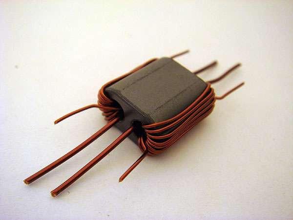
15 Photo of the G11 board after installation of both channel filters. Attach 4 wire ribbon cable between 4 pin connectors J6U and J2S. Test the filter switching of relays RL1B and RL2B by changing the band in GSDR. SWR bridge T1S Wind and install SWR bridge transformer T1S Binocular core, BN c-c1: Enamel wire 0.5mm 10 turns d-d1: Enamel wire 0.5mm 10 turns a-a1: Enamel wire, 0.8mm 1 turn b-b1: Enamel wire, 0.8mm 1 turn NOTE: Strip and tin leads properly before soldering onto the board. Photos below show bridge after winding and installation on PCB.
16


17 To check proper functionality of the SWR bridge - Install temporary wire as per photo - Connect receiving antenna to ANT connector to the right, J1S - NOTE: Since the receiving signal is passed via RXant, RX2 must still be selected in the GSDR software If the SWR bridge transformer T1S is installed properly, there will be no noticeable difference in signal strength when the antenna is connected to J1S. Total measurable BP / LP filter loss with calibrated signal generator is 1-2dB.


18 G11 Connation and cabling 1 USB port Connect to PC 2 PTT out Linear amp keying 3 PTT/Hand key Hand key or PTT 4 Paddle To paddle / keyer, also boot / firmware write 5 RX2 Second receiver input or transverter IN/OUT 6 RX1 Main antenna connector 7 DC input To 13.5V power supply 8 Line in Connect to sound card LINE IN *must be STEREO
19 9 MIC Out Microphone 10 MIC In Microphone 11 FM Line Out Connect to sound card LINE OUT 12 Phones To head phones *Receiver-only connections highlighted This completes the assembly of G11 receiver. NOTE: Before proceeding to Part 2 of the assembly (transmitter) please take as much time as possible to get familiar with the GSDR software. Performance of any software defined radio is directly related to the quality of sound card installed. Find out how various sound card settings (latency, sampling rate, drivers etc.) affect reception and performance. Adjust receiver image rejection [IR], set wide band image rejection [WBIR], calibrate S-meter level and frequency, install VAC and virtual ports and use your receiver to decode digital signals like WSPR, JT65, RTTY and others. Learn how to integrate GSDR/G11 with other amateur applications (contesting software, logbook etc). Keep in mind that G11 is high performance SDR transceiver! It will allow you to experience amateur radio communication form new perspective and it will broaden your horizons like no analog box radio. Join GenesisRadio Yahoo group to share your experience or ask questions if you need assistance,. Check the group s files for more help: Apendix 40m - 30m Filter [7-10 MHz] : For component values for this filter see following documents BP : filter No. 6 LP: filter No. 6 Practical realization: BP L6B=L7B=L 8B = 1.2uH 20 turns 0.5mm wire on a small yellow toroid LP L1B = 0.83 uh = 14 turns 0.8mm wire on a large diameter yellow toroid L2B = 0.60 uh = 12 turns 0.8mm wire on a large diameter yellow toroid
G11+ GSDR quick start assembly manual [Part 2]
![G11+ GSDR quick start assembly manual [Part 2]](/thumbs/94/119194661.jpg "G11+ GSDR quick start assembly manual [Part 2]") G11+ GSDR quick start assembly manual [Part 2] January 31, 2012 Ver 1.1 Tasa, YU1LM and Nick, VK2DX Overview G11 quick start assembly manual Part 2 covers assembly of the TX components. There are two chapters
G11+ GSDR quick start assembly manual [Part 2] January 31, 2012 Ver 1.1 Tasa, YU1LM and Nick, VK2DX Overview G11 quick start assembly manual Part 2 covers assembly of the TX components. There are two chapters
HT-1A Dual Band CW QRP Transceiver. Kit Building Instructions
 HT-A Dual Band CW QRP Transceiver Kit Building Instructions Rev B, July 8, 08 Designed by BD4RG Exclusively distributed by CRKITS.COM and its worldwide distributors Join the group http://groups.io/g/crkits
Kit for 20m 5W SDR transceiver for CW-SSB-Digital
 Kit for 20m 5W SDR transceiver for CW-SSB-Digital Keep up with the times keep up - ICOM have already recognized this technology and created its first SDR transceiver IC-7300 but the price. Start study
DEM Part Number L144-28INTCK 144 MHz Transverter Kit and complete kit
 DEM Part Number L144-28INTCK 144 MHz Transverter Kit and complete kit Power Out: Noise Figure and Gain: DC Power Requirement: 50 mw linear minimum 3.5 db NF nominal, 5 dbg maximum 12-15.5 VDC, 13.8 nominal
12kHz LIF Converter V2.43 9Mhz version
 12kHz LIF Converter V2.43 9Mhz version Please Note: This document supersedes all previously released documents and drawings on the LIF subject. This is the latest and most up-to-date document at this time.
Read This Page First
 Read This Page First If you are reading this you know the manuals are always available at QRPKITS.com. This is version 8.0 of the manual dated 4/27/2016. There is no need to print out the whole assembly
Construction Guide of TH300S
 Construction Guide of TH300S TH300S is a 2-band SSB/CW transceiver, used with DDS as LO, and features dual operation system ham band and general coverage band. A doubly balanced diode ring mixer is used
SoftRock v6.0 Builder s Notes. April 6, 2006
 SoftRock v6.0 Builder s Notes April 6, 006 Be sure to use a grounded tip soldering iron in building the v6.0 SoftRock circuit board. The soldering iron needs to have a small tip, (0.05-0. inch diameter),
SoftRock v6.0 Builder s Notes. May 22, 2006
 SoftRock v6.0 Builder s Notes May 22, 2006 Be sure to use a grounded tip soldering iron in building the v6.0 SoftRock circuit board. The soldering iron needs to have a small tip, (0.05-0.1 inch diameter),
Elecraft EC1 Design Contest Entry
 Elecraft EC1 Design Contest Entry The following is an Elecraft EC1 design contest entry from Joe Loritz, N9ZIA. Design Overview This design is a low cost, easy to homebrew, 100-900 MHz antenna analyzer.
HAMTRONICS TB901 FM EXCITER INSTALLATION, OPERATION, & MAINTENANCE
 HAMTRONICS TB901 FM EXCITER INSTALLATION, OPERATION, & MAINTENANCE GENERAL INFORMATION. The TB901 is a single-channel low power fm transmitter (exciter) designed to provide 300-600 milliwatts continuous
Dual Band Filter Assembly Manual
 Dual Band Filter Assembly Manual 12 January 2018 Rev D Version Theory of Operation: The purpose of a Bandpass Filter is to filter out or reject all unwanted signals. The original KN-Q7A Receive Filter
Hendricks QRP Kits The Twofer Rev
 Hendricks QRP Kits The Twofer Rev 1 11-15-06 1. Description The Twofer is a classic QRP transmitter that s easy to assemble and operate. It uses a JFET VXO (variable crystal oscillator), driver stage and
HF Amateur SSB Receiver
 HF Amateur SSB Receiver PCB Set for radio club project http://rhelectronics.net PCB for DIY HF Amateur SSB Receiver 20M The receiver is a simple syperheterodyne type with quartz crystal filter. The circuit
SPECIFICATIONS: Subcarrier Frequency 5.5MHz adjustable, FM Modulated +/- 50KHz. 2nd 11MHz >40dB down from 5.5MHz
 Mini-kits AUDIO / SUBCARRIER KIT EME75 Version4 SPECIFICATIONS: Subcarrier Frequency 5.5MHz adjustable, FM Modulated +/- 50KHz Subcarrier Output 1.5v p-p Output @ 5.5MHz DESCRIPTION & FEATURES: The Notes
NEW DESIGN***DEM Part Number FRS***NEW DESIGN Low power 144 MHz Transverter for the Flex Radio System SDR-1000 Operating Specifications:
 NEW DESIGN***DEM Part Number 144-28FRS***NEW DESIGN Low power 144 MHz Transverter for the Flex Radio System SDR-1000 Operating Specifications: Operating Voltage: 12.0-15.5 VDC, 13.8 nominal Current Drain:
Blue Point Engineering Inc.
 Engineering Inc. ireless Radio Control of Puppets Setup Overview RF Control C Pointing the ay to Solutions! Hardware Setup Overview Page 1 Servo No.1 Servo No.2 Control Signal Line RX8ch1,2 Servo Board
N3ZI Kits General Coverage Receiver, Assembly & Operations Manual (For Jun 2011 PCB ) Version 3.33, Jan 2012
 Version 3.33, Jan 2012") N3ZI Kits General Coverage Receiver, Assembly & Operations Manual (For Jun 2011 PCB ) Version 3.33, Jan 2012 Thank you for purchasing my general coverage receiver kit. You can use the photo above as a
N3ZI Kits General Coverage Receiver, Assembly & Operations Manual (For Jun 2011 PCB ) Version 3.33, Jan 2012 Thank you for purchasing my general coverage receiver kit. You can use the photo above as a
Development of the QSX transceiver kit
 Development of the QSX transceiver kit Norfolk Amateur Radio Club Wednesday 9-Jan-2019 Hans Summers, G0UPL http://qrp-labs.com QCX 5W CW transceiver kit QRP Labs CW Xcvr Introduced at YOTA 2017 summercamp
Beta-test ED1 PCB installed in I0CG s K1
 K1 SSB Modification (Ed.2) This description provides the receiver (RX) modifications, assembly, alignment and operation as a first step. In a second step you can add the remaining transmitter (TX) modifications,
Construction Manual 4m-Linear-Transverter XV4-15
 Construction Manual 4m-Linear-Transverter XV4-15 Holger Eckardt DF2FQ Kirchstockacherstr. 33 D-85662 Hohenbrunn 3207 Technical data exciter frequency: 21.0... 21.5 MHz RF frequency: 70.0.. 70.5 MHz supply
BP-1A. Band-Pass variable filter continuous tuning from 3 to 30MHz. For analogue or software-defined receivers (SDR) Assembly manual
 Assembly manual") BP-1A Band-Pass variable filter continuous tuning from 3 to 30MHz. For analogue or software-defined receivers (SDR) Assembly manual Last updated: December 1, 2017 ea3gcy@gmail.com Updates and news at:
BP-1A Band-Pass variable filter continuous tuning from 3 to 30MHz. For analogue or software-defined receivers (SDR) Assembly manual Last updated: December 1, 2017 ea3gcy@gmail.com Updates and news at:
"Nighthawk" CW Transceiver Kit V3.1
 "Nighthawk" CW Transceiver Kit V3.1 Brief Introduction The "Nighthawk" CW transceiver is based on a well-known US design by Dave Benson, K1SWL at Small Wonder Labs. Its classic design includes a standard
SoftRock v5.0 Builder s Notes. December 12, Building a QSD Kit
 SoftRock v5.0 Builder s Notes December 12, 2005 Building a QSD Kit Be sure to use a grounded tip soldering iron in building the QSD board. The soldering iron needs to have a small tip, (0.05-0.1 inch diameter),
Connecting the FCC-2 to the Hendricks DC Kits Bob Okas, W3CD
 Connecting the FCC-2 to the Hendricks DC Kits Bob Okas, W3CD This is an application note that describes how you can connect the NorCal FCC-1/2 combination to the DC kits. It involves a few extra components
S Pixie QRP Kit User Manual. Welcome to visit the home page to obtain the latest data. 1 / 24. Revision V160515
 S-Pixie QRP Kit User Manual Revision V160515 Welcome to visit the home page www.lxqqfy.com to obtain the latest data. 1 / 24 1. Introduction PIXIE is a very small volume of simple 40 meter band micro-power
FC3 Project Info: PIC18F /500MHZ Frequency Counter & RF Meter. This project is developed for Amateur Radio Community by:
 Fox Delta Amateur Radio Projects & Kits FC3-0915 FC3 Project Info: PIC18F4550 50/500MHZ Frequency Counter & RF Meter This project is developed for Amateur Radio Community by: Antonio Alfinito / I2TZK Dinesh
Ameritron ALS-600 Retrofit ALS-600-LPF Assembly Manual
 Ameritron ALS-600 Retrofit ALS-600-LPF Assembly Manual FEATURES Automatic band change based on TX frequency. PIN diode QSK RX/TX switch. Temperature controlled FAN for quiet operation. RS-232 serial port
QRPGuys Michigan Mighty Might Plus 40M Transmitter
 QRPGuys Michigan Mighty Might Plus 40M Transmitter First, familiarize yourself with the parts and check for all the components. If a part is missing, please contact us and we will send one. You must use
Construction Manual 6m-Linear-Transverter XV6/10
 Construction Manual 6m-Linear-Transverter XV6/10 Holger Eckardt DF2FQ Kirchstockacherstr. 33 D-85662 Hohenbrunn 2606 Technical data exciter frequency: 28... 30 MHz RF frequency: 50... 52 MHz supply voltage:
About LC Meter This is one of the most accurate and simplest LC inductance / capacitance Meters that one can find, yet one that you can easily build y
 Home Electronic Store Electronic Blog Electronic Schematics Tutorials Downloads Lin Very Accurate LC Meter based on PIC16F84A IC. LC Meter Part's List: 2x 1K 2x 6.8K 1x 47K 3x 100K 1x 10K POT 2x 10pF 1x
WA3RNC 30 METER CRYSTALPLEXER TRANSMITTER KIT ASSEMBLY INSTRUCTIONS
 WA3RNC 30 METER CRYSTALPLEXER TRANSMITTER KIT ASSEMBLY INSTRUCTIONS Description The WA3RNC 30 Meter Crystalplexer is a low power crystal controlled QRP transmitter offering a significantly improved tuning
Building and Operating: LF Converter An SA612 based LF up-converter from Jackson Harbor Press
 Introduction: Building and Operating: LF Converter An SA612 based LF up-converter from Jackson Harbor Press The frequencies below the broadcast band are covered by few receivers on the market - those that
Welcome to Ham Radio 201 New General / Extra Session
 Welcome to Ham Radio 201 New General / Extra Session Sponsored by Agenda New Technician / New Licensee 8:00 Kickoff 8:15 VHF/UHF Gear - George 9:00 VHF/UHF Operating - Beric 9:45 VHF Digital Voice George
Build this Direct Digital Synthesizer "Development Kit" By: Diz Gentzow, W8DIZ
 Build this Direct Digital Synthesizer "Development Kit" By: Diz Gentzow, W8DIZ A great tutorial for adding a keypad to the DDS Kit by Bruce, W8BH This manual has been prepared to be read directly on screen.
ALX-SSB 5 Band Filter Assembly Manual 19 November 2018
 ALX-SSB 5 Band Filter Assembly Manual 19 November 2018 Contents Theory of Operation:... 1 Figure 1... 2 Parts Included:... 4 Board Overview:... 5 Figure 2... 5 Figure 3... 5 Board Assembly:... 6 Cable
INSTALLATION AND CONNECTIONS Section 2
 STLLTION ND CONNECTIONS Section Unpacking - ntenna jumper cable connection - Selecting a location - Rack mounting handle attachment - Grounding -3 ntenna connection -3 CF (Compact Flash) memory card -3
A NEW LIFE FOR THE FT-290R TRANSCEIVER! By F5RCT
 A NEW LIFE FOR THE FT-290R TRANSCEIVER! By F5RCT The FT290R is an old amateur radio workhorse which was a very popular transceiver during the 80 s. It is a 2metre multimode portable which can run with
V6.2 SoftRock Lite Builder s Notes. November 17, 2006
 V6.2 SoftRock Lite Builder s Notes November 17, 2006 Be sure to use a grounded tip soldering iron in building the v6.2 SoftRock circuit board. The soldering iron needs to have a small tip, (0.05-0.1 inch
Modifying an IC735 for the 630m band 2014 Jacek Lipkowski SQ5BPF
 Modifying an IC735 for the 630m band 2014 Jacek Lipkowski SQ5BPF The IC735 is a very versatile transceiver, which can be obtained for a good price and is easy to modify and fix.
Assembly Manual V1R2B-Rev1.0D
 Assembly Manual V1R2B-Rev1.0D for 4 State QRP MagicBox - Solid State Transmit/Receive System Designed by: Jim Kortge, K8IQY Copyright 2009-2012 - All rights reserved This system is the result of some brainstorming
MFJ-1048 PASSIVE PRESELECTOR. Introduction. Installation
 Introduction MFJ-1048 PASSIVE PRESELECTOR The MFJ-1048 is designed to reduce receive overload from strong out of band signals. It contains selective circuits that cover 1.6 to 33 MHz in six steps, providing
FM Audio/Squelch Board by Steve Dold, W6KCS w6kcs (at) stevedold (dot) com
 stevedold (dot) com") FM Audio/Squelch Board by Steve Dold, W6KCS w6kcs at stevedold dot com Board hardware version 7-8 Firmware version 7.x This board connects to an FM receiver's discriminator/detector and provides squelched,
FM Audio/Squelch Board by Steve Dold, W6KCS w6kcs at stevedold dot com Board hardware version 7-8 Firmware version 7.x This board connects to an FM receiver's discriminator/detector and provides squelched,
FT-897 Alignment. Local Oscillator Adjustment. PLL Adjustment
 FT-897 Local Oscillator Adjustment Reference Frequency Adjustment a. Connect a frequency counter to TP1032. b. Adjust the trimmer capacitor (TC5001) for 67.875000MHz ±5Hz on the frequency counter. c. Connect
HAMTRONICS R901 FM RECEIVER INSTALLATION, OPERATION, AND MAINTENANCE INSTRUCTIONS
 HAMTRONICS R901 FM RECEIVER INSTALLATION, OPERATION, AND MAINTENANCE INSTRUCTIONS GENERAL INFORMATION. The R901 is a commercial grade single-channel fm receiver for the 902-928 MHz amateur band and the
S-Pixie QRP Kit. Student Manual. Revision V 1-0
 S-Pixie QRP Kit Student Manual Revision V 1-0 Introduction The Pixie 2 is a small, versatile radio transceiver that is very popular with QRP (low power) amateur radio operators the world over. It reflects
GRAND STRAND AMATEUR RADIO CLUB
 The GRAND STRAND AMATEUR RADIO CLUB (GSARC) Myrtle Beach SC is offering used amateur related equipment for sale. Written bids may be submitted to the GSARC up to Friday, November 23 rd, 2018. Only currently
KN-Q10 Assembly Manual
 KN-Q10 Assembly Manual Translated by Adam Rong, BD6CR/4 with permission from Ke Shi, BA6BF Edited by Stephen, VK2RH Revision B, Oct 14, 2010 Thank you for purchasing the KN-Q10 4 Band SSB/CW Dual Mode
S-RockMite QRP Kit User Manual. Welcome to visit the home page to obtain the latest data. 1 / 23. Revision V161101
 S-RockMite QRP Kit User Manual Revision V161101 Welcome to visit the home page www.lxqqfy.com to obtain the latest data. 1 / 23 1. Introduction This is a very small volume of simple 40 meter band micro-power
Easy Transmitter. Support ETX_REV5_Manual V2.7 Revised
 Easy Transmitter Introduction The Easy Transmitter kit from qrpkits.com provides a basic, crystal controlled transmitter with VXO tuning to provide a small tuning range around the crystal frequency. It
Basic Transceiver tests with the 8800S
 The most important thing we build is trust ADVANCED ELECTRONIC SOLUTIONS AVIATION SERVICES COMMUNICATIONS AND CONNECTIVITY MISSION SYSTEMS Basic Transceiver tests with the 8800S Basic Interconnects Interconnect
Cubic Astro 103 Restoration Notes
 Cubic Astro 103 Restoration Notes W7CPA February 2016 I restored a Cubic Astro 103 a few years ago and have enjoyed operating it for years. It s a very nice geezer wireless and the last amateur radio product
DC Injector (Bias Tee) kit. Technical Manual
 kit. Technical Manual") DC Injector (Bias Tee) kit Technical Manual Document Author Dave Powis, G4HUP Date 7 Jan 2017 Version Issue 2_0 Document Ref HUP-05-020 http://huprf.com Tel +44 (0)1473 737717 g4hup@outlook.com Contents
DC Injector (Bias Tee) kit Technical Manual Document Author Dave Powis, G4HUP Date 7 Jan 2017 Version Issue 2_0 Document Ref HUP-05-020 http://huprf.com Tel +44 (0)1473 737717 g4hup@outlook.com Contents
BAND DECODER and CONTROLLE R. Accessibility Upgrade and Operating Instructions
 ELE CRAFT KRC2 BAND DECODER and CONTROLLE R Accessibility Upgrade and Operating Instructions Revision A, March 4, 2004. Copyright 2004, Elecraft; All Rights Reserved Introduction The KRC2 Accessibility
TS-590SG HF/ 50MHz All-Mode TRANSCEIVER_
 New Product Release Information Oct 2014 TS-590SG HF/ 50MHz All-Mode TRANSCEIVER_ Kenwood introduces Updated to new G version new HF/50MHz All-Mode Transceiver Four years ago we launched our best-selling
HAMTRONICS TA451 UHF FM TRANSMITTER ASSEMBLY, OPERATION, & MAINTENANCE
 HAMTRONICS TA451 UHF FM TRANSMITTER ASSEMBLY, OPERATION, & MAINTENANCE GENERAL INFORMATION. The TA451 is a single-channel uhf fm transmitter designed to provide 2 to 2½ Watts output (continuous duty) into
Bitx Version 3 Linear Amplifier Assembly
 Bitx Version 3 Linear Amplifier Assembly The power supply section has 2 options. 1 - AC input and a higher voltage on the IRF510 and +12 volts to the bitx. 2 - +12 volts applied to both the final and the
HAMTRONICS R451 UHF FM RECEIVER: INSTALLATION, OPERATION, & MAINTENANCE
 HAMTRONICS R451 UHF FM RECEIVER: INSTALLATION, OPERATION, & MAINTENANCE FUNCTIONAL DESCRIPTION. The R451 is a premium, commercial- grade single-channel uhf fm receiver. It features a GaAs FET rf amplifier
Step by Step Building PJ meter ARDF Receiver Kit. CRKITS.COM August 5, 2013
 Step by Step Building PJ-80 80-meter ARDF Receiver Kit CRKITS.COM August 5, 2013 What is ARDF? ARDF is the abbreviation of Amateur Radio Direction Finding, or so called Fox Hunting. If you are looking
TLN-428 Voltage Controlled State Variable Filter
 The Tellun Corporation TLN-428 Voltage Controlled State Variable Filter User Guide, Rev. 1.1 Scott Juskiw The Tellun Corporation scott@tellun.com TLN-428 User Guide Revision 1.1 March 16, 2003 Introduction
HAMTRONICS R144 VHF FM RECEIVER, REV. 4/94: INSTALLATION AND MAINTENANCE
 HAMTRONICS R144 VHF FM RECEIVER, REV. 4/94: INSTALLATION AND MAINTENANCE FUNCTIONAL DESCRIPTION. The R144 is a premium commercial grade single-channel vhf fm receiver. It features a helical resonator front
PC to Radio Audio and Key-line Interface
 PC to Radio Audio and Key-line Interface Background - This simple interface was developed to capacitive couple audio signals between a radio and PC, to provide a means of adjusting audio levels between
Good luck and enjoy your new radio.
 TM 5-Step SDR-1000 Quick Start Guide Installation and The purpose of this guide is to get you on the air as quickly as possible so you can begin to enjoy your new SDR-1000. This document is not a substitute
Building a Bitx20 Version 3
 Building a Bitx20 Version 3 The board can be broken into sections and then built and tested one section at a time. This will make troubleshooting easier as any problems will be confined to one small section.
Read This Page First
 Pacific Antenna 0 Watt HF Amplifier Kit Manual This is Version 5.5 dated 060505 Read This Page First If you are reading this you know the manuals are always available at QRPKITS.com. If you have questions
The ROSE 80 CW Transceiver (Part 1 of 3)
") Build a 5 watt, 80 meter QRP CW Transceiver!!! Page 1 of 10 The ROSE 80 CW Transceiver (Part 1 of 3) Build a 5 watt, 80 meter QRP CW Transceiver!!! (Designed by N1HFX) A great deal of interest has been
Build a 5 watt, 80 meter QRP CW Transceiver!!! Page 1 of 10 The ROSE 80 CW Transceiver (Part 1 of 3) Build a 5 watt, 80 meter QRP CW Transceiver!!! (Designed by N1HFX) A great deal of interest has been
Cross-Connect Interface
 Cross-Connect Interface User Manual Document #: 050-015-0036R01 November 2006 TASC Systems Inc. Langley, BC Canada Cross-Connect System User Manual Preface This document describes the installation, commissioning
S Forty 9er QRP Kit User Manual. Welcome to visit the home page to obtain the latest data. 1 / 23. Revision V160604
 S-Forty-9er QRP Kit User Manual Revision V60604 Welcome to visit the home page www.lxqqfy.com to obtain the latest data. / 3 . Introduction This is a very small volume of simple 40 meter band micro-power
Pacific Antenna - Easy TR Switch
 Pacific Antenna - Easy TR Switch Kit Description The Easy TR Switch is an RF sensing switch that can be used to switch an antenna between a receiver and transmitter. It also has a second switched pair
QRPme.com Kits. Tx/Tuna Topper. Assembly and Operation Guide. Kits for the QRP and Electronics Hobbyist. Heatsink left off for better assembly viewing
 QRPme.com Kits Kits for the QRP and Electronics Hobbyist Tx/Tuna Topper Heatsink left off for better assembly viewing QRMme.com Kits Tx/Tuna Topper Contents Figures and Illustrations...............................
Pacific Antenna Low Pass Filter Kit
 Pacific Antenna Low Pass Filter Kit Description Many basic transmitter and/or transceiver designs have minimal filtering on their output and frequently have significant harmonic content in their signals.
Read This Page First
 Read This Page First If you are reading this you know the manuals are always available at QRPKITS.com. If you have questions contact qrpkits.com@gmail.com There is no need to print out the whole assembly
SkyPI. Order SkyPi at
 -CW, RTTY, WSPR, Open Source -SDR with No PC Required -40, 30, 20, 17, and 15 Meter Versions SkyPi is ideal for QRP enthusiasts and experimenters who want a modern and versatile software radio created
Delta 44 Quick Start Guide
 Delta 44 Quick Start Guide The M-Audio Delta 44 is a high grade professional sound card. When setup properly for use with the SDR- 1000, the results speak for themselves. Unbelievably high dynamic range
Goals: Board ID's in System Transmitter components/modules TLD5321A exciter board
 Micor Unified Chassis Base Station Conversion to A Ham Band Repeater by Lawrence Glaister VE7IT November 2002 Goals: -To duplex a base station radio set for repeater usage. - To mount and tune a micor
200GTL ALIGNMENT REVISION: 1.0 BURKE MODEL: 200GTL REVISION: 1.2 DATE: 02/14/06. Total Pages: 6 pages. Page:1 print date: 9/23/09
 ALIGNMENT PROCEDURE MODEL: 200GTL REVISION: 1.2 DATE: 02/14/06 PREPARED BY: BURKE Total Pages: 6 pages Page:1 print date: 9/23/09 1 TEST CONDITION: 200GTL ALIGNMENT INSTRUCTION 1.0. TEST TEMPERTAURE: 77
Fox Delta FC Amateur Radio Projects & Kits. FC3 Project Info: PIC18F /500MHZ Frequency Counter & RF Meter
 Fox Delta Amateur Radio Projects & Kits FC3-0812 FC3 Project Info: PIC18F4550 50/500MHZ Frequency Counter & RF Meter This project is developed for Amateur Radio Community by: Antonio Alfinito / I2TZK Dinesh
Cricket 80a Assembly Manual v Copyright David Cripe NM0S The 4 State QRP Group
 Cricket 80a Assembly Manual v. 1.0 Copyright 2017 David Cripe NM0S The 4 State QRP Group Introduction Thank you for purchasing a CRICKET 80a Transceiver. We hope you will enjoy building it and find it
LnR Precision, Inc. 107 East Central Avenue, Asheboro, NC
 LD5 CW/SSB QRP Transceiver Quick guide manual Description: At the development base of the digital signal processing unit, an algorithm is embedded for IQ processing of the channels with phase suppression
CS Series SSB Transceiver
 CS Series SSB Transceiver Single Band SSB Transceiver Kit Manual Rev. Preliminary Release CRKITS.COM April 8, 2017 Preliminary Release Original written by Adam Rong, BD6CR/4 Modified by Larry Lovell, N7RGW
Technical Info Doc: Galileo2 A simple Direct Conversion Receiver for 20.1MHZ
 Fox Delta Amateur Radio Projects & Kits FD Galileo2 Technical Info Doc: Galileo2 A simple Direct Conversion Receiver for 20.1MHZ This Project is dedicated to our beloved scientist Galileo: Galileo was
: Hacking Bitx Version3B, C: : 20mt to 40mt band: PART I
 : Hacking Bitx Version3B, C: : 20mt to 40mt band: PART I Fig 1: Bitx Ver3C SBL-1 20 Conversion for Bitx40 The picture in Fig1 is a Bitx3C SBL-1 for 40mt band, constructed from the Bitx Version 3C SBL-1
Arizona ScQRPion QRP Club. Ft Tuthill w DC CW Transceiver for 80m Part 1 of 2. by Dan Tayloe, N7VE. Ft Tuthill Page 1 of 31
 Arizona ScQRPion QRP Club Ft Tuthill 80 2.5w DC CW Transceiver for 80m Part 1 of 2 by Dan Tayloe, N7VE Page 1 of 31 Table of Contents Specifications... 4 Specifications... 4 Receiver... 4 Transmitter...
Pacific Antenna Easy TR Switch
 Pacific Antenna Easy TR Switch Kit Description The Easy TR Switch is an RF sensing circuit with a double pole double throw relay that can be used to automatically switch an antenna between a separate receiver
LD5 CW/SSB QRP Transceiver SDR /DSP
 LD5 CW/SSB QRP Transceiver SDR /DSP Quick guide manual Description: At the development base of the digital signal processing unit, an algorithm is embedded for IQ processing of the channels with phase
QRPme.com Kits. Tx/Tuna Topper. Assembly and Operation Guide. Kits for the QRP and Electronics Hobbyist. Heatsink left off for better assembly viewing
 QRPme.com Kits Kits for the QRP and Electronics Hobbyist Tx/Tuna Topper Heatsink left off for better assembly viewing Contents Figures and Illustrations............................... 3 Jumpers............................................
DEM TC DEM TRANSVERTER CONTROL
 DEM TC DEM TRANSVERTER CONTROL The DEM Transverter Control (DEM TC) is the circuit board that controls all transverter functions in the DEMI 2.3 GHz. -10 GHz. transverters. It was designed with many options
S WAMING QRP Kit User Manual. Welcome to visit the home page to obtain the latest data. 1 / 23. Revision 2.1
 S-WAMING QRP Kit User Manual Revision 2.1 Welcome to visit the home page www.lxqqfy.com to obtain the latest data. 1 / 23 1. Introduction This is a very small volume of simple 40 meter band micro-power
QRPme.com Kits. Tx/Tuna Topper. Assembly and Operation Guide. Kits for the QRP and Electronics Hobbyist. Heatsink left off for better assembly viewing
 QRPme.com Kits Kits for the QRP and Electronics Hobbyist Tx/Tuna Topper Heatsink left off for better assembly viewing Contents Figures and Illustrations............................... 3 Jumpers............................................
Tuna Tunah. Switched Inductor Antenna Tuner. Builder's Guide by Kevin Gilot NZ1I & Rex Harper W1REX. version 1.2
 Tuna Tunah Switched Inductor Antenna Tuner Builder's Guide by Kevin Gilot NZ1I & Rex Harper W1REX version 1.2 Tuna Tunah List of Materials Qty Description PCB Location ( ) 1-.22uH Inductor (Red-Red-Silver).22
Assembly Instructions for the 1.5 Watt Amplifier Kit
 Assembly Instructions for the 1.5 Watt Amplifier Kit 1.) All of the small parts are attached to a sheet of paper indicating both their value and id. 2.) Leave the parts affixed to the paper until you are
Low Cost Intermediate 144 MHz Transverter Kit DEM Part Number DC
 Low Cost Intermediate 144 MHz Transverter Kit DEM Part Number 144-28DC Operational Overview: The DEM 144-28DC is a low power, high performance 144 MHz to 28 MHz transmit and receive converter. It is intended
WJ-8617B and WJ-8618B HF Upgrades: 500 KHz to 1100 MHz By: Stephen Pappin
 WJ-8617B and WJ-8618B HF Upgrades: 500 KHz to 1100 MHz By: Stephen Pappin The typical frequency coverage for an 8617B or 8618B is from 20 MHz to 1100 MHz (500 MHz without FE). These versions have pre selectors
Hendricks QRP Kits BITX20A to BITX17A Conversion Instructions
 Hendricks QRP Kits BITX20A to BITX17A Conversion Instructions 30 November 2008 Converting your BITX20A Kit to a BITX17A Kit is not all that complex. It only requires that you change crystals and some resonance
Stand Alone VXO (SAVXO) Assembly Manual Manual Version 1.0B_
 Assembly Manual Manual Version 1.0B_") Stand Alone VXO (SAVXO) Assembly Manual Manual Version.0B_0-6-0 Designed by: Jim Kortge, K8IQY Kitted & Sold by: 4 State QRP Group Copyright: 0 Forward Thank you for purchasing a 4 State QRP Group Stand
Stand Alone VXO (SAVXO) Assembly Manual Manual Version.0B_0-6-0 Designed by: Jim Kortge, K8IQY Kitted & Sold by: 4 State QRP Group Copyright: 0 Forward Thank you for purchasing a 4 State QRP Group Stand
Yana Dongles Tom Berger K1TRB (c)2016 v171227
2016 v171227") Yana Dongles Tom Berger K1TRB (c)2016 v171227 These notes elaborate some items described in the Build notes, and add some more dongles enhancing Yana. Every effort has been exerted to save on the cost
Yana Dongles Tom Berger K1TRB (c)2016 v171227 These notes elaborate some items described in the Build notes, and add some more dongles enhancing Yana. Every effort has been exerted to save on the cost
Assembly Instructions for the FRB FET FM 70 Watt Amp
 Assembly Instructions for the FRB FET FM 70 Watt Amp 1.) Orient the circuit board with the diagram 2.) Use a narrow chisel tip 25-30 watt soldering iron for assembly 3.) All the small parts are taped onto
Spectrian 2304 MHz SSPA. Garry C. Hess, K3SIW June 11, 2004
 Spectrian 2304 MHz SSPA Garry C. Hess, K3SIW June 11, 2004 A solid-state power amplifier (SSPA) manufactured by Spectrian can produce on the order of 200 W linear output 1 at 2304 MHz with little modification.
CW-ADD. Universal CW Adapter for SSB Transceivers. Assembly manual. Last updated: October 1,
 CW-ADD Universal CW Adapter for SSB Transceivers Assembly manual Last updated: October 1, 2017 ea3gcy@gmail.com Updates and news at: www.ea3gcy.com Thanks for building the Universal CW Adapter kit CW-ADD
K1EL 75 Meter AM Phone Receiver AMR75
 Features 3.8MHz Amateur Phone Band Receiver 100 KHz Tuning Range Wideband Hi-Fi AM mode reception Single Sideband mode with on board BFO Uses single chip TRF TA7642 IC Low impedance 8 ohm speaker output