S Pixie QRP Kit User Manual. Welcome to visit the home page to obtain the latest data. 1 / 24. Revision V160515
|
|
|
- Tabitha Cannon
- 6 years ago
- Views:
Transcription

1 S-Pixie QRP Kit User Manual Revision V Welcome to visit the home page to obtain the latest data. 1 / 24
2 1. Introduction PIXIE is a very small volume of simple 40 meter band micro-power amplitude telegraph transceiver, Despite it's small size and DC receiver limitations, it is capable of working several hundred miles when connected to a good 40 meter antenna. "S-Forty-9er", Designed by LXQQFY.com,. Improvements are as follows: The vertical resistance is changed to horizontal resistance, Solves the problem of resistance to short circuit. We do not distinguish between positive and negative electrodes of power supply. Power input range increased to 13.8V. Add the buzzer sounds for send (use jumper shield), Add led signal for send. Add acrylic shell. 2. Specifications Power supply: 9~13.8V Volts DC, >500mA (Recommend the use of batteries) Antenna: 50ohm,7MHz,SWR<2.0 Receive: static current 20mA Transmission power: 1.2W Frequency: launch the vibration frequency,7023 KHZ Receives the local oscillator frequency: about KHZ work mode: the CW KEY: Manual Case: Acrylic 2 / 24
3 3. Circuit principle See the last page of the document accompanying drawings, 9018 and surrounding components constituting a typical Colpitts oscillator and keeps oscillating (the oscillation signal leaks around 1mW) when receiving the local oscillator signal is directly coupled through a capacitor to Emission state (the key is pressed), 8050 as a class C amplifier, the amplified signal via 0.01uF capacitor coupled to a pi-type low-pass filter, and then sent to the antenna; reception state (key release), 9018 element around the beat oscillator (BFO), 1N4001 coupled with high voltage and reduce capacitive pressure is increased with the ends of the DC, the local oscillation frequency can be increased to approximately 0-3KHz 7.023MHz reception signal can be easily carried out bats frequency is biased in the non-linear region (think transistor is nothing more than two back-to-back second diode incorrect), the signal received by the antenna with the BFO signal mixer, mixing the audio signal obtained after the 0.1uF capacitor coupling posed to the LM386 audio power amplifier, the audio signal amplified by the 10uF capacitor across the LM386 5 feet straight evacuation headphones. The key control not only the LM386-off of the power supply is switched 1N4001 varactor bias, so that the capacity of the type of state change. 3 / 24

4 4. Production process 4.1 According to the list of components, check the number of components. Have tools, Electric iron, Solder wire, and A multimeter on hand. Take welding from low to high order, Recommend: Resistance -> Diode -> Capacitance -> Triode -> Crystal oscillator -> Bridge rectifier -> Electrolytic capacitor -> Ic -> Inductor -> LED -> Other. 4 / 24
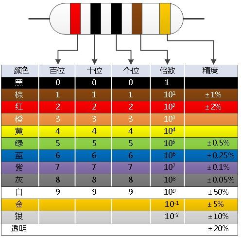
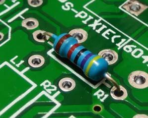
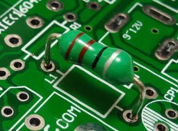
5 4.2 Resistance. 5 / 24


6 4.3 Diode. 1N4001 1N Capacitance. 104: 0.1uF 103: 10nF 101: 100pF 471: 470pF 473: 47nF 6 / 24


7 4.5 Triode and FET. 4.6 Crystal oscillator. 7 / 24


8 4.7 Bridge rectifier. 4.8 Electrolytic capacitor. 8 / 24

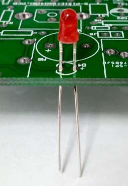
9 4.9 Ic Inductance LED. 9 / 24


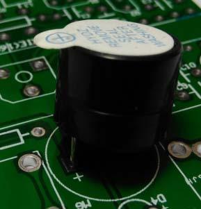
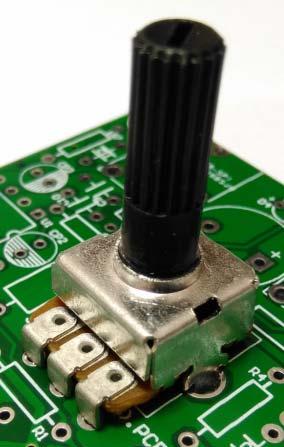
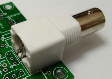
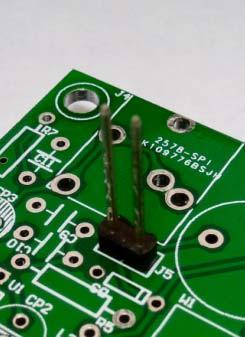
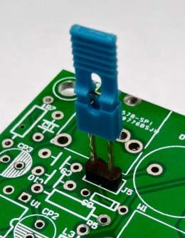
10 4.12 Other. DC Jack 3.5mm Socket(Key and Phone) Buzzer Variable resistor Q9(BNC) Pin Jumper Cap 10 / 24


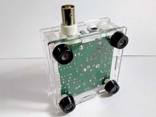
11 4.13 Install the acrylic case. 11 / 24


12 5. Debug 5.1 The power before installation of dummy load. Method 1: Method 2: Method 3: 12 / 24
13 5.2 Power on: Do not distinguish between positive electrode and negative electrode(internal rectification), Recommend the use of 12V DC battery, Can also use the 12V DC linear voltage stabilized power supply. If power on after tens of seconds without abnormal heating,then it's normal. 5.3 Listen to the base noise: Connect the 8ohm headset, after power will hear a slight voice, then it's normal. 5.4 The receiving circuit test: If connect the antenna to hear the voice and do not connect the antenna to hear the voice of a great difference,then it's normal. 5.5 The sending circuit test: Connect dummy load, connect the key, and power on. Now you can use the key control to send, Static current:20ma,sending current:120ma, In the sending state under the virtual load will be fever. Note: it is not a long time to send. 13 / 24

14 6. Usage method 6.1 Function diagram 14 / 24

15 6.2 Key. 6.3 Using the most common 8ohm headset. 15 / 24
16 6.4 The antenna is the key of the shortwave station, Requirements: frequency 7MHz, impedance 50ohm, SWR <1.5. Recommend the following: GP Antenna. Red: Radio; Bule:: Feeder(50ohm); Violet: Fishing rod(9 meters); Yellow: Dummy grounds(9 meters); Pink:: Oscillator(10.1 meters); 16 / 24
17 6.3.1 Windom Antenna. Winton antenna can be good to work in the three 40m/20m/10m band, the use of 1:4 Balun, according to the actual environment can have a variety of different installation methods. 17 / 24
18 6.3.1 DP Antenna. The DP antenna is adopted skywave communication,long distance communication effect is very good,the use to 1:1 balun, usually V installation. 18 / 24


19 7 Configuration. There are a variety of configurations, this paper shows the highest configuration 7.1 The 2.54 connector, no buzzer, no LED, small Variable resistor, no Acrylic. 19 / 24


20 7.2 The 2.54 connector, buzzer, LED, small Variable resistor, no Acrylic. 20 / 24


21 7.3 Q9(BNC), no buzzer, no LED, small Variable resistor, no Acrylic. 21 / 24

22 7.4 Q9(BNC), buzzer, LED, small Variable resistor, no Acrylic. 22 / 24


23 7.5 Q9(BNC), buzzer, LED, big Variable resistor, Acrylic. 23 / 24
24 8 List of components 1/4W Resistor Capacitor R7 10 ohm C1 C10 0.1uF(104) R4 470 ohm C2 C4 C8 C11 10nF(103) R3 1K C3 C7 100pF(101) R5 R8 10K C5 C6 470pF(471) R2 33K C9 47nF (473) R1 47K Inductance R6 100K L1 22uH(Color ring inductance) Electrolytic capacitor L2 1uH(Color ring inductance) CP1 100uF/16V L3 100uH (Color ring inductance) CP2 CP3 CP4 10uF/16V IC Transistor U1 LM386 D1 2W10(Bridge rectifier) Crystal oscillator D2 1N4001(Diode) Y MHz Q1 9018(Triode) Variable resistor Q2 8050(Triode) W1 47K(473) D3 1N4148(Diode) Other D4 LED J1 DC Jack J2 Q9(BNC) 51ohm 1W Resistor(for dummy load) J3 J4 3.5mm Socket(Key and Phone) PCB * 1 J5 Pin and Jumper Cap Acrylic case MG Buzzer 24 / 24
25
26 A B C D D C B A C1 0.1uF CP1 100uF/16V R3 1K R1 47K Q C3 100pF Y MHz D2 1N4001 C7 100pF R4 470 C4 10nF R2 33K L3 100uH C9 47nF Q L1 22uH R5 10K C2 10nF C5 470pF L2 1uH C6 470pF R6 100K C8 10nF D3 1N4148 CP4 10uF/16V C10 0.1uF BYP 7 GN 8 Vs 6 Vout 5 GN 1 -IN 2 +IN 3 GND 4 U1 LM386 CP2 10uF/16V R7 10 C11 10nF CP3 10uF/16V J3 KEY J4 PHONE J1 POWER J2 ANT J5 A - + MG VCC VCC R8 10K VCC D4 LED D1 2W10 W1 47K
S-RockMite QRP Kit User Manual. Welcome to visit the home page to obtain the latest data. 1 / 23. Revision V161101
 S-RockMite QRP Kit User Manual Revision V161101 Welcome to visit the home page www.lxqqfy.com to obtain the latest data. 1 / 23 1. Introduction This is a very small volume of simple 40 meter band micro-power
S Forty 9er QRP Kit User Manual. Welcome to visit the home page to obtain the latest data. 1 / 23. Revision V160604
 S-Forty-9er QRP Kit User Manual Revision V60604 Welcome to visit the home page www.lxqqfy.com to obtain the latest data. / 3 . Introduction This is a very small volume of simple 40 meter band micro-power
S WAMING QRP Kit User Manual. Welcome to visit the home page to obtain the latest data. 1 / 23. Revision 2.1
 S-WAMING QRP Kit User Manual Revision 2.1 Welcome to visit the home page www.lxqqfy.com to obtain the latest data. 1 / 23 1. Introduction This is a very small volume of simple 40 meter band micro-power
S-Pixie QRP Kit. Student Manual. Revision V 1-0
 S-Pixie QRP Kit Student Manual Revision V 1-0 Introduction The Pixie 2 is a small, versatile radio transceiver that is very popular with QRP (low power) amateur radio operators the world over. It reflects
RadiØKit Μ CW HAM RADIO TRANSCEIVER KIT. Assembly and operating manual
 RadiØKit-120 20Μ CW HAM RADIO TRANSCEIVER KIT Assembly and operating manual Boreiou Ipirou 78 Kolonos Athens- Greece - 10444 Tel: 210.5150527 210.5132673 www.freebytes.com Thank you for buying RadiØKit-1,
N3ZI Kits General Coverage Receiver, Assembly & Operations Manual (For Jun 2011 PCB ) Version 3.33, Jan 2012
 Version 3.33, Jan 2012") N3ZI Kits General Coverage Receiver, Assembly & Operations Manual (For Jun 2011 PCB ) Version 3.33, Jan 2012 Thank you for purchasing my general coverage receiver kit. You can use the photo above as a
N3ZI Kits General Coverage Receiver, Assembly & Operations Manual (For Jun 2011 PCB ) Version 3.33, Jan 2012 Thank you for purchasing my general coverage receiver kit. You can use the photo above as a
HT-1A Dual Band CW QRP Transceiver. Kit Building Instructions
 HT-A Dual Band CW QRP Transceiver Kit Building Instructions Rev B, July 8, 08 Designed by BD4RG Exclusively distributed by CRKITS.COM and its worldwide distributors Join the group http://groups.io/g/crkits
The ROSE 80 CW Transceiver (Part 1 of 3)
") Build a 5 watt, 80 meter QRP CW Transceiver!!! Page 1 of 10 The ROSE 80 CW Transceiver (Part 1 of 3) Build a 5 watt, 80 meter QRP CW Transceiver!!! (Designed by N1HFX) A great deal of interest has been
Build a 5 watt, 80 meter QRP CW Transceiver!!! Page 1 of 10 The ROSE 80 CW Transceiver (Part 1 of 3) Build a 5 watt, 80 meter QRP CW Transceiver!!! (Designed by N1HFX) A great deal of interest has been
1. What is the unit of electromotive force? (a) volt (b) ampere (c) watt (d) ohm. 2. The resonant frequency of a tuned (LRC) circuit is given by
 volt (b) ampere (c) watt (d) ohm. 2. The resonant frequency of a tuned (LRC) circuit is given by") Department of Examinations, Sri Lanka EXAMINATION FOR THE AMATEUR RADIO OPERATORS CERTIFICATE OF PROFICIENCY ISSUED BY THE DIRECTOR GENERAL OF TELECOMMUNICATIONS, SRI LANKA 2004 (NOVICE CLASS) Basic Electricity,
Department of Examinations, Sri Lanka EXAMINATION FOR THE AMATEUR RADIO OPERATORS CERTIFICATE OF PROFICIENCY ISSUED BY THE DIRECTOR GENERAL OF TELECOMMUNICATIONS, SRI LANKA 2004 (NOVICE CLASS) Basic Electricity,
Read This Page First
 Read This Page First If you are reading this you know the manuals are always available at QRPKITS.com. This is version 8.0 of the manual dated 4/27/2016. There is no need to print out the whole assembly
Bitx Version 3 Linear Amplifier Assembly
 Bitx Version 3 Linear Amplifier Assembly The power supply section has 2 options. 1 - AC input and a higher voltage on the IRF510 and +12 volts to the bitx. 2 - +12 volts applied to both the final and the
Building the Sawdust Regenerative Receiver
 Building the Sawdust Regenerative Receiver Introduction The Sawdust is a super regenerative receiver using the basic Armstrong design architecture. The receiver uses one toroidal transformer to provide
Analog RF Electronics Education at SDSMT: A Hands-On Method for Teaching Electrical Engineers
 Analog RF Electronics Education at : A Hands-On Method for Teaching Electrical Engineers Dr., Professor Department of Electrical and Computer Engineering South Dakota School of Mines and Technology (whites@sdsmt.edu)
Building the Sawdust Regenerative Receiver
 Building the Sawdust Regenerative Receiver Introduction The Sawdust is a super regenerative receiver using the basic Armstrong design architecture. The receiver uses one toroidal transformer to provide
HF Amateur SSB Receiver
 HF Amateur SSB Receiver PCB Set for radio club project http://rhelectronics.net PCB for DIY HF Amateur SSB Receiver 20M The receiver is a simple syperheterodyne type with quartz crystal filter. The circuit
Assembly Manual V1R2B-Rev1.0D
 Assembly Manual V1R2B-Rev1.0D for 4 State QRP MagicBox - Solid State Transmit/Receive System Designed by: Jim Kortge, K8IQY Copyright 2009-2012 - All rights reserved This system is the result of some brainstorming
V. 3. Assembly Guide. ShortWave Receiver Kit Double Super 10.7Mhz /455Khz SSB/CW/AM 5.9 Mhz to 8.1 Nominal. SW-Receiver
 Assembly Guide V. 3 JUNIOR 1 ShortWave Receiver Kit Double Super 10.7Mhz /455Khz SSB/CW/AM 5.9 Mhz to 8.1 Nominal SW-Receiver Table of contents PAGE TITLE PAGE JUNIOR 1 General Description I1 JUNIOR 1
1. PCB and schematic
 1. PCB and schematic 2. Assembly manual WHAT'S IN THE BOX 1 x PCB tape: o 5 x jumper o 6 x resistor 1K o 12 x resistor 10K o 1 x resistor 15K o 8 x resistor 100K o 2 x resistor 47K 4 x 14p IC socket 4
HAMTRONICS TB901 FM EXCITER INSTALLATION, OPERATION, & MAINTENANCE
 HAMTRONICS TB901 FM EXCITER INSTALLATION, OPERATION, & MAINTENANCE GENERAL INFORMATION. The TB901 is a single-channel low power fm transmitter (exciter) designed to provide 300-600 milliwatts continuous
Dual Band Filter Assembly Manual
 Dual Band Filter Assembly Manual 12 January 2018 Rev D Version Theory of Operation: The purpose of a Bandpass Filter is to filter out or reject all unwanted signals. The original KN-Q7A Receive Filter
About LC Meter This is one of the most accurate and simplest LC inductance / capacitance Meters that one can find, yet one that you can easily build y
 Home Electronic Store Electronic Blog Electronic Schematics Tutorials Downloads Lin Very Accurate LC Meter based on PIC16F84A IC. LC Meter Part's List: 2x 1K 2x 6.8K 1x 47K 3x 100K 1x 10K POT 2x 10pF 1x
ILER MK2. Appendices
 ILER MK2 QRP SSB Transceiver in Kit Form Appendices Last update: July 20, 2015 ea3gcy@gmail.com Most recent updates and news at: www.qsl.net/ea3gcy ILER-17 MK2 SSB QRP Transceiver Kit Page 1 APPENDIX 1:
Pacific Antenna Easy TR Switch
 Pacific Antenna Easy TR Switch Kit Description The Easy TR Switch is an RF sensing circuit with a double pole double throw relay that can be used to automatically switch an antenna between a separate receiver
Pacific Antenna - Easy TR Switch
 Pacific Antenna - Easy TR Switch Kit Description The Easy TR Switch is an RF sensing switch that can be used to switch an antenna between a receiver and transmitter. It also has a second switched pair
Wiring Manual NEScaf April 2010 (August 2006)
") Wiring Manual NEScaf April 2010 (August 2006) Switched Capacitor Audio Filter The NEScaf is a switched capacitor audio filter (acronym SCAF) built around a building-block type filter chip. The NEScaf will
Wiring Manual NEScaf April 2010 (August 2006) Switched Capacitor Audio Filter The NEScaf is a switched capacitor audio filter (acronym SCAF) built around a building-block type filter chip. The NEScaf will
Cricket 80a Assembly Manual v Copyright David Cripe NM0S The 4 State QRP Group
 Cricket 80a Assembly Manual v. 1.0 Copyright 2017 David Cripe NM0S The 4 State QRP Group Introduction Thank you for purchasing a CRICKET 80a Transceiver. We hope you will enjoy building it and find it
Week 8 AM Modulation and the AM Receiver
 Week 8 AM Modulation and the AM Receiver The concept of modulation and radio transmission is introduced. An AM receiver is studied and the constructed on the prototyping board. The operation of the AM
ALX-SSB 5 Band Filter Assembly Manual 19 November 2018
 ALX-SSB 5 Band Filter Assembly Manual 19 November 2018 Contents Theory of Operation:... 1 Figure 1... 2 Parts Included:... 4 Board Overview:... 5 Figure 2... 5 Figure 3... 5 Board Assembly:... 6 Cable
ILER MK2. QRP SSB Transceiver in Kit Form Appendices. Last update: May 01, ILER-17 MK2 SSB QRP Transceiver Kit Page 1
 ILER MK2 QRP SSB Transceiver in Kit Form Appendices Last update: May 01, 2018 ea3gcy@gmail.com Most recent updates and news at: www.qsl.net/ea3gcy ILER-17 MK2 SSB QRP Transceiver Kit Page 1 APPENDIX 1:
SoftRock v6.0 Builder s Notes. April 6, 2006
 SoftRock v6.0 Builder s Notes April 6, 006 Be sure to use a grounded tip soldering iron in building the v6.0 SoftRock circuit board. The soldering iron needs to have a small tip, (0.05-0. inch diameter),
Building and Operating: LF Converter An SA612 based LF up-converter from Jackson Harbor Press
 Introduction: Building and Operating: LF Converter An SA612 based LF up-converter from Jackson Harbor Press The frequencies below the broadcast band are covered by few receivers on the market - those that
Materials. Eight pin DIP socket 0.1 µf capacitor
 JOE GROELE Project Outline The goal of this project was to build a plasma speaker that will amplify an electric guitar sound. Build an audio oscillator circuit using an ordinary speaker Test speaker performance
Arizona ScQRPion QRP Club. Ft Tuthill w DC CW Transceiver for 80m Part 1 of 2. by Dan Tayloe, N7VE. Ft Tuthill Page 1 of 31
 Arizona ScQRPion QRP Club Ft Tuthill 80 2.5w DC CW Transceiver for 80m Part 1 of 2 by Dan Tayloe, N7VE Page 1 of 31 Table of Contents Specifications... 4 Specifications... 4 Receiver... 4 Transmitter...
THE INTERMEDIATE VFO
 THE INTERMEDIATE VFO Some Intermediate tutors have reported difficulties in either obtaining parts for the RSGB Intermediate textbook VFO or in getting the VFO going once they have the parts. This alternative
Parallel Port Relay Interface
 Parallel Port Relay Interface Below are three examples of controlling a relay from the PC's parallel printer port (LPT1 or LPT2). Figure A shows a solid state relay controlled by one of the parallel port
Amateur Radio Examination EXAMINATION PAPER No. 275 MARKER S COPY
 01-6-(d) An Amateur Station is quoted in the regulations as a station: a for training new radio operators b using amateur equipment for commercial purposes c for public emergency purposes d in the Amateur
Ten Tec DDS Board Assembly Procedure
 05 May 2014 Ten Tec DDS Board Assembly Procedure You will find a photo of a completed board at the end of these instructions. Refer it whenever clarification is required. 1. AD9835 Attachment If you purchased
Beta-test ED1 PCB installed in I0CG s K1
 K1 SSB Modification (Ed.2) This description provides the receiver (RX) modifications, assembly, alignment and operation as a first step. In a second step you can add the remaining transmitter (TX) modifications,
5v AC R. 12v. 1kohm. F=35KHz oscilloscope. 3 Final Project OFF. ON Toggle Switch. Relay 5v 2N3906 2N uF LM311. IR Detector +5v GND LED PNP NPN
 3 Final Project Diode 103 IR Detector OFF ON Toggle Switch IR Detector +5v Push Button IR 100uF LED + GND LDR C Preset R 7805 IN GND OUT Relay 5v + PNP 2N3906 1 Kohm NPN 2N3904 4 3 2 1 555 5 6 7 8 4 3
G11+ GSDR quick start assembly manual
 G11+ GSDR quick start assembly manual January 23, 2012 Ver 1.2 Tasa, YU1LM and Nick, VK2DX Before the assembly: Install GSDR software for G11 from http://genesisradio.com.au/gsdr/new. Download both install
PRACTICE. Amateur Radio Operator Certificate Examination. Advanced Qualification
 Innovation, Science and Economic Development Canada Innovation, Sciences et Développement économique Canada Amateur Radio Operator Certificate Examination Advanced Qualification 2018-06-30 To pass this
Building the Toothpick Audio CW Filter
 Building the Toothpick Audio CW Filter Introduction The toothpick is a simple variable bandpass audio filter designed to compliment the Splinter QRPp Trans-Receiver. The filter also contains an audio amplifier
ZA3020LV 2A Step-Down,PWM,Switch-Mode DC-DC Regulator
 General Description The is a monolithic step-down switch-mode regulator with internal Power MOSFETs. It achieves 2A continuous output current over a wide input supply range with excellent load and line
Construction Manual 4m-Linear-Transverter XV4-15
 Construction Manual 4m-Linear-Transverter XV4-15 Holger Eckardt DF2FQ Kirchstockacherstr. 33 D-85662 Hohenbrunn 3207 Technical data exciter frequency: 21.0... 21.5 MHz RF frequency: 70.0.. 70.5 MHz supply
Technical Info Doc: Galileo2 A simple Direct Conversion Receiver for 20.1MHZ
 Fox Delta Amateur Radio Projects & Kits FD Galileo2 Technical Info Doc: Galileo2 A simple Direct Conversion Receiver for 20.1MHZ This Project is dedicated to our beloved scientist Galileo: Galileo was
A GOOD REGENERATIVE RECEIVER WITH SIMPLE FINE TUNING (2008)
") A GOOD REGENERATIVE RECEIVER WITH SIMPLE FINE TUNING (2008) A good SSB-CW-AM regenerative receiver with a fine tuning by moving the wooden stick with a grounded piece of PCB towards the coil. A good regenerative
A GOOD REGENERATIVE RECEIVER WITH SIMPLE FINE TUNING (2008) A good SSB-CW-AM regenerative receiver with a fine tuning by moving the wooden stick with a grounded piece of PCB towards the coil. A good regenerative
SUBELEMENT T6 Electrical components: semiconductors; circuit diagrams; component functions 4 Exam Questions - 4 Groups
 SUBELEMENT T6 Electrical components: semiconductors; circuit diagrams; component functions 4 Exam Questions - 4 Groups 1 T6A Electrical components: fixed and variable resistors; capacitors and inductors;
SoftRock v6.0 Builder s Notes. May 22, 2006
 SoftRock v6.0 Builder s Notes May 22, 2006 Be sure to use a grounded tip soldering iron in building the v6.0 SoftRock circuit board. The soldering iron needs to have a small tip, (0.05-0.1 inch diameter),
Features. Haltronics Ltd (http://www.haltronicsltd.com/)
") Embedding the wireless future.. Low-Cost SAW-stabilized surface mount OOK RF transmitter Typical Applications Remote Keyless Entry (RKE) Remote Lighting Controls On-Site Paging Asset Tracking Wireless
Embedding the wireless future.. Low-Cost SAW-stabilized surface mount OOK RF transmitter Typical Applications Remote Keyless Entry (RKE) Remote Lighting Controls On-Site Paging Asset Tracking Wireless
The Walford Electronics Ford Receiver Kit Project Construction Manual
 The Walford Electronics Ford Receiver Kit Project Construction Manual Walford Electronics Ford Receiver construction manual V1.5 Page 1 of 22 Introduction The Ford receiver has four stages: The first stage
Chapter 6. FM Circuits
 Chapter 6 FM Circuits Topics Covered 6-1: Frequency Modulators 6-2: Frequency Demodulators Objectives You should be able to: Explain the operation of an FM modulators and demodulators. Compare and contrast;
Building a Bitx20 Version 3
 Building a Bitx20 Version 3 The board can be broken into sections and then built and tested one section at a time. This will make troubleshooting easier as any problems will be confined to one small section.
Step by Step Building PJ meter ARDF Receiver Kit. CRKITS.COM August 5, 2013
 Step by Step Building PJ-80 80-meter ARDF Receiver Kit CRKITS.COM August 5, 2013 What is ARDF? ARDF is the abbreviation of Amateur Radio Direction Finding, or so called Fox Hunting. If you are looking
Construction Guide of TH300S
 Construction Guide of TH300S TH300S is a 2-band SSB/CW transceiver, used with DDS as LO, and features dual operation system ham band and general coverage band. A doubly balanced diode ring mixer is used
The G-QRP Club. The Limerick Sudden 80m Receiver Kit
 The G-QRP Club The Limerick Sudden 80m Receiver Kit Circuit design George Dobbs G3RJV PCB design Rex Harper W1REX Kit parts spec and purchase Graham Firth G3MFJ Manual G3RJV and G3MFJ soks=kçîéãäéê=omnn=
Pacific Antenna Easy Transmitter Kit
 Pacific Antenna Easy Transmitter Kit Introduction The Easy Transmitter kit from qrpkits.com provides a crystal controlled transmitter with VXO tuning. The circuit consists of a N3904 based crystal oscillator
Technician Licensing Class T6
 Technician Licensing Class T6 Amateur Radio Course Monroe EMS Building Monroe, Utah January 11/18, 2014 January 22, 2014 Testing Session Valid dates: July 1, 2010 June 30, 2014 Amateur Radio Technician
AVL-10000T AUDIO VIDEO LINK TRANSMITTER TECHNICAL MANUAL
 AVL-10000T AUDIO VIDEO LINK TRANSMITTER TECHNICAL MANUAL Document : AVL-10000T Version: 1.00 Author: Henry S Date: 25 July 2008 This module contains protection circuitry to guard against damage due to
Technician Licensing Class. Lesson 4. presented by the Arlington Radio Public Service Club Arlington County, Virginia
 Technician Licensing Class Lesson 4 presented by the Arlington Radio Public Service Club Arlington County, Virginia 1 Quiz Sub elements T6 & T7 2 Good Engineering Practice Sub element T8 3 A Basic Station
V-TUNE. Variable capacitance mini-circuit with Varactor diode and potentiometer control. Assembly manual. Last updated: July 15, 2017
 V-TUNE Variable capacitance mini-circuit with Varactor diode and potentiometer control Assembly manual Last updated: July 15, 2017 ea3gcy@gmail.com Updates and news at: www.ea3gcy.com Thanks for building
Construction Manual 6m-Linear-Transverter XV6/10
 Construction Manual 6m-Linear-Transverter XV6/10 Holger Eckardt DF2FQ Kirchstockacherstr. 33 D-85662 Hohenbrunn 2606 Technical data exciter frequency: 28... 30 MHz RF frequency: 50... 52 MHz supply voltage:
CW-ADD. Universal CW Adapter for SSB Transceivers. Assembly manual. Last updated: October 1,
 CW-ADD Universal CW Adapter for SSB Transceivers Assembly manual Last updated: October 1, 2017 ea3gcy@gmail.com Updates and news at: www.ea3gcy.com Thanks for building the Universal CW Adapter kit CW-ADD
DIY Function Generator XR2206
 DIY Function Generator XR2206 20Hz 100KHz http://radiohobbystore.com Components List: Resistors: R1, R2 1% Metal Film 5K1 R4 1% Metal Film 10K R5 1% Metal Film 3K R10 5% Carbon Film 10R R3, R9 Potentiometer
ILER-40 AGC "ADD-ON" MINI-MODULE Last review November 1, 2012
 ILER-40 AGC "ADD-ON" MINI-MODULE Last review November 1, 2012 ea3gcy@gmail.com Latest updates and news: www.qsl.net/ea3gcy PLEASE READ ALL INSTRUCTIONS COMPLETELY AT LEAST ONCE BEFORE STARTING. Installation
LED level meter driver, 12-point, linear scale, dot or bar display
 LED level meter driver, 12-point, linear scale, dot or bar display The is a monolithic IC for LED level meter applications. The display level range is 0mVrms to 300mVrms (typ.) divided into 12 equally-spaced
TECHNICAL INFORMATION
 Class-T Digital Audio Amplifier Evaluation Board using Digital Power Processing TM Technology EB-TA2020 February 2001, Rev D General Description The EB-TA2020 evaluation platform is based on the TA2020-020
K1EL 75 Meter AM Phone Receiver AMR75
 Features 3.8MHz Amateur Phone Band Receiver 100 KHz Tuning Range Wideband Hi-Fi AM mode reception Single Sideband mode with on board BFO Uses single chip TRF TA7642 IC Low impedance 8 ohm speaker output
Model AAA-1C. Addendum to AAA-1B documentation
 Model AAA-1C. Addendum to AAA-1B documentation 1. Specifications for Model AAA-1C (11) General Output impedance Power supply (1) Maximal output voltage (10) Physical size 50 Ohms, BNC connector on control
T6A4. Electrical components; fixed and variable resistors, capacitors, and inductors; fuses, switches, batteries
 Amateur Radio Technician Class Element Course Presentation ti ELEMENT SUB-ELEMENTS Technician Licensing Class Supplement T Electrical/Electronic Components Exam Questions, Groups T - FCC Rules, descriptions
Hendricks QRP Kits BITX20A to BITX17A Conversion Instructions
 Hendricks QRP Kits BITX20A to BITX17A Conversion Instructions 30 November 2008 Converting your BITX20A Kit to a BITX17A Kit is not all that complex. It only requires that you change crystals and some resonance
SPECIFICATIONS: Subcarrier Frequency 5.5MHz adjustable, FM Modulated +/- 50KHz. 2nd 11MHz >40dB down from 5.5MHz
 Mini-kits AUDIO / SUBCARRIER KIT EME75 Version4 SPECIFICATIONS: Subcarrier Frequency 5.5MHz adjustable, FM Modulated +/- 50KHz Subcarrier Output 1.5v p-p Output @ 5.5MHz DESCRIPTION & FEATURES: The Notes
SIMPLE DIRECT DRIVE DESULPHATOR/ DESULFATOR KIT INSTRUCTIONS
 SIMPLE DIRECT DRIVE DESULPHATOR/ DESULFATOR KIT INSTRUCTIONS Parts List C1 470uF/ 25V 1off C2 C5 0.1uF/ 50V 4off C6 C9 0.01uF/ 50V 4off D1 12V/ 1.3W zener 1off Q1 2N2907 1off Q2 Q4 IRFB3307 3off R1 510R/
DEM Part Number L144-28INTCK 144 MHz Transverter Kit and complete kit
 DEM Part Number L144-28INTCK 144 MHz Transverter Kit and complete kit Power Out: Noise Figure and Gain: DC Power Requirement: 50 mw linear minimum 3.5 db NF nominal, 5 dbg maximum 12-15.5 VDC, 13.8 nominal
Information on small CW receivers can be found in the ARRL handbook, QRP handbooks and the Internet.
 The FOXFINDER-8 WEB UPDATE (DRAFT v2. SUBJECT TO CHANGE) A lot of modifications have occurred since the introduction of the original article. This update incorporates them and also corrects some errors
Lab Equipment EECS 311 Fall 2009
 Lab Equipment EECS 311 Fall 2009 Contents Lab Equipment Overview pg. 1 Lab Components.. pg. 4 Probe Compensation... pg. 8 Finite Instrumentation Impedance. pg.10 Simulation Tools..... pg. 10 1 - Laboratory
Build this Direct Digital Synthesizer "Development Kit" By: Diz Gentzow, W8DIZ
 Build this Direct Digital Synthesizer "Development Kit" By: Diz Gentzow, W8DIZ A great tutorial for adding a keypad to the DDS Kit by Bruce, W8BH This manual has been prepared to be read directly on screen.
BIPOLAR ANALOG INTEGRATED CIRCUITS PC2709TB
 DATA SHEET BIPOLAR ANALOG INTEGRATED CIRCUITS PC279TB 5 V, SUPER MINIMOLD SILICON MMIC MEDIUM OUTPUT POWER AMPLIFIER DESCRIPTION The PC279TB is asilicon monolithic integrated circuits designed as 1st IF
Users Manual. 200W HF/50MHz Band Auto Antenna Tuner. Model HC-200AT
 Users Manual 200W HF/50MHz Band Auto Antenna Tuner Model HC-200AT Caution 1. Never remove or open the tuner cover while transmitting. When there is RF in the circuits of the tuner, there will be high voltage
Welcome to Ham Radio 201 New General / Extra Session
 Welcome to Ham Radio 201 New General / Extra Session Sponsored by Agenda New Technician / New Licensee 8:00 Kickoff 8:15 VHF/UHF Gear - George 9:00 VHF/UHF Operating - Beric 9:45 VHF Digital Voice George
Chapter 3. Electricity, Components and Circuits. Metric Units
 Chapter 3 Electricity, Components and Circuits Metric Units 1 T5B02 -- What is another way to specify a radio signal frequency of 1,500,000 hertz? A. 1500 khz B. 1500 MHz C. 15 GHz D. 150 khz T5B07 --
LABORATORY #3 QUARTZ CRYSTAL OSCILLATOR DESIGN
 LABORATORY #3 QUARTZ CRYSTAL OSCILLATOR DESIGN OBJECTIVES 1. To design and DC bias the JFET transistor oscillator for a 9.545 MHz sinusoidal signal. 2. To simulate JFET transistor oscillator using MicroCap
EXPERIMENT #2 CARRIER OSCILLATOR
 EXPERIMENT #2 CARRIER OSCILLATOR INTRODUCTION: The oscillator is usually the first stage of any transmitter. Its job is to create a radio-frequency carrier that can be amplified and modulated before being
"Nighthawk" CW Transceiver Kit V3.1
 "Nighthawk" CW Transceiver Kit V3.1 Brief Introduction The "Nighthawk" CW transceiver is based on a well-known US design by Dave Benson, K1SWL at Small Wonder Labs. Its classic design includes a standard
12kHz LIF Converter V2.43 9Mhz version
 12kHz LIF Converter V2.43 9Mhz version Please Note: This document supersedes all previously released documents and drawings on the LIF subject. This is the latest and most up-to-date document at this time.
CHAPTER 3 PROJECT METHODOLOGY
 CHAPTER 3 PROJECT METHODOLOGY 3.1 Introduction This chapter will cover the details explanation of methodology that is being used to make this project complete and working well. Many methodology or findings
BITX40 with Raduino - tips and mods
 BITX40 with Raduino - tips and mods Also check out hfsigs blogspot http://bitxhacks.blogspot.co.uk/ Clicks during tuning I assume you are talking about the Raduino clicking as you tune. I'm not having
AUR.EL RTX-MID-868-OOK DESCRIPTION. MECHANICAL DIMENSIONS and PIN-OUT. Absolute maximum values
 DESCRIPTION RTX-MID-868 is RF digital transceiver working at 868,3MHz with FSK and OOK modulation. The main features are: 10 mw Maximum of effective irradiated power, - 108 dbm of sensitivity in FSK and
10 2 2,13,15,16,46 27, non-inductive ,26,
 HANDS-ON RADIO PARTS LIST (Thanks, John AF4WM and Steve AD7KR) Updated through Experiment 129 Quantities assume all parts available for re-use MAX QTY EXPERIMENT NOTES 1/4 WATT RESISTOR (All values are
PRACTICE. Amateur Radio Operator Certificate Examination. Advanced Qualification
 Amateur Radio Operator ertificate Examination Advanced Qualification 2019-04-03 To pass this exam, you must correctly answer 35 out of 50 questions Exam Number: 115916 1. (A-007-008-002) Why would one
Polyphase network kit
 Polyphase network kit 1. Introduction This polyphase network module is designed to be used with the QRP Labs receiver module kit. It takes as inputs, four phase audio from the Quadrature Sampling Detector
Warm Tube Clock. Before we start, please make sure that you have all required parts that come for the main board :
 Warm Tube Clock Assembly Instructions for the main board Introduction Congratulations on your purchase of OSH Nixie Tube Clock. In this document you will see all steps you need to follow in order to successfully
Assembly Manual for VFO Board 2 August 2018
 Assembly Manual for VFO Board 2 August 2018 Parts list (Preliminary) Arduino 1 Arduino Pre-programmed 1 Faceplate Assorted Header Pins Full Board Rev A 10 104 capacitors 1 Rotary encode with switch 1 5-volt
VCO Design Project ECE218B Winter 2011
 VCO Design Project ECE218B Winter 2011 Report due 2/18/2011 VCO DESIGN GOALS. Design, build, and test a voltage-controlled oscillator (VCO). 1. Design VCO for highest center frequency (< 400 MHz). 2. At
KACHINA 1 SSB TRANSCEIVER
 KACHINA 1 SSB TRANSCEIVER THEORY OF OPERATION The Kachina 1 Amateur Band Transceiver is a highly sophisticated, state of the art, piece of communication equipment, housed in the smallest of packages. Yet,
preliminary Antenna Design Guide for the SkyeRead M1 Background
 Antenna Design Guide for the SkyeRead M1 Background The SkyeRead M1 is designed for low power RFID applications that require less than 4 inches read range when using the internal antenna of the M1. Alternatively,
EE301 ELECTRONIC CIRCUITS CHAPTER 2 : OSCILLATORS. Lecturer : Engr. Muhammad Muizz Bin Mohd Nawawi
 EE301 ELECTRONIC CIRCUITS CHAPTER 2 : OSCILLATORS Lecturer : Engr. Muhammad Muizz Bin Mohd Nawawi 2.1 INTRODUCTION An electronic circuit which is designed to generate a periodic waveform continuously at
LED S METER CONSTRUCTION MANUAL. LED S meter Construction Manual Issue 1.0 Page 1
 LED S METER CONSTRUCTION MANUAL LED S meter Construction Manual Issue 1.0 Page 1 Important Please read before starting assembly STATIC PRECAUTION The LED S Meter kit contains components which can be damaged
ITT Technical Institute. ET275 Electronic Communications Systems I Onsite Course SYLLABUS
 ITT Technical Institute ET275 Electronic Communications Systems I Onsite Course SYLLABUS Credit hours: 4 Contact/Instructional hours: 50 (30 Theory Hours, 20 Lab Hours) Prerequisite(s) and/or Corequisite(s):
4/30/2012. General Class Element 3 Course Presentation. Practical Circuits. Practical Circuits. Subelement G7. 2 Exam Questions, 2 Groups
 General Class Element 3 Course Presentation ti ELEMENT 3 SUB ELEMENTS General Licensing Class Subelement G7 2 Exam Questions, 2 Groups G1 Commission s Rules G2 Operating Procedures G3 Radio Wave Propagation
ET275P Electronic Communications Systems I [Onsite]
![ET275P Electronic Communications Systems I [Onsite]](/thumbs/85/92760903.jpg "ET275P Electronic Communications Systems I [Onsite]") ET275P Electronic Communications Systems I [Onsite] Course Description: In this course, several methods of signal transmission and reception are covered, including such techniques as mixing, modulating
ET275P Electronic Communications Systems I [Onsite] Course Description: In this course, several methods of signal transmission and reception are covered, including such techniques as mixing, modulating