USER GUIDE. Dock & Play Radio VEHICLE KIT INCLUDED
|
|
|
- Madeline Cole
- 6 years ago
- Views:
Transcription


1 USER GUIDE Dock & Play Radio VEHICLE KIT INCLUDED
2
3 Table of Contents Introduction... 4 Features... 4 Safety and Care Information...5 What s in the Box?...7 Starmate 8 Functions...8 PowerConnect Vehicle Dock... 9 Vehicle Installation Step 1: Choose a Location for Your Radio10 Step 2: Install the Vent or Dash Mount. 12 Step 3: Mount the Magnetic Mount Antenna Step 4: Route the Magnetic Mount Antenna Cable Sedan/Coupe With Antenna Placed at the Rear of the Roof: Step 5: Connect the Magnetic Mount Antenna and PowerConnect Power Adapter Step 6: Connect the Audio Subscribe Using Your Starmate The Main Display Navigation Basics Listening to Satellite Radio FM Presets Special Features Pause & Replay Color Themes Parental Controls Where Else Can You Use Your Starmate 8? Configuring Your Starmate Sirius ID Find Available FM Channels in Your Area Turning the FM Transmitter On or Off. 69 Set and Select an FM Channel Jump Settings Set Brightness Set Audio Level Signal Indicator Auto Shut Off Factory Settings Demo Mode Troubleshooting Product Specifications Patent and Environmental Information Patent Information Environmental Information FCC Statement Copyrights and Trademarks Owners Record
4 Introduction Features Thank you for purchasing the Sirius Starmate 8 with Vehicle Kit! Sirius Starmate 8 has these exciting features to enhance your overall experience: Hear SiriusXM through your existing vehicle radio with easy, do-ityourself installation.* Choose the display color that matches your dash lights. Pause, rewind and replay live satellite radio. Browse other channels while listening to the current one. View artist name, song title, and channel information on the large color display. Store your favorite channels for one touch access. Easily lock and unlock channels with mature content. One-Touch Jump to traffic and weather for the city of your choice from a list of 22 of the most congested cities, or to the previous channel to which you were listening. Listen in multiple vehicles, at home, in the office or outdoors - all with just one subscription. Vehicle Kit included add accessories for your home, office, or other vehicles. Works on the Sirius network. Please read through this User Guide before using your Starmate 8! 4
5 Introduction Safety and Care Information IMPORTANT! Self installation instructions and tips are provided for your convenience. It is your responsibility to determine if you have the knowledge, skills, and physical ability required to properly perform an installation. SiriusXM shall have no liability for damage or injury resulting from the installation or use of any SiriusXM or third party products. It is your responsibility to ensure that all products are installed in adherence with local laws and regulations and in such a manner as to allow a vehicle to be operated safely and without distraction. SiriusXM product warranties do not cover the installation, removal or reinstallation of any product. Do not expose to extreme temperatures (above 140 F or below -4 F, or above 60 C or below -20 C). Do not expose to moisture. Do not use device near or in water. Do not touch the device with wet hands. Do not let any foreign matter spill into device. Do not store in dusty areas. Do not expose to chemicals such as benzene and thinners. Do not use liquid or aerosol cleaners. Clean with a soft damp cloth only. Do not expose to direct sunlight for a prolonged period of time, and do not expose to fire, flame, or other heat sources. Do not try to disassemble and/or repair device yourself. Do not drop your device or subject it to severe impact. Do not place heavy objects on device. Do not subject device to excessive pressure. If the LCD screen is damaged, do not touch the liquid crystal fluid. 5
6 Introduction Warning! Opening the case may result in electric shock. If the liquid crystal fluid comes in contact with your skin, wipe the skin area with a cloth and then wash the skin thoroughly with soap and running water. If the liquid crystal fluid comes into contact with your eyes, flush the eyes with clean water for at least 15 minutes and seek medical care. If the liquid crystal fluid is ingested, flush your mouth thoroughly with water. Drink large quantities of water, and induce vomiting. Seek medical care. Make sure that you insert the PowerConnect Power Adapter all the way into the vehicle s cigarette lighter or power adapter socket. If you are using PowerConnect as your audio connection option, it is advisable not to insert a multi-outlet adapter into the same vehicle cigarette lighter or power adapter socket to simultaneously power other devices. Some multi-outlet adapters can prevent the PowerConnect feature from working properly. When using this product, it is always important to keep your eyes on the road and hands on the steering wheel. Not doing so could result in personal injury, death, and/or damage to your device, accessories, and/or to your vehicle or other property. Vehicle installation, service activation, and Radio configuration functions should not be performed while driving. Park your vehicle in a safe location before beginning installation. This product contains chemicals known to the State of California to cause cancer and birth defects or other reproductive harm. Your device should be placed in your vehicle where it will not interfere with the function of safety features, e.g., deployment of airbags. Failure to correctly place device may result in injury to you or others, if the unit becomes detached during an accident and/or obstructs the deployment of an airbag. 6
7 Introduction What s in the Box? menu FM jump direct Starmate 8 Radio PowerConnect Vehicle Dock Aux In Cable Dash Mount Vent Mount and Extended Vent Clamps PowerConnect Power Adapter Magnetic Mount Antenna & Tail Screws Antenna & Dash Mount Alcohol Preparation Pads 7
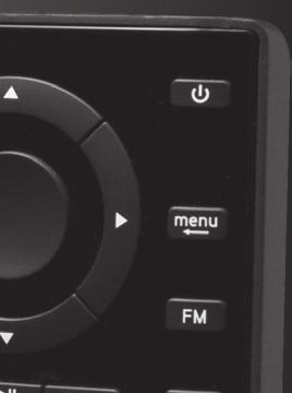
8 Introduction Starmate 8 Functions Up and Down Buttons Press to preview and tune to channels through the channel lineup; also press to scroll through lists and highlight menu items direct Number Buttons Press to tune to a stored favorite channel, press and hold to store a favorite channel; also enter a channel number. Left and Right Buttons Press to search for channels by category. menu FM jump Pause and Replay Buttons Pause, rewind, and replay up to 30 minutes of live radio. Power Button Press to turn Radio on and off. Select Button Press to confirm selection of highlighted items in a menu or list. Menu Button Press to access advanced features and configuration options; in configuration options, press and hold to return to main display screen. FM Button Press to access and cycle through FM presets. Jump Button Press to directly access traffic and weather for the city of your choice; or press it to go back to the previous channel to which you were listening. Direct Button Press first before entering the channel number, to directly tune to a channel. 8
9 Introduction PowerConnect Vehicle Dock Color-Coded Connections The color-coded PowerConnect Vehicle Dock makes it simple to connect. Just match the colors on the cable ends to the colors on the dock to see what goes where. Front View PWR FM AUDIO ANT PWR (Red) Connection for PowerConnect Power Adapter. FM (Blue) Connection for optional FM Direct Adapter (sold separately). Docking Rails Fits into slots on the rear of Starmate 8 to secure the Radio. AUDIO (Green) Connection for Aux In Cable or optional Cassette Adapter (sold separately). ANT (Silver) Connection for the Magnetic Mount Antenna. 9
10 Vehicle Installation 1 menu FM jump direct menu FM jump WARNING! DO NOT attempt to install Starmate 8 while driving. Park your vehicle in a safe location before beginning installation. Step 1: Choose a Location for Your Radio When installing Starmate 8 in your vehicle, choose a location where it will not block your vision, interfere with the controls, or obstruct the air bag. The location should be easily accessible and provide good visibility of the display, and should not be located where it will be in direct sunlight, which will affect the visibility of the display screen. Several examples of Starmate 8 mounted in a vehicle are shown: A is the on dash method using the Dash Mount, and B is the vent clip method using the Vent Mount. Option 1 Option 2 A direct A. 10
11 Vehicle Installation Option 3 A. Option 4 Option 5 B. B. 11
12 Vehicle Installation Step 2: Install the Vent or Dash Mount Follow the instructions on the next several pages for the mounting method you have selected. NOTE! The PowerConnect Vehicle Dock included with Starmate 8 is compatible with the T-slot style Dash and Vent Mounts. If you have an existing Dash Mount or Vent Mount in your vehicle, you can continue to use it with this dock, and skip this step. Installing the Dash Mount: CAUTION! The adhesive used on the Dash Mount may be difficult to remove. Do not install this mount on leather surfaces (contact your automobile dealership if you are unsure about your dash surface), and make sure the air temperature is at least 60 F (15 C) during installation. If it s not at least 60 F, turn on the heater in your vehicle to bring the temperature up to 60 F. 1. Locate a flat surface for the Dash Mount. Make sure there is ample room for the PowerConnect Vehicle Dock and Starmate 8 Radio when installed. 2. Set the orientation of the Dash Mount before adhering it. Loosen the knob and adjust the adhesive foot for the location you selected in Step 1: Choose a Location for I Your Radio on page 10: II Option 1 & Option 3 should be oriented as I. Option 2 should be oriented as II. 3. The dock mounting plate can be tilted in different directions. Adjust as necessary for your particular vehicle. When the orientation is 12
13 Vehicle Installation correct, tighten the knob. Knob Adhesive Foot Dock Mounting Plate 4. Attach the Dash Mount to the PowerConnect Vehicle Dock using the provided screws. 5. Clean the mounting surface in the vehicle with the alcohol preparation pad and let it dry thoroughly. 6. Peel off the adhesive liner. Position, press, and hold the Dash Mount and PowerConnect Vehicle Dock in place for 30 seconds. IMPORTANT! Allow the Dash Mount adhesive to cure (dry) for a minimum of 2-4 hours before using the mount. The best adhesion occurs after 24 hours. TIP! To remove the Dash Mount, carefully lift the adhesive pad with your fingers or a spoon. Warming the pad with a hair dryer for several minutes will help soften the adhesive. 13
14 Vehicle Installation Installing the Vent Mount: 1. Locate a vent with horizontal louvers sturdy enough to hold your PowerConnect Vehicle Dock and Starmate 8 Radio. 2. If the vent louvers in your vehicle are recessed, you may need to use the longer vent clamps with the Vent Mount. If so, Remove the shorter vent clamps and install the longer ones into the Vent Mount. Be sure to observe the orientation of the vent clamps as shown. Remove End Cap Extended Vent Clamps Short Vent Clamps Slide Short Vent Clamps Out Slide Extended Vent Clamps In Replace End Cap 14
15 Vehicle Installation 3. Attach the Vent Mount to the PowerConnect Vehicle Dock using the provided screws. Note! For greater clarity, the next illustration does not show the dock attached to the Vent Mount, however, the dock should be attached before continuing. 4. Push the Vent Mount onto the vehicle vent as shown (1) until it hooks on the rear of the vent louver (2) PUSH Dash Dash HOOKED Dash Vent FOOT Louver Vent TILT ADJUSTMENT HOLES Vent 5. Rest the foot against the bottom of the vent (2), and adjust the tilt of the Vent Mount by repositioning the foot to a different adjustment hole (3). TIP! To remove the Vent Mount, push the mount into the vent. Then lift up until disengaged from the rear of the vent louver, and remove the Vent Mount. 15
16 Vehicle Installation Step 3: Mount the Magnetic Mount Antenna Mount the Magnetic Mount Antenna on the outside of your vehicle, on a horizontal surface that will always face the sky. The antenna contains a strong magnet which will stick to any metal part of your vehicle, but will not damage the vehicle. To install the Magnetic Mount Antenna: 1. Choose the best location for your antenna considering your own personal situation. Pay particular attention to any accessories that you may have like luggage racks and how frequently you may use them. Magnet Sedan/Coupe: We recommend mounting the antenna above either the front windshield or the back window as shown. 16
17 Vehicle Installation SUV: We recommend mounting the antenna at the rear of the roof as shown. Convertible: We recommend mounting the antenna at the leading edge of the trunk as shown. Pickup Truck: We recommend mounting the antenna above the front windshield as shown. IMPORTANT! Consult a professional installer if your vehicle roof or hood is non-metallic (i.e., fiberglass), or you have difficulty finding a location for your antenna. 17
18 Vehicle Installation 2 Attach the Rubber Tail to the antenna and press the antenna cable into the Rubber Tail. The Rubber Tail will help to position the antenna the correct distance from the edge of the roof or trunk lid. 3 Clean the surface of the selected mounting location using the alcohol preparation pad and let it dry thoroughly. Protective Material Magnetic Mount Antenna (Upside-Down) Rubber Antenna Tail Strain Relief 4 Follow the Tips and Cautions shown Antenna Cable on the next several pages, and place the antenna in the location you selected. Peel the protective material from the adhesive strips and press the Rubber Tail firmly into place on the vehicle. 5 Continue to press firmly down on the Rubber Tail for another 30 seconds. At room temperature (68 F), maximum adhesion usually occurs within 72 hours. During this period, avoid car washes and other contact with the antenna and the Rubber Tail. 18
19 Vehicle Installation TIP! Mount the antenna on the roof (for most vehicles) or trunk (for convertibles) where it has a clear view of the sky in all directions. 19
20 Vehicle Installation TIP! Mount the antenna on the roof where it has at least 3 inches of clear space around it. 3 TIP! Use the supplied Rubber Tail to cover and protect the antenna cable. CAUTION! Don t mount the antenna closer than 3 inches from the edge of the roof. Use the supplied Rubber Tail as a guide for judging proper length and correct positioning. 20
21 Vehicle Installation CAUTION! Don t mount the antenna inside the vehicle, for example, on the dashboard. CAUTION! Don t mount the antenna on any of the vehicle s front, back or side pillars. CAUTION! Don t mount the antenna close to a roof rack. Adjust the rack so it s further away from the antenna or move the antenna closer to the center of the roof. 21
22 Vehicle Installation CAUTION! Don t mount the Magnetic Mount Antenna close to another antenna. Mount it at least 3 inches away. TIP! Always be careful to include enough slack in your cable to accommodate open doors or trunk lids. Use things typically found around the home, like electrical tape, to secure cables in areas so that hinges do not pinch the cable with the door. Hide any excess cable in the trim. 22
23 Vehicle Installation Step 4: Route the Magnetic Mount Antenna Cable Before you begin routing the antenna cable, read these general instructions for how to route and hide the antenna cable. Then route your antenna cable according to the instructions which follow for your specific type of vehicle. Use a blunt plastic putty knife, a credit card, a plastic knife, or a similar blunt tool to lift the rubber window moulding Tuck the cable under the moulding around the window Feed cable under rubber moulding around window 23

24 Vehicle Installation Route cable out from under rear windshield moulding and tuck into weatherstripping around trunk opening Avoid sharp bends by running cable through weatherstripping for several inches Pull weatherstripping from trunk opening Tuck cable into weatherstripping. Route cable through weatherstripping several inches to avoid sharp bends Pull cable out of weatherstripping and route through trunk to cabin Route cable out of window moulding and into weatherstripping around trunk opening 24

25 Vehicle Installation Bring cable out of weatherstripping and into trunk Route cable along trunk wall and into cabin through gap or conduit, along existing wiring harness Route cable along trunk wall and into cabin 25

26 Vehicle Installation Use a blunt plastic putty knife or similar blunt tool to lift edge of interior trim and tuck cable under trim. Continue towards front of vehicle Route cable under trim or upholstery Continue routing cable under trim or carpet towards front of vehicle Route cable from trunk under interior trim, into cabin and towards front of vehicle 26

27 Vehicle Installation Continue routing cable under carpet or console to radio location Pull carpet or mat back Coil excess cable under carpet or mat Bring cable out from trim and route under carpet to dashboard or console Bring cable out from trim TIP! Always be careful to include enough slack in your cable to accommodate open doors or trunk lids. Use things typically found around the home, like electrical tape, to secure cables in areas so that hinges do not pinch the cable with the door. Hide any excess cable in the trim. 27
28 Vehicle Installation Sedan/Coupe With Antenna Placed at the Rear of the Roof: Feed the antenna cable from the antenna underneath the rubber molding around the rear window. Use a blunt plastic putty knife or similar blunt tool to lift the rubber molding around the rear window and tuck the antenna cable underneath the molding. Route the antenna cable around and down the window to the lowest point. If your rear window does not have rubber molding, we recommend consulting a professional installer. 2. Route the antenna cable out of the window molding and into the rubber weather stripping around the trunk opening. Lift the weather stripping from the opening and tuck the cable inside it, then replace the weather stripping. To avoid sharp bends in the cable, run the cable inside the weather stripping for a few inches, then remove the cable from the weather stripping inside the trunk. Keep the cable away from hinges, gears, etc., that could damage it. 3. Route the cable out from the rubber weather stripping and along the trunk wall. Continue routing the cable into the vehicle cabin through a conduit or along an existing wiring harness. 4. Route the cable through the main cabin area under the interior trim, towards the front of the vehicle. Use a blunt plastic putty knife or similar blunt tool to lift the plastic trim just enough to tuck the cable under underneath. Avoid side airbag locations on back pillars and above the doors. Airbag locations are marked
29 Vehicle Installation with SRS logos. Be careful not to crimp or cut the cable. 5. Bring the cable out from the trim near the front of the cabin and route it under the carpet toward the dashboard or console. Coil any excess cable in a hidden location, such as under the carpet, keeping it away from any vehicle pedals or controls. Secure the excess cable with wire ties (purchased separately). 6. Bring the end of the cable out at the PowerConnect Vehicle Dock location. Leave yourself enough cable so you can easily connect it to the antenna connector of the dock. 7. Continue with Step 5: Connect the Magnetic Mount Antenna and PowerConnect Power Adapter on page 34. Sedan/Coupe With Antenna Placed at the Front of the Roof 1. Feed the antenna cable from the antenna underneath the rubber molding around the windshield. Use a blunt plastic putty knife or similar blunt tool to lift the rubber molding around the windshield and tuck the antenna cable underneath the molding. Route the antenna cable around and down the windshield to the lowest point. 2. At the lowest corner of the windshield, route the cable out of the windshield molding and into the rubber weather stripping around the door opening. Lift the weather stripping from the opening and tuck the cable inside it, then replace the weather stripping. Run the cable inside of the weather stripping to the bottom of the 29
30 Vehicle Installation 30 door opening. 3. Pull the cable out of the weather stripping at the bottom of the door opening and route it under the carpet toward the dashboard. Coil any excess cable in a hidden location, such as under the carpet, keeping it away from any vehicle pedals or controls. Secure the excess cable with wire ties. 4. Bring the end of the cable out at the PowerConnect Vehicle Dock location. Leave yourself enough cable so you can easily connect it to the antenna connector of the dock. 5. Continue with Step 5: Connect the Magnetic Mount Antenna and PowerConnect Power Adapter on page 34. Sport Utility Vehicle (SUV) 1. Feed the antenna cable underneath the rubber weather stripping of the rear tailgate window/door and route the cable along the rear hatch. Lift the weather stripping from the opening and tuck the cable inside it, then replace the weather stripping. Pull the cable out from weather stripping and route it into the cabin under the interior trim. Avoid hinges or gears that could crimp or cut the cable. 2. Route the cable through the SUV s main cabin area under the interior trim, towards the front of the vehicle. Use a blunt plastic putty knife or similar blunt tool to lift the
31 Vehicle Installation plastic trim just enough to tuck the cable under underneath. Avoid side airbag locations on back pillars and above the doors. Airbag locations are marked with SRS logos. Be careful not to crimp or cut the cable. 3. Bring the cable out from the trim near the front of the cabin and route it under the carpet toward the dashboard or console. Coil any excess cable in a hidden location, such as under the carpet, keeping it away from any vehicle pedals or controls. Secure the excess cable with wire ties (purchased separately). 4. Bring the end of the cable out at the PowerConnect Vehicle Dock location. Leave yourself enough cable so you can easily connect it to the antenna connector of the dock. 5. Continue with Step 5: Connect the Magnetic Mount Antenna and PowerConnect Power Adapter on page 34. Convertible 1. Bring the antenna cable from the antenna into the trunk at the front edge of the trunk lid. Keep any bends in the cable loose. Tape or tie the cable along the inside of the trunk lid to the trunk lid hinge strut. 2. Allow enough slack in the cable so the trunk lid can easily open and close and keep the cable away from hinges, gears, etc., that could crimp or cut it. Route the cable along the trunk wall and into the cabin through a conduit or along an existing wiring harness. 31
32 Vehicle Installation 3. Route the cable through the main cabin area under the interior trim, towards the front of the vehicle. Use a blunt plastic putty knife or similar blunt tool to lift the plastic trim just enough to tuck the cable under underneath. Avoid side airbag locations on back pillars and above the doors. Airbag locations are marked with SRS logos. Be careful not to crimp or cut the cable. 4. Bring the cable out from the trim near the front of the cabin and route it under the carpet toward the dashboard or console. Coil any excess cable in a hidden location, such as under the carpet, keeping it away from any vehicle pedals or controls. Secure the excess cable with wire ties (purchased separately). 5. Bring the end of the cable out at the PowerConnect Vehicle Dock location. Leave yourself enough cable so you can easily connect it to the antenna connector of the dock. 6. Continue with Step 5: Connect the Magnetic Mount Antenna and PowerConnect Power Adapter on page 34. Pickup Truck 1. Use a blunt plastic putty knife or similar blunt tool to lift the rubber molding around the windshield and tuck the antenna cable underneath it. 2. Continue tucking the cable underneath the windshield molding around the windshield to the lowest corner. 3. At the lowest corner of the windshield, route the cable out of the windshield 32
33 Vehicle Installation molding and into the rubber weather stripping around the door opening. Lift the weather stripping from the opening and tuck the cable inside it, then replace the weather stripping. Run the cable inside of the weather stripping to the bottom of the door opening. 4. Pull the cable out of the weather stripping at the bottom of the door opening and route it under the carpet toward the dashboard. Coil any excess cable in a hidden location, such as under the carpet, keeping it away from any vehicle pedals or controls. Secure the excess cable with wire ties. 5. Bring the end of the cable out at the PowerConnect Vehicle Dock location. Leave yourself enough cable so you can easily connect it to the antenna connector of the dock. 6. Continue with Step 5: Connect the Magnetic Mount Antenna and PowerConnect Power Adapter on page
34 Vehicle Installation Step 5: Connect the Magnetic Mount Antenna and PowerConnect Power Adapter 1. Plug the Magnetic Mount Antenna into the silver ANT connector on the PowerConnect Vehicle Dock. AUDIO ANT 2. Insert the PowerConnect Power Adapter into your vehicle s cigarette lighter or power adapter socket. 3. Plug the PowerConnect Power Adapter into the red PWR connector on the dock. PWR FM 34
35 Vehicle Installation Step 6: Connect the Audio To play Sirius audio through your vehicle s stereo or FM radio, decide on one of the following audio connection options: Option 1: Best: Use the provided Aux In Cable if your vehicle s stereo system has an auxiliary input connection or jack. Refer to your vehicle s owners manual to find the location of the auxiliary input jack, or consult the vehicle dealer. TIP! The auxiliary input jack may be located on the face plate of the vehicle radio, on the back of the radio, anywhere on the front dash panel, inside the glove compartment, or inside the center console in between the front seats. Option 2: Better: Use a Cassette Adapter if your vehicle has a builtin cassette player. Cassette Adapters are sold separately and can be purchased from an electronics retailer, or go to accessories. Option 3: Good: Use the PowerConnect feature of Starmate 8. PowerConnect plays the audio through your vehicle s FM radio. Option 4: Best: Use the FM Direct Adapter. If none of the previous three audio connection options will work in your vehicle, then you will need to use the FM Direct Adapter (FMDA) (sold separately). The FMDA needs to be installed by a professional installer and directly connects Starmate 8 to your vehicle s FM radio. To learn more, check with the retailer where you bought your Radio, or go to Follow the installation instructions in the next several sections for the audio connection option that you have selected. 35
36 Vehicle Installation Option 1: Aux In Cable Installation Instructions 1. Plug one end of the Aux In Cable into the green AUDIO connector on the dock. 2. Plug the other end into the auxiliary input jack of your vehicle s stereo system. AUDIO ANT 3. Insert Starmate 8 into the dock, aligning the Radio against the rear of the dock so that the rails on the dock fit into the mounting slots in the back of the Radio. 1 menu FM jump direct 4. Power on your Starmate 8 by pressing the Power button. 5. Be sure the vehicle is outside and the antenna has a clear view of the sky. Verify that you are receiving the Sirius signal. There should be at least two bars on the lower left corner of the main display screen that denotes antenna signal strength. You can also press menu and then press to scroll to and menu FM 36
37 Vehicle Installation highlight Signal Indicator. Press the Select button. The Satellite and Terrestrial bars show the strength of the signal being received. If the signal reception is good, press and hold menu to return to the main display screen. 6. Ensure Starmate 8 is tuned to channel 184, the Sirius Preview channel. Upon power up, Starmate 8 should tune to channel 184 by default, when it s not yet activated. If it s not on channel 184, refer to Listening to Satellite Radio on page 50 to learn about how to tune a channel. 7. Turn on your vehicle s stereo system. Set it to play from the auxiliary input source. You should hear channel 184, the Sirius Preview channel, through your vehicle s stereo system. You are now ready to activate your Starmate Sirius Preview To Activate, Call Signal Indicator SATELLITE TERRESTRIAL 8. The audio level output of Starmate 8 can be increased or decreased as necessary to match the audio levels of other sources in your vehicle. Refer to Set Audio Level on page 76. If the signal reception is good, showing at least two bars in the lower left corner of the display, but there is no Sirius audio, be sure the vehicle s stereo system is set to the auxiliary input source (step 7). Also be sure that the audio level is set high enough to be heard (step 8). Refer to Troubleshooting on page 82 for additional help. 37
38 Vehicle Installation AUDIO ANT PWR FM Option 2: Cassette Adapter Installation Instructions 1. Plug the Cassette Adapter into the green AUDIO connector on the dock. 2. Insert the Cassette Adapter into the vehicle s cassette deck. You may need to turn on your vehicle s stereo system in order to do so. 3. Insert your Starmate 8 into the dock, aligning the Radio against the rear of the dock so that the rails on the dock fit into the mounting slots in the back of the Radio. 1 menu FM jump direct Power on your Starmate 8 by pressing the Power button. 5. Be sure the vehicle is outside and the antenna has a clear view of the sky. Verify that you are receiving the Sirius signal. There should be at least two bars on the lower left corner of the main display screen that denotes antenna signal strength. You can also press menu and then press to scroll to and highlight Signal Indicator. Press the Select button. The Satellite and Terrestrial bars show the strength of the signal being received. If the signal menu FM
39 Vehicle Installation reception is good, press and hold menu to return to the main display screen. 6. Ensure Starmate 8 is tuned to channel 184, the Sirius Preview channel. Upon power up, Starmate 8 should tune to channel 184 by default, when it s not yet activated. If it s not on channel 184, refer to Listening to Satellite Radio on page 50 to learn about how to tune a channel. 7. Turn on your vehicle s stereo system. Set it to play from the cassette source. You should hear channel 184, the Sirius Preview channel, through your vehicle s stereo system. You are now ready to activate your Starmate Sirius Preview To Activate, Call Signal Indicator SATELLITE TERRESTRIAL 8. The audio level output of Starmate 8 can be increased or decreased as necessary to match the audio levels of other sources in your vehicle. Refer to Set Audio Level on page 76. If the signal reception is good, showing at least two bars in the lower left corner of the display, but there is no Sirius audio, be sure the vehicle s stereo system is set to the cassette source (step 7). Also be sure that the audio level is set high enough to be heard (step 8). Refer to Troubleshooting on page 82 for additional help. 39
40 Vehicle Installation Option 3: PowerConnect Installation Instructions menu 1. Insert your Starmate 8 into the dock, aligning the Radio against the rear of the dock so that the rails on the dock fit into the mounting slots in the back of the Radio direct FM jump 2. Power on your Starmate 8 by pressing the Power button. menu FM 3. Be sure the vehicle is outside and the antenna has a clear view of the sky. Verify that you are receiving the Sirius signal. There should be at least two bars on the lower left corner of the main display screen that denotes antenna signal strength. You can also press menu and then press to scroll to and highlight Signal Indicator. Press the Select button. 184 Sirius Preview To Activate, Call
41 Vehicle Installation The Satellite and Terrestrial bars show the strength of the signal being received. If the signal reception is good, press and hold menu to return to the main display screen. Signal Indicator SATELLITE 4. You ll first need to find an available FM channel. An available FM channel TERRESTRIAL is one that s not being used by an FM radio station in your area. When you tune your FM radio to an available channel, you should only hear static or silence not talk or music. We recommend one of the following methods to find an available FM channel: a. Use the SiriusXM FM Channel Finder at fmchannel. Go to the website and enter your zip code. The Channel Finder will suggest a list of available FM channels in your area. For convenience, write down or print out the list. OR b. Manually tune through your local FM channels on your vehicle s FM radio. Locate and create a list of channels that aren t being used by any FM radio station. Write down the list. Once you have created your list of available FM channels, you will need to find the one that provides the best match for Starmate 8. TIP! You ll need to use the Manual tune function on your vehicle s FM radio to tune through every FM channel one-by-one. Turn on your vehicle s FM radio. Start at 88.1 and use the Manual tune function on your vehicle s FM radio to tune through each FM channel one-by-one (88.1 followed by 88.3 etc.) to locate channels that aren t being used by a local FM radio station. Write down each FM channel that has only static or silence on it, until you 41
42 Vehicle Installation 1 menu direct FM jump reach Ensure Starmate 8 is tuned to channel 184, the Sirius Preview channel. Upon power up, Starmate 8 should tune to channel 184 by default, when it s not yet activated. If it s not on channel 184, refer to Listening to Satellite Radio on page 50 to learn about how to tune a channel. 6. Pick the first FM channel on your list from step 4. Turn on your vehicle s FM radio (if you have not already done so) and tune it to this FM channel Set your Starmate 8 to transmit on the same FM channel that you have selected in step 4: i. Press menu. MATCH FM CHANNELS ii. Press to scroll to and highlight FM Settings and press the Select button. iii. Press to scroll to and highlight FM Channels. Press the Select button. iv. Press to scroll to and highlight the storage location FM 2 and press the Select button. v. Tune to the available FM channel you choose in step 4. Press and FM 1 FM 2 FM 3 FM 4 FM 5 FM Channels 97.9 current 42
43 Vehicle Installation to tune in steps of.2, i.e., 99.3 to Press and to tune in steps of 1, i.e., 99.3 to Press the Select button to select the FM channel. vi. Start Using is highlighted. Press the Select button. vii. The FM channel you selected will be confirmed on the display screen. Starmate 8 will tune to the FM channel FM Set your vehicle radio to the above channel to enable audio. 8. You should hear channel 184, the Sirius Preview channel, through your vehicle s stereo system. If you are satisfied with the sound quality, the installation is complete. You are now ready to activate your Starmate If the selected FM channel doesn t work well for you, work down the list of FM channels until you find one with which you are satisfied. Each time, you will need to tune your vehicle s FM radio to the FM channel and then set your Starmate 8 to transmit on the same FM channel (steps 6 & 7). If the signal reception is good, showing at least two bars in the lower left corner of the display, but there is no Sirius audio, verify that both Starmate 8 and your vehicle s FM radio are tuned to the same FM channel (steps 6 & 7). Also ensure the chosen FM channel is a suitable one to use in your area (step 4). Verify that nothing is plugged into the AUDIO connector on the PowerConnect Vehicle Dock. Refer to Troubleshooting on page 82 for additional help. 43
44 Vehicle Installation Option 4: FM Direct Adapter (FMDA) Installation The FMDA needs to be installed by a professional installer. Professional installation can help improve your Radio s reception and significantly reduce the visibility of wires. To learn more, check with the retailer where you bought your Radio, or go to 44
45 Subscribe You can either follow the general activation and subscription process or use the on-board activation guide to activate your Starmate 8 and subscribe to the Sirius service. General activation and subscription process: Subscribe to the Sirius service by following these steps: 1. Make sure your Starmate 8 is turned on, tuned to channel 184, the Sirius Preview channel, and receiving the Sirius signal so that you can hear the Sirius audio. 184 Sirius Preview 2. When you first turn on Starmate 8, the Sirius channel lineup may automatically update after the initial startup sequence. Wait until any channel updates have completed before pressing any buttons. Once the channels have been updated, the Radio will automatically tune to channel Make a note of the Sirius ID. You can find it: by selecting Sirius ID in menu items by tuning to channel 0 (zero) on a label on the bottom of the gift box on the label on the back of your Starmate 8 4. To subscribe: To Activate, Call *The phone number shown above may differ from the one shown on your Starmate 8. All numbers are valid. Online: Go to to access or set up an online account, subscribe to the service, and activate your Radio. OR By phone: Call
46 Subscribe 5. Activation usually takes less than 5 minutes after you have completed the subscription process, but sometimes may take longer. We recommend that your Radio remain on until activated. When your service is activated, Starmate 8 will display an alert message. To continue, press any button. Subscription Update Your subscription has been successfully updated Press any button to continue Press or to tune to other channels, and or to browse the different categories of channels. Learn what all the buttons do by turning to Navigation Basics on page 48. Activation guide: For your convenience, Starmate 8 has an on-board activation guide. You can activate your Radio and subscribe to the Sirius service by using this guide, where you will be guided step-by-step through the subscription process. To access and use the guide, simply follow these steps: 1. When you first turn on Starmate 8, the Sirius channel lineup may automatically update after the initial startup sequence. Wait until any channel updates have completed before pressing any buttons. Once the channels have been updated, the Radio will automatically tune to channel 184, the Sirius Preview channel. 2. Press menu. 3. Activate Radio will be highlighted. Press the Select button. 4. Follow the directions on each successive screen until you complete the subscription process. Menu Activate Radio Sirius ID FM Settings JUMP Settings Brightness 46
47 Using Your Starmate 8 The Main Display When listening to a channel, information about the channel and what is currently playing is displayed. Channel Number 28 The Spectrum Tom Petty I Should Have Known It Channel Name Artist Name or Talk Show Host or Sports Teams/Score Antenna Signal Song/Program Title Strength or Talk Show Schedule or Game Time/Game Details 47
48 Using Your Starmate 8 Navigation Basics Power Button Pressing the Power button turns Starmate 8 On or Off. Navigation Buttons Pressing Left, Right, Up, and Down navigates through various features and functions of Starmate 8. Left or Right button: Displays the channel categories such as Rock, Pop, Sports, Talk/News, etc. Repeated presses cycle through the categories one at a time. Also, decreases or increases the settings of various menu options such as Brightness, Audio Level, etc. Up or Down button (press and release): Immediately tunes to the next or previous channel in the channel lineup. Also, scrolls through lists and highlights an item in the list. Up or Down button (press and hold): Continuously scrolls through any list. While on the main display screen, continuously scrolls through the channel lineup and briefly displays the information of each channel. When the button is released, Radio tunes to the last channel it had scrolled to in the channel lineup. Select Button Pressing the Select button selects a highlighted item in a menu or list and confirms settings. Pause and Replay Buttons Replays approximately 30 minutes of live radio. plays/pauses, rewinds, and fast-forwards through temporarily stored content. 48
49 Using Your Starmate 8 Menu Button menu Pressing menu displays various options to make setup and feature changes. Pressing menu when in menu options returns to the previous menu option screen until menu options is exited. Pressing and holding menu returns to the main display screen in most instances. FM Button FM Pressing FM provides easy tuning of FM presets for optimized PowerConnect performance. Repeatedly pressing FM displays and cycles through the list of preset FM channels one at a time. The Radio automatically tunes to the displayed FM channel. Pressing and holding FM accesses the FM Settings menu. It is not available when Aux In Cable or Cassette Adapter is used for audio connection. Jump Button jump Depending on how it is configured, pressing jump either tunes to the channel broadcasting traffic and weather conditions of a city of your choice, selected from a list of the 22 most congested cities, or tunes to the previous channel that was being played. Pressing it again returns it to the original channel. Direct Button Pressing direct prompts for the entry of a channel number using the number buttons. Once the channel number is entered, the Radio directly tunes to the new channel. direct Number Buttons Each number button stores a favorite channel in its button location and provides one touch access to it afterward. Number buttons also directly tune to a channel when the channel number is entered after pressing direct. 49
50 Using Your Starmate 8 Listening to Satellite Radio Tune to a channel: 1. Press and release and to immediately tune to the next or previous channel. 2. Press and hold and to quickly scroll through the channels. Release to tune to the channel that is displayed. View a category: Channels are organized into categories to make it easier for you to find the ones that suit your taste. 1. To view channels in a category in list mode press or. 2. Scroll through the category using and, and find the channel you want to tune. 3. Press the Select button to select the channel, or press or to view channels in the previous or next category Rock Pearl Jam Radio Pearl Jam/Better Man Grateful Dead Grateful Dead/Truckin Margaritaville Jimmy Buffett/Fins TIP! To briefly listen to each channel in the category, scroll to and highlight Scan at the end of the category list and press the Select button. Refer to Scanning Channels in a Category on page 54 to learn more about Scan. 50
51 Using Your Starmate 8 Direct Tune A channel can be tuned directly by entering the channel number using the number buttons. 1. To directly tune to a channel press direct. 2. Use the number buttons 0-9 to enter the channel number and wait a moment until the channel is tuned, or press the Select button to immediately tune to the channel. Direct Tune Enter channel # 6 2 _ Return to Main Display Screen Pressing and holding menu in most instances will return you to the main display screen. In some cases, you may need to follow the instructions on the display screen. 51
52 Using Your Starmate 8 Jump Depending upon how you configure the mode, pressing jump will either go to the traffic and weather channel for the city of your choice, which you select from a list of the 22 most congested cities, or go to the previous channel to which you were listening. If Jump is set to Traffic, when you press jump and the traffic/weather broadcast of your selected city is not immediately available, a message will be displayed at the bottom of the screen to indicate that a jump is pending. Once the traffic/weather report is ready to be broadcast, the Radio will automatically tune to the traffic/ weather channel. Since a channel may broadcast the traffic and weather reports of more than one city, you may have to wait a few minutes for the broadcast of your selected city. 28 The Spectrum Tom Petty I Should Have Known It Boston Pending If Jump is set to Last Channel, pressing jump will immediately tune to the previous channel to which you were listening. Pressing jump while a jump is pending will cancel the jump. Pressing jump after the Radio has tuned to the traffic/weather or desired channel, will return it back to the channel to which you had been listening immediately prior to pressing jump. TIP! By default jump is configured to tune to a traffic/weather channel. To select a city for traffic and weather, or to configure jump to tune to the last channel to which you were listening, refer to Jump Settings on page
53 Using Your Starmate 8 Favorite Channels You can set up to 10 of your favorite channels so you can easily access them. Each favorite channel can be assigned to a number button. To assign a favorite channel to a number button: 1. Tune to the desired channel. 2. Press and hold a number button between 0-9 that you want to assign to that favorite channel. An advisory with the channel number and name will be displayed on the screen confirming that the channel has been assigned. Favorite Saved 10 The Pulse saved as Favorite 1 To listen to a favorite channel: 1. Press the number button between 0-9 that was assigned to the desired favorite channel. Starmate 8 will tune to that channel. TIP! When you are at the main display screen, press to see your list of favorite channels. Scroll to highlight a favorite and press the Select button to listen to that channel. 53
54 Using Your Starmate 8 Scanning Channels in a Category You can scan a category and listen to each channel for 10 seconds before Starmate 8 automatically tunes to the next channel. If you want to stay tuned to the channel being played and stop the scan, just press the Select button. To scan a category: 1. Press or until the desired category is displayed. 2. Scroll down to highlight the last item in the category which will be Scan and the category name. 3. Press the Select button. The scan will begin. 4. Press the Select button to stop the scan, and to continue to listen to the channel currently being played, or press or to return to the channel you were listening to before you began the scan > Pop The Blend Phil Collins/Take Me Hom Love Dionne Warwick/Heartbr Scan Pop Scanning 70s on 7 Neil Diamond/Sweet Caro 80s on 8 The Hooters/And We Dan 90s on 9 Ace of Base/The Sign 54
55 Using Your Starmate 8 FM Presets FM presets make it easy to quickly access stored FM channels and choose a new FM channel from them. Use FM presets when you use PowerConnect or the FMDA to listen to your Starmate 8 through your vehicle s FM radio. (Refer to Option 3: PowerConnect Installation Instructions on page 40 for more information.) To use a different FM preset: 1. Press FM to display the current FM preset. 2. To display and select the next FM preset, press FM. The Radio will tune to the displayed FM channel. If the preset is the one you want, press menu or wait for the screen to time out. 3. Repeatedly pressing FM will cycle through the FM presets. 4. Set your vehicle s FM radio to the same FM channel. IMPORTANT! You need to ensure that your vehicle s FM radio is tuned to the same FM channel. TIP! To configure the list of preset FM channels, you need to find available FM channels in your area. Refer to Find Available FM Channels in Your Area on page 66. Next, refer to Set and Select an FM Channel on page FM Set your vehicle radio to the above channel to enable audio FM Set your vehicle radio to the above channel to enable audio. 55
56 Special Features Pause & Replay Pause & Replay gives you the opportunity to hear that again by temporarily storing and letting you access content of the currently tuned channel which played in approximately the last 30 minutes. Pressing or places Starmate 8 into Pause & Replay mode. To Play/Pause: TIP! This feature applies to the current channel to which you are listening, and for the current tuning and listening session only. Changing channels or turning off Starmate 8 removes the temporarily stored content from the Radio. 1. Press and release to pause the live broadcast. At this point the Radio will mute and continue to store live audio. 28 The Spectrum Tom Petty I Should Have Known It Length of Stored Content Behind Play/Pause Point 16:01-08:57 Time Behind Live Broadcast Pressing and releasing again will begin playing stored audio from the point at which the program was paused. TIP! Pressing (or pressing twice, if favorite channels are stored) will show the Replay List. A listing of artist names and song or show title are shown for the stored audio from most recent to oldest, beginning with entry called Go to Live. Press or to scroll to and highlight a song or program and press the Select button to play it. Choosing Go to Live exits Pause & Replay mode and resumes playing the live broadcast.
57 Special Features To listen to the previous track: 1. Press and release to rewind to the beginning of the current song or program. 2. Repeated press and releases skips backwards to the start of the previous songs or programs until the beginning of the stored audio is reached. When the beginning is reached, playback automatically begins. TIP! Pressing and holding rewinds through stored audio in 5 second intervals, which increases to 15 and then 30 second intervals the longer the button is pressed. Playback begins when the button is released. If beginning of the stored audio is reached, playback automatically begins. To listen to the next track: 1. Press and release to skip forward to the start of the next song or program. 2. Repeated press and releases skips forward to the beginning of the next songs or programs until the end of stored audio is reached. When the end is reached, Starmate 8 exits Pause & Replay mode and resumes playing the live broadcast. TIP! Pressing and holding advances through the stored audio in 5 second intervals, which increases to 15 and then 30 second intervals the longer the button is pressed. Playback begins when button is released. If end of stored audio is reached, Starmate 8 exits Pause & Replay mode and resumes playing the live broadcast. To listen to live broadcast: 1. Pressing and holding while Starmate 8 is in Pause & Replay mode exits Pause & Replay mode and resumes playing the live broadcast. 57
Dock & Play Radio with Vehicle Kit USER GUIDE
 Dock & Play Radio with Vehicle Kit USER GUIDE Table of Contents Introduction... 4 Features...4 Safety and Care Information...5 What s in the Box?...7 Onyx Functions....8 PowerConnect Vehicle Dock...9
1. If you are using the vent mounting method, attach the Vent Mount to the vehicle vent. 2. Insert your Onyx Plus into the dock.
 Vehicle Installation twx FM Option 3: PowerConnect Installation Instructions 1. If you are using the vent mounting method, attach the Vent Mount to the vehicle vent. 2. Insert your Onyx Plus into the dock.
Table of Contents. Where Else Can You Use Your onyx?... 75
 User Guide Table of Contents Introduction................... 5 Features........................... 6 Safety and Care Information.......... 7 What s in the Box?.................. 9 onyx Functions....................
User Guide. Stratus 7 Radio & Vehicle Kit
 User Guide Stratus 7 Radio & Vehicle Kit Table of Contents Introduction.... 5 General Precautions... 7 Warnings.... 8 What s in the Box?....10 Vehicle Installation...13 Location....14 Mounting the PowerConnect
Getting Started. Installing the Vehicle Kit for your Sportster 6 Satellite Radio
 Getting Started Installing the Vehicle Kit for your Sportster 6 Satellite Radio MENU BAND MEMO DISP MUTE Take your radio out of the box. You should have these. a b + 1 2 3 4 5 6 7 8 9 0 Sit. Stay. Have
LV1. Vehicle Kit LV1 QUICK START GUIDE. Listen to your Lynx Radio through your vehicle s stereo
 Vehicle Kit LV1 Listen to your Lynx Radio through your vehicle s stereo QUICK START GUIDE LV1 What s in the Box? ch - ch + Dash Mount PowerConnect Vehicle Dock Remote Control Vent Mount & Extended Vent
USER GUIDE DV3. Dock & Play Vehicle Kit
 USER GUIDE DV3 Dock & Play Vehicle Kit Table of Contents Compatibility.... 3 Introduction................................................. 4 Features... 4 Safety and Care Information.... 5 What s in the
Installation + User Guide
 Installation + User Guide Plug & Play Vehicle Kit Congratulations on the purchase of your new SUPV1C SIRIUS Universal Plug and Play Vehicle Kit Your new SUPV1C SIRIUS Universal Plug and Play Vehicle Kit
SIRIUS Starmate 4 Satellite Radio Receiver and Car Kit $99.99 USD. Kathleen Zarske Usability Specialist 12/10/2007
 SIRIUS Starmate 4 Satellite Radio Receiver and Car Kit $99.99 USD Kathleen Zarske Usability Specialist 12/10/2007 Overview How It Works Sirius Programming Starmate 4 Features Installation Alternative Satellite
KT-SR3000. SIRIUS Radio INSTRUCTIONS LVT A [J]
![KT-SR3000. SIRIUS Radio INSTRUCTIONS LVT A [J]](/thumbs/82/84953542.jpg "KT-SR3000. SIRIUS Radio INSTRUCTIONS LVT A [J]") SIRIUS Radio KT-SR3000 INSTRUCTIONS For Customer Use: Enter below the Model No. and Serial No. which are located either on the rear, bottom or side of the cabinet. Retain this information for future reference.
SIRIUS Radio KT-SR3000 INSTRUCTIONS For Customer Use: Enter below the Model No. and Serial No. which are located either on the rear, bottom or side of the cabinet. Retain this information for future reference.
V e h i c l e K i t. Installation & User Guide
 V e h i c l e K i t Installation & User Guide Congratulations on the Purchase of your new SIRIUS Stiletto Vehicle Kit! The Stiletto Vehicle Kit will maximize your safety and provide convenience by positioning
ADDITIONAL HOME KIT. User Guide
 i ADDITIONAL HOME KIT User Guide Table of Contents Introduction.................................................... 5 Features.................................................................... 6 Safety
KENWOOD COMPATIBLE SIRIUS SATELLITE RADIO TUNER
 SIRKEN1C KENWOOD COMPATIBLE SIRIUS SATELLITE RADIO TUNER Installation Guide Congratulations on your purchase of the SIRKEN1C the Kenwood Compatible SIRIUS Satellite Radio Tuner! Your new SIRIUS Tuner is
Car Kit Installation Guide
 Car Kit Installation Guide Table of Contents Introduction... 3 Welcome to XM...3 What s in the box?...3 Remote control functions...4 Vehicle Installation... 5 Step 1: Plan the installation... 6. Step 2:
KT-SR2000. SIRIUS Radio INSTRUCTIONS LVT A [J]
![KT-SR2000. SIRIUS Radio INSTRUCTIONS LVT A [J]](/thumbs/75/71718861.jpg "KT-SR2000. SIRIUS Radio INSTRUCTIONS LVT A [J]") SIRIUS Radio KT-SR2000 INSTRUCTIONS For Customer Use: Enter below the Model No. and Serial No. which are located either on the rear, bottom or side of the cabinet. Retain this information for future reference.
SIRIUS Radio KT-SR2000 INSTRUCTIONS For Customer Use: Enter below the Model No. and Serial No. which are located either on the rear, bottom or side of the cabinet. Retain this information for future reference.
Owner s Manual Supplement
 Uconnect 3.0 15UC3-526-AC Third Edition Uconnect 3.0 Chrysler Group LLC Printed in the USA Owner s Manual Supplement SECTION TABLE OF CONTENTS PAGE 1 UCONNECT 3.0...3 2 RADIO MODE...7 3 MEDIA MODE..............................................................
NEO CAR AUDIO. Neo AUXiN AUX INPUT INTERFACE. Instruction Manual
 NEO CAR AUDIO Neo AUXiN AUX INPUT INTERFACE Instruction Manual IMPORTANT NOTE Neo AUXiN Dip switch positions MUST be set BEFORE any other step is taken. Otherwise, the kit will not operate properly. See
Special Features Ticker 6. menu/alerts To turn the Sports Ticker on or off 1. menu/alerts 2. Alerts Select button 3. Sports
 Special Features twice. The first press selects all teams and the second press deselects all the teams in the league. The Ticker box next to each team will have a black background with white letters indicating
Xpress Satellite Radio Receiver
 Xpress Satellite Radio Receiver XMC10 Car Cradle Installation Guide -1- Released: 9-15-05 1 of 16 CONTENTS Congratulations... 3 Cautions and Warnings... 4 Contents XMC10... 5 Accessory Kit... 5 Installation/Wiring
XM Direct Home Tuner User Guide
 XM Direct Home Tuner User Guide Table of Contents Introduction.................................................... 5 Features.................................................................... 6 Safety
SV1C SIRIUS One SIRIUS Satellite Radio Plug and Play. User and Installation Guide
 SV1C SIRIUS One SIRIUS Satellite Radio Plug and Play User and Installation Guide CONGRATULATIONS! Your new SV1C SIRIUS One SIRIUS Satellite Radio Plug and Play Receiver lets you enjoy SIRIUS Satellite
Congratulations on the Purchase of your new SIRIUS SCC1 SiriusConnect Vehicle Tuner.
 Congratulations on the Purchase of your new SIRIUS SCC1 SiriusConnect Vehicle Tuner. The SCC1 SiriusConnect Vehicle Tuner is designed to work with any Sirius-Ready or SAT Radio Ready headunit. Some headunits
Congratulations on your purchase of the SIR-ALP1 the Alpine Compatible SIRIUS Satellite Radio Tuner!
 Installation Guide Congratulations on your purchase of the SIR-ALP1 the Alpine Compatible SIRIUS Satellite Radio Tuner! Your new SIRIUS Tuner is designed to work with 2004 and up Alpine Ai-NET headunits
USER GUIDE. Dock & Play Home Kit
 USER GUIDE Dock & Play Home Kit DH3 Table of Contents Compatibility.... 3 Introduction................................................. 4 Safety and Care Information.... 5 What s in the Box?... 6 Home
The Clarion SA200, a Sirius Satellite Radio approved antenna, has been designed and engineered to receive signal transmissions for Sirius' three
 d SA200 Introduction The Clarion SA200, a Sirius Satellite Radio approved antenna, has been designed and engineered to receive signal transmissions for Sirius' three satellites and network of ground-based
Xpress Satellite Radio Receiver
 Xpress Satellite Radio Receiver XMH10 Home Cradle Installation Guide -1- Released 9-15-05. 1 of 12 CONTENTS Congratulations... 3 Cautions and Warnings... 4 Contents XMH10... 5 Installation/Wiring Precautions...
ipod Owner s Manual Expand Your Factory Radio TOYOTA LEXUS / SCION Media Gateway PXAMG PGHTY1 add Harness Connection USB Port 1 Port Dip Switches
 Expand Your Factory Radio add ipod Harness Connection Dip Switches Port 1 Port 2 (See Manual) USB TOYOTA Owner s / Manual LEXUS / SCION Owner s Manual Media Gateway PXAMG PGHTY1 Media Gateway & Optional
Kawasaki Teryx 750 Cab Kit* Caution: Before using this product, read this manual and follow all Safety Instructions.
 Owner s Manual Model: Kawasaki Teryx 750 Kawasaki Teryx 750 Cab Kit* Caution: Before using this product, read this manual and follow all Safety Instructions. Safety Instructions Cab Kit Contents Hardware
G u i d e. I n s t a l l a t i o n. S K Y F i 2
 SKYFi2 install guide layout 6/20/06 4:47 PM Page 2 S K Y F i 2 I n s t a l l a t i o n G u i d e H o me a n d Ve h i c l e K it s C o n t e n t s : SKYFi2 Vehicle Adapter Kit Setup 2 SKYFi2 Installation
SUPH1 SIRIUS Plug and Play Home Kit
 SUPH1 SIRIUS Plug and Play Home Kit For use with most newer SIRIUS Plug and Play Receivers Installation Guide Congratulations on the Purchase of your new SUPH1 SIRIUS Plug and Play Vehicle Kit Your new
User Guide. Home Kit For XM Radios
 User Guide Home Kit For XM Radios Table of Contents Introduction....5 Features....................................................................... 6 Safety and Care Information...7 What s in the Box?..............................................................
TOYOTA TACOMA 2005 TRAILER WIRE HARNESS Preparation
 Preparation Part Number: 08921 04960 NOTE: Part number of this accessory may not be the same as the part number shown. Kit Contents Item # Quantity Reqd. Description 1 1 Converter Assembl y 2 1 Wire Harness
Pair of PMR446 Two-Way Personal Radios Model: TP391
 Pair of PMR446 Two-Way Personal Radios Model: TP391 USER MANUAL MANUALE D USO MANUEL DE L UTILISATEUR BEDIENUNGSANLEITUNG MANUAL DE USUARIO MANUAL DO USUÁRIO HANDLEIDING BRUKSANVISNING P/N:086L004722-016
Hatchback Wing Riser Kit
 Hatchback Wing Riser Kit 2015-06-11 Thank you for purchasing this PERRIN product for your car! Installation of this product should only be performed by persons experienced with installation of aftermarket
FD 125 Large-Format Card Cutter
 FD 125 Large-Format Card Cutter 3/201 OPERATOR MANUAL Page 2 Table of Contents SAFETY PRECAUTIONS... 4 Introduction... 5 Specifications... 5 Accessories... 5 Major Components and Assemblies... 6 Control
* * APPLICABLE MODELS: 2014 > MAZDA 3
 PART NUMBER: 0000 8C L46 GENUINE ACCESSORIES INSTALLATION INSTRUCTIONS Rev. AAA *550-0604-000* APPLICABLE MODELS: 204 > MAZDA 3 REQUIRED COMPONENTS: ITEM QTY DESCRIPTION Usage Chart MIRROR ASSEMBLY: Mirror
Expand Your Factory Radio. add. Satellite Radio. Harness Connection. Dip Switches. Port 1 Port USB. 2 (See Manual) Owner s Manual TOYOTA LEXUS / SCION
 Owner s Manual TOYOTA LEXUS / SCION") Expand Your Factory Radio Harness Connection add Satellite Radio Dip Switches Port 1 Port 2 (See Manual) USB TOYOTA Owner s / Manual LEXUS / SCION Owner s Manual Media GateWay Gateway ISSR12 PXAMG Table
Expand Your Factory Radio Harness Connection add Satellite Radio Dip Switches Port 1 Port 2 (See Manual) USB TOYOTA Owner s / Manual LEXUS / SCION Owner s Manual Media GateWay Gateway ISSR12 PXAMG Table
TOYOTA TACOMA TRAILER WIRE HARNESS Preparation
 Preparation Part Number: PT725-35120 Kit Contents Item Quantity Reqd. Description # 1 1 Flasher Assembly (F/A) 2 1 Wire Harness 3 1 Sub Wire Harness 4 2 Plastic Tie (300mm) 5 4 Plastic Tie (200mm) 6 13
AutoDAB Connect In-Car DAB Adapter User Guide
 AutoDAB Connect In-Car DAB Adapter User Guide www.autodab.com Table of Content INTRODUCTION... 1 CONTENTS OF PACKAGE... 2 INSTALLATION... 3 OPERATION CONTROLS... 8 STARTING UP THE SYSTEM... 11 USING REMOTE
11103RoadyXT_manual 6/19/06 11:02 AM Page 1
 11103RoadyXT_manual 6/19/06 11:02 AM Page 1 11103RoadyXT_manual 6/19/06 11:02 AM Page 2 FCC ID: RS2SA10177A Please note that the cables and antenna wire that have been supplied with your device are supplied
ipod Owner s Manual Expand Your Factory Radio add Honda/Acura Media PXAMG Gateway Media Gateway
 Expand Your Factory Radio add ipod PXAMG Automotive Media Gateway Owner s Owner s Manual Honda/Acura Media Gateway Media PXAMG Gateway PGHHD1 PXAMG Peripheral Electronics, a division of AAMP of America
BRM * This item is for consumer use only and it is not meant for commercial use.
 BRM 10 * This item is for consumer use only and it is not meant for commercial use. OWNER S MANUAL General Information Safety Before you undertake any exercise program, please be sure to consult with your
On-Line Cardio Theater Wireless Digital Transmitter Installation and Instruction Manual
 On-Line Cardio Theater Wireless Digital Transmitter Installation and Instruction Manual Full installation instructions accompany your Cardio Theater equipment order. This On-Line version of our Installation/Instruction
Signal Mirror Installation Instructions Toyota Tacoma
 Signal Mirror Installation Instructions 2005-2015 Toyota Tacoma THE safety accessory of the 21 st Century. P/N 210-0115-0 Rev. A4 (3/11/15), BTV 2005 Muth Mirror Systems, LLC Page 3 of 12PplPage 3 of 12
05 Toyota Camry SIRIUS Satellite Radio Operation Instructions
 05 Toyota Camry SIRIUS Satellite Radio Operation Instructions Reference Using your audio system Some basics This section describes some of the basic features on Toyota audio systems. Some information may
Subwoofer. - F required in S40 with low cargo compartment floor - G always required in V50 - H required in V50 with low cargo compartment floor
 1 of 26 Subwoofer 2 of 26 INTRODUCTION - NOTE! Read through the whole installation instruction before starting the work. - The front page gives the date of this edition and the edition it replaces - The
CLASS D MONO AMPLIFIER GM-D8601 GM-D9601. Owner s Manual
 CLASS D MONO AMPLIFIER GM-D8601 GM-D9601 Owner s Manual Before you start BE SURE TO OBSERVE THE FOLLOWING GUIDELINES:! Do not turn up the volume so high that you can t hear what s around you.! Use caution
User manual AWR-8000 / AWR Advanced Wireless Communications
 User manual AWR-8000 / AWR-8001 Advanced Wireless Communications THANK YOU! Thank you for your purchase of Advanced Wireless Communications AWR-8000 / AWR-8001 two-way radio. This portable two-way radio
TOYOTA TACOMA LED BED LIGHTS Preparation
 Preparation Part Number: PT948-35160 Kit Contents Item # Quantity Reqd. Description 1 1 Hardware Kit 2 1 Driver Side LED assembly 3 1 Passenger Side LED assembly 4 1 Main Wire Harness Hardware Bag Contents
Operating Instructions
 FM Transmitter 2 Operating Instructions PLEASE READ ALL THE INSTRUCTIONS COMPLETELY BEFORE USE AND SAVE THIS MANUAL FOR FUTURE REFERENCE. Before Use Please read IMPORTANT SAFETY INSTRUCTIONS on pages 10-11
JEEP JK ( 5 DOOR ) SLIMLINE II - FULL TRAY EXTREME RACK KIT
 SLIMLINE II - FULL TRAY EXTREME RACK KIT") JEEP JK ( 5 DOOR ) SLIMLINE II - FULL TRAY EXTREME RACK KIT FAJK001 / KRJW014T INSTALL TIME: 2.5 Hours NOTE: Your Jeep JK (5 Door) Extreme Roof Rack Kit consists of four boxes. (1) the Tray, (2) the Roll
JEEP JK ( 5 DOOR ) SLIMLINE II - FULL TRAY EXTREME RACK KIT FAJK001 / KRJW014T INSTALL TIME: 2.5 Hours NOTE: Your Jeep JK (5 Door) Extreme Roof Rack Kit consists of four boxes. (1) the Tray, (2) the Roll
TOYOTA Tundra 2014 Fender Flare Set
 2014 Part Number: 00016-34047 Accessory Code: TG1 Conflicts Note: Regular Cab Kit Contents Item # Quantity Reqd. Description 1 1 Left Front Fender Flare 2 1 Right Front Fender Flare 3 1 Left Rear Fender
Installation instructions, accessories. TV receiver, digital
 Installation instructions, accessories Instruction No 30756561 Version 1.1 5 Part. No. 30756181, 30756569 TV receiver, digital Volvo Car Corporation TV receiver, digital- 30756561 - V1.1 Page 1 / 36 Equipment
TRK-SR2 Install Guide 8/29/01 10:22 AM Page 1. TRK-SR2 Roof-Mount Satellite Radio Antenna Installation Guide
 TRK-SR2 Install Guide 8/29/01 10:22 AM Page 1 TRK-SR2 Roof-Mount Satellite Radio Antenna Installation Guide TRK-SR2 Install Guide 8/29/01 10:22 AM Page 2 TABLE OF CONTENTS About Installation..........................................
Signal Mirror Installation Instructions
 Signal Mirror Installation Instructions 2005-2010 Chevy Corvette C6 THE safety accessory of the 21 st Century. P/N 210-0144-0 Rev. A3 (9/29/2011), BTV 2007 Muth Mirror Systems, LLC Page 3 of 10PplPage
05 Toyota Solara SIRIUS Satellite Radio Operation Instructions
 05 Toyota Solara SIRIUS Satellite Radio Operation Instructions Reference Using your audio system Some basics This section describes some of the basic features on Toyota audio systems. Some information
ROOF RACK INSTALLATION INSTRUCTIONS (35, 45, 55 RAIL LENGTHS)
") ROOF RACK INSTALLATION INSTRUCTIONS (35, 45, 55 RAIL LENGTHS) ROOF RACK INSTALLATION INSTRUCTIONS (35, 45, 55 RAIL LENGTHS) NOTE: Perrycraft s products are manufactured to be installed into the skin of
ROOF RACK INSTALLATION INSTRUCTIONS (35, 45, 55 RAIL LENGTHS) ROOF RACK INSTALLATION INSTRUCTIONS (35, 45, 55 RAIL LENGTHS) NOTE: Perrycraft s products are manufactured to be installed into the skin of
С 800 CASSIDA C 800 HIGH SPEED COIN COUNTER
 С 800 CASSIDA C 800 HIGH SPEED COIN COUNTER This manual contains important information on safety measures and operational features. Please read it carefully before operating your coin counter, and keep
Portable All-Band Radar and Laser Detector RD950. Owner s Manual
 Portable All-Band Radar and Laser Detector RD950 Owner s Manual K40 Consult Don t like to read manuals? Call our experienced K40 Consultants. We ll explain the whole thing. 800.323.5608 K40 ELECTRONICS
COMPONENT LOCATION INDEX
 COMPONENT LOCATION INDEX 2004 ACCESSORIES & EQUIPMENT Audio System - TSX Fig. 1: Locating Audio System Components (1 Of 2) Tuesday, March 11, 2008 3:35:47 3:35:51 PM Page 1 Fig. 2: Locating Audio System
Commercial Vehicle Productivity and Security. Antenna Configuration. External Antenna Installation (model 6650H only) Contigo 6650H/6651H Beacon
 Contigo 6650H/6651H Beacon") Commercial Vehicle Productivity and Security The 6650H/6651H is a versatile and economical GPS tracking beacon designed for fleet management needs in all commercial vehicles. The H designation in the model
Commercial Vehicle Productivity and Security The 6650H/6651H is a versatile and economical GPS tracking beacon designed for fleet management needs in all commercial vehicles. The H designation in the model
Conflicts. TOYOTA Highlander 2015 Fender Flares Part Number: Accessory Code: BF7000. Safety Tools Safety Glasses
 Highlander 2015 Fender Flares Part Number: 00016-48016 Accessory Code: BF7000 Conflicts Note: Factory Splash Guards Kit Contents Item # Quantity Reqd. Description 1 1 Left Front Fender Flare 2 1 Right
EmagiKit. Privacy Pod Plus. Quiet. Easy. Affordable. INSTRUCTIONS ASSEMBLY
 EmagiKit Privacy Pod Plus Quiet. Easy. Affordable. INSTRUCTIONS ASSEMBLY DIMENSIONS AND COMPONENTS 47 47 Ceiling Unit 2-B 2-L 2-R Glass Door Corner Trim Door Handle 90 Adjustable Height Work Surface 1-B
Safety. Before you use your KTC-500DAB, read the following safety instructions. Symbols on the productand in the user manual
 KTC-500DAB Safety Before you use your KTC-500DAB, read the following safety instructions. 1. Follow the operating instructions provided and take note of any warnings. 2. If you do not follow the operating
AUDIO SYSTEMS 8F - 1 AUDIO SYSTEMS CONTENTS
 TJ AUDIO SYSTEMS 8F - 1 AUDIO SYSTEMS CONTENTS page GENERAL INFORMATION INTRODUCTION... 1 DESCRIPTION AND OPERATION ANTENNA... 1 IGNITION-OFF DRAW FUSE... 1 RADIO... 1 RADIO NOISE SUPPRESSION... 2 SPEAKER...
Mobile Gain Antennas MHz Models RRA-4935/RRA-4936
 890-960 MHz Models RRA-4935/RRA-4936 Installation See Table 1 for recommended antenna location for various vehicles. The installation procedure which follows is for a typical passenger car. The procedure
PERSONAL RECORD KEEPING
 Q47e/Q47ce 2 Q 4 7 e / Q 4 7 c e A s s e m b l y i n s t r u c t i o n s PERSONAL RECORD KEEPING IMPORTANT: Record the serial numbers of your Octane Fitness elliptical in the spaces below. This will make
Bi-Color Signal Mirror Installation Instructions
 Bi-Color Signal Mirror Installation Instructions 2005-2009 Toyota Tacoma THE safety accessory of the 21 st Century. P/N 210-0141-0 Rev. A2 (3/30/09), BTV 2007 Muth Mirror Systems, LLC Page 3 of 13PplPage
Guide. Installation. Wilson Electronics, Inc. Direct Connection High Power iden Amplifi er 800 MHz Band. Contents:
 Amplifier Installation Guide Direct Connection High Power iden Amplifi er 800 MHz Band Contents: Guarantee and Warranty 1 Before Getting Started / How it Works 3 Installing a Wilson Outside Antenna - In-Vehicle
NAVIGATION SYSTEM INSTALLATION INSTRUCTIONS
 NAVIGATION SYSTEM INSTALLATION INSTRUCTIONS These instructions along with the pictures were performed in a 2008 Yukon. Please use them only as a reference since they might not exactly match your vehicle
Installation Instructions
 Rev C, April 2018 Installation Instructions STANDARD DENSITY (SD) Shelf Sliding and Fixed Versions General The COMMSCOPE SD 1U and 2U fiber optic combination shelves come equipped with a modular faceplate.
INSTRUCTION MANUAL VHF FM TRANSCEIVER TK-7102H UHF FM TRANSCEIVER TK-8102H KENWOOD CORPORATION B (M)
") INSTRUCTION MANUAL VHF FM TRANSCEIVER TK-7102H UHF FM TRANSCEIVER TK-8102H KENWOOD CORPORATION B62-1596-00 (M) 09 08 07 06 05 04 03 02 01 00 THANK YOU! We are grateful you chose KENWOOD for your personal
INSTRUCTION MANUAL VHF FM TRANSCEIVER TK-7102H UHF FM TRANSCEIVER TK-8102H KENWOOD CORPORATION B62-1596-00 (M) 09 08 07 06 05 04 03 02 01 00 THANK YOU! We are grateful you chose KENWOOD for your personal
Installation Instructions
 Installation Instructions Complete 19-piece carpet set for Porsche 911 77 through 86 Complete 16-piece carpet set for Porsche 911 69 through 73 2 B E FORE YOU BEGIN Installation of your carpet set takes
KTC-HR300 INSTRUCTION MANUAL
 HD Radio TUNER UNIT KTC-HR300 INSTRUCTION MANUAL Take the time to read through this instruction manual. Familiarity with installation and operation procedures will help you obtain the best performance
GENUINE ACCESSORIES INSTALLATION INSTRUCTIONS. ITEM QTY DESCRIPTION Usage Chart
 PART NUMBER: 0000 8C R0 GENUINE ACCESSORIES INSTALLATION INSTRUCTIONS Rev. AAA *550-0554-000* APPLICABLE MODELS: 203 > CX-5 REQUIRED COMPONENTS: ITEM QTY DESCRIPTION Usage Chart MIRROR ASSEMBLY: Mirror
ABM International, Inc.
 ABM International, Inc. Lightning Stitch required 1 1.0: Parts List head and motor assembly (Qty. 1) Reel stand (Qty. 1) Needle bar frame clamp (Qty. 1) Motor drive (Qty. 1) 2 Cable harness with bracket
INSTALLATION MANUAL PBL-UMP
 INSTALLATION MANUAL PBL-UMP Table of Contents Warning Statements... 4 Parts List... 5 Installation Tools... 5 Features... 7 Projector Preparation... 8 Bracket Installation... 10 Leveling the Mounting Bracket...
JEEP JK ( 5 DOOR ) SLIMLINE II - FULL TRAY EXTREME RACK KIT
 SLIMLINE II - FULL TRAY EXTREME RACK KIT") JEEP JK ( 5 DOOR ) SLIMLINE II - FULL TRAY EXTREME RACK KIT FAJK002 / KRJW014T INSTALL TIME: 5 Hours NOTE: Your Jeep JK (5 Door) Extreme Roof Rack Kit consists of four boxes. (1) the Tray, (2) the Roll
JEEP JK ( 5 DOOR ) SLIMLINE II - FULL TRAY EXTREME RACK KIT FAJK002 / KRJW014T INSTALL TIME: 5 Hours NOTE: Your Jeep JK (5 Door) Extreme Roof Rack Kit consists of four boxes. (1) the Tray, (2) the Roll
BMW E39/E53 Android Touch Screen Radio Installation Instructions
 BMW E9/E5 Android Touch Screen Radio Installation Instructions Enjoy your new Android Radio from Bremmen Parts, we appreciate your business. Vibrant Touch Display This radio features a responsive 9 touch
Table of contents. Audio systems 2. Controls and features 6. Display 17. Care and cleaning 18. Radio frequency information 19
 Table of contents Audio systems 2 Controls and features 6 Display 17 Care and cleaning 18 Radio frequency information 19 Warranties and service 21 Index 22 1 Audio systems Stereo radio AM FM 12 AMC BL
Riverside. Windward Bay EntertaInment Wall System Assembly Instructions. Made In Viet Nam. Right Pier. Bridge & Back Panel.
 EntertaInment Wall System Page 1 of 12 Product No. 42840 42848 42849 42843 Product Description Console Left Pier Right Pier Bridge & Back Panel Right Pier Bridge & Back Panel Left Pier 63" Inch Ent. Console
PERSONAL RECORD KEEPING
 2 P R O 3 7 0 A s s e m b l y i n s t r u c t i o n s PERSONAL RECORD KEEPING Tip: Record the serial numbers of your Octane Fitness elliptical in the spaces below. This will make it easier for you to obtain
Yes 20 Charging Wall Cabinet for Tablets
 Built with Anthro-DNA Owner's Manual for Yes 20 Charging Wall Cabinet for Tablets Part # YESCABGMPW Components at a Glance 1 2 4 5 8 7 10 3 6 9 Front of Cabinet (closed) 1. Locking front door to User area.
ENVIRONMENTAL PROTECTION
 ENVIRONMENTAL PROTECTION Do not dispose of this product with the normal household waste at the end of its life cycle. Return it to a collection point for the recycling of electrical and electronic devices.
Signal Mirror Installation Instructions
 Signal Mirror Installation Instructions 2006 2007 Honda Ridgeline THE safety accessory of the 21 st Century. P/N 210 0142 0 Rev. A (9/5/07), BTV 2007 Muth Company, LLC Professional Installation Recommended:
LED Thin Frame Fixed Frame Screen User Guide
 LED Thin Frame Fixed Frame Screen User Guide INTRODUCTION INTRODUCTION WARNING - Sharp Edges This product may contain sharp edges, please handle with care. Protective gloves are recommended. WARNING -
TOYOTA COROLLA EC REARVIEW MIRROR Section I Installation Preparation
 Section I Installation Preparation Part Number: PT374-02030 Section I Installation Preparation Kit Contents Item # Quantity Reqd. Description 1 1 AD Mirror Assembly w/compass & Maplights 2 1 Hardware Bag
Installation Instructions Hard Top Part # ,517701
 Please read instructions entirely before installing this product. This accessory is designed and manufactured primarily to augment the vehicles appearance and to protect the occupants from normal weather
START HERE BEFORE YOU BEGIN FIG 1 STEP 2
 PROFESSIONAL INSTALL RECOMMENDED REAR MODULAR / MULTI LED ROOF MOUNTS PART#: Z350040 / Z350050 REAR ROOF LED LIGHT MOUNTS Parts included (1) - Driver Side Roof Mount Upright (1) - Passenger Side Roof Mount
PERSONAL RECORD KEEPING
 PRO3700 2 P R O 3 7 0 0 A s s e m b l y i n s t r u c t i o n s PERSONAL RECORD KEEPING Tip: Record the serial numbers of your Octane Fitness elliptical in the spaces below. This will make it easier for
INSTALLATION MANUAL PBC-UMS
 INSTALLATION MANUAL. PBC-UMS Premier Mounts 3130 E. Miraloma Avenue Anaheim, CA 92806 Phone: (800) 368-9700 Fax: (800) 832-4888 mounts@mounts.com www.mounts.com Rev. 01 PBL-110 Projector Mount Page 2 Installation
Jarvis standing desk. Assembly instructions. For assembly assistance, visit fully.com/howtojarvis or call or
 Jarvis standing desk Assembly instructions For assembly assistance, visit fully.com/howtojarvis or call 888-508-3725 or email support@fully.com Thank you for choosing a Jarvis desk from Fully. Cautions
OPERATIONS MANUAL. Port-O-Slitter
 Tapco Products Company The World Leader in Specialty Tools for the Professional Port-O-Slitter OPERATIONS MANUAL General instructions, set up, accessories and guide to using your portable precision slitting,
Installation Instructions Hard Top Part # , Wrangler 2 & 4 Door
 Please read instructions entirely before installing this product. This accessory is designed and manufactured primarily to augment the vehicles appearance and to protect the occupants from normal weather
Bushwacker Jeep Flat Style Fender Flares Front Pair
 Bushwacker Jeep Flat Style Fender Flares Front Pair Note: These instructions involve cutting parts of your vehicle. Please read all instructions prior to starting. Installation Time: 3-4 Hours Tools Required:
PR200DAB DAB+/AM/FM RADIO USER MANUAL IMPORTANT! WARRANTY INFORMATION INSIDE. PLEASE READ. Trademark of TEAC Corporation JAPAN
 PR200DAB DAB+/AM/FM RADIO USER MANUAL IMPORTANT! WARRANTY INFORMATION INSIDE. PLEASE READ Trademark of TEAC Corporation JAPAN www.teac.com.au WARRANTY PROCEDURE v1.7b: July 2016 for 12M Replacement Please
table brackets for mki table incl latch TBRA020
 table brackets for mki table incl latch TBRA020 INSTALL TIME: 15 mins IMPORTANT WARNING! IT IS CRITICAL THAT ALL FRONT RUNNER PRODUCTS BE PROPERLY AND SECURELY ASSEMBLED AND ATTACHED TO YOUR VEHICLE. IMPROPER
Sporty s Air Scan. Operator s Manual Sportsman s Market, Inc.
 Sporty s Air Scan Operator s Manual 2017 Sportsman s Market, Inc. Simplified Directions. 1. Turn the unit on (push and hold red power button for 2 seconds). 2. Select AIR (Aviation), AUX (wired auxiliary
C6 Corvette Rear Spoiler Kit CDC #
 2005 2008 C6 Corvette Rear Spoiler Kit CDC # 0542 7002 01 Note: Read installation instructions before starting Kit Includes: 1 C6 Rear Spoiler 2 CHMSL Bracket # 0542-3500-01 2 Screw 4.2 x 1.41 x 25 # 30005
Cottage Style Dock Instructions
 Cottage Style Dock Instructions Table of Contents 1. Dock Assembly and Set-Up 1.1 Quick Start 1.2 Positioning Quick Clips 1.3 Installing Dock Legs 1.4 Installing Foot Pads 1.5 Installing Cross Braces 1.6