Rutherford Electrical Engineering Services. DPI CONFERENCE Sydney 2008 High Voltage, Data and Communications, Electronics, CCTV
|
|
|
- Hector Magnus Watkins
- 6 years ago
- Views:
Transcription

1 Rutherford Electrical Engineering Services

2 DPI Conference Sydney 2008 Rutherford Electrical Engineering Services Presentation Connecting High Voltage Insulation Testers
3 Introduction Electric shock incidents have highlighted the need for CAUTION when using High Voltage Insulation Testers. The following information has been provided to raise awareness. Our aim is to alert users of High Voltage Insulation Testers to the potential hazards explaining how and why. In an attempt to prevent a reoccurrence of such incidents.
4 Important Notice There are numerous brands of High Voltage Insulation Testers with an output up to 10kV DC. These instruments are utilised for a variety of tasks. This information is provided as food for thought regarding your testing procedures. It however may not relate to more specialised applications. The information is based solely on REES s experience in routine testing of High Voltage Cables and apparatus. This information may also conflict with the information provided by manufacturers and other parties. REES make no warranty of any kind with regard to this material. including, but not limited to, fitness for a particular purpose. REES shall not be liable for errors contained herein or for incidental consequential damages in connection with the furnishings, performance, or the use of this material.
5 Assumptions. This document assumes that an operator is; Conducting routine High Voltage DC tests on a High Voltage System. Conducting testing prior to energisation of a system. Attempting to identify a device that is causing problems so that the device can be removed for repair. It is assumed that the operator is NOT conducting specialised testing on a device in an attempt to determine the exact nature of a fault or discriminate between leakage current paths. In summary, this information is provided for persons conducting routine insulation testing and basic fault finding

6 Recommended Test Procedure Kyoritsu KV Insulation Tester
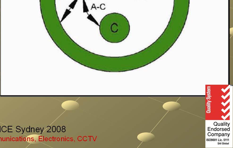
7 Initial Testing. Testing was conducted by REES to determine the impact of various testing connections believed to be in use. Testing was conducted using a model 3 core copper paper insulated lead as per drawing. In reality the outcomes will vary dependant on cable construction, cable length etc. C- E This model typically represents a long cable with an insulation resistance of 60M ohm between phases and between each phase and earth. All resistors are 60M ohm and capacitors are 4uF. Results were extrapolated due to the charge current conditions of the IT used for the testing. Extrapolated voltages of the following various connections are. shown in blue with respect to the system earth.


8 Figure 1. Phase to Phase with NO Earth Reference. Set at 10kV
9 Figure 1. Figure 1, Case Explanation. Extremely Hazardous where the Phase to Phase test set NOT been connected to with the system NO earth. Earth Operators often refer to this as Phase to Phase Reference. Test. In this situation internals of the tester and exposed conductive parts will rise to lethal voltages. The test leads connected Set at to 10KV earth terminal will be exposed to voltages most likely beyond its rating.


10 Figure 2. Phase to Phase with Guard. Set at 10kV
11 Figure 2. Figure 2, Case Explanation. Phase to Phase Regarded as questionable due to the fact that the conductors that are with not under Guard. test are charged to a voltage away from earth. Set at 10kV

12 Figure 3. Phase to Earth with No Jumper Set. Set at 10kV
13 Figure 3. Figure 3, Case Explanation. Phase to Earth Regarded as questionable due to the with fact that No the conductors Jumper that are not under test are charged to a voltage away from earth. Set. Set at 10kV
14 Figure 4. Phase to Phase to Earth with Jumper Set. Set at 10kV
15 Figure 4. Figure 4,Case Explanation. Considered the safest connection method for routine High Voltage Insulation to Earth Testing with of Reticulation Jumper Systems. Set. The following slide will clearly depict the method. Phase to Phase Set at 10kV

16 Recommended Kyoritsu 3124 Testing Connections

17 Recommended Baur PGK25 Testing Connections


18 Simultaneous Phase to Phase and Phase to Earth Test.
19 Testing. Use a discharge stick and ensure that no conductors, other than solidly earthed conductors unless the earth probe or earth hook of a discharge stick is first in contact with the conductor. It is recommended that operators DO NOT rely solely on the internal discharge mechanism of the test equipment. The discharge mechanism may be inoperative. Some insulation testers DO NOT have an inbuilt discharge mechanism. Be Aware of potentially lethal energy levels stored in the capacitance of test specimens. Although most insulation testers have a maximum current of 100uA, the energy stored the energy stored in a test specimen can be lethal.

20 Testing.
21 Testing continued. Regeneration of a DC potential after application and subsequent discharging is not a myth. This phenomemon can readily be demonstrated, any length of healthy PILC cable Ensure the test specimen is left in an earthed state after testing for a period of time at least equal to the test duration. Example: If testing occurred for 5 minutes/phase then all conductors should remain earthed for at least 5 minutes after completion of testing. Ensure that all connectors are securely attached during testing procedures. As a good general practice when HV testing. DO NOT ground yourself either deliberately or inadvertently by touching surrounding conductive equipment such as water pipes, metallic walls of a switch room etc.
22 Batteries & Battery Charger Batteries we have had several units in for repair with AA Alkaline batteries fitted in place of the rechargeable batteries designed for use in this unit. This can cause major problems when the charger is applied to these batteries causing them to vent and spill acid on the main printed circuit board. The slightly higher voltage of alkaline batteries as opposed to rechargeable batteries can also damage the display driver chip creating a relatively expensive repair. The unit is supplied with a universal type battery charger. The fitting is a 2 piece device and if separated can expose terminals. This may expose hazardous voltages if the device is incorrectly connected during testing. Fitting resin lined heat shrink to the plug will prevent separation.

23 Battery Charger..continued
24 Important Observation The colour coding leads connected to various insulation testers vary between manufacturers. All Insulation testers are negative output with respect to ground. Eg. Kyoritsu 3124 has Line output RED (-10KV) Earth lead GREEN Baur PGK25 has HV output BLACK (-25KV) Earth Lead RED
25 Question? Why do Insulation Testers use a Negative Output with respect to Earth?
26 Answer. Although modern insulating materials return insulation resistance readings practically independent of the applied DC voltage, many of the early insulating materials did not. This phenomenon is called electroendosmosis causes older insulating material to exhibit a noticeably higher insulation resistance when the applied voltage is positive with respect to earth. As a result insulation test sets were manufactured with the high voltage output negative with respect to earth so that the worst case reading is obtained. This configuration became very much standard on all insulation testers and high potential test sets and remains the standard configuration for today's insulation measuring instruments.

27 High Voltage Insulation Test Kit
returned to your distributor for attention. 14. Do not operate the function switch while the instrument is connected to a circuit.
 1. This instrument must only be used by a competent and trained person and operated in strict accordance with the instructions. KYORITSU will not accept liability for any damage or injury caused by misuse
Section 3. Test Procedures
 Section 3. Information contained within this section shall be read in conjunction with all sections of this manual Non - Compliant Test Results Where acceptable results are not attained in accordance with
Operator s Manual. PP016 Passive Probe
 Operator s Manual PP016 Passive Probe 2017 Teledyne LeCroy, Inc. All rights reserved. Unauthorized duplication of Teledyne LeCroy documentation materials is strictly prohibited. Customers are permitted
STAFF User Manual. Manual Part #
 STAFF User Manual Manual Part # 030-00085-00 Introduction Congratulations on the purchase of your new STAFF Secondary Fault Locator. The STAFF is specially designed to detect conductor to earth/ground
M.I. Cable High Resistance Fault Locator
 M.I. Cable High Resistance M.I. Cable High Resistance Cable Health and Safety at Work This product, when used in normal or prescribed applications within the parameters specified for mechanical and electrical
GROUNDED ELECTRICAL POWER DISTRIBUTION. Excerpt from Inverter Charger Series Manual BY: VIJAY SHARMA ENGINEER
 GROUNDED ELECTRICAL POWER DISTRIBUTION Excerpt from Inverter Charger Series Manual BY: VIJAY SHARMA ENGINEER .0 Conductors for Electrical Power Distribution For single-phase transmission of AC power or
Model: Pro95 TRUE RMS MILLIAMP CLAMP METER
 Model: Pro95 TRUE RMS MILLIAMP CLAMP METER TABLE OF CONTENTS 1. SAFETY INFORMATION... 1 2. GENERAL SPECIFICATION... 1 3. ELECTRICAL SPECIFICATION... 2 3-1 ACMA MEASUREMENT... 2 3-2 ACA MEASUREMENT...
PHASE ROTATION METER. Operating and Instruction Manual. a n d A C C E S S O R I E S
 PHASE ROTATION METER a n d A C C E S S O R I E S Operating and Instruction Manual HD ELECTRIC COMPANY 1 4 7 5 L A K E S I D E D R I V E WA U K E G A N, I L L I N O I S 6 0 0 8 5 U. S. A. PHONE 847.473.4980
RIGOL. User s Guide. RP1000D Series High Voltage Differential Probe. Feb RIGOL Technologies, Inc
 User s Guide RP1000D Series High Voltage Differential Probe Feb. 2013 RIGOL Technologies, Inc Guaranty and Declaration Copyright 2012 RIGOL Technologies, Inc. All Rights Reserved. Trademark Information
Analog Voltage Detector 1-450kV Operating Instructions VDAO450TM. Patent No. 6,275,022
 Analog Voltage Detector 1-450kV Operating Instructions VDAO450TM Patent No. 6,275,022 CONTENTS Limitation of Warranty and Liability 2 Product Safety Information 3 Design and Function 4 Operating Procedure
ARBE-III Instruction Manual
 ARBE-III Instruction Manual Introduction ARBE-III is a solid state, fully regulated, universal power supply designed specifically for use of pre 1930 s battery operated radios. Three electronically isolated
High Voltage Power Supply EBM30N/XXX SAFETY AND INSTALLATION INSTRUCTIONS
 Tel : +44 (0)1798 877000 Fax : +44 (0)1798 872479 e-mail : hvsales@spellmanhv.co.uk Broomers Park, Broomers Hill Lane Pulborough, W. Sussex, RH20 2RY High Voltage Power Supply EBM30N/XXX SAFETY AND INSTALLATION
FRYCORDER Power Cord Burn-in Generator
 FRYCORDER Power Cord Burn-in Generator Made in USA FRYCORDER Power Cord Burn-in Generator Copyrights & Trademarks Copyright Hagerman Audio Labs 0. All rights reserved. No part of this document may be photocopied,
POWER TRACE TM TASCO, INC.
 POWER TRACE TM Instruction Manual PTL610 TASCO, INC. HOW YOUR POWER TRACE TM OPERATES The Power Trace TM is composed of two primary components: the Receiver and the Transmitter. When the Transmitter is
Agilent U1251B and U1252B Handheld Digital Multimeter. Quick Start Guide
 Agilent U1251B and U1252B Handheld Digital Multimeter Quick Start Guide The following items are included with your multimeter: Silicone test leads 4 mm probes Alligator clips Printed Quick Start Guide
99 Washington Street Melrose, MA Fax TestEquipmentDepot.com # # AAC Clamp Meter. Instruction Manual
 99 Washington Street Melrose, MA 02176 Fax 781-665-0780 TestEquipmentDepot.com #61-732 #61-736 400 AAC Clamp Meter Instruction Manual AC HOLD APO DC KMΩ mva WARNING Read First: Safety Information Understand
Model 4210-MMPC-W. Multi-measurement Prober Cable Kit. Overview
 Model 4210-MMPC-W Keithley Instruments, Inc. Multi-measurement Prober Cable Kit 28775 urora Road Quick Start Guide Cleveland, Ohio 44139 1-888-KEITHLEY http://www.keithley.com Overview The Keithley Instruments
INSTRUCTION MANUAL. Model Autoranging DMM ProbeMeter TM. Measures voltage, resistance, frequency, capacitance, temperature, and duty cycle.
 INSTRUCTION MANUAL Model 403380 Autoranging DMM ProbeMeter TM Measures voltage, resistance, frequency, capacitance, temperature, and duty cycle. Back lit LCD with Autorange and full function displays Audible
GFL3000 Ground Fault Locator Operating Instructions
 GFL3000 Ground Fault Locator Operating Instructions WARNING Read and understand the instructions before operating this unit. Failure to do so could lead to injury or death. The Armada Technologies GFL3000
USER MANUAL. Maxwell Technologies BOOSTCAP Energy Storage Modules. User Manual for 15V Modules: 20 F, 23 F, 53 F, 58 F 15 Volts DC
 USER MANUAL Maxwell Technologies BOOSTCAP Energy Storage Modules User Manual for 15V Modules: 20 F, 23 F, 53 F, 58 F 15 Volts DC BPAK0020 P015 B1 BPAK0023 E015 B1 BPAK0052 P015 B1 BPAK0052 P015 B2 BPAK0058
Broadband Current Probe Series Operation Manual
 Broadband Current Probe Series Operation Manual 1 TABLE OF CONTENTS INTRODUCTION 3 GENERAL INFORMATION 4 OPERATING INSTRUCTIONS 5 FORMULAS 6 MAINTENANCE 7 WARRANTY 8 2 INTRODUCTION CURRENT PROBE SPECIFICATIONS
Model 4210-MMPC-L. Multi-measurement Prober Cable Kit. Overview. Quick start guide topics. Related documents
 Model 0-MMPC-L Keithley Instruments, Inc. Multi-measurement Prober Cable Kit 877 Aurora Road Quick Start Guide Cleveland, Ohio 9-888-KEITHLEY http://www.keithley.com Overview The Keithley Instruments Model
Warning, refer to accompanying documents V CAT II Overvoltage category II device. CSA Canadian Standards Association
 About this Manual To the best of our knowledge and at the time written, the information contained in this document is technically correct and the procedures accurate and adequate to operate this instrument
Digital Voltage Detector 0-999kV Operating Instructions VD1000PTM
 Digital Voltage Detector 0-999kV Operating Instructions VD1000PTM CONTENTS Limitation of Warranty and Liability 2 Product Safety Information 3 Design and Function Battery Replacement 4 Voltage Detection
Dynatel 2250E/2273E Advanced Cable and Fault Locator
 Dynatel 2250E/2273E Advanced Cable and Fault Locator Operators Manual September 1999 78-8097-6500-7-B TABLE OF CONTENTS Introduction... 2 Installing or Replacing the Batteries... 2 Initial Receiver Configuration...
GROUP OF COMPANIES. MERLIN STEALTH Electric Fence Energizer INSTALLERS MANUAL
 GROUP OF COMPANIES MERLIN STEALTH Electric Fence Energizer INSTALLERS MANUAL Revision 1.5 23 February 2007 : INSTALLERS MANUAL Table of Contents 2 INTRODUCTION.. 3 INSTALLER OPTIONS...... 4-11 ALARM SETTING
HIGH VOLTAGE PHASE COMPARATORS
 USER'S MANUAL for HIGH VOLTAGE PHASE COMPARATORS PC Series Double Poles Model System Voltage Full Scale MT6k 6.6kV 8kV MT11k 11kV 12kV MT22k 22kV 24kV MT33k 33kV 36kV MT44k 44kV 48kV Exceeds VDE681-5 /
Equipment Description Quantity as per drawings Actual quantity
 NOTE: SAFETY: Tests must be carried out after the installation, alteration or repair and before putting back to service. At all times maintain suitable clearance to all other electrical equipment and verify
netzerotools.com 374/375/376 Users Manual Clamp Meter
 374/375/376 Clamp Meter Users Manual Fluke 376 True RMS AC DC Clamp Meter Fluke 374 True RMS AC / DC Clamp Meter Fluke 373 True RMS AC Clamp Meter Fluke 375 True RMS AC / DC Clamp Meter LIMITED WARRANTY
INSTRUCTION MANUAL DIGITAL PSC-LOOP TESTER MODEL 4118A KYORITSU ELECTRICAL INSTRUMENTS WORKS,LTD.
 INSTRUCTION MANUAL DIGITAL PSC-LOOP TESTER MODEL 4118A KYORITSU ELECTRICAL INSTRUMENTS WORKS,LTD. CONTENTS 1. SAFE TESTING... 1 2. PROCEDURE OF REMOVING COVER... 4 3. FEATURES... 5 3.1 Instrument Layout...
DOCUMENT OBSOLETE. Dynatel. 2273M Cable/Pipe and Fault Locators 2273M-iD Cable/Pipe/Fault and Marker Locators with id Read/Write
 3 Dynatel 2273M Cable/Pipe and Fault Locators 2273M-iD Cable/Pipe/Fault and Marker Locators with id Read/Write New-to-the-world technology for locating underground utilities without any doubt. The 3M Dynatel
Specifications for 3M Dynatel 2273M/M-iD Cable/Pipe and Fault Locators
 Specifications for 3M Dynatel 2273M/M-iD Cable/Pipe and Fault Locators PHYSICAL SPECIFICATIONS SIZE WEIGHT (H X W X D) IN. (CM) (INCLUDING BATTERIES) Transmitter 6.75 x 11.25 x 7.75 (17.2 x 28.6 x 19.7)
SDCS-03 DISTRIBUTION NETWORK GROUNDING CONSTRUCTION STANDARD (PART-II) OVERHEAD NETWORK GROUNDING. Rev. 01
 OVERHEAD NETWORK GROUNDING. Rev. 01") SEC DISTRIBUTION GROUNDING STANDARD SDCS-03 Part-II Rev.01 SDCS-03 DISTRIBUTION NETWORK GROUNDING CONSTRUCTION STANDARD (PART-II) OVERHEAD NETWORK GROUNDING Rev. 01 This specification is property of SEC
SEC DISTRIBUTION GROUNDING STANDARD SDCS-03 Part-II Rev.01 SDCS-03 DISTRIBUTION NETWORK GROUNDING CONSTRUCTION STANDARD (PART-II) OVERHEAD NETWORK GROUNDING Rev. 01 This specification is property of SEC
User s Guide. RP7000 Series Active Probe. Dec RIGOL Technologies, Inc.
 User s Guide RP7000 Series Active Probe Dec. 2012 RIGOL Technologies, Inc. Guaranty and Declaration Copyright 2011 RIGOL Technologies, Inc. All Rights Reserved. Trademark Information RIGOL is a registered
312, 316, 318. Clamp Meter. Users Manual
 312, 316, 318 Clamp Meter Users Manual PN 1989445 July 2002 Rev.2, 2/06 2002, 2006 Fluke Corporation. All rights reserved. Printed in China. All product names are trademarks of their respective companies.
CURRENT MEARUREMENT SHUNT CS-10/500 USER MANUAL
 CURRENT MEARUREMENT SHUNT CS-10/500 USER MANUAL 2017 Megaimpulse Ltd. Copyright 2017 MEGAIMPULSE Ltd. All Rights Reserved. MEGAIMPULSE LTD. PROVIDES THIS MANUAL "AS IS" WITHOUT WARRANTY OF ANY KIND, EITHER
Model 229 Series 2 Leakage Current Tester OPERATOR S MANUAL
 Model 229 Series 2 Leakage Current Tester OPERATOR S MANUAL SIMPSON ELECTRIC COMPANY 52 Simpson Avenue Lac du Flambeau, WI 54538-99 (715) 588-3311 FAX (715) 588-3326 Printed in U.S.A. Part No. 5-11575
Analog Voltage Detector 0-40kV Operating Instructions VDA040CTM
 Analog Voltage Detector 0-40kV Operating Instructions VDA040CTM CONTENTS Limitation of Warranty and Liability 2 Product Safety Information 3 Design and Function 4 Voltage Detection in the C Position 5-6
Broadband Current Probe Series Operation Manual
 Broadband Current Probe Series Operation Manual 1 TABLE OF CONTENTS WARRANTY 3 INTRODUCTION 4 GENERAL INFORMATION 5 OPERATING INSTRUCTIONS 6 FORMULAS 7 MAINTENANCE 8 2 WARRANTY INFORMATION A.H. Systems
Warning, refer to accompanying documents.
 About this Manual To the best of our knowledge and at the time written, the information contained in this document is technically correct and the procedures accurate and adequate to operate this instrument
DIGITAL CLAMP METER Use s Manual
 MS2026 MS2026R DIGITAL CLAMP METER Use s Manual MS2026 FUNC. RANGE MAX/MIN Hz/% HOLD AC CLAMP METER Auto Range AUTO DC AC MAX MIN REL μnf %Hz kmω mva CAT III 600 V CONTENTS 1. Safety Information...1 1.1
List of Experiments. Exp. # Experiment Title Page #
 List of Experiments Exp. # Experiment Title Page # -- Safety Rules 02 1 Study of High Lab in the University 03 2 To Calibrate a Sphere-Gap using its Breakdown Strength against Gap Settings 07 3 To Calibrate
RAGU 81D DIGITAL MULTIMETER OPERATION MANUAL
 RAGU 81D DIGITAL MULTIMETER OPERATION MANUAL Contents I. General...- 1 - Ⅱ. Open-package Inspection...- 2 - III. Safety Considerations... - 3 - IV.Instrument Panel & Button Function Description...- 9 -
Obsolete Document. Dynatel
 3 Dynatel 2273ME Cable/Pipe and Fault Locators 2273ME-iD Cable/Pipe/Fault and Marker Locators with id Read/Write 2250ME Cable/Pipe Locators 2250ME-iD Cable/Pipe and Marker Locators with id Read/Write New-to-the-world
Keysight 16440A SMU/Pulse Generator Selector
 Keysight 16440A SMU/Pulse Generator Selector User s Guide Notices Keysight Technologies 1994-2014 No part of this manual may be reproduced in any form or by any means (including electronic storage and
G SAFETY WARNINGS. LT300 High current loop tester. User guide
 M LT300 High current loop tester User guide G SAFETY WARNINGS Safety Warnings and Precautions must be read and understood before the instrument is used. They must be observed during use. The earth loop
DM-46 Instruction Manual
 Auto Meter Products Inc. Test Equipment DM-46 Instruction Manual Automotive Multimeter and Inductive Amp Probe The DM-46 is the auto industry s answer to pocket portability in a 20 2650-1552-00 3/8/11
MS2030 CAT III 600 V A V AUTO RS232
 MS2030 AC Digital Clamp Meter User s Manual CAT III 600 V AUTO RS232 A V CONTENTS 1.Introduction...1 2.Safety Information...1 2.1 Precautions...1 2.2 Safety Symbols...3 3. Description...4 3.1 Front Panel...4
T+ and T+ PRO Electrical Tester
 T+ and T+ PRO Electrical Tester Instruction Sheet Introduction The Fluke T+ and T+ PRO Electrical Testers (the Tester ) have the following features: AC and dc voltage measurement, 12 V to 600 V, with or
MaxLite Linear Strip ECO Series
 General Safety Information To reduce the risk of death, personal injury or property damage from fire, electric shock, falling parts, cuts/abrasions, and other hazards read all warnings and instructions
USER'S MANUAL TBM061 TBM062 TBM063 TBM065
 USER'S MANUAL TBM061 TBM062 TBM063 TBM065 Compact AC/DC Clamp-on Multimeter Series 1 1) SAFETY This manual contains information and warnings that must be followed for operating the instrument safely and
USER'S MANUAL ACDC-100 TRMS ACDC-100. Versatile AC/DC Clamp-on Multimeter Series
 99 Washington Street Melrose, MA 02176 Fax 781-665-0780 TestEquipmentDepot.com USER'S MANUAL ACDC-100 TRMS ACDC-100 Versatile AC/DC Clamp-on Multimeter Series 1 1) SAFETY This manual contains information
TAG5000 WIRELESS PHASER. Instruction Manual HD ELECTRIC COMPANY 1475 LAKESIDE DRIVE WAUKEGAN, ILLINOIS U.S.A.
 TAG5000 WIRELESS PHASER Instruction Manual TM HD ELECTRIC COMPANY 1475 LAKESIDE DRIVE WAUKEGAN, ILLINOIS 60085 U.S.A. PHONE 847.473.4980 FAX 847.473.4981 website: www.hdelectriccompany.com DESCRIPTION
CABLE TRACER & PHONE TESTER / GENERATOR
 CABLE TRACER & PHONE TESTER / GENERATOR 183 CB-A Amplifier Probe INSTRUCTION MANUAL Amplifier Probe Amplifier Probe 183 CB-A Figure 1 Amplifier Probe 183 CB-A Figure 2 Features The Amplifier Probe is designed
EI HIGH VOLTAGE INSULATION TESTING POLICY
 Network(s): Summary: ENGINEERING INSTRUCTION EI 09-0001 HIGH VOLTAGE INSULATION TESTING POLICY EPN, LPN, SPN This engineering instruction details the policy for the on-site insulation testing of new and
Agilent U1253B True RMS OLED Multimeter. Quick Start Guide
 Agilent U1253B True RMS OLED Multimeter Quick Start Guide The following items are included with your multimeter: Silicone test leads 4 mm probes Alligator clips Printed Quick Start Guide Rechargeable 8.4
Agilent N2902A 9000 Series Oscilloscope Rack Mount Kit
 Agilent N2902A 9000 Series Oscilloscope Rack Mount Kit Installation Guide Agilent Technologies Notices Agilent Technologies, Inc. 2009 No part of this manual may be reproduced in any form or by any means
SDCS-03 DISTRIBUTION NETWORK GROUNDING CONSTRUCTION STANDARD (PART-I) UNDERGROUND NETWORK GROUNDING. Rev. 01
 UNDERGROUND NETWORK GROUNDING. Rev. 01") SDCS-03 DISTRIBUTION NETWORK GROUNDING CONSTRUCTION STANDARD (PART-I) UNDERGROUND NETWORK GROUNDING Rev. 01 This specification is property of SEC and subject to change or modification without any notice
SDCS-03 DISTRIBUTION NETWORK GROUNDING CONSTRUCTION STANDARD (PART-I) UNDERGROUND NETWORK GROUNDING Rev. 01 This specification is property of SEC and subject to change or modification without any notice
GammaPAT MI 3311 Short instructions Ver. 1.4, Code no
 GammaPAT MI 3311 Short instructions Ver. 1.4, Code no. 20 751 626 Distributor: Manufacturer: METREL d.d. Ljubljanska cesta 77 1354 Horjul Slovenia E-mail: metrel@metrel.si http://www.metrel.si 2010 METREL
MODEL 3810/2 Line Impedance Stabilization Network
 EMC TEST SYSTEMS FEBRUARY 1996 REV C PN 399197 MODEL 3810/2 Line Impedance Stabilization Network OPERATION MANUAL USA P.O. Box 80589 Austin, Texas 78708-0589 2205 Kramer Lane, Austin, Texas 78758-4047
A53106 SERIES DC-TO-DC CONVERTER
 INSTALLATION & MAINTENANCE A53106 SERIES DC-TO-DC CONVERTER AUGUST 2011, REVISED AUGUST 2014 DOCUMENT NO. COM-00-04-20 VERSION C.1 Siemens Industry, Inc., Rail Automation 9568 Archibald Ave., Suite 100,
OPERATOR S INSTRUCTION MANUAL M-2625 AUTO RANGING DIGITAL MULTIMETER
 OPERATOR S INSTRUCTION MANUAL M-2625 AUTO RANGING DIGITAL MULTIMETER with Temperature Probe Copyright 2007 Elenco Electronics, Inc. Contents 1. Safety Information 3,4 2. Safety Symbols 5 3. Front Plate
Blue Point Engineering
 lue Point Engineering Wizard - I Interface oard http://www.pesolutions.com (303) 651.3794 Pointing the Way to Solutions! Talking / Eye Moving Skull Connectors pplication Examples 7805 Eyeball Jar nimatronic
25kV A.C. Electrified Lines - Traction Bonding
 Date:MAR 94 25kV A.C. Electrified Lines - Traction Page 1 of 6 Part A Synopsis This is issued by the to define the Boards requirements for continuity bonding on railway systems. This will ensure a continuous
15B & 17B. Multimeters. Users Manual
 Multimeters Users Manual PN 4228256 July 2012 2012 Fluke Corporation. All rights reserved. Printed in China. Specifications are subject to change without notice. All product names are trademarks of their
Current Probe Fixture Instruction Manual
 Current Probe Fixture Instruction Manual 1 TABLE OF CONTENTS INTRODUCTION 3 GENERAL INFORMATION 4 TEST METHODS 5 SAFETY 7 FIGURES 8 FORMULAS 10 MAINTENANCE 11 WARRANTY 12 2 INTRODUCTION figure 1 Mechanical
Agilent U1273A/U1273AX Handheld Digital Multimeter. Quick Start Guide
 Agilent U1273A/U1273AX Handheld Digital Multimeter Quick Start Guide Verify that you received the following items in the shipment of your multimeter: One pair of red and black test leads One pair of 4
Keysight U1461A Insulation Multimeter/ U1453A Insulation Tester
 Keysight U46A Insulation Multimeter/ U453A Insulation Tester Quick Start Guide Standard Accessories Included In Your Purchase Standard Accessories Included In Your Purchase The following accessories are
E5382B Single-ended Flying Lead Probe Set (for analyzers with 90-pin pod connectors) User Guide
 User Guide") E5382B Single-ended Flying Lead Probe Set (for analyzers with 90-pin pod connectors) User Guide Notices Agilent Technologies, Inc. 2013 No part of this manual may be reproduced in any form or by any means
E5382B Single-ended Flying Lead Probe Set (for analyzers with 90-pin pod connectors) User Guide Notices Agilent Technologies, Inc. 2013 No part of this manual may be reproduced in any form or by any means
374/375/376 Clamp Meter
 374/375/376 Clamp Meter Users Manual PN 3608883 July 2010 2010 Fluke Corporation. All rights reserved. Printed in China. Specifications are subject to change without notice. All product names are trademarks
50 Ω Dummy Load for Transmitter testing and experiments
 50 Ω Dummy Load for Transmitter testing and experiments Many thanks for purchasing this dummy load, it has been designed to provide constant 50 Ω impedance to a radio transmitter to allow off air tests
SKDG Cable Repair Kit Instructions
 SKDG Cable Repair Kit Instructions Description Having to repair your EasyHeat cable is an extremely rare occurrence. Damage is almost always a function of field conditions, such as impacts with tools.
Installation & Operation Manual SAGA1-K Series Industrial Radio Remote Control
 Installation & Operation Manual SAGA1-K Series Industrial Radio Remote Control Gain Electronic Co. Ltd. Table Of Contents Safety Considerations ------------------------------------------------------------2
INSTRUCTIONS FOR USE
 Serial Number: -. ROGOWSKI CURRENT WAVEFORM TRANSDUCERS INSTRUCTIONS FOR USE CWT POWERTEK 148 Beecham Road, Reading Berkshire RG30 2RE United Kingdom Tel: 0118 950 2468 Fax: 0118 958 8360 Email: info@powertekuk.com
N2790A Differential Voltage Probe
 N2790A Differential Voltage Probe User s Guide For Safety, Regulatory, and publishing information, see the pages at the back of this book. Copyright Agilent Technologies 2009 All Rights Reserved. A Contents
Cable testing and diagnostics
 Cable testing and diagnostics To ensure the flow Cost-optimised maintenance through cable diagnostics The sheath and cable testing supports you in assessing whether a cable system is safe and ready to
Keysight Noise Sources: 346C and N4002A (All Serial Numbers) Instructions for Setting Bias Current
 Instructions for Setting Bias Current") Keysight Noise Sources: 346C and N4002A (All Serial Numbers) Instructions for Setting Bias Current Notice: This document contains references to Agilent. Please note that Agilent s Test and Measurement
Keysight Noise Sources: 346C and N4002A (All Serial Numbers) Instructions for Setting Bias Current Notice: This document contains references to Agilent. Please note that Agilent s Test and Measurement
Agilent U1231A/U1232A/U1233A Handheld Multimeter. Quick Start Guide
 Agilent U3A/U3A/U33A Handheld Multimeter Quick Start Guide Verify that you received the following items in the shipment of your multimeter: One pair of red and black test leads Four.5 V AAA alkaline battery
2006 MFJ ENTERPRISES, INC.
 Model MFJ-4416B INSTRUCTION MANUAL CAUTION: Read All Instructions Before Operating Equipment MFJ ENTERPRISES, INC. 300 Industrial Park Road Starkville, MS 39759 USA Tel: 662-323-5869 Fax: 662-323-6551
Advanced Test Equipment Rentals ATEC (2832)
") Established 1981 Advanced Test Equipment Rentals www.atecorp.com 800-404-ATEC (2832) A.H. Systems Model Active Monopole Antennas Active Monopole Antenna Series Operation Manual 1 TABLE OF CONTENTS INTRODUCTION
Established 1981 Advanced Test Equipment Rentals www.atecorp.com 800-404-ATEC (2832) A.H. Systems Model Active Monopole Antennas Active Monopole Antenna Series Operation Manual 1 TABLE OF CONTENTS INTRODUCTION
Blue Point Engineering
 Blue Point Engineering Instruction I www.bpesolutions.com Pointing the Way to Solutions! Puppet - II+ Controller (BPE No. PCA-0001) Servo Position Adjustment EEPROM Digital Button Power 5 Vdc Playback
HTA125A/250A. Power Amplifiers. Installation & Use Manual
 HTA125A/250A Power Amplifiers Installation & Use Manual Specifications subject to change without notice. 2010 Bogen Communications, Inc. All rights reserved. 54-5832-04B 1011 NOTICE: Every effort was made
INSTRUCTION MANUAL. MODEL: Vintage 60R. Vintage Series Guitar Amplifi er
 INSTRUCTION MANUAL MODEL: Vintage 60R Vintage Series Guitar Amplifi er 2 INTRODUCTION Thank you for choosing this Johnson amplifier. Please read this manual carefully and completely before operating your
INSTRUCTIONS FOR USE
 Serial Number: -. ROGOWSKI CURRENT WAVEFORM TRANSDUCERS INSTRUCTIONS FOR USE CWT POWERTEK 148 Beecham Road, Reading Berkshire RG30 2RE United Kingdom Tel: 0118 950 2468 Fax: 0118 958 8360 Email: info@powertekuk.com
Power line detector user manual 1
 index Power line detector user manual 1 index introduction 3 contents 4 safety 5 setup: batteries and antenna 6 setup: antenna 7 installing the Powertec 8 Powertec warning indicators 9 using the Powertec
PARALLEL MULTI-AMP KIT for 7200 Series AMPLIFIERS INSTRUCTION SHEET
 2 5 0 7 W a r r e n S t r e e t, E l k h a r t, I N 4 6 5 1 6 U S A 5 7 4. 2 9 5. 9 4 9 5 w w w. A E T e c h r o n. c o m PARALLEL MULTI-AMP KIT for 7200 Series AMPLIFIERS INSTRUCTION SHEET Kit Contents:
DynatelTM Cable Locator. Operators Manual. October Revision A
 DynatelTM 2210 Cable Locator Operators Manual October 1996 78 8097 5171 8 Revision A 3M TM Dynatel TM 2210 Cable Locator Operators Manual The information in this manual is proprietary to 3M and may not
R-X SERIES. Decade Resistor
 PRECISION INSTRUMENTS FOR TEST AND MEASUREMENT R-X SERIES Decade Resistor User and Service Manual Effectivity: Serial Numbers beginning with P2 RX im/august, 2002 Copyright 2002 IET Labs, Inc. IET LABS,
RIGOL. User s Guide. RP5600 Passive Probe. July 2010 RIGOL Technologies, Inc.
 User s Guide RP5600 Passive Probe July 2010 RIGOL Technologies, Inc. Guaranty and Declaration Copyright 2010 RIGOL Technologies, Inc. All Rights Reserved. Trademark Information RIGOL is a registered trademark
1. General Instructions 2 2. Safety 2 3. Lamp Starting Test Instrument LSTI 5 3
 1. General Instructions 2 2. Safety 2 3. Lamp Starting Test Instrument LSTI 5 3 3.1. Components and Connections of the Front Panel (Fig. 1) 5 3.2. Connection of the Rear Panel (Fig. 2) 7 3.3. Operation
MICROTOOLS MICRONETBLINK KIT
 MICROTOOLS MICRONETBLINK KIT MicroNetBlink TM MicroProbe TM User Guide Manuel Utilisateur Benutzer Handbuch Manuale per l'utente Guía del Usuario Manual do Utilizador 2947-4511-01 Rev. 01 11/01 2001 Fluke
Portable Appliance Testers. OmegaPAT MI 2140 BetaPAT MI 2141 User Manual Ver Code No
 Portable Appliance Testers OmegaPAT MI 2140 BetaPAT MI 2141 User Manual Ver. 1.2. Code No. 20 750 684 Distributor: Producer: METREL d.d. Ljubljanska 77 SI-1354 Horjul E-mail: metrel@metrel.si http://www.metrel.si
Model ST Instruction Manual. True RMS Autoranging Digital Multimeter. reedinstruments. www. com
 Model ST-9933 True RMS Autoranging Digital Multimeter Instruction Manual reedinstruments com Table of Contents Safety... 3 Features... 4 Specifications...4-8 Technical...4-5 Accuracy...5-8 Display Description...
34134A AC/DC DMM Current Probe. User s Guide. Publication number April 2009
 User s Guide Publication number 34134-90001 April 2009 For Safety information, Warranties, Regulatory information, and publishing information, see the pages at the back of this book. Copyright Agilent
EurotestCOMBO MI 3125 / MI 3125E Short instructions Version 2.2, Code no
 EurotestCOMBO MI 3125 / MI 3125E Short instructions Version 2.2, Code no. 20 751 519 Distributor: Manufacturer: METREL d.d. Ljubljanska cesta 77 1354 Horjul Slovenia web site: http://www.metrel.si e-mail:
ROGOWSKI CURRENT WAVEFORM TRANSDUCERS INSTRUCTIONS FOR USE CWT. POWER ELECTRONIC MEASUREMENTS Ltd.
 ROGOWSKI CURRENT WAVEFORM TRANSDUCERS INSTRUCTIONS FOR USE CWT Distributed By: 955 Industrial Road, San Carlos, CA, 94070 USA GMW Associates PHONE: +1 650-802-8292 FAX: +1 650-802-8298 EMAIL: sales@gmw.com
TA MHz oscilloscope probe TA MHz oscilloscope probe
 TA375 100 MHz oscilloscope probe TA386 200 MHz oscilloscope probe User's Guide X1 X10 TA386 X1/X10 Max. 600 Vp Introduction This passive high-impedance oscilloscope probe is suitable for most oscilloscopes
# Digital Multimeter
 #61-797 Digital Multimeter - 1 - TABLE OF CONTENTS 1.Introduction Precautions and Safety Information Symbols Safety 2.Specifications General Specifications Electrical Specifications Required Equipment
Agilent 1160 Series Miniature Passive Oscilloscope Probes. User s Guide
 99 Washington Street Melrose, MA 02176 Phone 781-665-1400 Toll Free 1-800-517-8431 Visit us at www.testequipmentdepot.com Back to the Agilent 1160A Product Info Page User s Guide A Publication number 01160-92009
Keysight U1231A/ U1232A/U1233A Handheld Multimeter. Quick Start Guide
 Keysight UA/ UA/UA Handheld Multimeter Quick Start Guide Contacting Keysight www.keysight.com/find/assist (worldwide contact information for repair and service) Safety and EMC Information This meter is