Rotek AS440 compatible VOLTAGE REGULATOR (AVR)
|
|
|
- Ariel Jordan
- 6 years ago
- Views:
Transcription
1 Rotek AS440 compatible VOLTAGE REGULATOR (AVR) SPECIFICATION INSTALLATION AND ADJUSTMENTS General description Technical specification AS440 is a half wave phase controlled thyristor type AVR and forms part of the excitation system for a brushless generator. The design employs Surface Mount Technology (SMT) for high integration of features in a small footprint AVR. Positive voltage build up from residual levels is ensured by the use of efficient semiconductors in the power circuitry of the AVR. The power and voltage sensing circuits have separate terminals, allowing the excitation power to be derived directly from the stator winding for basic applications or from an auxiliary winding if sustained short circuit performance is required. The AVR is linked with the main stator windings and the exciter field windings to provide closed loop control of the output voltage with load regulation of +/- 1.0%. The AVR voltage sensing terminals continuously sample the output windings for voltage control purposes. In response to this sample voltage, the AVR controls the power fed to the exciter field, and hence the main field, to maintain the machine output voltage within the specified limits, compensating for load, speed, temperature and power factor, of the generator. A frequency measuring circuit continually monitors the generator output and provides under-speed protection of the excitation system, by reducing the output voltage proportionally with speed below a pre-settable threshold. A manual adjustment is provided for factory setting of the under frequency roll off point, (UFRO). This can easily be changed to 50 or 60 Hz in the field by push-on link selection. Over excitation conditions are limited to a safe period by a protection circuit within the AVR. Provision is made for the connection of a remote voltage trimmer, allowing the user fine control of the generator's output. An analogue input is provided allowing connection to the Power Factor controller or other external devices with compatible output. The AVR has the facility for droop CT connection, to allow parallel running with other similarly equipped generators. SENSING INPUT Jumper selectable Vac 1 phase or Vac 1 phase Hz nominal Frequency POWER INPUT V ac 1 phase Frequency Hz nominal OUTPUT 82 V 200 V a.c. Current continuous 4A (see note 1). transient 7.5A for 10 secs. Resistance 15 ohms min (10 ohms min when input volts is less than 175 ac) REGULATION +/- 1.0% (see note 2) THERMAL DRIFT 0.03% per deg. C change in AVR ambient (see note 3) TYPICAL SYSTEM RESPONSE AVR response 20 ms Filed current to 90% 80 ms Machine Volts to 97% 300 ms EXTERNAL VOLTAGE ADJUSTMENT +/-10% with 1 k ohm 1 watt trimmer (see note 4) Increasing resistance lowers voltage. UNDER FREQUENCY PROTECTION Set point 94-98% Hz (see note 5) UNIT POWER DISSIPATION 12 watts maximum BUILD UP VOLTAGE 4 AVR terminals ANALOGUE INPUT Maximum input +/- 5 Vdc (see note 6) Sensitivity Input resistance 1k ohm QUADRATURE DROOP INPUT 10 ohms burden Max. sensitivity: 0.07 A for 5% droop 0PF Max. input: 0.33 A OVER EXCITATION PROTECTION 1V for 5% Generator Volts (adjustable) Set point 65 V dc Time delay seconds (fixed) ENVIRONMENTAL Vibration Hz 50mm/sec 100Hz 2kHz 3.3g Operating temperature -40 to +70C (note 7) Relative Humidity 0-70C 95% (note 8) Storage temperature -55 to +80C NOTES 1. De-rate by 12% if mounted in portrait orientation. 2. With 4% engine governing. 3. After 2 minutes. 4. Generator de-rate may apply. Check with factory. 5. Factory set, semi-sealed, jumper selectable. 6. Any device connected to the analogue input must be fully floating (galvanically isolated from ground), with an insulation strength of 500V ac. 7. De-rate output current by 5% per degree C above 60C. 8. Non condensing.
2 DESIGN DETAIL Sensing Generator Droop Hand Trimmer Potential Divider & Rectifier Low Hz Detection Synchronising Circuit Low Pass Filter Suppression Reference Power supply Short circuit Detector Analogue Input DC Mixer Amp Ramp Generator Level Detector & Driver Power Control Devices Stability Circuit Over excitation detector Exciter Field The main functions of the AVR are: Potential Divider and Rectifier takes a proportion of the generator output voltage and attenuates it. The potential divider is adjustable by the AVR Volts potentiometer and external hand trimmer (when fitted). The output from the droop CT is also added to this signal. A rectifier converts the a.c. input signal into d.c. for further processing. The DC Mixer adds the Analogue input signal the Sensing signal. The Amplifier (Amp) compares the sensing voltage to the Reference and amplifies the difference (error) to provide a controlling signal for the power devices. The Ramp Generator and Level Detector and Driver infinitely control the conduction period of the Power Control Devices and hence provides the excitation system with the required power to maintain the generator voltage within specified limits. The Stability Circuit provides adjustable negative ac feedback to ensure good steady state and transient performance of the control system. The Low Hz Detector measures the period of each electrical cycle and causes the reference voltage to be reduced approximately linearly with speed below a presettable threshold. A Light Emitting Diode gives indication of underspeed running. The Synchronising circuit is used to keep the Ramp Generator and Low Hz Detector locked to the generator waveform period. The Low Pass Filter prevents distorted waveforms affecting the operation of the AVR control circuit. The Short Circuit Detector senses the presence of a short circuit on the generator output and forces the Power Control Devices into full conduction. This only occurs when the AVR is powered from an auxiliary winding. Power Control Devices vary the amount of exciter field current in response to the error signal produced by the Amplifier. Suppression components are included to prevent sub cycle voltage spikes damaging the AVR components and also to reduce the amount of conducted noise on the generator terminals. The Over Excitation Detector continuously monitors the exciter field voltage and provides signals, to collapse the output voltage if an over excitation condition persists for the specified time period. The Power Supply provides the required voltages for the AVR circuitry.
3
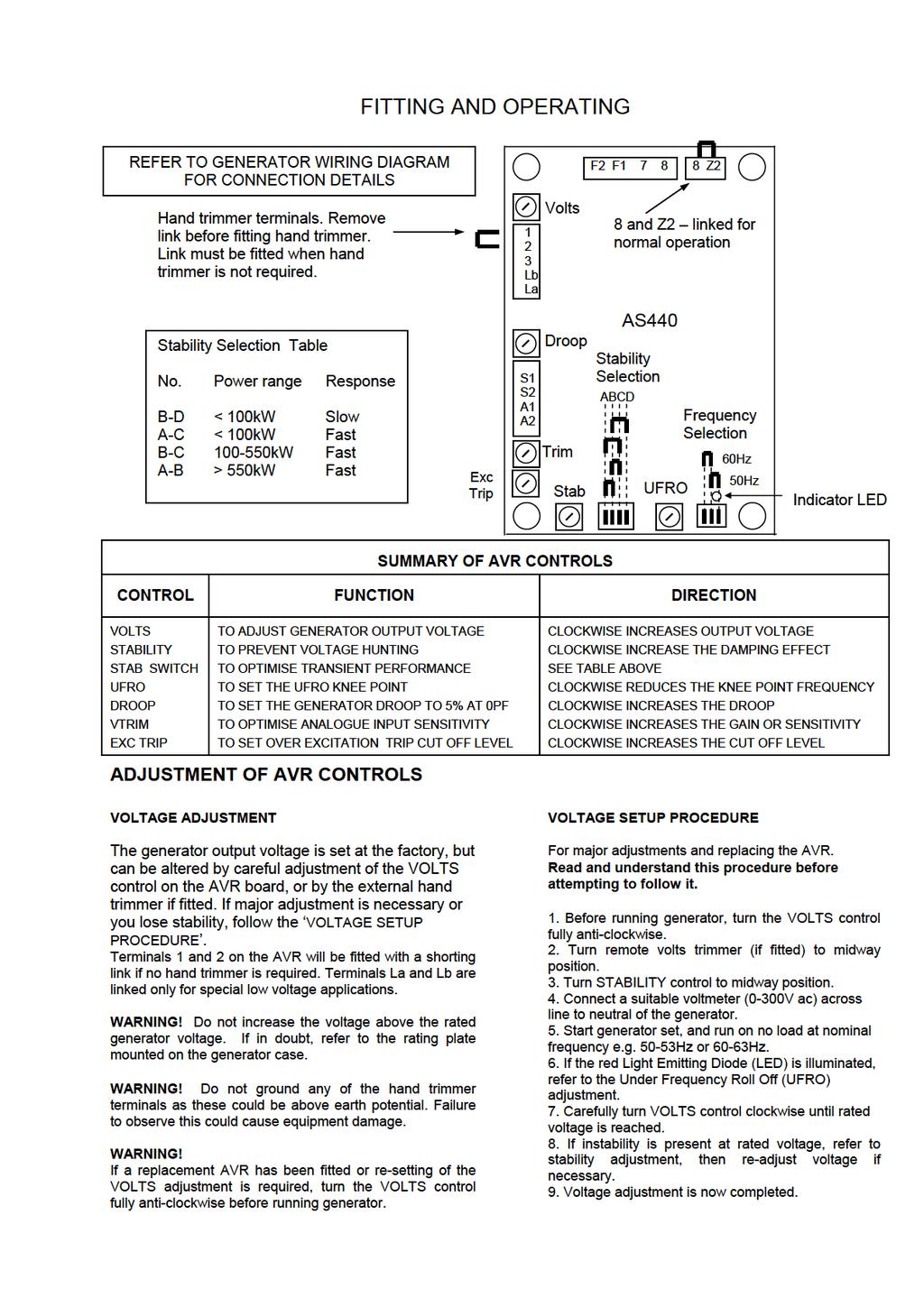
4 FITTING AND OPERATING STABILITY ADJUSTMENT The AVR includes a stability or damping circuit to provide good steady state and transient performance of the generator. A switch is provided to change the response of the stability circuit to suit different frame size generators and applications. The table shows the options available. The slow response settings may prove helpful in reducing lamp flicker. The correct setting of the Stability adjustment can be found by running the generator at no load and slowly turning the stability control anti-clockwise until the generator voltage starts to become unstable. The optimum or critically damped position is slightly clockwise from this point (i.e. where the machine volts are stable but close to the unstable region). UNDER FREQUENCY ROLL OFF (UFRO) ADJUSTMENT The AVR incorporates an underspeed protection circuit which gives a volts/hz characteristic when the generator speed falls below a presettable threshold known as the "knee" point. The red Light Emitting Diode (LED) gives indication that the UFRO circuit is operating. The UFRO adjustment is preset and sealed and only requires the selection of 50/60Hz using the jumper link. For optimum setting, the LED should illuminate as the frequency falls just below nominal, i.e. 47Hz on a 50Hz system or 57Hz on a 60Hz system. DROOP ADJUSTMENT Generators intended for parallel operation are fitted with a quadrature droop C.T. which provides a power factor dependent signal for the AVR. The C.T. is connected to S1, S2 on the AVR. The DROOP adjustment is normally preset in the works to give 5% voltage droop at full load zero power factor. Clockwise increases the amount of C.T. signal injected into the AVR and increases the droop with lagging power factor (cos Ø). With the control fully anti-clockwise there is no droop. TRIM ADJUSTMENT An analogue input (A1 A2) is provided to connect to a Power Factor Controller or other devices. It is designed to accept dc signals up to +/- 5 volts. WARNING! Any devices connected to this input must be fully floating and galvanically isolated from ground, with an insulation capability of 500 Vac. Failure to observe this could result in equipment damage. The dc signal applied to this input adds to the AVR sensing circuit. A1 is connected to the AVR 0 volts. Positive on A2 increases excitation. Negative on A2 decreases excitation. The TRIM control allows the user to adjust the sensitivity of the input. With TRIM fully anti-clockwise the externally applied signal has no effect. Clockwise it has maximum effect. Normal setting is fully clockwise when used with a Power Factor Controller. OVER EXCITATION (EXC TRIP) ADJUSTMENT The adjustment is set and sealed in the works and should not be altered. An over excitation condition is indicated on the common LED which also indicates under speed running. The generator must be stopped to reset an over excitation condition. ISOLATING THE EXCITATION CIRCUIT In some applications it is desirable to isolate the excitation circuit. There are two different ways of doing this depending on the AVR connection to the generator stator. The modifications mentioned below must be done with the generator at rest. If the AVR is fitted with a link across the 2 way terminal block Z2 & 8, then the AVR power circuit is connected to the main stator winding. In this case a switch with a Nominal rating of 240vac 10 Amps can be connected across the AVR terminals Z2 & 8 after removing the link. When the switch is open, the excitation circuit is isolated. The link should be kept for future use if required. If the AVR has a wire connected to terminal Z2 (wire labeled Z2), then the AVR power circuit is connected to an auxiliary winding. In this case a switch with a nominal rating of 240vac 10 Amps can be connected in series with the wire Z2. When the switch is open, the excitation circuit is isolated
5
AS440 AUTOMATIC VOLTAGE REGULATOR (AVR)
") AS440 AUTOMATIC VOLTAGE REGULATOR (AVR) SPECIFICATION INSTALLATION AND ADJUSTMENTS General description Technical specification AS440 is a half wave phase controlled thyristor type AVR and forms part of
AS440 AUTOMATIC VOLTAGE REGULATOR (AVR) SPECIFICATION INSTALLATION AND ADJUSTMENTS General description Technical specification AS440 is a half wave phase controlled thyristor type AVR and forms part of
SPECIFICATION, CONTROLS AND ACCESSORIES
 AS440 Automatic Voltage Regulator (AVR) SPECIFICATION, CONTROLS AND ACCESSORIES English Original Instructions A043Y697 (Issue 2) Table of Contents 1. DESCRIPTION... 1 2. SPECIFICATION... 3 3. CONTROLS...
SPECIFICATION, CONTROLS AND ACCESSORIES
 AS540 Automatic Voltage Regulator (AVR) SPECIFICATION, CONTROLS AND ACCESSORIES English Original Instructions A054N491 (Issue 1) Table of Contents 1. DESCRIPTION... 1 2. SPECIFICATION... 3 3. CONTROLS...
PI144H - Winding 311 APPROVED DOCUMENT. Technical Data Sheet
 PI144H - Winding 311 Technical Data Sheet PI144H SPECIFICATIONS & OPTIONS STANDARDS Stamford industrial generators meet the requirements of BS EN 60034 and the relevant section of other international standards
SPECIFICATION, CONTROLS AND ACCESSORIES
 MX341 Automatic Voltage Regulator (AVR) SPECIFICATION, CONTROLS AND ACCESSORIES English Original Instructions A043Y699 (Issue 2) Table of Contents 1. DESCRIPTION... 1 2. SPECIFICATION... 3 3. CONTROLS...
R1 Q2 Q1 F2 F1 N A1 A2 FUSE V AC S UF OE SL UF OE R150 R150. AVRs. Installation and maintenance
 Droop R2 R1 Q2 Q1 F2 F1 N W V A1 A2 FUSE V AC S UF OE SL UF OE 50 Hz 60 Hz This manual concerns the alternator AVR which you have just purchased. We wish to draw your attention to the contents of this
R180. AVRs. Installation and maintenance
 This manual concerns the alternator AVR which you have just purchased. We wish to draw your attention to the contents of this maintenance manual. SAFETY MEASURES Before using your machine for the first
VOLTAGE REGULATOR R 449. Installation and maintenance. This manual must be sent to the end user R 449 X2 Z1 X1 Z2 E+ E- (12V - 10A)
") This manual must be sent to the end user X2 Z1 X1 Z2 E+ E- J1 t (12V - 10A) ~ 10 ohms Exciter field + - Isolated DC power supply Installation and maintenance WARNING TO AVOID HARM EITHER TO PEOPLE OR TO
This manual must be sent to the end user X2 Z1 X1 Z2 E+ E- J1 t (12V - 10A) ~ 10 ohms Exciter field + - Isolated DC power supply Installation and maintenance WARNING TO AVOID HARM EITHER TO PEOPLE OR TO
GX 340 SERIES (AUTOMATIC VOLTAGE REGULATOR)
") GX 340 SERIES (AUTOMATIC VOLTAGE REGULATOR) Email Address: info@powersystems.com.au Web Page: http://www.powersystems.com.au This AVR will replace the following Stamford Part Nos. And many more 350 28700
GX 340 SERIES (AUTOMATIC VOLTAGE REGULATOR) Email Address: info@powersystems.com.au Web Page: http://www.powersystems.com.au This AVR will replace the following Stamford Part Nos. And many more 350 28700
R448 & R448 V50 A.V.R. Installation and maintenance R 448 ST5 ST3 ST10. Armature + 6- Field X2 Z1 X1 Z2 E+ E- 0V Slow fuse 250V 10 A
 Armature + 6- Field Thismanualistobegivento theenduser F1 ST5 Slow fuse 250V 10 A with LAM without LAM 10 Yellow 11 Red 12 Black 9 Green X2 Z1 X1 Z2 E+ E- 0V 110 22 ST3 requency 50Hz 60Hz ST10 R 448 This
Using the VR448 in place of the Marathon DVR 2000
 Using the 448 in place of the Marathon D 2000 D2000E (digital A) provides 7.5A 150VDC Max output short time in compareson to model EA448 (Analog A) thats provide 10 A 160VDC Max output short time Both
WDG 12 - Technical Data Sheet
 LV 804 T WDG 12 - Technical Data Sheet FRAME LV 804 T SPECIFICATIONS & OPTIONS STANDARDS Cummins Generator Technologies industrial generators meet the requirements of BS EN 60034 and the relevant sections
McPherson Voltage Regulators 4501 NW 27 Ave Miami FL
 McPherson Voltage Regulators 4501 NW 27 Ave Miami FL 33142 305-634-1511 To avoid of possible personal injury or equipment damage read and understand this manual before installation. (A.V.R) 208 / 380 /
R1 Q2 Q1 F2 F1 N A1 A2 FUSE V AC S UF OE SL UF OE R150 A.V.R. R150. Installation and maintenance
 Droop R2 R1 Q2 Q1 F2 F1 N W V A1 A2 FUSE V AC S UF OE SL UF OE 50 Hz 60 Hz This manual concerns the alternator which you have just purchased. We wish to draw your attention to the contents of this maintenance
WDG 71 - Technical Data Sheet
 HV 804 R WDG 71 - Technical Data Sheet FRAME HV 804 R SPECIFICATIONS & OPTIONS STANDARDS Cummins Generator Technologies industrial generators meet the requirements of BS EN 60034 and the relevant sections
R438 A.V.R. Installation and maintenance. This manual is to be given to. the end user CALL US TODAY POWER-58. SHOP ONLINE
 T1 T7 T2 T8 This manual is to be given to the end user T4 T10 140 mm T5 T11 X2 Z1X1 Z2 E+ E- 0V 110 220 380 200 mm z P1 ST9 AREP PMG This manual concerns the alternator which you have just purchased. We
WDG 12 - Technical Data Sheet
 LV 804 S WDG 12 - Technical Data Sheet FRAME LV 804 S SPECIFICATIONS & OPTIONS STANDARDS Cummins Generator Technologies industrial generators meet the requirements of BS EN 60034 and the relevant sections
WDG 07 - Technical Data Sheet
 LV 804 S WDG 07 - Technical Data Sheet FRAME LV 804 S SPECIFICATIONS & OPTIONS STANDARDS Cummins Generator Technologies industrial generators meet the requirements of BS EN 60034 and the relevant sections
WDG 12 - Technical Data Sheet
 LV 804 W WDG 12 - Technical Data Sheet FRAME LV 804 W SPECIFICATIONS & OPTIONS STANDARDS STAMFORD AC generators are designed to meet the performance requirements of IEC EN 60034-1. Other international
WDG 12 - Technical Data Sheet
 LV 804 R WDG 12 - Technical Data Sheet FRAME LV 804 R SPECIFICATIONS & OPTIONS STANDARDS STAMFORD AC generators are designed to meet the performance requirements of IEC EN 60034-1. Other international
WDG 13 - Technical Data Sheet
 LV 804 T WDG 13 - Technical Data Sheet FRAME LV 804 T SPECIFICATIONS & OPTIONS STANDARDS Cummins Generator Technologies industrial generators meet the requirements of BS EN 60034 and the relevant sections
WDG 61 - Technical Data Sheet
 HV 804 W WDG 61 - Technical Data Sheet FRAME HV 804 W SPECIFICATIONS & OPTIONS STANDARDS STAMFORD AC generators are designed to meet the performance requirements of IEC EN 60034-1. Other international
WDG 51 - Technical Data Sheet
 MV 804 S WDG 51 - Technical Data Sheet FRAME MV 804 S SPECIFICATIONS & OPTIONS STANDARDS STAMFORD AC generators are designed to meet the performance requirements of IEC EN 60034-1. Other international
WDG 83 - Technical Data Sheet
 HV 804 R WDG 83 - Technical Data Sheet FRAME HV 804 R SPECIFICATIONS & OPTIONS STANDARDS STAMFORD AC generators are designed to meet the performance requirements of IEC EN 60034-1. Other international
ADVR-053. Hybrid Universal Analog Digital Voltage Regulator Operation Manual
 ADVR-053 Hybrid Universal Analog Digital Voltage Regulator Operation Manual Self Excited 5 Amp Analog/Digital Voltage Regulator For shunt and auxiliary windings generators With over-excitation and lost
GX 600 SERIES (AUTOMATIC VOLTAGE REGULATOR)
") GX 600 SERIES (AUTOMATIC VOLTAGE REGULATOR) Email Address: info@powersystems.com.au Web Page: http://www.powersystems.com.au This AVR will replace the following Stamford Part Nos. And many more Series
GX 600 SERIES (AUTOMATIC VOLTAGE REGULATOR) Email Address: info@powersystems.com.au Web Page: http://www.powersystems.com.au This AVR will replace the following Stamford Part Nos. And many more Series
V S UF OPEN IN 60Hz OE UF SL R120 V N1 U N F1 F2 A.V.R. R120. Installation and maintenance
 V S UF OPEN IN 60Hz OE UF SL V N1 U N F1 F2 This manual concerns the alternator which you have just purchased. We wish to draw your attention to the contents of this maintenance manual. SAFETY MEASURES
DLVP A OPERATOR S MANUAL
 DLVP-50-300-3000A OPERATOR S MANUAL DYNALOAD DIVISION 36 NEWBURGH RD. HACKETTSTOWN, NJ 07840 PHONE (908) 850-5088 FAX (908) 908-0679 TABLE OF CONTENTS INTRODUCTION...3 SPECIFICATIONS...5 MODE SELECTOR
EVC600C User Manual EVC600C SERIES. EVC600C User Manual. Date Version Note. Version. Page 1 of 6. Ver 1.
 Ver 1.0 Date: 2014/07/31 EVC600C SERIES Version Date Version Note 2014-07-31 1.0 Original release http://www.engga.com.cn Page 1 of 6 Introduction EVC600C Automatic Voltage Regulator(AVR)is alternator
R438 A.V.R. R438. Installation and maintenance X2 Z1 X1 Z2 E+ E- 0V REQUEST A QUOTE
 X2 Z1 X1 Z2 E+ E- 0V 110 220 380 This manual concerns the alternator which you have just purchased. We wish to draw your attention to the contents of this maintenance manual. SAFETY MEASURES Before using
R448 & R448 V50 A.V.R.
 Armature + 6- This manual is to be given to the end user F1 ST5 Field Slow fuse 250V 10 A with LAM without LAM 10 Yellow 11 Red 12 Black 9 Green X2 Z1 X1 Z2 E+ E- 0V 110 22 ST3 requency 50Hz 60Hz LAM 13
PI734F - Winding 28. Technical Data Sheet APPROVED DOCUMENT
 - Winding 28 Technical Data Sheet SPECIFICATIONS & OPTIONS STANDARDS Stamford industrial generators meet the requirements of BS EN 60034 and the relevant sections of other national and international standards
Thornwood Drive Operating Manual: Two-SCR General Purpose Gate Firing Board FCRO2100 Revision H
 http://www.enerpro-inc.com info@enerpro-inc.com 5780 Thornwood Drive Report R188 Goleta, California 93117 February 2011 Operating Manual: Two-SCR General Purpose Gate Firing Board FCRO2100 Revision H Introduction
PI734F - Winding 07. Technical Data Sheet APPROVED DOCUMENT
 - Winding 07 Technical Data Sheet SPECIFICATIONS & OPTIONS STANDARDS Stamford industrial generators meet the requirements of BS EN 34 and the relevant sections of other national and international standards
PI734E - Winding 312. Technical Data Sheet APPROVED DOCUMENT
 - Winding 312 Technical Data Sheet SPECIFICATIONS & OPTIONS STANDARDS Stamford industrial generators meet the requirements of BS EN 60034 and the relevant sections of other national and international standards
PI734C - Winding 312. Technical Data Sheet APPROVED DOCUMENT
 - Winding 312 Technical Data Sheet SPECIFICATIONS & OPTIONS STANDARDS Stamford industrial generators meet the requirements of BS EN 60034 and the relevant sections of other national and international standards
PI734B - Winding 312. Technical Data Sheet APPROVED DOCUMENT
 - Winding 312 Technical Data Sheet SPECIFICATIONS & OPTIONS STANDARDS Stamford industrial generators meet the requirements of BS EN 60034 and the relevant sections of other national and international standards
PI734C - Technical Data Sheet
 PI734C - Technical Data Sheet PI734C SPECIFICATIONS & OPTIONS STANDARDS Newage Stamford industrial generators meet the requirements of BS EN 60034 and the relevant sections of other national and international
PI734A - Technical Data Sheet
 PI734A - Technical Data Sheet PI734A SPECIFICATIONS & OPTIONS STANDARDS Newage Stamford industrial generators meet the requirements of BS EN 60034 and the relevant sections of other national and international
PM734D - Winding 312. Technical Data Sheet APPROVED DOCUMENT. Generator Solutions AS
 PM734D - Winding 312 Technical Data Sheet PM734D SPECIFICATIONS & OPTIONS STANDARDS Marine generators may be certified to Lloyds, DnV, Bureau Veritas, ABS, Germanischer-Lloyd or RINA. Other standards and
PM734F - Winding 312. Technical Data Sheet APPROVED DOCUMENT
 PM734F - Winding 312 Technical Data Sheet PM734F SPECIFICATIONS & OPTIONS STANDARDS Marine generators may be certified to Lloyds, DnV, Bureau Veritas, ABS, Germanischer-Lloyd or RINA. Other standards and
M40FA640A/A - Mark I. User Manual SIN.NT Automatic Voltage Regulator for Three-phase Synchronous Generators. (Issued: 04.
 M40FA640A/A - Mark I User Manual Automatic Voltage Regulator for Three-phase Synchronous Generators (Issued: 04.2010) SIN.NT.015.6 Instruction Manual Installation Operation Maintenance MARELLI AVR M40FA640A
PM734B - Technical Data Sheet. Generator Solutions AS
 - Technical Data Sheet STANDARDS Marine generators may be certified to Lloyds, DnV, Bureau Veritas, ABS, Germanischer-Lloyd or RINA. Other standards and certifications can be considered on request. DESCRIPTION
Instructions AVC125-10: Voltage Regulator. Voltage Range. Maximum Continuous Burden. Voltage Range. Nominal Frequency
 www.basler.com + 68.654.234 (USA) info@basler.com Model Description AVC25-0 Voltage Regulator INTRODUCTION The AVC63-2 and AVC25-0 regulate the level of excitation supplied to the field of a conventional,
Ametek, Inc. Rotron Technical Products Division. 100 East Erie St., Suite 200 Kent, Ohio User's Guide. Number Revision F
 Ametek, Inc. Rotron Technical Products Division 100 East Erie St., Suite 200 Kent, Ohio 44240 User's 120 Volt, 800 Watt and 240 Volt, 1200 Watt Brushless Motor Drive Electronics 5.7" (145 mm) and 7.2"
WATT TRANSDUCER. Instruction Manual
 WT 9200 WATT TRANSDUCER Instruction Manual IM-2 September 2003 USA: 6428 Ridglea Drive, Watauga, Texas 76148 Tel/Fax 1-817-427-2060/2067 E-mail: wes@westecinstruments.com SPECIFICATIONS Power Supply Input
ADVR-16. Hybrid Universal Analog Digital Voltage Regulator Operation Manual. Self Excited 16 Amp Analog / Digital Voltage Regulator
 ADV-16 Hybrid Universal Analog Digital Voltage egulator Operation Manual elf Excited 16 Amp Analog / Digital Voltage egulator for use in 170 ~ 510 VAC brushless generators with paralleling compatibility
EA05A. Generator Automatic Voltage Regulator Operation Manual. Self Excited Automatic Voltage Regulator 5 Amp AVR For General Generators
 EA05A Generator Automatic egulator Operation Manual elf Excited Automatic egulator 5 Amp AV For General Generators Headquarters : o., Lane 01, Chien Fu., Chyan Jenn Dist., Kaohsiung, AIWA el : + 886-7-811771
PRODUCT / TEST MANUAL 2V162K4 VOLTAGE REGULATOR RELAY
 Sheet 1 of 12 TEST DATE CUSTOMER SERIAL No OLTC ACKNOWLEDGE SETUP AUTOMATIC or FEEDBACK CONTROL PRODUCT / TEST MANUAL 2V162K4 VOLTAGE REGULATOR RELAY Issue Date Level I 21/05/1998 Initial issue. Summary
GTT 25A - 40A - 60A - 90A - 120A POWER SOLID STATE RELAYS WITH ANALOG CONTROL
 GTT 25A - 40A - 60A - 90A - 120A POWER SOLID STATE RELAYS WITH ANALOG CONTROL Main applications Plastics extrusion lines and injection moulding machines Polymerization plant for synthetic fibre production
1. SUMMARY 2. SPECIFICATION 3. WIRING. 3.3 Power Input Voltage Selection. 3.1 A to C: Sensing Input. 3.2 B to C: Power Input
 Hybrid Universal Analog/Digital 7 Amp Voltage egulator with over-excitation and lost of sensing Proteccion with Provision for Power Input from an auxiliary winding Operations Manual 1. UMMAY he ADV-073
ENGINE GOVERNING SYSTEMS LSM200 SERIES LOAD SHARING MODULE. GOVERNORS AMERICA CORP. 720 Silver Street Agawam, MA , USA MEMBER
 ENGINE GOVERNING SYSTEMS LSM200 SERIES LOAD SHARING MODULE MEMBER GOVERNORS AMERICA CORP. 720 Silver Street Agawam, MA 01001-2907, USA LSM200 SERIES LOAD SHARING MODULE PRODUCT TECHNICAL INFORMATION PTI
815-BR SERVO AMPLIFIER FOR BRUSH SERVOMOTORS
 815-BR SERVO AMPLIFIER FOR BRUSH SERVOMOTORS USER GUIDE September 2004 Important Notice This document is subject to the following conditions and restrictions: This document contains proprietary information
ADVR-2100M. Universal Hybrid Analog-Digital Voltage Regulator Operation Manual
 ADV-2100M Universal Hybrid Analog-Digital Voltage egulator Operation Manual Hybrid Universal Analog / Digital 1 or 3 Phase 5 Amp elf Excited, hunt, Auxiliary Winding, Harmonic Power or PMG Automatic Voltage
R 450. AVRs. Installation and maintenance. This manual is to be given to. the end user R 450 VOLT. STAB. I EXC STAT. LEDS PMG
 6 5 4 7 8 9 C US 45 en -. / e 5 Hz EXT FREQ 6 Hz SETTING This manual is to be given to the end user VOLT. STAB. I EXC FUSIBLES / FUSES EXT.FREQ. SET. ON ONLY FOR SPECIAL CONFIG. KNEE 5Hz 65Hz 6Hz PHASE
ADVR-053. Hybrid Universal Analog Digital Voltage Regulator Operation Manual
 ADV-053 Hybrid Universal Analog Digital Voltage egulator Operation Manual elf Excited 5 Amp Analog / Digital Voltage egulator For shunt and auxiliary windings generators With over-excitation and lost of
r 450 Installation and maintenance This manual is to be given to the end user R 450 VOLT. STAB. I EXC STAT. AREP PMG FUSIBLES / FUSES
 8 7 9 6 5 4 C 45 en -. / a R 45 DETECT. PH PH. SENSING 5 Hz EXT FREQ 6 Hz SETTING This manual is to be given to the end user VOLT. STAB. I EXC FUSIBLES / FUSES EXT.FREQ. SET. ON ONLY FOR SPECIAL CONFIG.
1525-BRS INFORMATION MANUAL SERV O D YN A M ICS. D y n ad r iv e Ave Crocker Suite 10 Valencia, CA
 28231 Ave Crocker Suite 10 Valencia, CA 91355 818-700-8600 Servodynamics.com INFORMATION MANUAL 1525-BRS SERV O D YN A M ICS U SA www.servodynamics.com D y n ad r iv e Bru sh INDEX Page INTRODUCTION 2
RISH EM 3490 SS Kilowatt Hour Energy Meter With Rs485 RISH EM 3490 SS. Application : Product Features: Indication: Pulse Indication:
 Application : RISH Master 3490 SS is a 96mm x 96mm panel mounted kilowatt hour meter it measures active energy with class 1.0 accuracy having auto-resetting 8 digit seven segment LED counter. The unit
Excitation systems and automatic voltage regulators
 ELEC0047 - Power system dynamics, control and stability Excitation systems and automatic voltage regulators Thierry Van Cutsem t.vancutsem@ulg.ac.be www.montefiore.ulg.ac.be/~vct November 2017 1 / 16 Overview
MODEL 421 Over/Under Motor Load Monitor
 MODEL 421 Over/Under Motor Load Monitor Monitors True Motor Power (volts x current x power factor) Detects Motor Overload or Underload Operates on 120 or, Single-phase or 3-phase Built-in Trip and Restart
KWM-2/2A Transceiver THE COLLINS KWM-2/2A TRANSCEIVER
 KWM-2/2A Transceiver Click the photo to see a larger photo Click "Back" button on browser to return Courtesy of Norm - WA3KEY THE COLLINS KWM-2/2A TRANSCEIVER Unmatched for versatility, dependability and
TOSHIBA International Corp
 TOSHIBA International Corp GUIDE SPECIFICATIONS THREE PHASE UNINTERRUPTIBLE POWER SYSTEM TOSHIBA 4200FA 30 kva CT Internal Battery UPS GUIDE SPECIFICATIONS 1 (30 kva CT) 1.0 SCOPE 1.1 System This specification
CAT BOARD A CONTROL AND TRIGGER BOARD FOR 3-PHASE POWER SUPPLIES
 CAT BOARD A3-290605 CONTROL AND TRIGGER BOARD FOR 3-PHASE POWER SUPPLIES Dynapower/Rapid Power Corporation 85 Meadowland Drive South Burlington, Vermont 05403 Phone: 802-860-7200 Fax: 802-864-3782 Toll
D I G I T A L V O L T A G E R E G U L A T O R
 The Cat Digital Voltage Regulator is a microprocessor based control designed to provide precise voltage control, robust transient response, and generator protection with industry leading features and versatility.
LM565/LM565C Phase Locked Loop
 LM565/LM565C Phase Locked Loop General Description The LM565 and LM565C are general purpose phase locked loops containing a stable, highly linear voltage controlled oscillator for low distortion FM demodulation,
DynaDrive INFORMATION MANUAL SDFP(S)
") DynaDrive INFORMATION MANUAL SDFP(S)1525-17 SERVO DYNAMICS CORP. 28231 Avenue Crocker, Santa Clarita, CA. 91355 (818) 700-8600 Fax (818) 718-6719 www.servodynamics.com INDEX Page INTRODUCTION 2 ELECTRICAL
DynaDrive INFORMATION MANUAL SDFP(S)1525-17 SERVO DYNAMICS CORP. 28231 Avenue Crocker, Santa Clarita, CA. 91355 (818) 700-8600 Fax (818) 718-6719 www.servodynamics.com INDEX Page INTRODUCTION 2 ELECTRICAL
Thornwood Drive Operating Manual: Six-SCR General Purpose Gate Firing Board FCOG6100 Revision R
 http://www.enerpro-inc.com info@enerpro-inc.com 5780 Thornwood Drive Report R380 Goleta, California 93117 June 2008 Operating Manual: Six-SCR General Purpose Gate Firing Board FCOG6100 Revision R Introduction
Phoenix DX Clean Power (18 Pulse) AC Drive
 AC Drive") PHOENIX DX Phoenix DX Clean Power (18 Pulse) AC Drive Poor power quality can be costly. Nonlinear loads, including AC Drives, introduce undesirable harmonic currents into the power system that can damage
PHOENIX DX Phoenix DX Clean Power (18 Pulse) AC Drive Poor power quality can be costly. Nonlinear loads, including AC Drives, introduce undesirable harmonic currents into the power system that can damage
SRVODRV REV7 INSTALLATION NOTES
 SRVODRV-8020 -REV7 INSTALLATION NOTES Thank you for purchasing the SRVODRV -8020 drive. The SRVODRV -8020 DC servo drive is warranted to be free of manufacturing defects for 1 year from the date of purchase.
AGN 124 AVR Power Supplies
 Application Guidance Notes: Technical Information from Cummins Generator Technologies AGN 124 AVR Power Supplies DESCRIPTION The simplest way to provide a power supply for an AVR is to take power directly
M16FA655A - Mark V. User Manual SIN.NT Automatic Voltage Regulator for Three-phase Synchronous Generators
 M16FA655A - Mark V User Manual Automatic Voltage Regulator for Three-phase Synchronous Generators SIN.NT.002.5 Instruction Manual Installation Operation Maintenance MARELLI AVR M16FA655A hanada technolgoy
Power-Tronics, Inc. Electronic Voltage Regulators and Static Exciters P.O. Box , Kerrville, Texas 78029
 Power-Tronics, Inc. Electronic Voltage Regulators and Static Exciters P.O. Box 291509, Kerrville, Texas 78029 Phone: 830.895.4700 Fax: 830.895.4703 Email: pwrtron@power-tronics.com Web: www.power-tronics.com
Low Voltage alternators - 4 pole LSA 47.2
 Low Voltage alternators - 4 pole 36 to 6 kva - Hz / 46 to 7 kva - 6 Hz Electrical and mechanical data 3782 en - 214.1 / h 36 to 6 kva - Hz / 46 to 7 kva - 6 Hz SPECIALLY ADAPTED TO APPLICATIONS The alternator
Product Data Sheet. Models 1022/1025/1029C/1032/3629B 3629B. Models 1022/1025/1032. Model 1029C. Model 3629B. Phase Angle Power Control
 s 1022/1025/1029C/1032/3629B 3629B Product Data Sheet s 1022/1025/1032 Single phase power controllers Current ratings from 10 to 70 Amps 1022-0 to 5VDC or pot input 1025-4 to 20 ma signal 1032 Current
10. High Boost HAM. Maxi, Mini, Micro Design Guide Rev 4.9 vicorpower.com
 THE HIGH-BOOST HARMONIC ATTENUATOR MODULE COMPATIBLE WITH V375, VI-26x AND VI-J6x FAMILIES The High-Boost Harmonic Attenuation Module (HAM) consists of a full-wave rectifier, a high-frequency zerocurrent-switching
CAP6637A AC-DC Open Loop Converter
 Description: The CAP6637 is a three-phase AC to DC Converter assembly. The assembly includes the three-phase SCR converter bridge, a free wheeling diode, the thermal management system, a BAP1950 SCR phase
Generator AutomaticVoltageRegulator OperationManual
 Generator AutomaticVoltageegulator OperationManual uitable for use on single and three phase selfexcited brushless generators Compatible with Mecc Alte* U* & 7* A ot a genuine Mecc Alti * regulator ame
Conic Systems Inc. INSTRUCTION MANUAL FOR DATATRAN C2547 UNIVERSAL AMPLIFIER MODULE
 Conic Systems Inc. INSTRUCTION MANUAL FOR DATATRAN C2547 UNIVERSAL AMPLIFIER MODULE FOR TECHNICAL OR SALES ASSISTANCE CONTACT CONIC SYSTEMS INC. AT TEL: 845.856.4313 OR FAX: 845.858.2824 EMAIL: INFO@CONICSYSTEMS.COM
AGN 124 AVR Power Supplies
 Application Guidance Notes: Technical Information from Cummins Generator Technologies AGN 124 AVR Power Supplies DESCRIPTION The simplest way to provide a power supply for an AVR is to take power directly
A.V.R. R250. Installation and maintenance R250 0V E+ E- VOLT STAB FREQ. & L.A.M. CONFIG. REQUEST A QUOTE
 110 0V E+ E- VOLT STAB KNEE 47.5Hz OFF 9 SPECIAL 8 KNEE 65Hz 7 OFF KNEE 6 57Hz OFF 7 8 50Hz o 9 0 5 6 1 2 3 4 OFF 1 13% 2 25% 3 OFF 4 13% 5 25% 60Hz FREQ. & L.A.M. CONFIG. This manual concerns the alternator
Ledex Drive Electronics and Coil Suppressors
 Ledex and Coil Suppressors Ledex Coil Suppressors A voltage is generated by a changing magnetic field in proximity to a current-carrying member. The equation E = -N dø /dt, describes this by saying that
General Application Notes Remote Sense Remote On / Off Output Trim Series Operation Parallel Operation...
 General... 28 Remote Sense... 29 Remote On / Off... 30 Output Trim... 30 Series Operation... 32 Parallel Operation... 33 Synchronization... 33 Power Good Signal... 34 Electro Magnetic Filter (EMI)... 34
TDA Power Factor Controller. IC for High Power Factor and Active Harmonic Filtering
 Power Factor Controller IC for High Power Factor and Active Harmonic Filtering TDA 4817 Advance Information Bipolar IC Features IC for sinusoidal line-current consumption Power factor approaching 1 Controls
3 Circuit Theory. 3.2 Balanced Gain Stage (BGS) Input to the amplifier is balanced. The shield is isolated
 Input to the amplifier is balanced. The shield is isolated") Rev. D CE Series Power Amplifier Service Manual 3 Circuit Theory 3.0 Overview This section of the manual explains the general operation of the CE power amplifier. Topics covered include Front End Operation,
Rev. D CE Series Power Amplifier Service Manual 3 Circuit Theory 3.0 Overview This section of the manual explains the general operation of the CE power amplifier. Topics covered include Front End Operation,
ISOLATED AC/DC POWER SUPPLY
 FEATURES IPS-2/24 Transformer isolation Selectable voltage outputs Thermal overload protected Fused outputs Snap track mounted APPLICATIONS AC power isolation Isolated DC power supply 2, 3 & 4 wire transmitter
P. O. BOX 269 HIGHLAND, ILLINOIS, U.S.A PHONE FAX
 SSE-N NEGATIVE FIELD FORCING SHUNT STATIC EXCITER/REGULATOR SYSTEM Control Chassis 6 SCR Power Chassis APPLICATION The SSE-N Negative Field Forcing Exciter/Regulator is used for both new and old installations
Chapter 3 : Closed Loop Current Mode DC\DC Boost Converter
 Chapter 3 : Closed Loop Current Mode DC\DC Boost Converter 3.1 Introduction DC/DC Converter efficiently converts unregulated DC voltage to a regulated DC voltage with better efficiency and high power density.
Current-mode PWM controller
 DESCRIPTION The is available in an 8-Pin mini-dip the necessary features to implement off-line, fixed-frequency current-mode control schemes with a minimal external parts count. This technique results
R241 A. 400 Hz A.V.R. Installation and maintenance. This manual is to be given to. the end user C B. Air craft p
 C1 C B Air craft p This manual is to be given to the end user F 0,1A R3 0,1A A 0 F = 6.3A fast - 250 R1 = 100 Ω - R2 = 10 Ω - 1 R3 = 1 KΩ - 2 x 1 mm 2 F R3 Détail This manual concerns the alternator A.V.R.
LM565 LM565C Phase Locked Loop
 LM565 LM565C Phase Locked Loop General Description The LM565 and LM565C are general purpose phase locked loops containing a stable highly linear voltage controlled oscillator for low distortion FM demodulation
TAL 044 Low Voltage Alternator - 4 pole
 TAL 044 Low Voltage Alternator - 4 pole Three-phase 70 to 65 kva - 50 Hz / 88 to 206 kva - 60 Hz Dedicated single-phase 57 to 82 kva - 50 Hz / 80 to 25 kva - 60 Hz Electrical and mechanical data TAL 044
R / 8000 RAPIDE FAST RAPIDE 3 PAHASES SENSING SHUNT / AREP SERIES PMG NORMAL NORMAL NORMAL NORMAL 5000 / 6000 LSA 46 / 47
 8 7 9 6 5 4 5 Hz EXT FREQ 6 Hz SETTING VOLT. STAB. I EXC EXT.FREQ. SET. ON ONLY FOR SPECIAL CONFIG. KNEE 65Hz 5Hz 6Hz PHASE SENSING MODE MODE MODE MODE LSA 49 / 5 LSA 46 / 47 7 / 8 5 / 6 LSA 49 / 5 7 /
TONE DECODER / PHASE LOCKED LOOP PIN FUNCTION 1 OUTPUT FILTER 2 LOW-PASS FILTER 3 INPUT 4 V + 5 TIMING R 6 TIMING CR 7 GROUND 8 OUTPUT
 TONE DECODER / PHASE LOCKED LOOP GENERAL DESCRIPTION The NJM567 tone and frequency decoder is a highly stable phase locked loop with synchronous AM lock detection and power output circuitry. Its primary
BSNL TTA Question Paper Control Systems Specialization 2007
 BSNL TTA Question Paper Control Systems Specialization 2007 1. An open loop control system has its (a) control action independent of the output or desired quantity (b) controlling action, depending upon
LBI-30398N. MAINTENANCE MANUAL MHz PHASE LOCK LOOP EXCITER 19D423249G1 & G2 DESCRIPTION TABLE OF CONTENTS. Page. DESCRIPTION...
 MAINTENANCE MANUAL 138-174 MHz PHASE LOCK LOOP EXCITER 19D423249G1 & G2 LBI-30398N TABLE OF CONTENTS DESCRIPTION...Front Cover CIRCUIT ANALYSIS... 1 MODIFICATION INSTRUCTIONS... 4 PARTS LIST AND PRODUCTION
PRODUCT/TEST MANUAL 2V162K12 VOLTAGE REGULATOR RELAY
 Sheet 1 of 15 TEST DATE: CUSTOMER: SERIAL NO: OLTC ACKNOWLEDGE SETUP AUTOMATIC or FEEDBACK CONTROL PRODUCT/TEST MANUAL 2V162K12 VOLTAGE REGULATOR RELAY Issue Date Level A 06/01/1997 Initial issue. Summary
ISOMET. Acousto-Optic Modulator Driver. Instruction Manual. RFA9x0-41 Series. Including: Basic Modulator/Q-switch Alignment. May 07.
 May 07 ISOMET Acousto-Optic Modulator Driver Including: Basic Modulator/Q-switch Alignment Instruction Manual RFA9x0-41 Series Models - RFA910x-41 RFA920x-41 RFA960x-41 : 40.68MHz, >10W output : 40.68MHz,
LM111/LM211/LM311 Voltage Comparator
 LM111/LM211/LM311 Voltage Comparator 1.0 General Description The LM111, LM211 and LM311 are voltage comparators that have input currents nearly a thousand times lower than devices like the LM106 or LM710.