OPERATION AND INSTALLATION MANUAL TR-2600 AIS BASE STATION.
|
|
|
- Lester Foster
- 6 years ago
- Views:
Transcription


1 OPERATION AND INSTALLATION MANUAL TR-2600 AIS BASE STATION
2 ACU Antenna Changeover Unit EC Declaration of Conformity, available at Abbreviations and definitions AIS -Automatic Identification System. A shipborne broadcast transponder system in which ships continually transmit their position, course, speed and other data to other nearby ships and shoreline authorities on a common VHF radio channel. ALARM Message by which the navigator signals the occurrence of an event. The alarm is indicated by an audible tone and/or a message (or icon) on the display. ALTITUDE The height of the antenna over mean sea level. AMBIENT Surrounding or encompassing environment. ANTENNA HEIGHT The height (over the waterline) in which the antenna is installed. ASM AIS Service Management Controlling entity for the whole AIS service AUX Auxiliary Port -A communication port on the AIS transponder, which can be used for NMEA or RTCM, input. BAUD Transmission rate unit of measurement for binary coded data (bit per second). BIT Short form of Binary Digit. The smallest element of data in a binary-coded value. bps Bits Per Second. BSC Base Station Controller CHARACTER STRING Continuous characters (other than spaces) in a message. CHECKSUM The value sent with a binary-coded message to be checked at the receiving end to verify the integrity of the message. CLICK (KEYBOARD) The audible tone generated when a key is activated CLOCK A precisely-spaced, stable train of pulses generated within an electronic system to synchronize the timing of digital operations within the system. CLOCK OFFSET The differences between the times at the CDU/processor tracking a satellite, the satellite itself, and GPS system time _Op&Ins MAN_TR2600_K 2
3 COG See COURSE OVER GROUND COURSE OVER GROUND Course made good relative to the sea bed. CURSOR A flashing rectangle superimposed on a character position in the display window, indicating that a character may be entered in that position, or that the existing character may be changed via the keyboard. DEFAULT A condition that the navigator assumes automatically if no other condition is initiated by the operator. DGPS See DIFFERENTIAL GPS. DIFFERENTIAL GPS (OOPS) A method of refining GPS position solution accuracy by modifying the locally computed position solution with correction signals from an external reference GPS CDU (monitor). ECDIS Electronic Chart Display and Information System EPFS Electronic Position Fixing System (GPS is mostly used) ETA Estimated Time of Arrival. Calculated on basis of the distance to the destination and the current (or estimated) speed. FATDMA Fixed Access Time Division Multiple Access -Data link access protocol used by base station transponders to allocate transmission slots on the data link. These slots are fixed and will thus not change until the base station transponder is reconfigured. FM Frequency Modulation -The method by which a signal offsets the frequency in order to modulate it on a data link. position (latitude, longitude, altitude, and time). See DILUTION OF PRECISION. GFSK Gaussian-Filtered-Shift-Keying -A standardised method of modulating digital data prior to transmission on a data link. GMSK Gaussian-Minimum-Shift-Keying -GFSK using BT -products and modulation index, which optimises the modulated signal. GNSS Global Navigation Satellite System -A common label for satellite navigation systems (such as GPS and GLONASS). GLOBAL POSITIONING SYSTEM (GPS) The NAVSTAR Global Positioning System, which consists of or- biting satellites, a network of ground control stations, and user positioning and navigation equipment. The system has 24 satellites plus 3 active spare satellites in six orbital planes about 20,200 kilometres above the earth. GLONASS A satellite navigation system developed and operated by Russia _Op&Ins MAN_TR2600_K 3
4 GMT Greenwich Mean Time. See also UNIVERSAL TIME COORDINATED. GPS SYSTEM TIME Time corrected to Universal Time Coordinated (UTC) and used as the time standard by the user segment of the GPS system. HEADING The direction in which the vessel is pointed, expressed as angular distance from north clockwise through 360 degrees. HEADING should not be confused with COURSE. The HEADING is constantly changing as the vessel yaws back and forth across the course due to the effects of sea, wind, and steering error. IALA International Association of Marine Aids to Navigation ans Lighthouse Authorities IEC International Electro-technical Commission. IEC Maritime navigation and radiocommunication equipment and systems Digital interfaces Single Talker- Multiple listeners: Closely related to NMEA0183 version 2.3, communication at 4800 baud. Definition of both electrical and protocol to be used. IEC Maritime navigation and radiocommunication equipment and systems Digital interfaces Single Talker- Multiple listeners, High speed transmission: Closely related to NMEA0183HS version 2.3, communication at baud. Definition of both electrical and protocol to be used. IEC Maritime navigation and radiocommunication equipment and systems Automatic Information Systems (AIS) Definitions of the sentences used for AIS in addition to those mentioned in IEC and IEC IMO International Maritime Organisation INTERFACE Electronic circuits that permit the passage of data between different types of devices; For example, the speed and heading interface circuit permits data from a speed log and compass to pass to the navigator processor. IP Internet Protocol (IP) is the central, unifying protocol in the TCP/IP suite. It provides the basic delivery mechanism for packets of data sent between all systems on an internet, regardless of whether the systems are in the same room or on opposite sides of the world. All other protocols in the TCP/IP suite depend on IP to carry out the fundamental function of moving packets across the internet. ITDMA Incremental Time Division Multiple Access -Access protocol for pre-announced transmissions of temporary or nonrepeatable character. It is also used during data link network entry. ITU International Telecommunication Union. LED Light Emitting Diode. LSS Logical AIS Shore Station. A LSS is a software process, which transform the AIS data flow associated with one or more PSS into different AIS-related data flow. The SW process of a logical AIS station can run on any appropriate computer at any appropriate place _Op&Ins MAN_TR2600_K 4
5 MMI Man Machine Interface NMEA National Marine Electronics Association. The NMEA electronics interface specifications have been developed under the auspices of the Association. The NMEA 0183 is an internationally recognized specification for interfacing marine electronics. NMEA 0183 version 2.3 is identical to lec POLLED MODE A transponder is in a polled mode during a request-response session only. Distinguish this from a station, which is polled into certain slots. This station is first polled and then enters assigned mode. POSITION UPDATE The redefining of position by analysis of satellite orbital data as referenced to time. PROCESSOR The processor circuit card in the console that controls system operations and computes the positioning/navigation solutions. PROMPT A message on the display instructing the operator to make a keyboard entry. PSS Physical AIS Shore Station. The PSS is the most basic AIS-related entry, which can exist on its own in a real physical environment, as opposed to an AIS base station or AIS repeater station. PULSE SPEED SENSOR Speed log whose speed output signal is defined by a pulse mte output. RATDMA Random Access Time Division Multiple Access -Access protocol for transmissions which have not been preannounced. This is used for the first transmission during data link network entry or for messages of non-repeatable character. REFERENCE COMPASS The compass against which the steering compass (see STEERING COMPASS) may be calibrated. REFERENCE ELLIPSOID A mathematical description of the Earth's ellipsoidal shape (see ELLIPSOID), which is the reference frame for positioning computation. RESET To return stored values to either the default value or zero in memory. RMS See ROOT MEAN SQUARED. ROOT MEAN SQUARED (RMS) A statistical measure of probability, stating that an expected event will happen 68% of the time. In terms of position update accuracy, 68 position updates out of 100 will be accurate to within specified system accuracy. SENSOR A device that detects a change in a physical stimulus and turns it into a signal that can be measured _Op&Ins MAN_TR2600_K 5
6 SET AND DRIFT The direction and the speed of the water over ground (current). SIGNAL- TO-NOISE RATIO (SIN) Quantitative relationship between the useful and non-useful part of the received satellite signal. A high SIN indicates a good receiving condition. S/N See SIGNAL- TO-NOISE RATIO SOFTWARE Values programmed and preloaded into memory. The values represent a permanent set of instructions for running the automatic functions (computations) of the navigator. SOG See SPEED OVER GROUND SOTMA Self Organised Time Division Multiple Access -An access protocol, which allows autonomous operation on a data link while automatically resolving transmission conflicts. SPEED OVER GROUND Speed in relation to the seabed. TCP Transmission Control Protocol (TCP) provides a reliable byte-stream transfer service between two endpoints on an internet. TCP depends on IP to move packets around the network on its behalf. TCP/IP TCP/IP is a name given to the collection (or suite) of networking protocols that have been used to construct the global Internet. The protocols are also referred to as the DoD (dee-oh-dee) or Arpanet protocol suite because their early development was funded by the Advanced Research Projects Agency (ARPA) of the US Department of Defense (DoD). TDMA Time Division Multiple Access. An access scheme for multiple access to the same data link. UDP User Datagram Protocol provides a packetized data transfer service between endpoints on an internet. UDP depends on IP to move packets around the network on its behalf. UNIVERSAL TIME COORDINATED (UTC) Greenwich mean time corrected for polar motion of the Earth and seasonal variation in the Earth's rotation. UPDATE See POSITION UPDATE. UTC See UNIVERSAL TIME COORDINATED. VDL VHF Data Link. VHF Very High Frequency -A set of frequencies in the MHz region. VSWR Voltage standing wave ratio 82695_Op&Ins MAN_TR2600_K 6
7 Amendment Record AMENDMENT NO. INCORP. BY DATE PAGE(S) VERSION REASON FOR CHANGE 1 FIT all A 2 FIT ,4,64-66 B 3 ES Page 63 of total 71 C 4 ES D 5 ES E Removed signal converters. Edit txt. Added SW & HW versions. 6 ES F Removed SW & HW versions. Added drawing p.46 7 ES G Kontroll med manualer.doc Included errata.doc v.f 8 ES , 7-5 total 61 9 ES ,2-2,2-5, 5-1,6-1,7-1 H I Redundancy and connection information. New logo. New PSU-7002, new front and rear page. 10 ES Total: 61 J New company name 11 ES K Changed Max load to 9A _Op&Ins MAN_TR2600_K 7

8 The information in this book has been carefully checked and is believed to be accurate. However, no responsibility is assumed for inaccuracies. Jotron AS reserves the right to make changes without further notice to any products or modules described herein to improve reliability, function or design. Jotron AS does not assume any liability arising out of the application or use of the described product. SAFETY INSTRUCTIONS 1. Do not place liquid-filled containers on top of the equipment. 2. Immediately turn off the power if water or other liquid leaks into the equipment. Continued use of the equipment can cause fire or electrical shock. Contact a Jotron AS agent for service. 3. Immediately turn off the power if the equipment is emitting smoke or fire. 4. Do not operate the equipment with wet hands. 5. CAUTION! This equipment contains CMOS integrated circuits. Observe handling precautions to avoid static discharges which may damage these devices _Op&Ins MAN_TR2600_K 8
9 LIST OF CONTENTS 1 GENERAL Features The main features are: TR-2600 description Front board Digital board RF board Power board Connector board System overview System standards SPECIFICATIONS AIS Base Station Interfaces TR-2600 transponder Display/ Keyboard Integrated GPS Power Supply Unit PSU TDMA Transmitter TDMA Receivers Transmission Intervals Load requirements as listener Data Transmission Power Supply Unit, Front view Power Supply Unit Rear Connections Description of power operation TR-2600 AIS BASE STATION CONFIGURATIONS Using RS422/RS232 interface Using LAN interface TCP UDP LAN connections Every TR-2600 has it s own BSC One BSC controlling several TR-2600 over LAN, alternative # One BSC controlling several TR-2600 over LAN, alternative # Redundant system INSTALLATION Antenna Unit GPS antenna location VHF antenna location Cabling Cable installation Transponder unit OPERATION Connecting power Description of keys First configuration of TR-2600 transponder RS422 configuration LAN configuration TR-2600 Transponder Menus Menu Flowchart TR-2600 Transponder, Readout and Configuration Display received vessels Current Sensors / Dynamic Data menu Internal GPS Menu Messages Menu _Op&Ins MAN_TR2600_K 9
10 5.5.5 Diagnostic Menu Config Menu EQUIPMENT LIST Standard supply Optional supply WIRING AND CONNECTIONS TR-2600 AIS transponder, rear connections VHF Antenna Connector GPS Antenna Connector VDC Connector Ground Tag (GND) Extra I/O Connector Programming Connector Junction Box Connector LAN Connector Description of connectors Description of 24VDC connection to transponder Junction Box Connector, 37 pin D-sub Signal state definitions Description of LAN connector (UDP) Redundancy wiring Connection to PC serial port using RS422 to RS232 converter ALARM MESSAGES Receiver malfunction Receiver tests Position Sensor fallback conditions LIST OF VHF CHANNELS OUTLINE DRAWINGS TR-2600 AIS BASE STATION TR-2600 AIS Transponder Procom CXL 2-1/l Maritime VHF Antenna with FLG Bracket Procom GPS 4 Antenna BNC connector 95299, Suhner 24BNC /133NE FME Connector Female 80588, Holund BNC Connector Male 80577, Suhner 11BNC-50-2 / 133NE TNC Connector Male Suhner 11TNC-3-6 / 133NE N Connector Male 80581, Suhner 11N / 133NE VDC Power Connector 81509, AMP C091AT REGISTRATION FORM _Op&Ins MAN_TR2600_K 10
11 1 GENERAL 1.1 Features The AIS Base Station (AIS BS) is a shore based Automatic Identification System who consists of a TR-2600 Transponder in a 19 rack, a AC/DC power supply and an interconnection board. The AIS BS is capable of exchanging navigation and Base Station data to/from ships and other costal stations through VHF Data Link (VDL). To be able to operate, the TR-2600 Transponder needs commands from a Base Station Controller (BSC), which may be connected to a Management System. The AIS BS is the most basic AIS-related entity of any AIS Shore Infrastructure The main features are: Autonomous transmission of Base Station Reports, configured by BSC Data Link Management, configured by BSC Channel Management, configured by BSC Safety of navigation by automatically exchanging navigational data between ships and coast stations. Data received from ships: - Static data: - MMSI ( Maritime Mobile Service Identity). - IMO number (where available). - Call sign and name. - Length and beam. - Type of ship. - Location of position-fixing antenna on the ship. - Dynamic data - Ships position with accuracy indication and integrity status. - UTC. - Course over ground (COG). - Speed over ground (SOG). - Heading. - Navigation status (manual input). - Rate of turn (where available). - Voyage related data - Ships draught - Hazardous cargo(type) - Destination and ETA (at masters discretion). Short safety related messages and other short messages. LCD panel satisfying the IMO minimum requirements. Interfaces for radar, ECDIS, PC, LAN for future networking expansion. GPS and VHF antenna, separate or combined, for easy installation available. Built-in GPS receiver for UTC synchronization and backup position fixing _Op&Ins MAN_TR2600_K 1-1
12 1.2 TR-2600 description The transponder consist of: Front board The Front board consist of keyboard, LCD panel and four status lights for alarm, power, RX and TX. The Front board communicates directly with the MMI micro controller at the Digital board. The LCD panel displays all required information about static data, dynamic data, voyage related data and short safety related messages. The information and messages are automatically updated according to the necessary international standards Digital board The Digital board consist of DSP section, Timer/MMI section, PC module and DGPS module. DSP section The DSP sections main task is to decode and code AIS. Timer/MMI section The Timer MMI section main task is to receive DGPS information and consider synchronisation of the Tron AIS against the GPS system or against other transponders in the AIS system. Embedded Controller(EC) The EC module is the communication centre for the Tron TR-2600 Transponder: analysing data, building and controlling data base, communication with external units and controlling RX and TX messages into the right time slots. DGPS module The DGPS board receive GPS information from the GPS network. The internal GPS is a 12 channel all-in-view receiver with a differential capacity, and provides UTC reference for system synchronization to eliminate synchronisation problems among multiple users RF board The RF board consist of three receiver units and one transmitter unit. Two of the receiver units are TDMA receivers. One of the receiver units is dedicated to receive DSC messages. The transmitter unit is transmitting TDMA messages Power board The Power board consist of a DC/DC converter giving the necessary internal voltages to operate the TR _Op&Ins MAN_TR2600_K 1-2
13 1.2.5 Connector board The connector board is the interface between the internal modules in Tron AIS and external units. 1.3 System overview The AIS BS needs a controlling unit (BSC) for configuration through the Presentation Interface (PI). The messages supported are listed in the Technical Manual. The AIS BS unit itself has different connection types for communication on the PI: RS-422 UDP/IP unicast (one message is per UDP-package) IP address for the AIS BS and for the used BSC can be defined by the MMI RS-232 TCP/IP (one message is sent per TCP-package) The system is based on the IMO regulation for Universal AIS using Self Organized Time Division Multiple Access technology based on a VHF Data Link (VDL). The system is synchronized with GPS time to avoid conflict among multiple users. The VHF channels 87B and 88B are commonly used in addition to local AIS frequencies. The AIS BS transponders data as specified ITU on frequencies set up by the BSC. The VHF transmit power is set automatically at 2W or 12.5W. 1.4 System standards The TR-2600 AIS BS complies with: IEC (1996) IEC (2000), -2 (1998) IEC draft ITU-R M IALA Technical Clarifications of Rec. ITU-R M.1371 (Edition 1.4) ITU-R M _Op&Ins MAN_TR2600_K 1-3
14 2 SPECIFICATIONS 2.1 AIS Base Station Supply voltage: VAC 10 % 24 VDC (Backup with automatic switchover) Power supply: PSU-7002 (see spec. later in this chapter) Power consumption: <150W Operating temperature: 0 C to +55 C Environmental: IP30 Size : 482 x 133 x 385 mm Weight: 6.9 kg Color: Slate Grey (RAL7015) Enclosure: Polycarbonate/ Aluminum Interfaces Serial: LAN: Connector Protocols: 9-pin RS-232, baud RJ45 female connector TCP and UDP 2.2 TR-2600 transponder Supply voltage: 24 VDC +30% / -10% (or v w/ac-dc converter) Power consumption: <100W Operating temperature: -15 C to +55 C Environmental: IP64 Size: (WxHxD) 244 x 108 x 146 mm Weight: 2.8 kg Color: Slate Grey (RAL7015)/ Black (RAL 9004) Enclosure: Polycarbonate/ Aluminum Compass safety distance, Standard magnetic: 0.9 m Steering magnetic: 0.65 m Display/ Keyboard Display: Keyboard: LED: Monochrome STN-LCD, 24 characters x 4 lines 19 keys 4 LED for identification of: Alarm/ OK/ RX /TX Keyboard and display have adjustable backlight _Op&Ins MAN_TR2600_K 2-1
15 2.2.2 Integrated GPS No of Channels: Tracking: Frequency: RX code: Velocity: Acceleration: Accuracy: Horizontal: 12 channels parallel 12 channels simultaneously L MHz C/A code > 500 m/s Up to 5G < 3 meters (CEP) 5 meters 2dRMS 3D: < 5 meters (SEP) DGPS: Timing: Acquisition/ Reacquisition: < 1 meter (CEP) < 100 ns (absolute) < 40 ns (1sigma) < 23 seconds TTFF (Time to first Fix) with time, position, ephemeris < 45 seconds with almanac, time, position < 120 seconds (Cold start) DGPS interface: RTCM SC Power Supply Unit PSU-7002 Input voltage: Max load: Output voltages: 115 ~ 230 VAC ± 10%, Hz. 9A +28 VDC regulated (AC operation) DC throughput when AC not present. Environmental conditions: Dimension: Weight: Operating temperature: -20 to + 55 C Humidity: 90% at 40 C non-condensing. Shock: (Transport) IEC , Class 2M3 Vibration: (Transport) IEC , Class 2M3 IEC mm (14TE)(W) * 303mm (D) * 128mm (H) (1/6 19 rack) App. 1.3 kg 82695_Op&Ins MAN_TR2600_K 2-2
16 2.4 TDMA Transmitter Frequency Error : < +/- 0.5 khz Frequency Range : MHz Channel Switching Time : Less than 25 ms. Carrier Power : The nominal levels for the two power settings are 2W and 12.5Watts. With power deviation no more than +/-0.5dB under normal conditions and +/-1.0dB under extreme conditions. Data transmission bit rate : 9600 bits/s +/- 50ppm. Modulation Spectrum 25kHz channel : GMSK BT=0.4 and Modulation Index =0.5. Modulation Spectrum 12.5kHz channel : GMSK BT=0.3 and Modulation Index =0.25. Maximum Transmission Time : A transmission shall not exceed 5 slots (133ms). Excessive Transmission Failure mode : A transmission is shut down in case the transmission exceeds 1.4 sec. Adjacent Channel Power at 25kHz : <-70dBc channel Adjacent Channel Power at 12.5kHz : <- 60dBc channel Transmitter Attack Time : < 1ms. Transmitter Release Time : <1 ms. Spurious emission from transmitter : < -36 dbm (150 khz to 1 GHz ) < -30 dbm (1 GHz to 2 GHz) 82695_Op&Ins MAN_TR2600_K 2-3
17 2.5 TDMA Receivers Frequency Error Frequency Range : +/-3ppm : MHz Packet Error Rate, 25kHz Operation : 20% at 107dBm (n.c.) 20% at 101dBm (e.c.) Data transmission bit rate : 9600 bits/s +/- 50ppm. Receive BT-product, 25kHz channel : 0.5. GMSK Receive BT-product, 12.5kHz channel : 0.3/0.5. GMSK Co-Channel Rejection, 25kHz operation : > -10 db. Co-Channel Rejection, 12.5kHz : > -16 db operation Adjacent Channel Selectivity, 25kHz operation : >= 70 db (n.c.). >= 60 db (e.c.). Adjacent Channel Selectivity, 12.5kHz operation : >= 50 db (n.c.). >= 50 db (e.c.). Spurious Response Rejection : Not less than 70 db two channels or more away from frequency Blocking and Intermodulation : >= 74 db at PER 20% for 1 tone 15dBm at Fo +/ MHz and 2 tones of 27dBm at +500 khz and Fo +1MHz, when usable signal has a level of 101dBm Large Signal PER : <.1% between 7 dbm and 77 dbm Transmit to Receive switching time : ~0.75 ms Spurious Emission from the receiver : < -57 dbm (150 khz to 1 GHz ) < -47 dbm (1 GHz to 2 GHz) Transmission Intervals See Technical Manual Load requirements as listener See Technical Manual Data Transmission See Technical Manual 82695_Op&Ins MAN_TR2600_K 2-4

18 2.6 Power Supply Unit, Front view. PSU-7002 Figure 2.6, Power supply unit - front view 1 «AC» LED Shows that the PSU is operating on AC mains power. 2 «ON» LED Indicates that the PSU is switched on _Op&Ins MAN_TR2600_K 2-5

19 2.6.1 Power Supply Unit Rear Connections Figure 2.6.1, Power supply unit - rear view 1 DC Input Connector This connector is connected to an external DC backup supply ( VDC). A is the positive connection and B is the negative. 2 DC Output Connector This connector is connected to the transponder. A is the positive connection and B is the negative _Op&Ins MAN_TR2600_K 2-6
20 3 AC Input Connector Input for external AC. AC is input between A and C, B is chassis ground. The voltage range is from 110 to 240 VAC ± 10% Description of power operation The AIS BS is designed to operate from both AC and DC supply. Normally AC is the main supply and DC is the backup supply. If both the AC and DC power supply connection are made at the Power Supply Unit, it will automatically switch to the DC backup supply in case the main AC supply fails. Connection to the supplies should be made with good quality power cords _Op&Ins MAN_TR2600_K 2-7
21 3 TR-2600 AIS BASE STATION CONFIGURATIONS AIS BS can be used in several configurations in a base station according to standards specified in paragraph 1.4. The AIS BS can be a part of a PSS (Physical AIS Shore Station), which can in its most basic configurations look like the examples in this chapter. RS422/RS232 or Lan (10baseT) are the interfaces used for remote control/data exchange with the TR-2600 transponder. Dependent of the supplier of BSC, systems can be built up in different ways, and below are some examples: 3.1 Using RS422/RS232 interface When using this port, every TR-2600 needs it s own BSC to connect and control the data flow. The BSC can be connected to a network and be a part of AIS BS system. See below. In this configuration, every BSC controls only one TR-2600 and to be a part of an AIS shore station network, it is also required LSS (Logical Shore Station) and ASM (AIS Service Management). Site #1 VHF & GPS Antenna AIS BS Base Station Controller (BSC) Network (LAN/WAN) Protection and filters RS-232 or RS-422 Site #2 VHF & GPS Antenna AIS BS Base Station Controller (BSC) Protection and filters Figure 3.1, Using RS422/RS232 interface RS-232 or RS-422 To other BSC controllers to be a complete BSC network In this configuration, communication between the TR-2600 transponder and the BSC is through the RS422/ RS232 interface communicating on bits/second (baud) _Op&Ins MAN_TR2600_K 3-1
22 3.2 Using LAN interface To get the TR-2600 running towards a Base Station Controller, please do the following steps: 1. Connect the TR-2600 to the network by the RJ-45 connector in the adapter in the back of the unit. The adapter is connected to the 9-pins D-sub labelled LAN. 2. Set IP address and listen port for the unit. The listen port is the TCP or UDP port from where the BSC will send messages, see section and Restart the TR Check that the unit is reachable on the network by doing a ping. The TR-2600 is now available on the network. The unit supports both FTP and telnet in case this is needed. Now you have to decide whether you want to set up the Presentation Interface (PI) communication via TCP or UDP TCP The TR-2600 has a small TCP server built in, which serves the PI. The TCP server serves one single client at a time. Messages that are sent on the TCP connection contains one NMEA message UDP If UDP connection is wanted for the PI, the IP address and listen port for the BSC must be specified. All the datagram that are sent from the TR-2600 is sent to this destination (also multicast and broadcast is supported). Also here, one message per sent datagram. 1. Set the BSC IP address and port as described in the operators manual ch Connect a hyperterminal session (delivered as a part of Microsoft Windows) to the TCP connection with the listen port defined for the TR The commands for the configuration of LAN connection are described in the Technical Manual ch and The messages can be written in a text file (remember to end the file with a <CR><LF>) and send it into the unit via the hyperterminal program. 4. The command to set connection mode to UDP: $PJTR,211,2*1C 5. Verify that the correct connection modus has been set by sending the command to request the current connection mode: $PJTR,210,L*63 Then the current connection mode is returned in the $PJTR,211, 6. Restart the unit and go _Op&Ins MAN_TR2600_K 3-2
23 3.3 LAN connections When using this port, TR-2600 can be connected to a BSC in several ways, and below are a couple of examples showing this: Every TR-2600 has it s own BSC Site #1 VHF & GPS Antenna AIS BS Base Station Controller (BSC) Network Protection and filters LAN using UDP/IP or TCP/IP Site #2 Base Station Controller (BSC) VHF & GPS Antenna AIS BS Protection and filters LAN using UDP/IP or TCP/IP Router/Gateway To other BSC controllers to be a complete BSC network Figure 3.3.1, BSC In this configuration, communication between the TR-2600 transponder and the BSC over a local network. The BSC stations may have additional network cards to communicate over internet /leased line etc. If internet is used, security must be taken care of _Op&Ins MAN_TR2600_K 3-3
24 3.3.2 One BSC controlling several TR-2600 over LAN, alternative #1 Site #1 VHF & GPS Antenna AIS BS Base Station Controller (BSC) Base Station Controller (BSC) Protection and filters LAN using UDP/IP or TCP/IP Site #2 Router/Gateway VHF & GPS Antenna AIS BS HUB/Switch Protection and filters LAN using UDP/IP or TCP/IP To other BSC controllers to be a complete BSC network Figure 3.3.2, One BSC controlling several TR-2600 over LAN If less than 3 AIS BS is to be connected in a local network, the internal 5-port LAN Switch may be used instead of this external HUB/Switch in this drawing. Important! Filtration of messages to/from the AIS BS must be performed in the BSC to avoid overload on the network and TR-2600 transponder _Op&Ins MAN_TR2600_K 3-4
25 3.3.3 One BSC controlling several TR-2600 over LAN, alternative #2 Site #1 VHF & GPS Antenna Site #2 Protection and filters AIS BS Router/Gateway LAN using UDP/IP or TCP/IP External network VHF & GPS Antenna AIS BS Router/Gateway Protection and filters LAN using UDP/IP or TCP/IP Base Station Controller (BSC) Figure 3.3.3, One BSC controlling several TR-2600 over LAN To other BSC controllers to be a complete BSC network Important! Filtration of messages to/from the AIS BS must be performed in the BSC to avoid overload on the network and TR-2600 transponder _Op&Ins MAN_TR2600_K 3-5
26 3.4 Redundant system A Base station can be built up as a redundant system with two transponders with separate GPS antennas for each transponder, an ACU (antenna changeover unit), and a UPS supply. See paragraph for redundant power of the AIS BS. The software to support a redundancy solution is implemented in the transponder units, and the solution does not require any hardware modifications. The figure shown below shows the required signals between the main and standby Ais BS and the ACU. MAIN AIS BS STAND BY AIS BS Alarm / main Backup / select main Alarm / standby Backup / select standby ANTENNA CHANGE OVER UNIT Figure 3.4, The signals required in a redundancy solution. The main and standby units must be configured identical via the PI (Presentation Interface). It is important that the standby unit is correctly configured when it takes over as main. The ACU will control which unit to become main or standby by the Master select signal. If the main station is broken, the standby station automatically become main. The condition for when the main unit is considered as broken is when an alarm occurs and the alarm relay is set. The main unit will then send a TXT message over the PI, which indicate that the unit is in standby mode (TXT 43). The ACU will then select the standby unit as main. Status of a unit, whether it is main or standby, can be checked via MMI. The TXT message sent for the standby unit will create a message under Menu: Diagnostic->System Indicators. See paragraph 7.5 for wiring _Op&Ins MAN_TR2600_K 3-6
27 4 INSTALLATION Important notice In a Base Station environment, depending of frequency and antenna separation, it may be necessary to use cavity filters to avoid transmitter noise and receiver blocking problems. 4.1 Antenna Unit GPS antenna location Install the GPS antenna unit referring to the drawing Figure When selecting a mounting location for the antenna, keep in mind the following points. 1.There should be no interfering object within the line-of-sight to the satellites. Objects within lineof-sight to a satellite, for example a mast, may block reception or prolong acquisition time. 2. Mount the antenna unit as high as possible to keep it free of interfering objects and water spray, which can interrupt reception of GPS satellite signal if the water freezes VHF antenna location Location of the mandatory AIS VHF-antenna should be carefully considered. Digital communication is more sensitive than analogue/voice communication to interference created by reflections in obstructions like masts and booms. It may be necessary to relocate the VHF radiotelephone antenna to minimize interference effects. Install the VHF whip antenna referring to drawing Figure Separate this antenna from other VHF radiotelephone antennas to prevent interference to the TR To minimise interference effects, the following guidelines apply: 1.The AIS VHF antenna should be placed in an elevated position that is as free as possible with a minimum of 0.5 meters in the horizontal direction from constructions made of conductive materials. The antenna should not be installed close to any large vertical obstruction. The objective for the AIS VHF antenna is to see the horizon freely through 360 degrees. 2.The AIS VHF antenna should be installed safely away from interfering high-power energy sources like radar and other transmitting radio antennas, away from and out of the transmitting beam. 3. Regarding distance to another VHF antenna for a Base station, is dependent of power and which channels the Base station uses. Example: The AIS uses channels as transmit/receive channels and the VHF Base station uses channel 81. The frequency spacing between them is 300 khz or 0.3 MHz. Measurement done on the TR-2600 transponder shows that blocking will occur if the signal from channel 81 on the location of the AIS antenna is more than 11 dbm, if the wanted signal of the AIS is at a level of 101 dbm. The free space loss between the antennas must be at least the difference between VHF Base 82695_Op&Ins MAN_TR2600_K 4-1
28 station output power, and 11dBm if no cavity filters is used. The output power in dbm from a Base station with 25 watt output is +44 dbm. The difference is then 55dB, which means almost 100 meters horizontal distance between the antennas. As thumb rule, vertical distance can be lower, approximate 10dB better isolation will then be obtained, but this depends on several factors, as material of mast/location of cable in the mast and a small vertical change can give huge difference in isolation between them, but normally a distance of 30 meter vertical should be sufficient. All these numbers are calculated from the specs. of TR-2600, so what the blocking numbers are for the VHF base station on the same site, will depend on the equipment. But these distances can be reduced using cavity filters, but as cavity filters will only let the correct frequencies through, the will also have an insertion loss between 0.5 to 2 db per. filter. Measurements with cavity filters may be done on request to JOTRON _Op&Ins MAN_TR2600_K 4-2
29 Horizontal separation distance: VHF antenna for AIS: Other VHF antenna or GPS antenna See article in chapter 4 explaining an example. >aa meters Vertical separation distance and distance from mast or other object of metal: Vertical separation distance: VHF antenna for AIS: VHF antenna for AIS: See article in chapter 4 explaining an example. More than bb meters Other VHF antenna More than bb meters GPS antenna >0,5 meter >0,5 meter Figure 4.1.2, VHF antenna location Figure 4.1.1, GPS antenna location 82695_Op&Ins MAN_TR2600_K 4-3
30 4.2 Cabling The cable should be kept as short as possible to minimize signal attenuation. The table below gives recommendations on cables that can be used for the GPS antenna connections: Type Remark GHz (db/100m) RG58 90 Default for use if length< 20 m and antenna = Procom GPS4 RG If combined GPS/VHF antenna from either Procom or Comrod is used, this or better can be used RG Cable with lower loss For optimum performance of the transponder approximately +10dB gain should be available when the cable attenuation has been subtracted from the GPS antenna preamplifier gain. Note that Procom AIS2/GPS and Comrod AC17-AIS are combined VHF/GPS antennas and additional attenuation from connectors/ diplexer must be taken in consideration. Some examples below: Cable Type Antenna Preamplifier Gain Recommended cable length (m) (db/100m) RG58 Procom GPS4 30 <20 meter RG214 Procom AIS2/GPS meter Comrod AC17-AIS meter RG225 Procom AIS2/GPS meter Comrod AC17-AIS meter The table below is gives you the attenuation on the VHF frequencies with different cable types: Cable Type Attenuation Diameter (mm) Weight MHz (db/100m) RG ,8 18,5 RG ,9 23,3 Example : A RG 214 cable with length of 40 meters will have an attenuation of 2,8 db. Please keep the cables as short as possible, and be aware that 3 db loss means only half the output power. If you have a transmitter delivering 12,5 W, and you have 3 db loss in the cable, only 6,25 Watts will be at the antenna _Op&Ins MAN_TR2600_K 4-4
31 4.2.1 Cable installation All outdoor installed connectors on coaxial cables should be fitted with preventive isolation such as vulcanizing tape to protect against water penetration into the antenna cable. Coaxial cables should be installed in separate signal cable channels/tubes and at least 10 cm away from power supply cables. Crossing of cables should be done at right angles (90 ). The minimum bend radius of the coaxial cable should be 5 times the cable's outer diameter. 4.3 Transponder unit The transponder unit is installed in a 19`` rack. When selecting a mounting location for the transponder the following guidelines apply: 1. Keep the transponder out of direct sunlight. 2. The temperature and humidity should be moderate and stable. 3. The mounting location should be well ventilated. 4. Mount the unit where shock and vibration are minimal. Keep the unit away from electromagnetic field generating equipment such as motor and generator. Leave sufficient space at the sides and rear of the unit for maintenance and repair. Do also leave slack in cables for same reason _Op&Ins MAN_TR2600_K 4-5

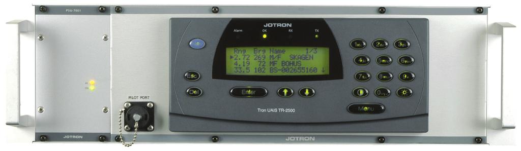
32 5 OPERATION The AIS BS includes a transponder to be used in a configuration with a Base Station Controller (BSC) Figure 5, TR-2600 AIS BS 5.1 Connecting power After connecting the antennas and Inputs/Outputs, the DC power can be connected to the TR-2600 transponder through the AC/DC Power supply unit, PSU-7002 in the rack. This PSU transform from V AC to 28 V DC. An optional DC input is provided in the PSU-7002, if automatic switchover to 24V DC is needed. The DC input voltage must be within 24VDC +30% / -10%. The power consumption is 60W. At startup, the TR-2600 will look for connected sensors and equipment for seconds. The display will show: Loading Please wait After a while the alarm status will be indicated. Press [Del] key to reset the alarm settings _Op&Ins MAN_TR2600_K 5-1
33 5.2 Description of keys Nav Menu Enter Esc Del : Not used : Show main menu : Accept current setting. Takes you one menu level forward. Enter sub-menu : Escape from current menu without saving. Takes you one menu level back. : Delete character at cursor : Scrolling menus : Adjust light intensity in display and keyboard buttons. Adjust contrast in display. 0-9 : Digits 0-9. Press keys with a short time interval to convert it to alphabetical character _Op&Ins MAN_TR2600_K 5-2
34 5.3 First configuration of TR-2600 transponder RS422 configuration If the RS422 ports on External display are used to communicate with a BSC, there is nothing necessary to configure before use. Just go further to chapter LAN configuration Press [Menu] key to enter Main menu. Main Menu 5/5 1 Current Sensors 2 Internal GPS 3 Messages 4 Diagnostic 5 Config Showing the number of sub-menus available below the selected menu Select 5 Config by [arrow down] key. Press [Enter] key. Menu: Config 1/3 1 I/O ports. 2 Buzzer 3 Change Password Select 1 I/O Ports followed by [Enter] key 82695_Op&Ins MAN_TR2600_K 5-3
35 Set Own IP address Menu: I/O Ports 2/3 1 Speed. 2 Own IP Address 3 BSC IP Address Select Own IP address then [Enter] key Now the IP address of the Tr-2600 can be entered: Menu: Own LAN Addr 1/2 1 IP = Port = 5000 Enter the IP address for the BS. See RFC 1597 for Address allocation in private internets The Port number is default to 5000, but can be altered to what the BSC needs. These must of course be the same on the TR-2600 and the BSC (Base Station Controller) Press [Enter] when done, you will also be asked for Password, and the correct password must be entered to continue, otherwise the same menu will appear. When you have saved the settings, you will press [ESC] to return to previous menu levels Set BSC IP address Applicable for UDP connection only Menu: I/O Ports 3/3 1 Speed. 2 Own IP Address 3 BSC IP Address 82695_Op&Ins MAN_TR2600_K 5-4
36 Select Own IP address then [Enter] key Now the IP address of the TR-2600 can be entered: Menu: BSC LAN Addr 1/2 1 IP = Port = As in Set Own IP address in the previous chapter, the settings must also be set here. Check what the IP address of your BSC is, and enters the same address here. It is NOT RECOMMENDED that you have a BSC connected to a LAN using DHCP, since IP addresses can then be altered from time to time. The PORT is default to 5100, but this can be changed, dependent of which port the BSC need. Restart the system to initiate new IP addresses. The AIS BS starts communicating through the PI (Presentation Interface) over Unicast UDP when the application is started after the base station controller (BSC) IP address is set. Default UDP ports used are 5000 (Base station listen port) and 5100 (BSC listen port) 82695_Op&Ins MAN_TR2600_K 5-5
37 5.4 TR-2600 Transponder Menus Menu Flowchart Rng Brg Name: 1/ NIKITA COLOR FESTIV PETER VESSEL Esc Menu Enter key 1 to 5 Main Menu 1/5 1 Current Sensors 2 Internal GPS 3 Messages 4 Diagnostic 5 Config Esc Enter NIKITA 1/15 MMSI: 444 Call: ETA: ----:0000 Dest: VIKSFJORD Type:0 Lat: N58d52.58 Lon: E010d45.51 ROT: 0 SOG: 10.0 KT COG: 3.2 Head: 45 Length: --- Beam:--- Draught: Nav.Stat: How to navigate in the menus/submenus If there is a number in front of the menu/submenu, you can select it directly by pressing the numeric key with the corresponding number. When no number is present in front of a submenu, use the arrow up/down keys to choose and press [Enter] key to select. Esc Esc Esc Esc Menu: Current Senso 1/5 LAT: N LON: E Pos Accur.: Low Pos Source: Internal HH:MM:SS DD/MM/YYYY Menu: Internal GPS 1/4 LAT: --- LON:--- Status: NoFix DD.MM.YY HH:MM:SS Menu: Message 1/2 1 Read Message 2 Send Message Menu: Diagnostic 1/6 1 BIIT 2 Alarm 3 System Indicators 4 History 5 SW Versions 6 Service Password 1 The [Esc] key takes you one step back. Passwords: Password 1: OP Password 2: SE Esc Menu: Config 1/3 1 I/O Ports 2 Buzzer 3 Change Password Password _Op&Ins MAN_TR2600_K 5-6
38 5.5 TR-2600 Transponder, Readout and Configuration Display received vessels Normal use operational display Range to ship in nautical miles Bearing of the received ship.. Name of the received ship. Rng Brg Name: 1/x NIKITA COLOR FESTIV PETER VESSEL Select the name of the ship by pressing [arrow down] key and [Enter] key. NIKITA 4/15 MMSI: 444 Call: ETA: ----:0000 Dest: VIKSFJORD Type:0 Lat: N58d52.58 Lon: E010d45.51 ROT: 0 SOG: 10.0 KT COG: 3.2 Head: 45 Length: --- Beam:--- Draught: Nav.Stat Select specific information by pressing [arrow down] key and [Enter] key. ETA: 30 /09 23:59 DD/MM HH:MM < > Press [Esc] key to go back one step _Op&Ins MAN_TR2600_K 5-7
39 5.5.2 Current Sensors / Dynamic Data menu Main Menu 1/5 1 Current Sensors 2 Internal GPS 3 Messages 4 Diagnostic 5 Config Select Current Sensor with numeric key [1] or press [Enter] key. Menu: Current Senso 1/5 LAT: --- LON:--- Pos. Accur.: Low Pos. Source: Internal HH:MM:SS DD/MM/YYYY This menu shows the data from the selected sensors onboard that the transponder is transmitting to the AIS system. Press [Esc] key twice to return to Main Menu Internal GPS Menu From the Main Menu select Internal GPS by pressing numeric key [2] or [arrow down] key and [Enter] key. Menu: Internal GPS 1/4 LAT: --- LON: --- Status: NoFix DD.MM.YY HH:MM:SS This menu shows the data from the internal GPS module. Press [Esc] key twice to return to Main Menu _Op&Ins MAN_TR2600_K 5-8
40 5.5.4 Messages Menu From the Main Menu select Message by pressing numeric key [3] or [arrow down] key and [Enter] key. Menu: Messages 1/2 1 Read Messages 2 Send Messages Select Read Messages by pressing [Enter] key or numeric key [1]. Menu: Received msg 0/0 The number of received messages will show in upper right corner. The transponder will show up to 100 messages. The latest received message will always be on top of the list. Select a message by [arrow up/down] key and [Enter] key to read the message. Press [Esc] key to return to Message Menu. From the Messages Menu select Send Messages by pressing numeric key [2] or [arrow down] key and [Enter] key. Enter Password < > When you try to Send Message, you must enter password 1 Type password 1 and press [Enter] key. Then you will be able to write a message as shown below Menu: ADDRESSED msg 1/5 Write Message Msg. Type: ADDRESSED MMSI Channel AUTO Send Message Select Write Message by pressing [Enter] key. Write message, select ADDRESSED, select MMSI and type in MMSI number to the receiving part. Select Send Message and [Enter] to send _Op&Ins MAN_TR2600_K 5-9
41 5.5.5 Diagnostic Menu From the Main Menu select Diagnostic by pressing numeric key [4] or [arrow down] key and [Enter] key. Menu: Diagnostic 1/6 1 BIIT 2 Alarm 3 System Indicators 4 History 5 SW Versions 6 Service This menu gives access to different submenus for readout of parameters. The only submenu who can give access to changes is the Service menu which is password protected. Select BITE menu by pressing [Enter] key or numeric key [1]. Menu: BIIT 1/7 Swr:... : Refl. Power.: Forw power.: Temperature...: Rssi AIS0...: Rssi AIS1.: Rssi DSC....: This menu gives BIIT readout values from the transponder. Press [Esc] key to go one step back. Select Alarm Status menu by pressing numeric key [2] or [arrow down] key and press [Enter ] key. Menu: Alarm Status 0/0 ** No data ** This menu shows the log over momentarily status alarms that have been visualized in the AIS display and signed for by pressing [Del] key, but are still valid. Press [Esc] key to go one step back. Select System Indicators menu by pressing numeric key [3] or [arrow down] key and press [Enter] key _Op&Ins MAN_TR2600_K 5-10
42 Menu: Indicators 1/1 UTC Clock ok This menu shows the momentarily status if sensor is connected. Press [Esc] key to go one step back. Select History menu by pressing numeric key [4] or [arrow down] key and press [Enter ] key. Menu: History 1/x Off 19 Jan :14 On 30 Dec :07 Off 14 May :44 This menu shows the log over when the transponder have been turned on or off. Press [Esc] key to go one step back. Select SW Version menu by pressing numeric key [5] or [arrow down] key and press [Enter ] key. Menu: SW-Version 1/6 AIS EC BS MMI BS LINK RF: S.No. xxxxx This menu shows the different software versions installed in the transponder. To get the Compilation date for each software version, select the software by [arrow up/down] keys and press [Enter] key. Compilation date ECBS Feb :21:19 This shows the Compilation date and time for this specific software. Press [Esc] key to go one step back. Repeat the procedure for the other software versions. Press [Esc] key twice to go back to Diagnostic menu _Op&Ins MAN_TR2600_K 5-11
43 Select Config menu by pressing numeric key [5] or [arrow down] key and press [Enter ] key. Menu: Config 1/3 1 I/O Ports 2 Buzzer 3 Change Password Config Menu When entering a submenu in the Config menu you have to enter password 2. When the password is accepted you have access to all parameters in the Config menu. If you escape from the Config menu you have to re-enter the password to change the parameters. Select I/O ports. menu by pressing numeric key [1] or [arrow up/down] keys and press [Enter ] key. Menu: I/O Ports 1/3 1 Speed 2 Own IP address 3 BSC IP address Press [Enter] key or numeric key [1] to select data speed. Menu: I/O Ports - Sp 1/6 P1 (Sensor1) 4800 P2 (Sensor2) 4800 P3 (Sensor3) 4800 P4 (ext.disp.) P5 (Pilot) P6 (Spare) This menu allows the setting of data speed at port1 to port 6 of 4800 b/s or b/s. Press [Enter] key to select P1. Enter Password When you try to change setting of an I/O port, you must enter password 1 P1 (Sensor1) 4800 =4800 = _Op&Ins MAN_TR2600_K 5-12
44 Select speed using [arrow up/down] keys and press [ Enter] key Repeat the prosedure for all ports. Press [Esc] key to return Confirm changes by [arrow up/down] keys and press [ Enter] key Selection of Own and BSC IP address is described in chapter 5.3 Save Changes? No = No = Yes Select Buzzer menu by pressing numeric key [2] or [arrow down] key and [Enter] key. Menu: Buzzer 1/3 1 Keyboard LOW 2 Info Beep On 3 Messages On Select Keyboard menu by pressing numeric key [1] or [Enter] key. Keyboard: LOW = OFF = HIGH Select keyboard status with [arrow up/down] keys and [Enter] key. Repeat procedure for Info Beep and Messages. Press [Esc] key twice to return to Config menu. Select Ch. Password menu by pressing numeric key [3] or [arrow down] key and [Enter] key. Change Password: < > Press [Enter] key Follow instructions Press [ Esc] key twice to return to operational display _Op&Ins MAN_TR2600_K 5-13
45 6 EQUIPMENT LIST 6.1 Standard supply No. Name Type Stock No. Qty. Remarks 1 19`` Rack Tray Schroff `` Rack Tray Mounting Kit Transponder unit TR PSU 7002 LEP240F Plug Kit Optional supply No. Name Type Stock No. Remarks 1 GPS antenna Procom GPS with mounting bracket with FLG bracket 2 Plug Kit for GPS antenna Transvoice type with mounting bracket with / bracket 4 Plug Kit for _Op&Ins MAN_TR2600_K 6-1

46 7 WIRING AND CONNECTIONS 7.1 TR-2600 AIS transponder, rear connections VHF Antenna Connector This is a BNC type antenna connector to be connected directly to an external VHF antenna or antenna splitter to receive and transmit VHF frequencies. For further information see section 10.5 and GPS Antenna Connector This is a TNC type antenna connector to be connected directly to an external GPS antenna or antenna splitter to receive GPS information. For further information see section VDC Connector This is a connector to connect 24VDV power to the transponder. Normally connected to the PSU-7002 Power supply For further information see section Ground Tag (GND) This Ground Tag is to be connected directly to the ships metal Extra I/O Connector Factory use only _Op&Ins MAN_TR2600_K 7-1

47 7.1.6 Programming Connector Factory use only Junction Box Connector This is a 37 pin D-sub female connector for connections between the transponder and sensor, RS422<->RS232 converter and RS422 <->LAN converter (TCP/IP). It is also a LAN port with UDP protocol on this connector LAN Connector This 9 pin D-sub connector is described in chapter 7.4. Is normally connected to the 5-Port LAN switch 7.2 Description of connectors Description of 24VDC connection to transponder 24VDC Connector for cable, front side GND + 24VDC 0VDC 82695_Op&Ins MAN_TR2600_K 7-2
48 7.3 Junction Box Connector, 37 pin D-sub Pin Nr. Name Function In/Out 1 AIS TD1-B Reserved 2 AIS TD1-A Reserved 3 AIS 1 in (B) AIS RD1-B (External GPS) In 4 AIS 1 in (A) AIS RD1-A ( ) In 5 AIS TD2-B Reserved 6 AIS TD2-A Reserved 7 AIS 2 in (B) AIS RD2-B In 8 AIS 2 in (A) AIS RD2-A In 9 AIS TD3-B Reserved 10 AIS TD3-A Reserved 11 AIS 3 in (B) AIS RD3-B In 12 AIS 3 in (A) AIS RD3-A In 13 AIS 4 out (B) AIS TD4-B (External Display) Out 14 AIS 4 out (A) AIS TD4-A (External Display) Out 15 AIS 4 in (B) AIS RD4-B In 16 AIS 4 in (A) AIS RD4-A In 17 AIS 5 out (B) AIS TD5-B 18 AIS 5 out (A) AIS TD5-A 19 AIS 5 in (B) AIS RD5-B In 20 AIS 5 in (A) AIS RD5-A In 21 AIS 6 out (B) AIS TD6-B Out 22 AIS 6 out (A) AIS TD6-A Out 23 AIS 6 in (B) AIS RD6-B In 24 AIS 6 in (A) AIS RD6-A In 25 AIS 7 out (B) AIS TD7-B Reserved 26 AIS 7 out (A) AIS TD7-A Reserved 27 AIS 7 in (B) AIS RD7-B (DGNSS data) In 28 AIS 7 in (A) AIS RD7-A (DGNSS data) In 29 RS-232 TX Out 30 RS-232 RX In 31 ALARM Out NC to #33 32 ALARM Out NO to #33 33 ALARM CO switch between #31 and #32 34 I/O Spare 35 Future warning for Backup Power - 36 GND Ground - Cable screen Chassis GND Signal state definitions Port 1 to 7 are RS422 with A and B lines. The idle, marking, logical 1, OFF or stop bit states are defined by a negative voltage on line A with respect to line B. The active, spacing, logical 0, ON or start bit states are defined by a positive voltage on line A with respect to line B. It should be noted that the above A with respect to B levels are inverted from the voltage input/output requirements of standard UARTs and that many line drivers and receivers provide a logic inversion _Op&Ins MAN_TR2600_K 7-3
49 7.4 Description of LAN connector (UDP) Contains Ethernet 10Mbit Twisted pair interface and RS232 serial port with Tx and Rx. Service connector, 9 pins Dsub: Nr. Name Function In/Out 1 Ether_Tx+ Ethernet Transceive Data+ Out 2 Ether_Tx- Ethernet Transceive Data- Out 3 Ether_Rx+ Ethernet Receive Data+ In 4 Ether_Rx- Ethernet Receive Data- In 5 GND Ground - 6 PC_UART_Tx PC serial port Transmit Data RS232 In 7 PC_UART_Rx PC serial port Receive Rata RS232 Out 8 +14V +14 V, max 300mA. - 9 NC Not Connected Redundancy wiring 82695_Op&Ins MAN_TR2600_K 7-4
50 7.6 Connection to PC serial port using RS422 to RS232 converter On the RS232 side of the converter, a standard RS2323 extender cable must be used. RS422 to RS232 converter. ADAM 4520 Names TX- RD-A (-) Junction Box 23 TR pin D-sub 16 TX+ RD-B (+) RX- TD-A (-) RX+ TD-B (+) (R)+Vs (B)GND - + 9V Battery 82695_Op&Ins MAN_TR2600_K 7-5
51 8 ALARM MESSAGES See tables of alarms and notifications in Technical Manual paragraph Receiver malfunction If the error messages Rx1 or Rx2 appears on the LCD Display, this indicate that the test of the TDMA receivers 1 or 2 has failed Receiver tests Every time a transmission is done and the receiver is on the same channel as the transmitter, the receiver measures the signal level (RSSI) and will give an alarm if too low signal level is obtained. This means that this test will include the complete receiver chain. The alarm messages are as follows: Alarm ID in ALR sentence on Display indication IEC /2 ports TDMA receiver 1 error Rx1 ID 003 TDMA receiver 2 error Rx2 ID Position Sensor fallback conditions Position sensor priority: 1 External DGNSS 2 Internal DGNSS 3 External EPFS, uncorrected 4 Internal GNSS, uncorrected 5 no sensor position 82695_Op&Ins MAN_TR2600_K 8-1
52 9 LIST OF VHF CHANNELS Channel no. Frequency Channel no. Channel 2087 = Channel 87B Frequency Channel no. Channel 2088 = Channel 88B Frequency Channel no. Frequency _Op&Ins MAN_TR2600_K 9-1
53 10 OUTLINE DRAWINGS 10.1 TR-2600 AIS BASE STATION 82695_Op&Ins MAN_TR2600_K 10-1
54 10.2 TR-2600 AIS Transponder 82695_Op&Ins MAN_TR2600_K 10-2

55 10.3 Procom CXL 2-1/l Maritime VHF Antenna with FLG Bracket 82695_Op&Ins MAN_TR2600_K 10-3

56 10.4 Procom GPS 4 Antenna 82695_Op&Ins MAN_TR2600_K 10-4

57 10.5 BNC connector 95299, Suhner 24BNC /133NE 10.6 FME Connector Female 80588, Holund _Op&Ins MAN_TR2600_K 10-5
58 10.7 BNC Connector Male 80577, Suhner 11BNC-50-2 / 133NE 10.8 TNC Connector Male Suhner 11TNC-3-6 / 133NE 82695_Op&Ins MAN_TR2600_K 10-6
59 10.9 N Connector Male 80581, Suhner 11N / 133NE VDC Power Connector 81509, AMP C091AT _Op&Ins MAN_TR2600_K 10-7
60 11 REGISTRATION FORM Cut here and return this page to JOTRON TR-2600 Installation form Station name Country Owner / Company Data MMSI Number Comments: Contact Name #1 Contact Name #2 Telephone Number(s) Telephone Number(s) Office: GSM: Office: GSM: TR-2600 AIS Transponder serial number: Installation completed and successfully commissioned by: Technician, (type name) Service provider / company Place Date Signature Please fill in with capital letters This form must be returned to Jotron AS, Fax.: (attention service department) in order to have a valid 24 months product warranty _Op&Ins MAN_TR2600_K 11-1

61 82695_Op&Ins MAN_TR2600_K 11-2
FURUNO DEEPSEA WORLD Class-A Universal AIS Automatic Identification System. The future today with FURUNO's electronics technology.
 R FURUNO DEEPSEA WORLD Class-A Universal AIS Automatic Identification System Model FA-100 The AIS improves the safety of navigation by assisting in the efficient navigation of ships, protection of the
i-ais-bs1 AIS Shore Station Installation and User Manual Rev 0.1
 i-ais-bs1 AIS Shore Station Installation and User Manual Rev 0.1 2013 IMPORTANT NOTICES The operator of this equipment must read and follow the descriptions in this manual. Wrong operation or maintenance
R40 Mk III AIS Base Station
 R40 Mk III AIS Base Station The new R40 Mk III AIS Base Station from Saab TransponderTech is a result of our on-going efforts to enhance all our products. The R40 Mk III is equipped with a new Base Station
Use the standard Mounting Kit. For dimensions and positioning of holes see Figure 14-1 TR-8000 Transponder Unit- mechanical dimensions
 8 Installation 8.1 Mechanical Mounting 8.1.1 Transponder unit Use the standard Mounting Kit. For dimensions and positioning of holes see Figure 14-1 TR-8000 Transponder Unit- mechanical dimensions When
IMO/IALA Seminar on AIS Session No: 3 Paper No: 2
 IMO/IALA Seminar on AIS Session No: 3 Paper No: 2 1. Abstract The onboard installation of Automatic Identification System (AIS) With the implementation of AIS a substantial enhancement of maritime safety
Addendum 1.4_2. (Addendum to MX420 Operator s Manual)
") _2 (Addendum to MX420 ) September, 2007 Table of Contents About this document..1 MX575 Heading & Rate of Turn 2 MX575 as a D/GPS Compass only 2 MX575 as a D/GPS Compass with Navigation Functionality.....4
_2 (Addendum to MX420 ) September, 2007 Table of Contents About this document..1 MX575 Heading & Rate of Turn 2 MX575 as a D/GPS Compass only 2 MX575 as a D/GPS Compass with Navigation Functionality.....4
Installation and Quick Reference Guide. Disclaimer and warranty 2. Contents of this box 2. Brief background to AIS 3.
 AI3000 AIS Receiver ai3000vf rev 6b Installation and Quick Reference Guide Contents Page Number Disclaimer and warranty 2 Contents of this box 2 Brief background to AIS 3 Introduction 3 Installing the
KS-200A/B. ˵à Êé. AIS Class B Transponder KS-200A AIS Receiver KS-200B
 R KS-200A/B KS-200A/B ˵à Êé OPERATOR`S MANUAL AIS Class B Transponder KS-200A AIS Receiver KS-200B SAFETY INSTRUCTIONS Safety Instructions for the Operator WARNING Do not open the equipment. Only qualified
R5 SUPREME AIS Transponder System
 Saab TransponderTech R5 SUPREME AIS Transponder System OPERATION & INSTALLATION MANUAL This page is intentionally empty i Copyright The entire contents of this manual and its appendices, including any
USERS MANUAL TR-710.
 USERS MANUAL TR-710 www.jotron.com EC Declarations of Conformity, available at www.jotron.com Read this Users Manual fully to familiarise yourself with the equipments functions and facilities. Abbreviations
SPECIAL SPECIFICATION 6744 Spread Spectrum Radio
 2004 Specifications CSJ 0924-06-244 SPECIAL SPECIFICATION 6744 Spread Spectrum Radio 1. Description. Furnish and install spread spectrum radio system. 2. Materials. Supply complete manufacturer specifications
ANNEX 12. RESOLUTION MSC.74(69) (adopted on 12 May 1998) ADOPTION OF NEW AND AMENDED PERFORMANCE STANDARDS
 (adopted on 12 May 1998) ADOPTION OF NEW AND AMENDED PERFORMANCE STANDARDS") RESOLUTION MSC.74(69) (adopted on 12 May 1998) ADOPTION OF NEW AND AMENDED PERFORMANCE STANDARDS THE MARITIME SAFETY COMMITTEE, RECALLING Article 28(b) of the Convention on the International Maritime Organization
RESOLUTION MSC.74(69) (adopted on 12 May 1998) ADOPTION OF NEW AND AMENDED PERFORMANCE STANDARDS THE MARITIME SAFETY COMMITTEE, RECALLING Article 28(b) of the Convention on the International Maritime Organization
RESOLUTION MSC.112(73) (adopted on 1 December 2000) ADOPTION OF THE REVISED PERFORMANCE STANDARDS FOR SHIPBORNE GLOBAL POSITIONING SYSTEM (GPS)
 (adopted on 1 December 2000) ADOPTION OF THE REVISED PERFORMANCE STANDARDS FOR SHIPBORNE GLOBAL POSITIONING SYSTEM (GPS)") MSC 73/21/Add.3 RESOLUTION MSC.112(73) FOR SHIPBORNE GLOBAL POSITIONING SYSTEM THE MARITIME SAFETY COMMITTEE, RECALLING Article (28(b) of the Convention on the International Maritime Organization concerning
MSC 73/21/Add.3 RESOLUTION MSC.112(73) FOR SHIPBORNE GLOBAL POSITIONING SYSTEM THE MARITIME SAFETY COMMITTEE, RECALLING Article (28(b) of the Convention on the International Maritime Organization concerning
OPERATION & INSTALLATION MANUAL
 Saab TransponderTech R5 SOLID AIS System OPERATION & INSTALLATION MANUAL This page is intentionally empty i Copyright The entire contents of this manual and its appendices, including any future updates
Saab TransponderTech. INSTALLATION MANUAL R4 AIS Class A Transponder System
 Saab TransponderTech INSTALLATION MANUAL R4 AIS Class A Transponder System i Copyright The entire contents of this manual and its appendices, including any future updates and modifications, shall remain
The FA-50 offers accurate information for collision avoidance
 The FA-50 offers accurate information for collision avoidance with GPS antenna GPA-017S FURUNO s FA-50 class-b AIS transponder receives navigation data from AIS-equipped vessels nearby that can be utilized
ONCORE ENGINEERING NOTE M12 Oncore
 ONCORE ENGINEERING NOTE M12 Oncore 1. Product Specifications 2. Basic Description 3. Mechanical 4. Environmental 5. Electrical 6. RF Characteristics of Receiver 7. RF Requirements for Antenna 8. Performance
Saab TransponderTech
 Saab TransponderTech R4 Combined AIS & Navigation System This page is intentionally empty Copyright The content of this document and its attachments shall remain our property. They may not without our
LD2342 USWM V1.6. LD2342 V1.4 Page 1 of 18
 LD2342 USWM V1.6 LD2342 V1.4 Page 1 of 18 GENERAL WARNINGS All Class A and Class B marine Automatic Identification System (AIS) units utilize a satellite based system such as the Global Positioning Satellite
NMEA2000- Par PGN. Mandatory Request, Command, or Acknowledge Group Function Receive/Transmit PGN's
 PGN Number Category Notes - Datum Local geodetic datum and datum offsets from a reference datum. T The Request / Command / Acknowledge Group type of 126208 - NMEA - Request function is defined by first
R4 AIS Class A Transponder System
 Saab TransponderTech R4 AIS Class A Transponder System Operator Manual This page is intentionally empty i Copyright The entire contents of this manual and its appendices, including any future updates and
RECOMMENDATION ITU-R M.825-3*, **
 Rec. ITU-R M.825-3 1 RECOMMENDATION ITU-R M.825-3*, ** CHARACTERISTICS OF A TRANSPONDER SYSTEM USING DIGITAL SELECTIVE CALLING TECHNIQUES FOR USE WITH VESSEL TRAFFIC SERVICES AND SHIP-TO-SHIP IDENTIFICATION
GPS10RBN-26: 10 MHz, GPS Disciplined, Ultra Low Noise Rubidium Frequency Standard
 GPS10RBN-26: 10 MHz, GPS Disciplined, Ultra Low Noise Rubidium Standard Key Features Completely self-contained unit. No extra P.C needed. Full information available via LCD. Rubidium Oscillator locked
MN5020HS Smart GPS Antenna Module
 1 Description The Micro Modular Technologies MN5020HS Smart Global Positioning System (GPS) Antenna Module is a complete 20-channel receiver with an integrated 18 x 18 mm patch antenna. With this highly
Specifications subject to change without notice Heartbeat of the Smart Grid
 Model 1151B Network Clock Preliminary, April 2013 Specifications subject to change without notice Heartbeat of the Smart Grid TM Clock defines a new generation of advanced timing devices, becoming the
KanAtoN 1 / 3 AIS Transponder. Installation Manual
 Orolia S.A.S. Z.I. des Cinq Chemins 56520 GUIDEL - FRANCE Telephone: +33 (0)2 97 02 49 49 Fax: +33 (0)2 97 65 00 20 Web : http://www.mcmurdomarinesystems.com An Orolia Group Business DATE : 20/072012 KanAtoN
INTERNATIONAL STANDARD
 INTERNATIONAL STANDARD IEC 61993-2 First edition 2001-12 Maritime navigation and radiocommunication equipment and systems Automatic identification systems (AIS) Part 2: Class A shipborne equipment of the
Fisheries and Marine Resources (Automatic Identification System) Regulations
 Regulations") Fisheries and Marine Resources (Automatic Identification System) Regulations 2016 GN No. 116 of 2016 Government Gazette of Mauritius No. 47of 28 May 2016 THE FISHERIES AND MARINE RESOURCES ACT Regulations
Fisheries and Marine Resources (Automatic Identification System) Regulations 2016 GN No. 116 of 2016 Government Gazette of Mauritius No. 47of 28 May 2016 THE FISHERIES AND MARINE RESOURCES ACT Regulations
SA-320 Installation Guide SA-320. Installation Guide. Date: Mar, 2011 Version: 2.5. All Rights Reserved
 SA-320 Installation Guide Date: Mar, 2011 Version: 2.5 All Rights Reserved Page 1 TABLE OF CONTENTS 1. Product Overview......3 1.1 Main Features...3 1.2 Applications.....3 1.3 Package Content.....3 2.
NVR-1000 VHF RADIOTELEPHONE
 NVR-1000 VHF RADIOTELEPHONE USER S MANUAL NEW SUNRISE NOTICE TO USERS - Thanks for your purchasing this product VHF radio telephone. - The copyright of this manual is owned by the manufacturer, NEW SUNRISE
RESOLUTION MSC.233(82) (adopted on 5 December 2006) ADOPTION OF THE PERFORMANCE STANDARDS FOR SHIPBORNE GALILEO RECEIVER EQUIPMENT
 (adopted on 5 December 2006) ADOPTION OF THE PERFORMANCE STANDARDS FOR SHIPBORNE GALILEO RECEIVER EQUIPMENT") MSC 82/24/Add.2 RESOLUTION MSC.233(82) THE MARITIME SAFETY COMMITTEE, RECALLING Article 28(b) of the Convention on the International Maritime Organization concerning the functions of the Committee, RECALLING
MSC 82/24/Add.2 RESOLUTION MSC.233(82) THE MARITIME SAFETY COMMITTEE, RECALLING Article 28(b) of the Convention on the International Maritime Organization concerning the functions of the Committee, RECALLING
NMEA 2000 Parameter Group Numbers and Description as of August 2007 NMEA 2000 DB Ver
 Category General & or Mandatory ISO Acknowledgment This message is provided by ISO 11783 for a handshake mechanism between transmitting and receiving devices. This message is the possible response to acknowledge
i-ais-an1 AIS AtoN (Aids-to-Navigation) Station Installation and User Manual Rev. 2.1
 Station Installation and User Manual Rev. 2.1") i-ais-an1 AIS AtoN (Aids-to-Navigation) Station Installation and User Manual Rev. 2.1 2011 IMPORTANT NOTICES The operator of this equipment must read and follow the descriptions in this manual. Wrong operation
i-ais-an1 AIS AtoN (Aids-to-Navigation) Station Installation and User Manual Rev. 2.1 2011 IMPORTANT NOTICES The operator of this equipment must read and follow the descriptions in this manual. Wrong operation
User Configurable POSITION 303 DATA OUTPUT 450 HEADING 910
 WinFrog Device Group: Device Name/Model: Device Manufacturer: Device Data String(s) Output to WinFrog: WinFrog Data String(s) Output to Device: WinFrog Data Item(s) and their RAW record: GPS TRACS TDMA
GPS Time and Frequency Reference Receiver
 $ GPS Time and Frequency Reference Receiver Symmetricom s 58540A GPS time and frequency reference receiver features: Eight-channel, parallel tracking GPS engine C/A Code, L1 Carrier GPS T-RAIM satellite
AW2400iTR USER S MANUAL 2.4 GHz Indoor Wireless Ethernet Radio
 USER S MANUAL 2.4 GHz Indoor Wireless Ethernet Radio Industrial-grade, long-range wireless Ethernet systems AvaLAN W I R E L E S S Thank you for your purchase of the AW2400iTR Indoor Wireless Ethernet
Brookhouse imux Mk3 Installation and operating instructions
 Introduction Brookhouse imux Mk3 Installation and operating instructions Standard model and model ST (Seatalk) The Brookhouse imux is based on Brookhouse NMEA 0183 multiplexer model AIS, with Wifi capability
AIS Training. AIS Technology in Digital Yacht Products Explained. Digital Yacht Ltd TEL
 AIS Training AIS Technology in Digital Yacht Products Explained Digital Yacht Ltd www.digitalyacht.co.uk TEL + 44 1179 554474 What is AIS? The Automatic Identification System (AIS) is the biggest advance
INTERNATIONAL STANDARD
 INTERNATIONAL STANDARD IEC 62320-2 Edition 2.0 2016-10 colour inside Maritime navigation and radiocommunication equipment and systems Automatic identification system (AIS) Part 2: AIS AtoN Stations Operational
[ tima-datasheet-en v11.1 ]
![[ tima-datasheet-en v11.1 ]](/thumbs/92/109134204.jpg "[ tima-datasheet-en v11.1 ]") specifically designed for protection, automation and control applications in power systems 60 ns (99%) maximum time deviation single or dual 10/100Base-T Ethernet port(s) VLAN / IEEE 802.1Q support RS232
specifically designed for protection, automation and control applications in power systems 60 ns (99%) maximum time deviation single or dual 10/100Base-T Ethernet port(s) VLAN / IEEE 802.1Q support RS232
SRT Marine Technology. LD2342 V1.4 Page 1 of 22
 LD2342 V1.4 Page 1 of 22 LD2342 V1.4 Page 2 of 22 2 LD2342 V1.4 Page 3 of 22 GENERAL WARNINGS All marine Automatic Identification System (AIS) units utilise a satellite based system such as the Global
RECOMMENDATION ITU-R M *
 Rec. ITU-R M.823-3 1 RECOMMENDATION ITU-R M.823-3 * Technical characteristics of differential transmissions for global navigation satellite systems from maritime radio beacons in the frequency band 283.5-315
INSTALLATION AND OPERATING MANUAL
 INSTALLATION AND OPERATING MANUAL FOR RBDA-PCS-1/25W-90-A INDOOR REPEATER TABLE OF CONTENTS PARAGRAPH PAGE NO BDA OVERVIEW 3 BDA BLOCK DIAGRAM DESCRIPTION 3 FCC INFORMATION FOR USER 3 BDA BLOCK DIAGRAM
Brief installation guide for FA-100 Universal AIS
 Attention: All Furuno Distributors Date: April 2, 2003 SB No: FSB02-0002 Number of Pages: 5 Brief installation guide for FA-100 Universal AIS The purpose of this document is to provide and highlight important
FURUNO DEEPSEA WORLD Class-A Universal AIS Automatic Identification System. The future today with FURUNO's electronics technology.
 R FURUNO DEEPSEA WORLD Class-A Universal AIS Automatic Identification System Model FA-100 The AIS improves the safety of navigation by assisting in the efficient navigation of ships, protection of the
MPR kHz Reader
 MPR-5005 Page 1 Doc# 041326 MPR-5005 125kHz Reader Installation & Operation Manual - 041326 MPR-5005 Page 2 Doc# 041326 COPYRIGHT ACKNOWLEDGEMENTS The contents of this document are the property of Applied
The FA-30 delivers Real-Time AIS information to navigation systems providing critical collision avoidance information
 The FA-30 delivers Real-Time AIS information to navigation systems providing critical collision avoidance information Acquisition and tracking of traffic around your vessel is absolutely necessary for
GPS10R - 10 MHz, GPS Disciplined, Rubidium Frequency Standards
 GPS10R - 10 MHz, GPS Disciplined, Rubidium Standards Key Features Completely self-contained units. No extra P.C Multiple 10 MHz Outputs plus other outputs needed. Full information available via LCD. RS232
SA-320 Installation Guide SA-320. Installation Guide. Date: June, 2007 Version: 2.2. All Rights Reserved
 SA-320 Installation Guide Date: June, 2007 Version: 2.2 All Rights Reserved Page 1 TABLE OF CONTENTS 1. Product Overview......3 1.1 Main Features...3 1.2 Applications.....3 1.3 Package Content.....3 2.
SOUTHERN AVIONICS COMPANY. SE125 Transmitter. SE125 Transmitter 1-1
 1-1 1 Introduction The SE Series transmitters are computer controlled systems designed around an embedded microprocessor. These systems are capable of remote monitoring and maintenance via Ethernet (optional).
Smart Design Technology Co., Ltd.
 Mars700Mini-TMC GNS TC5000 TMC Module Smart Design Technology Co., Ltd. 20F-8, No.107, Sec 1,Jhongshan Rd. Sinjhuang City, Taipei County 242, Taiwan Phone: +886-2-8522-7628 Fax: +886-2-8522-7784 Contact:
TECHNICAL COMMITTEE 80: MARITIME NAVIGATION AND RADIOCOMMUNICATION EQUIPMENT AND SYSTEMS INTERNATIONAL ELECTROTECHNICAL COMMISSION
 TECHNICAL COMMITTEE 80: MARITIME NAVIGATION AND RADIOCOMMUNICATION EQUIPMENT AND SYSTEMS INTERNATIONAL ELECTROTECHNICAL COMMISSION IEC TECHNICAL COMMITTEE 80: MARITIME NAVIGATION AND RADIOCOMMUNICATION
Scalable Ionospheric Analyser SIA 24/6
 Scalable Ionospheric Analyser SIA 24/6 Technical Overview Functional description The ATRAD Scalable Ionospheric Analyser SIA24/6 is designed to observe ionospheric irregularities and their drift in the
Installation & Quick Start Guide CLB2000 Class B AIS Transponder
 Installation & Quick Start Guide CLB2000 Class B AIS Transponder QUICK START CLB2000 - VR1.01 1. Introduction Congratulations on the purchase of your CLB2000 Class B AIS Transponder. It is recommended
COPYRIGHT DISCLAIMER. Contact us at:
 COPYRIGHT The entire contents of this instruction manual, including any future updates, revisions, and modifications, shall remain the property of AMEC at all times. Unauthorized copies or reproduction
EXECUTE Shiloh Road Alpharetta, Georgia (770) FAX (770) Toll Free
 FAX (770) Toll Free") Instruction Manual Model 1586-06 RF Attenuator May 2009 Rev A 1 2 3 12.5 53.5 16.3 MODEL 1586 RF ATTENUATOR CROSS TECHNOLOGIES INC. EXECUTE PS1 PS2 Data, drawings, and other material contained herein are
Instruction Manual Model 1586-06 RF Attenuator May 2009 Rev A 1 2 3 12.5 53.5 16.3 MODEL 1586 RF ATTENUATOR CROSS TECHNOLOGIES INC. EXECUTE PS1 PS2 Data, drawings, and other material contained herein are
RESOLUTION MSC.401(95) (Adopted on 8 June 2015) PERFORMANCE STANDARDS FOR MULTI-SYSTEM SHIPBORNE RADIONAVIGATION RECEIVERS
 (Adopted on 8 June 2015) PERFORMANCE STANDARDS FOR MULTI-SYSTEM SHIPBORNE RADIONAVIGATION RECEIVERS") ANNEX 17 MSC 95/22/Add.2 Annex 17, page 1 THE MARITIME SAFETY COMMITTEE, RECALLING Article 28(b) of the Convention on the International Maritime Organization concerning the functions of the Committee,
ANNEX 17 MSC 95/22/Add.2 Annex 17, page 1 THE MARITIME SAFETY COMMITTEE, RECALLING Article 28(b) of the Convention on the International Maritime Organization concerning the functions of the Committee,
GPS-41EBR GPS-41EBF. GPS Receiver Module GPS-41EB. Fast Acquisition Enhanced Sensitivity 12 Channel GPS Sensor Module FEATURES. Ordering Information
 FEATURES 12 parallel channel GPS receiver 4000 simultaneous time-frequency search bins SBAS (WAAS, EGNOS) support High Sensitivity: -140dBm acquisition sensitivity -150dBm tracking sensitivity Fast Acquisition:
Localizer provides signal generation over the Localizer band of to MHz with 90 Hz and 150 Hz tones, amplitude modulated
 The IFR 4000 verifies the operation and installation of ILS, VOR and Marker Beacon receivers and VHF/UHF AM/FM and HF AM/SSB transceivers. The IFR 4000, with its lightweight size (under 8 lbs.), long run
----STAR S86 GPS Receiver. User Guide. SOUTH CO., Ltd.
 ----STAR S86 GPS Receiver User Guide SOUTH CO., Ltd. www.southsurveying.com Sales@SOUTHsurveying.com 2 CONTENTS Chapter 1 Introduction... 1 STAR S86 GPS - System Summary... 1 Technical Specification...
AW900xTR USER S MANUAL 900 MHz Outdoor Wireless Ethernet Radio
 USER S MANUAL 900 MHz Outdoor Wireless Ethernet Radio Industrial-grade, long-range wireless Ethernet systems Thank you for your purchase of the AW900xTR Outdoor Wireless Ethernet Radio. The AW900xTR includes:
PRX4SERL Four Zone Receiver Decoder
 PRX4SERL Four Zone Receiver Decoder Operating Manual Microframe Corporation 604 S. 12 th Street Broken Arrow, OK 74012 Tel: (918) 258-4839 Toll Free: 1-800-635-3811 Website: www.microframecorp.com E-mail:
INTERNATIONAL STANDARD
 INTERNATIONAL STANDARD IEC 62287-1 First edition 2006-03 Maritime navigation and radiocommunication equipment and systems Class B shipborne equipment of the automatic identification system (AIS) Part 1:
Ian D Souza (1), David Martin (2)
, David Martin (2)") NANO-SATTELITE DEMONSTRATION MISSION: THE DETECTION OF MARITIME AIS SIGNALS FROM LOW EARTH ORBIT SMALL SATELLITE SYSTEMS AND SERVICES SYMPOSIUM Pestana Conference Centre Funchal, Madeira - Portugal 31
NANO-SATTELITE DEMONSTRATION MISSION: THE DETECTION OF MARITIME AIS SIGNALS FROM LOW EARTH ORBIT SMALL SATELLITE SYSTEMS AND SERVICES SYMPOSIUM Pestana Conference Centre Funchal, Madeira - Portugal 31
This is by far the most ideal method, but poses some logistical problems:
 NXU to Help Migrate to New Radio System Purpose This Application Note will describe a method at which NXU Network extension Units can aid in the migration from a legacy radio system to a new, or different
MC108A-2 RF MULTI-COUPLER USER S GUIDE
 MC108A-2 RF MULTI-COUPLER USER S GUIDE Systems Engineering & Management Company 1430 Vantage Court Vista, California 92081 PROPRIETARY INFORMATION THE INFORMATION CONTAINED IN THIS DOCUMENT CONSTITUTES
Hub and Cluster. ogramming Manual. Pro MAN3090
 Hub and Cluster Pro ogramming Manual MAN3090 Contents Introduction 3 Radio Channels 28 System Overview 3 Currently Used 30 RCC RCC Ch 30 System Design 4 Device RCC Ch 30 Manual Select 30 Compatibility
Sperry Marine Northrop Grumman
 Sperry Marine 2005 Northrop Grumman Table of Contents CHAPTER 1: CHAPTER 2: CHAPTER 3: CHAPTER 4: CHAPTER 5: CHAPTER 6: WHERE ARE YOU GOING? TRANSMITTING HEADING DEVICES DETERMINING HEADING BY SATELLITE
RECOMMENDATION ITU-R M
 参考資料 - 作 -2-1 Rec. ITU-R M.1842-1 1 RECOMMENDATION ITU-R M.1842-1 Characteristics of VHF radio systems and equipment for the exchange of data and electronic mail in the maritime mobile service RR Appendix
Base Station Commissioning
 CHAPTER 7 Base Station Commissioning In This Chapter: Commissioning Overview, page 78 Alarms, page 80 Receiver Sensitivity Test, page 81 Transmit Power Tests, page 87 Network Connection and Ping Test,
T108, GPS/GLONASS/BEIDOU Time Server
 T108, GPS/GLONASS/BEIDOU Time Server Galileo (Europe) and QZSS (Japan) ready NTP Time server / Multi-GNSS Primary Clock, with PoE and advanced I/O synchronization features. - Static applications - HEOL-T108:
RECOMMENDATION ITU-R BT *
 Rec. ITU-R BT.656-4 1 RECOMMENDATION ITU-R BT.656-4 * Interfaces for digital component video signals in 525-line and 625-line television systems operating at the 4:2:2 level of Recommendation ITU-R BT.601
GPS RECEIVER GP-320B
 GPS RECEIVER GP-320B SAFETY INSTRUCTIONS CAUTION Confirm that the power supply voltage is compatible with the voltage rating of the equipment. Connection to the wrong power supply can cause fire or damage
RIGOL Data Sheet. DG3000 Series Function/Arbitrary Waveform Generator DG3121A, DG3101A, DG3061A. Product Overview. Easy to Use Design.
 RIGOL Data Sheet DG3000 Series Function/Arbitrary Waveform Generator DG3121A, DG3101A, DG3061A Product Overview DG3000 Series Function/Arbitrary Waveform Generators adopt DDS technology, which enables
TCG 02-G FULL FEATURED SATELLITE CLOCK KEY FEATURES SUPPORTS
 FULL FEATURED SATELLITE CLOCK TCG 02-G The TCG 02-G is a highly accurate, full featured GPS and GLONASS (GNSS) clock. Offering multiple oscillator options, Time Code and Frequency outputs, it fits virtually
AT-XTR-7020A-4. Multi-Channel Micro Embedded Transceiver Module. Features. Typical Applications
 AT-XTR-7020A-4 Multi-Channel Micro Embedded Transceiver Module The AT-XTR-7020A-4 radio data transceiver represents a simple and economical solution to wireless data communications. The employment of an
MARITIME AND ENERGY PRODUCT CATALOGUE NOVEMBER
 MARITIME AND ENERGY PRODUCT CATALOGUE NOVEMBER 2018 www.jotron.com Introduction Jotron offers an extensive and flexible range of safety products within GMDSS, AIS and lights. The Jotron GMDSS product
QK-A026/024 Wireless AIS+GPS Receiver
 Features QK-A026/024 Wireless AIS+GPS Receiver Two independent receivers monitoring AIS channels (161.975MHz &162.025MHz) and decoding both channels simultaneously. Sensitivity up to -106 dbm@30% PER Up
Product Documentation
 Prepared by Subject Resp. Approved by Ketil Vanebo Geir Godheim Geir Godheim NERA F77 Specifications subject to changes without notice LIST OF CONTENT: 1. GENERAL... 2 2. LIST OF MATERIEL... 2 3. STANDARD
GPS Receiver. UT-41R (DB9 and PS2 cable) Fast Acquisition Enhanced Sensitivity 12 Channel GPS Sensor Receiver. Features
 Fast Acquisition Enhanced Sensitivity 12 Channel GPS Sensor Receiver. Features") GPS Receiver Features 12 parallel channel GPS receiver 4100 simultaneous time-frequency search bins SBAS (WAAS, EGNOS) support -140dBm acquisition sensitivity -150dBm tracking sensitivity < 10 second hot
GPS Receiver Features 12 parallel channel GPS receiver 4100 simultaneous time-frequency search bins SBAS (WAAS, EGNOS) support -140dBm acquisition sensitivity -150dBm tracking sensitivity < 10 second hot
Thank you for buying this AIS antenna splitter.
 Thank you for buying this AIS antenna splitter. This product has been engineered to offer you the highest level of performance and durability and we hope that it will provide many years of reliable service.
UniTraQ OEM Module. GT-310F (Flash version) Fast Acquisition Enhanced Sensitivity 12 Channel GPS Sensor Module. Features
 Fast Acquisition Enhanced Sensitivity 12 Channel GPS Sensor Module. Features") UniTraQ OEM Module Features 12 parallel channel GPS receiver 4000 simultaneous time-frequency search bins SBAS (WAAS, EGNOS) support Programmable Flash version -140dBm acquisition sensitivity -150dBm tracking
UniTraQ OEM Module Features 12 parallel channel GPS receiver 4000 simultaneous time-frequency search bins SBAS (WAAS, EGNOS) support Programmable Flash version -140dBm acquisition sensitivity -150dBm tracking
di-gps Eco ProSumer PS10-M digital images GPS receiver
 di-gps Eco ProSumer PS10-M digital images GPS receiver Users Guide Ver 1.03 Please visit our website www.di-gps.com for the latest version of the user guide CONTENTS CONTENTS... 1 INTRODUCTION... 2 WARNING
INTERNATIONAL STANDARD
 INTERNATIONAL STANDARD IEC 62320-1 First edition 2007-02 Maritime navigation and radiocommunication equipment and systems Automatic identification system (AIS) Part 1: AIS Base Stations Minimum operational
S O P H I S T I C A T E D A U T O M A T I O N
 S O P H I S T I C A T E D A U T O M A T I O N Introduction Cost-effective Radio modems to any serial communication application Low power models, different frequency ranges RS232 / / RS422 / 5V TTL interface
HIGH PERFORMANCE MARITIME. em-trak S100 PRODUCTS. Antenna splitter. Product Manual. High Performance Maritime Products
 em-trak S100 MARITIME PRODUCTS HIGH PERFORMANCE Antenna splitter Product Manual High Performance Maritime Products www.em-trak.com 201-0206:3 Contents 1 - Notices...1 1.1 - Safety warnings...1 1.2 - General
TCG 02-G FULL FEATURED SATELLITE CLOCK KEY FEATURES SUPPORTS
 FULL FEATURED SATELLITE CLOCK TCG 02-G The TCG 02-G is a highly accurate, full featured GPS and GLONASS (GNSS) clock. Offering multiple oscillator options, Time Code and Frequency outputs, it fits virtually
Inland AIS Shipborne Equipment. According to the Vessel Tracking and Tracing Standard for Inland Navigation
 Edition 1.01 22.10.2008 Inland AIS Shipborne Equipment According to the Vessel Tracking and Tracing Standard for Inland Navigation Operational and Performance Requirements, Methods of Test and Required
di-gps Eco ProSumer digital images GPS receiver
 di-gps Eco ProSumer digital images GPS receiver Users Guide Ver 1.01 Please visit our website www.di-gps.com for the latest version of the user guide CONTENTS CONTENTS... 1 INTRODUCTION... 2 WARNING /
GPS10RBN - 10 MHz, GPS Disciplined Rubidium Frequency Standard
 GPS10RBN - 10 MHz, GPS Disciplined Rubidium Standard Completely self-contained unit. No extra P.C needed. Full information available via LCD. Rubidium Oscillator locked to GPS satellite signal. Accuracy
SIMREX Corporation Your Trusted Wireless Solution Provider
 SIMSYNC Instruction Manual Traffic Controller Time Synchronization System Firmware Release 1.7 SIMREX MAN.SIMSYNC, Rev 8.0 MARCH 2006 Your Trusted Wireless Solution Provider www.simrex.com Introduction
CH GPS/GLONASS/GALILEO/SBAS Signal Simulator. General specification Version 0.2 Eng. Preliminary
 CH-380 GPS/GLONASS/GALILEO/SBAS Signal Simulator General specification Version 0.2 Eng Preliminary Phone: +7 495 665 648 Fax: +7 495 665 649 navis@navis.ru NAVIS-UKRAINE Mazura str. 4 Smela, Cherkassy
QK-A027 Wireless AIS+GPS Receiver With SeaTalk * Converter Features
 QK-A027 Wireless AIS+GPS Receiver With SeaTalk * Converter Features Two independent receivers monitoring both AIS channels (161.975MHz &162.025MHz) and decoding both channels simultaneously Sensitivity
I-01 NAVIGATIONAL WARNING RECEIVERS
 Guideline No.: I-01(201510) I-01 NAVIGATIONAL WARNING RECEIVERS Issued date: October 20,2015 China Classification Society Foreword: This Guide is a part of CCS Rules, which contains technical requirements,
Dragon. manual version 1.7
 Dragon manual version 1.7 Contents DRAGON TOP PANEL... 2 DRAGON STARTUP... 2 DRAGON STARTUP SCREEN... 2 DRAGON INFO SCREEN... 3 DRAGON MAIN SCREEN... 3 TURNING ON A TRANSMITTER... 4 CHANGING MAIN SCREEN
The wireless alternative to expensive cabling...
 The wireless alternative to expensive cabling... ELPRO 105U Wireless Solutions for Process Applications New Products... New Solutions The ELPRO 105U range of wireless I/O provides a low cost alternative
T200, PTP/IEEE 1588 Grandmaster Clock and
 T200, PTP/IEEE 1588 Grandmaster Clock and NTP Time Server with high accuracy GPS receiver, OCXO or Rubidium oscillator 1 Bd d Armor 22300 LANNION - FRANCE contact@heoldesign.com 1 HEOL-T200 : PERFORMANCE
AIT2000 CLASS B AIS TRANSPONDER
 IMPORTANT NOTE The USB cable of the AIT2000 is designed to be used for configuring/programming the unit during installation and not for permanent connection to the boat s Navigation PC. If you intend to
The wireless alternative to expensive cabling...
 The wireless alternative to expensive cabling... ELPRO 905U Wireless Solutions for Process Applications New Products... New Solutions The ELPRO 905U range of telemetry modules provide remote monitoring
G3P-R232. User Manual. Release. 2.06
 G3P-R232 User Manual Release. 2.06 1 INDEX 1. RELEASE HISTORY... 3 1.1. Release 1.01... 3 1.2. Release 2.01... 3 1.3. Release 2.02... 3 1.4. Release 2.03... 3 1.5. Release 2.04... 3 1.6. Release 2.05...