The Drive & Control Company. Frequency Converter. EFC 3610 / EFC 5610 Series. Quick Start Guide R Edition 12
|
|
|
- Rolf Jacobs
- 5 years ago
- Views:
Transcription

1 The Drive & Control Company Frequency Converter Series Quick Start Guide R Edition 12
2 Record of Revision Edition Release Date Notes DOK-RCON03-EFC-X610***-QU03-EN-P Added new functions DOK-RCON03-EFC-X610***-QU04-EN-P Added new functions DOK-RCON03-EFC-X610***-QU05-EN-P Added new functions DOK-RCON03-EFC-X610***-QU06-EN-P Added new functions DOK-RCON03-EFC-X610***-QU07-EN-P Added new functions DOK-RCON03-EFC-X610***-QU08-EN-P Added new functions DOK-RCON03-EFC-X610***-QU09-EN-P Added new functions DOK-RCON03-EFC-X610***-QU10-EN-P Added cold plate models DOK-RCON03-EFC-X610***-QU11-EN-P Added new functions DOK-RCON03-EFC-X610***-QU12-EN-P Added new functions Introduction of this Documentation This Quick Start Guide is derived from the Operating Instructions which includes the product data in details. WARNING Personal injury and property damage caused by incorrect application, installation or operation! Never work with or control the product before reading through Safety Instructions in the standard delivery Safety descriptions in the Operating Instructions Reference For documentation available in other type or language, please consult your local sales partner or check Copyright Bosch Rexroth (Xi'an) Electric Drives and Controls Co., Ltd All rights reserved, also regarding any disposal, exploitation, reproduction, editing, distribution, as well as in the event of applications for industrial property rights. Liability The specified data is intended for product description purposes only and shall not be deemed to be a guaranteed characteristic unless expressly stipulated in the contract. All rights are reserved with respect to the content of this documentation and the availability of the product. RS-e49daee6243b781a0a6846a5014bffa7-11-en-US-3
3 Table of Contents Table of Contents Page 1 Mechanical Installation Visual Check Ambient Conditions Installation Conditions Figures and Dimensions Figures Dimensions DIN Rail Mounting Use of Thermal Compound Paste (Only for Cold Plate Models) Electric Installation Overview of Electric Connections Cable Specifications Power Connection Cable specification for international without USA / Canada Cable specification for USA / Canada Control Signal Connection Terminals Power Terminals Control Terminals Control terminals figure Control terminals description Digital input NPN / PNP wiring Digital output DO1a, DO1b load pull-up / pull-down wiring Analog input terminals (AI1, AI2, EAI, +10 V, +5 V, Earth and GND) Relay output terminals LED Panel and Dust Cover LED Panel Dust Cover LED Indicator Operating Descriptions LCD Panel LCD Panel Introduction Operating Example Procedure DOK-RCON03-EFC-X610***-QU12-EN-P I
4 Table of Contents Page Checking before Power-on Checking after Power-on Checking Parameters Control the Motor Motor Parameters Auto-Tuning Parameter List Terminology and Abbreviation in Parameter List Group b: System Parameters b0: Basic system parameters Group C: Power Parameters C0: Power control parameters C1: Motor and system parameters C2: V/f control parameters C3*: Vector control parameters Group E: Function Control Parameters E0: Set point and control parameters E1: Input terminal parameters E2: Output terminal parameters E3: Multi-speed and simple PLC parameters E4: PID control parameters E5: Extended function parameters E8: Standard communication parameters E9: Protection and error parameters Group F0: ASF Parameters Group H: Extension Card Parameters H0: Extension card general parameters H1: Communication card parameters H8: I/O card parameters H9: Relay card parameters Group U: Panel Parameters U0: General panel parameters U1: LED panel parameters U2: LCD panel parameters Group d0: Monitoring Parameters Diagnosis Display of LED Characters Status Code II DOK-RCON03-EFC-X610***-QU12-EN-P
5 Table of Contents Page 4.3 Warning Code Error Code DOK-RCON03-EFC-X610***-QU12-EN-P III
6 IV DOK-RCON03-EFC-X610***-QU12-EN-P
7 Mechanical Installation 1 Mechanical Installation 1.1 Visual Check After unpacking the frequency converter, perform a thorough visual check. Check the following: The right device has been supplied The device has no damage No transport damage such as scratches, cracks or dents If you find any deviation from one of the above points, please contact your Bosch Rexroth sales partner. 1.2 Ambient Conditions If it is to function perfectly, the frequency converter must be installed in an environment matching the data provided below. Rated ambient temperature C Derating / ambient temperature 1.5 % / 1 C ( C) Rated altitude 1,000 m Derating / altitude 1 % / 100 m (1, ,000 m) Relative humidity 90 % (No condensation) Degrees of protection IP 20 (Control cabinet mounting) Degrees of pollution 2 (EN 50178) Tab. 1-1: Ambient conditions DOK-RCON03-EFC-X610***-QU12-EN-P 1/91
.")
: d hor = 0 mm (0K40...22K0); d hor = 10 mm (30K0...160K) d top (Minimum top distance): d top = 125 mm (0K40.")
8 Mechanical Installation 1.3 Installation Conditions The frequency converter must be installed vertically. If one frequency converter is arranged above another, make sure the upper limit of air temperature into the inlet is not exceeded (see "Technical Data" in the Operating Instructions). An air guide is recommended between the frequency converters to prevent the rising hot air being drawn into the upper frequency converter if the upper limit of air temperature is exceeded. Fig. 1-1: Mounting distance and arrangement d hor (Distance horizontal): d hor = 0 mm (0K K0); d hor = 10 mm (30K K) d top (Minimum top distance): d top = 125 mm (0K K0); d top = 400 mm (110K...160K) d bot (Minimum bottom distance): d bot = 125 mm (0K K0); d bot = 400 mm (110K...160K) 1: Air inlet at frequency converter; 2: Air inlet at control cabinet 3: Frequency converter; 4: Air outlet at frequency converter 5: Heated air conveying direction; 6: Air guide in control cabinet 7: Fan in control cabinet; 8: Discharge of heated air 2/91 DOK-RCON03-EFC-X610***-QU12-EN-P
 Fig. 1-3: EFC 5610 0K40.")
9 Mechanical Installation 1.4 Figures and Dimensions Figures Fig. 1-2: EFC x610 0K40...4K00 dimensions figure (1P 200 VAC / 3P 400 VAC) Fig. 1-3: EFC K40...4K00 dimensions figure (cold plate, 1P 200 VAC / 3P 400 VAC) DOK-RCON03-EFC-X610***-QU12-EN-P 3/91
 4/91 DOK-RCON03-EFC-X610***-QU12-EN-P")
10 Mechanical Installation Fig. 1-4: EFC x610 0K40...2K20 dimensions figure (3P 200 VAC) Fig. 1-5: EFC x610 3K K0 dimensions figure (3P 200 VAC) 4/91 DOK-RCON03-EFC-X610***-QU12-EN-P
 DOK-RCON03-EFC-X610***-QU12-EN-P 5/91")
11 Mechanical Installation Fig. 1-6: EFC x610 5K K0 dimensions figure (3P 400 VAC) Fig. 1-7: EFC K0...37K0 dimensions figure (3P 400 VAC) DOK-RCON03-EFC-X610***-QU12-EN-P 5/91


12 Mechanical Installation Fig. 1-8: EFC K0...55K0 dimensions figure (3P 400 VAC) Fig. 1-9: EFC K0...90K0 dimensions figure (3P 400 VAC) 6/91 DOK-RCON03-EFC-X610***-QU12-EN-P


13 Mechanical Installation Fig. 1-10: EFC K...132K dimensions figure (3P 400 VAC) Fig. 1-11: EFC K dimensions figure (3P 400 VAC) DOK-RCON03-EFC-X610***-QU12-EN-P 7/91
14 Mechanical Installation Dimensions Dimensions [mm] Frame Model 1 W H D w h d Ø Screw size 2 Net weight [kg] B 0K M4 1.5 B 0K M4 1.5 C 1K M4 1.9 D 2K M4 2.6 Tab. 1-2: EFC x610 1P 200 VAC dimensions Dimensions [mm] Frame Model 1 W H D w1 w2 h d Ø Screw size 2 Net weight B 0K M4 1.0 B 0K M4 1.0 C 1K M4 1.2 D 2K M4 1.5 Tab. 1-3: EFC P 200 VAC dimensions (cold plate models) Dimensions [mm] Frame Model 1 W H D w h d Ø Screw size 2 [kg] Net weight [kg] B 3 0K M4 1.5 C 3 0K M4 1.9 D 3 1K M4 2.6 D 3 2K M4 2.6 E 3 3K M6 3.9 E 3 4K M6 4.3 F 3 5K M6 5.7 F 3 7K M6 6.4 G 3 11K M6 8.5 Tab. 1-4: EFC x610 3P 200 VAC dimensions 8/91 DOK-RCON03-EFC-X610***-QU12-EN-P
15 Mechanical Installation Dimensions [mm] Frame Model 1 W H D w h d Ø Screw size 2 Net weight [kg] B 0K M4 1.5 B 0K M4 1.5 C 1K M4 1.9 C 2K M4 1.9 D 3K M4 2.6 D 4K M4 2.6 E 5K M6 3.9 E 7K M6 4.3 F 11K M6 5.7 F 15K M6 6.4 G 18K M6 8.0 G 22K M6 8.5 H 3 30K M H 3 37K M I 3 45K M I 3 55K M J 3 75K M J 3 90K M K 3 110K M K 3 132K M L 3 160K M Tab. 1-5: EFC x610 3P 400 VAC dimensions DOK-RCON03-EFC-X610***-QU12-EN-P 9/91
16 Mechanical Installation Dimensions [mm] Frame Model 1 W H D w1 w2 h d Ø Screw size 2 Net weight B 0K M4 1.1 B 0K M4 1.1 C 1K M4 1.4 C 2K M4 1.4 D 3K M4 1.8 D 4K M4 1.8 Tab. 1-6: EFC P 400 VAC dimensions (cold plate models) 1 : The complete type code for frequency converter is: [kg] EFCX610-xKxx-xPx-MDA-xx-NNNNN-xxNN, see "Appendix: Type Coding" in the Operating Instructions. E.g., type code for EFC K50 (3P 400 VAC model) is: EFC5610-5K50-3P4-MDA-7P-NNNNN-NNNN. 2 : 4 screws are needed for mounting of EFC x : ONLY available with EFC : see chapter 2.2 "Cable Specifications" on page 15 for details. 10/91 DOK-RCON03-EFC-X610***-QU12-EN-P
 also provides DIN rail mounting for models 0K40...7K50.")

17 Mechanical Installation DIN Rail Mounting Besides wall mounting with screws, Frequency Converter EFC x610 (exclude cold plate models) also provides DIN rail mounting for models 0K40...7K50. A B Mounting buckle Mounting rail Fig. 1-12: DIN rail mounting and disassembly Mounting steps: C Disassembly handle 1: Hold the frequency converter and keep component A and the lower edge of component B at the same position level. 2: Push the frequency converter horizontally till a buckle sound indicates a successful mounting. Disassembly steps: 3: Pull down component C and hold it. 4: Rotate the frequency converter to an appropriate angle as the arrow indicates. 5: Lift the frequency converter upwards. DOK-RCON03-EFC-X610***-QU12-EN-P 11/91
 To use the thermal compound paste, the surface of heatsink and cold plate must be free from dust, dirt, oil and particles.")
 It is recommended to use P12 thermal compound paste from Wacker Chemie. It should be applied evenly. The maximum thickness is 100 μm.")
18 Mechanical Installation Use of Thermal Compound Paste (Only for Cold Plate Models) To use the thermal compound paste, the surface of heatsink and cold plate must be free from dust, dirt, oil and particles. In addition, the heatsink surface must meet the following three conditions: Minimum surface flatness: 50 µm (DIN EN ISO 1101) Maximum surface roughness: 6 µm (DIN EN ISO 4287) Maximum peak-valley height of the surface: 10 µm (DIN EN ISO 4287) It is recommended to use P12 thermal compound paste from Wacker Chemie. It should be applied evenly. The maximum thickness is 100 μm. After the use of thermal paste, tighten four M4 fastening screws by following procedure. 1. Fix the screws with 0.5 Nm (hand tight, crosswise) in the sequence: 1 -> 2 -> 3 -> 4 Fig. 1-13: Tightening sequence to mount the module to the heatsink 2. Tighten the screws with Nm in the same sequence (crosswise): 1 -> 2 -> 3 -> 4 Tighten the screws with specified torques. Failure to do so, may inhibit drive cooling and cause possible damage to the drive. 12/91 DOK-RCON03-EFC-X610***-QU12-EN-P

19 Electric Installation 2 Electric Installation 2.1 Overview of Electric Connections Fig. 2-1: Wiring diagram DOK-RCON03-EFC-X610***-QU12-EN-P 13/91
20 Electric Installation Information on cable size, fuse, screw torque, see chapter 2.2. Information on terminals, see chapter : NPN modes, see chapter : STO (Safe Torque Off) function only applies to models of EFC See Operating Instructions for details. *: Can be disconnected by disassembly of a screw. See Operating Instructions for details. Pulse input can ONLY be set via 'Multi-function digital input X5'. When analog current input function is applied, the supply voltage of analog input terminal can not exceed +5 V. 14/91 DOK-RCON03-EFC-X610***-QU12-EN-P
21 Electric Installation 2.2 Cable Specifications Power Connection Cable specification for international without USA / Canada EFC x610 Model Use copper wires specified for 90 or above. Insulation based on IEC Cable with concentric shielding must be used. According to IEC , PE cable must be at least 10 mm 2 or a double PE cable must be used. *: If additional labels available with the terminals of 0K40...7K50, please refer to the torque data on labels. Fuse (gg) Power cables installation mode B1 B2 E PE Cable Torque / Screw [A] [mm 2 ] [mm 2 ] [N m / lbf in] (Mx) 0K K K K * * * *2 1.00* / 9.0 (M3) 1.00* / 9.0 (M3) 1.00* / 9.0 (M3) 1.00* / 9.0 (M3) Tab. 2-1: 1P 200 VAC fuse and cable dimensions for international without USA / Canada 1 : Stranded with ferrule without plastic sleeve. EFC x610 Model Fuse (gg) Power cables installation mode B1 B2 E PE Cable Torque / Screw [A] [mm 2 ] [mm 2 ] [N m / lbf in] (Mx) 0K K * *2 1.00* / 9.0 (M3) 1.00* / 9.0 (M3) DOK-RCON03-EFC-X610***-QU12-EN-P 15/91
22 Electric Installation EFC x610 Model Fuse (gg) Power cables installation mode B1 B2 E PE Cable Torque / Screw [A] [mm 2 ] [mm 2 ] [N m / lbf in] (Mx) 1K K K K * * * *2 1.00* / 9.0 (M3) 1.00* / 9.0 (M3) 1.20* / 10.5 (M4) 1.20* / 10.5 (M4) 5K / 15.6 (M4) 7K / 15.6 (M4) 11K / 33.0 (M5) Tab. 2-2: 3P 200 VAC fuse and cable dimensions for international without USA / Canada EFC x610 Model Fuse (gg) Power cables installation mode B1 B2 E PE Cable Torque / Screw [A] [mm 2 ] [mm 2 ] [N m / lbf in] (Mx) 0K K K K K K K K * * * * * * * *2 1.00* / 9.0 (M3) 1.00* / 9.0 (M3) 1.00* / 9.0 (M3) 1.00* / 9.0 (M3) 1.00* / 9.0 (M3) 1.00* / 9.0 (M3) 1.20* / 10.5 (M4) 1.20* / 10.5 (M4) 11K / 15.6 (M4) 15K / 15.6 (M4) 16/91 DOK-RCON03-EFC-X610***-QU12-EN-P
23 Electric Installation EFC x610 Model Fuse (gg) Power cables installation mode B1 B2 E PE Cable Torque / Screw [A] [mm 2 ] [mm 2 ] [N m / lbf in] (Mx) 18K / 33.0 (M5) 22K / 33.0 (M5) 30K / 33.6 (M6) 37K / 33.6 (M6) 45K / (5/16 in) 55K / (5/16 in) 75K / (5/16 in) 90K / (5/16 in) 110K K / (M10) *2 95.0*2 95.0*2 8.0 / 70.8 (M8) / (M10) *2 95.0*2 95.0*2 8.0 / 70.8 (M8) 2 160K *2 150*2 120* / (M10) 2 Tab. 2-3: 3P 400 VAC fuse and cable dimensions for international without USA / Canada 1 and 2 : According to the actual situation, single cable or double cable can be selected as the power cable of model 110K and above. 1 is the torque and screw of single cable and 2 is the torque and screw of double cable. DOK-RCON03-EFC-X610***-QU12-EN-P 17/91
24 Electric Installation Cable specification for USA / Canada EFC x610 Model The data listed in the table below are only used to select fuse and cable dimensions for USA / Canada. Must use copper wires of 75 or above according to UL 508C. It is recommended to use shielded cables to connect the motor. *: If additional labels available with the terminals of 0K40...7K50, please refer to the torque data on labels. Fuse (Class J) Power cables PE Cable Torque / Screw [A] [AWG] [AWG] [N m / lbf in] (Mx) 0K * / 9.0 (M3) 0K * / 9.0 (M3) 1K * / 9.0 (M3) 2K * / 9.0 (M3) Tab. 2-4: 1P 200 VAC fuse and cable dimensions for USA / Canada EFC x610 Fuse (Class J) Power cables PE Cable Torque / Screw Model [A] [AWG] [AWG] [N m / lbf in] (Mx) 0K * / 9.0 (M3) 0K * / 9.0 (M3) 1K * / 9.0 (M3) 2K * / 9.0 (M3) 3K * / 10.5 (M4) 4K * / 10.5 (M4) 5K / 15.6 (M4) 7K / 15.6 (M4) 11K / 33.0 (M5) Tab. 2-5: 3P 200 VAC fuse and cable dimensions for USA / Canada EFC x610 Fuse (Class J) Power cables PE Cable Torque / Screw Model [A] [AWG] [AWG] [N m / lbf in] (Mx) 0K * / 9.0 (M3) 0K * / 9.0 (M3) 1K * / 9.0 (M3) 2K * / 9.0 (M3) 3K * / 9.0 (M3) 18/91 DOK-RCON03-EFC-X610***-QU12-EN-P
25 Electric Installation EFC x610 Model Fuse (Class J) Power cables PE Cable Torque / Screw [A] [AWG] [AWG] [N m / lbf in] (Mx) 4K * / 9.0 (M3) 5K * / 10.5 (M4) 7K * / 10.5 (M4) 11K / 15.6 (M4) 15K / 15.6 (M4) 18K / 33.0 (M5) 22K / 33.0 (M5) 30K / 33.6 (M6) 37K / 33.6 (M6) 45K / / (5/16 in) 55K / 0 1 / / (5/16 in) 75K / 0 3 / / (5/16 in) 90K kcmil 3 / / (5/16 in) 110K K kcmil 15.0 / (M10) 1 3 / 0 3 / 0 * / 70.8 (M8) kcmil 15.0 / (M10) kcmil 250 kcmil * / 70.8 (M8) 2 160K kcmil * kcmil 15.0 / (M10) 2 Tab. 2-6: 3P 400 VAC fuse and cable dimensions for USA / Canada 1 and 2 : According to the actual situation, single cable or double cable can be selected as the power cable of model 110K and above. 1 is the torque and screw of single cable and 2 is the torque and screw of double cable. DOK-RCON03-EFC-X610***-QU12-EN-P 19/91


26 Electric Installation Control Signal Connection The following requirements are applicable to signal connection: Flexible cables with wire end sleeves Cable cross-section: mm 2 Cable cross-section for connectors with insulation sleeves: mm 2 Analog inputs AI1, AI2, EAI, +10 V, +5 V and GND: use shielded cables Digital inputs X1...X5, EX1...EX4, SC, +24 V and COM: use shielded cables Analog outputs AO1, EAO and GND: use shielded cables RS485 communication: use shielded twisted pair cables EAI, EX1...EX4 and EAO belong to I/O card. Recommendations on cable insulation stripping: Please strip the insulation of control cables according to the dimensions given below. Too long stripping may cause short circuit of adjacent cables; too short stripping may lead to cables becoming loose. Fig. 2-2: Cable insulation stripping length Please follow the steps below for wiring of control terminals. Step 1: Switch off the frequency converter before performing wiring. Step 2: Deactivate the control signals in the wiring process. Step 3: Switch on the frequency converter. Step 4: Set respective parameters. Step 5: Activate respective control signals. 20/91 DOK-RCON03-EFC-X610***-QU12-EN-P

 3P 400 VAC 30K0...90K0 (5) 3P 400 VAC 110K.")
27 Electric Installation 2.3 Terminals Power Terminals (1) 1P 200 VAC 0K40...2K20 (2) 3P 200 VAC 0K40...2K20 / 3P 400 VAC 0K40...4K00 (3) 3P 200 VAC 3K K0 / 3P 400 VAC 5K K0 Fig. 2-3: Power terminals Terminal Description L1, L2 Mains supply input terminals U, V, W Converter output terminals B External brake resistor terminal (+) 1 DC positive bus terminal Tab. 2-7: 1P 200 VAC power terminals description (4) 3P 400 VAC 30K0...90K0 (5) 3P 400 VAC 110K...160K 1P AC: Single phase AC power supply 3P AC: Three phases AC power supply M: For three phases motor connection Terminal Description L1, L2, L3 Mains supply input terminals U, V, W Converter output terminals B External brake resistor terminal DOK-RCON03-EFC-X610***-QU12-EN-P 21/91
28 Electric Installation Terminal Description (-) 1 DC negative bus terminal (+) 1 DC positive bus terminal Tab. 2-8: 3P 200 / 400 VAC power terminals description WARNING 1 : Detailed descriptions on (-) and (+) in the Operating Instructions must be read through and followed before any operation on these two terminals. Fig. 2-4: Grounding and PE terminals 1. Grounding terminal for mains cables 2. Reserved for PE / shielding adapter (Order additionally) 3. Reserved for PE / shielding adapter (Order additionally) 4. Grounding terminal for motor cables 22/91 DOK-RCON03-EFC-X610***-QU12-EN-P


29 Electric Installation Control Terminals Control terminals figure Fig. 2-5: Control circuit terminals CAUTION The frequency converter might be damaged! Please make sure that the power supply of the frequency converter has been switched off before plugging or unplugging the connector. The terminal block is ONLY for wiring convenience, which CANNOT be used for fixing the cables. Additional measures need to be taken by users for cable fixing purpose. DOK-RCON03-EFC-X610***-QU12-EN-P 23/91
30 Electric Installation Control terminals description Digital inputs Terminal Signal function Description Signal requirement X1...X5 Multi-function digital inputs X5 Pulse input (multiplex) SC Shared connection +24 V Power supply for COM digital inputs See Group E1 Shared connection for isolation opto-electric couplers COM is reference Isolated from GND Inputs via opto-electric couplers: 24 VDC, 8 ma / 12 VDC, 4 ma Pulse input: Max khz Max. output current: 100 ma Analog inputs Terminal Signal function Description Signal requirement +10 V Power supply for Max. output current: 30 ma GND is reference +5 V analog inputs Max. output current: 10 ma AI1 AI2 Analog voltage input 1/ Analog current input 1 Analog voltage input 2/ Analog current input 2 Analog voltage / current inputs are used as external frequency setting channels To switch between voltage and current or to set the input related functions, see Group E1 GND Shared connection Isolated from COM Shielding connection Connected with grounding terminals on heatsink internally Voltage input range: 0/ V Input impedance: 27 kω Resolution: 1/1,000 Current input range: 0/ ma Input impedance: 250 Ω Resolution: 1/1,000 24/91 DOK-RCON03-EFC-X610***-QU12-EN-P
31 Electric Installation Digital outputs Terminal Signal function Description Signal requirement DO1a DO1b Ta Tc Tb Open collector output or pulse output See Group E2 COM is reference Relay changeover contacts See Group E2 Relay shared contact Open collector output: Max. 30 VDC, 50 ma Pulse output Max. frequency: 32.0 khz Rated capacity: 240 VAC, 3 A; 30 VDC, 3 A Analog outputs Terminal Signal function Description Signal requirement AO1 Analog output See Group E2 GND Shared connection Isolated from COM Voltage output: V Maximum load current for voltage output: 5 ma Current output: ma Maximum load resistance for current output: 500 Ω Modbus communication Terminal Signal function Description Signal requirement 485+ Positive differential signal GND is reference 485- Negative differential signal External control power supply Terminal Signal function Description Signal requirement DC_IN Auxiliary power supply for control board External +24 V supply input for control and panel boards (NOT used for digital inputs) GND Shared connection Isolated from COM Rated capacity: 24 V ( %) 200 ma DOK-RCON03-EFC-X610***-QU12-EN-P 25/91


32 Electric Installation Digital input NPN / PNP wiring 1 NPN wiring with internal power supply 2 NPN wiring with external power supply Fig. 2-6: Digital input NPN / PNP wiring 3 4 PNP wiring with internal power supply PNP wiring with external power supply 26/91 DOK-RCON03-EFC-X610***-QU12-EN-P


33 Electric Installation Digital output DO1a, DO1b load pull-up / pull-down wiring 1 2 Load pull-up wiring with internal power supply Load pull-down wiring with internal power supply Fig. 2-7: Digital output DO1a, DO1b load pull-up / pull-down wiring 3 4 Load pull-up wiring with external power supply Load pull-down wiring with external power supply For internal supply, ONLY USE terminal +24 V and NEVER USE terminal +10 V or +5 V! For external supply, its reference ground MUST be connected to terminal COM! DOK-RCON03-EFC-X610***-QU12-EN-P 27/91


34 Electric Installation Analog input terminals (AI1, AI2, EAI, +10 V, +5 V, Earth and GND) Fig. 2-8: Analog input terminals The figure for AI2 and +5 V is similar as the above figure. Incorrect operation may occur due to interference on the analog signal. In such cases, connect a ferrite magnetic ring at the input side of the analog signal, as shown above. The above figure is also valid for analog input EAI on I/O card. When analog current input function is applied, the supply voltage of analog input terminal can not exceed +5 V. 28/91 DOK-RCON03-EFC-X610***-QU12-EN-P


35 Electric Installation Relay output terminals When relay output terminals are connected with inductive loads (relays, contactors, solenoid valves, motors, etc.), following noise suppression circuits need to be applied at the coils of the inductive loads, as close as possible to the inductive loads, in order to reduce the electromagnetic interference generated from inductive load action. Tb Tc Ta Fig. 2-9: Shared terminal Normally closed contact Normally open contact RC RC filtering VDR Varistor D Diode Noise suppression circuits for relay output terminals DOK-RCON03-EFC-X610***-QU12-EN-P 29/91

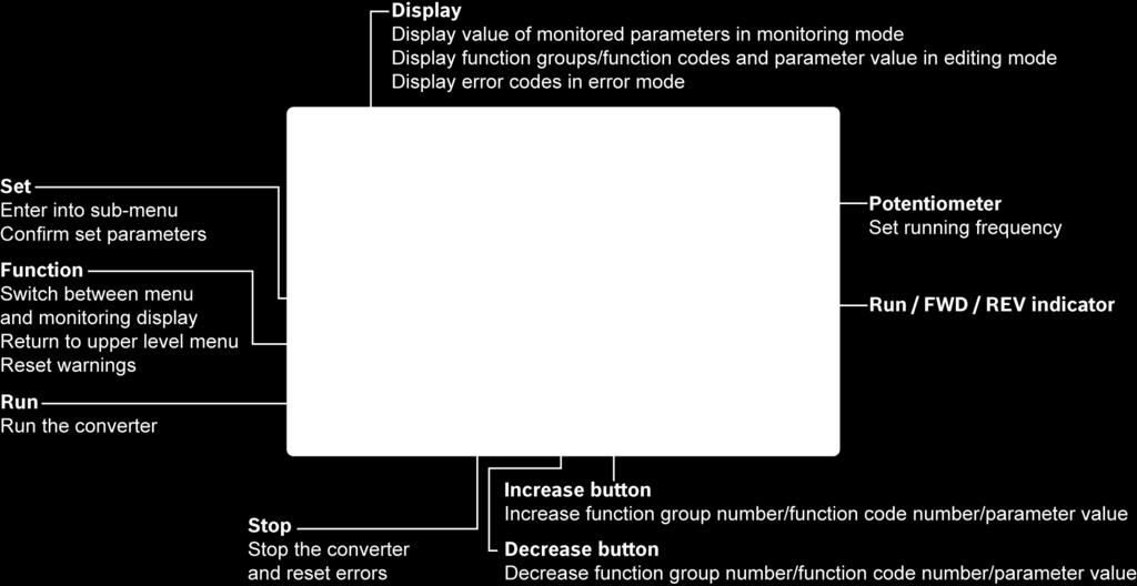
36 3 3.1 LED Panel and Dust Cover LED Panel Fig. 3-1: LED panel 30/91 DOK-RCON03-EFC-X610***-QU12-EN-P

37 3.1.2 Dust Cover Fig. 3-2: Dust cover Frequency Converter EFC x610 are available with Dust Cover instead of LED Panel on demand. To operate frequency converters with Dust Cover, Order one LED Panel additionally, and then set the frequency converters with Parameter replication function. See parameter b0.11. DOK-RCON03-EFC-X610***-QU12-EN-P 31/91
38 3.1.3 LED Indicator Mode Run FWD REV Power 1 Power off Off Off Off Off Ready Off Green / Off Off / Green Red Run (FWD) Green Green Off Red Run (REV) Green Off Green Red Run pending Blinks in green DC-braking at start Direction change dead time Deceleration stop phase (Short green long dark) Blinks in green Green / Off Off / Green Red DC-braking at stop (Short dark long green) Green / Off Off / Green Red Warning with FWD Green Green Off Warning with REV Green Off Green Warning at stop Off Green / Off Off / Green Error Off Green / Off Off / Green Tab. 3-1: LED indicator status Blinks in red (Short dark long red) Blinks in red (Short dark long red) Blinks in red (Short dark long red) Blinks in red (Short red long dark) 1 : Available on dust cover or when neither the LED panel nor the dust cover is installed. The frequency converter stops if FWD and REV commands are active at the same time. 32/91 DOK-RCON03-EFC-X610***-QU12-EN-P

39 3.1.4 Operating Descriptions Fig. 3-3: Operating mode Fig. 3-4: Operating example Digit Shifting Function is provided for fast parameter selection and modification. Please refer to the Operating Instructions for details. DOK-RCON03-EFC-X610***-QU12-EN-P 33/91
 Loc / Rem button: Switch between \"Remote\" & \"Local\". (3) Func button: Enter the parameter group screen and go back to previous screens.")

40 3.2 LCD Panel LCD Panel Introduction Fig. 3-5: LCD panel appearance (1) Navigation button 1. Scroll between parameter and group code 2. Set the parameter value (2) Loc / Rem button: Switch between "Remote" & "Local". (3) Func button: Enter the parameter group screen and go back to previous screens. (4) Stop button: Stop the frequency converter. (5) Run button: Start the frequency converter. (6) Text area: Used for displaying: 1. Parameter monitoring screen 2. Parameter group / Parameter code 3. Parameter name 4. Parameter value and unit 5. Other screens: Error / Warning display screen, welcome screen, customer information message screen (7) Run / Stop status: It displays information regarding run / stop and forward / reverse state of the frequency converter. Details are shown in the table below. 34/91 DOK-RCON03-EFC-X610***-QU12-EN-P
41 Frequency converter status Running at 0 Hz (set RefDir: FWD) Running at 0 Hz (set RefDir: REV) Frequency converter in RUN state (set RefDir: REV) Frequency converter in RUN state (set RefDir: FWD) Details : Blinking : Invisible : Invisible : Invisible : Blinking : Invisible : Invisible : Shown solid, not blinking : Invisible : Shown solid, not blinking : Invisible : Invisible Tab. 3-2: Frequency converter status (8) Error / Warning information: Error / Warning code will be displayed in this sector. Please refer to chapter 4 "Diagnosis" on page 87 for details. (9) Permanent monitoring: By default, its display as "Actual output frequency" is set by parameter U2.09. Value and unit of parameter will be displayed. (10) Re / Lo: Re stands for 'Remote' and Lo for 'Local'. Its display is set via Loc / Rem button or parameter U2.03. (11) Panel Locked / Unlocked: Panel can be locked by the following ways: Setting [U2.02] to '1', or Pressing Func button with Loc button for longer than 3 s. Panel can be unlocked by the following ways: Setting [U2.02] to '0' (only in communication mode), or Pressing Func button with Loc button for longer than 3 s Operating Example Please follow the steps below to set parameter [b0.10] to '1: Restore to default settings' through LCD panel. 1. Press Func button. 2. Rotate Navigation button to select parameter group b0. 3. Press Navigation button and rotate it to select parameter b Press Navigation button and rotate it to select parameter value '1: Restore to default settings'. 5. Press Navigation button to finish setting. DOK-RCON03-EFC-X610***-QU12-EN-P 35/91
42 3.3 Procedure Checking before Power-on Ambient conditions See chapter 1.2 "Ambient Conditions" on page 1 Installation conditions See chapter 1.3 "Installation Conditions" on page 2 See chapter 2 "Electric Installation" on page 13 Wiring Tab. 3-3: Checking before Power-on EMC requirements must be observed, see details in Operating Instructions All switches must be switched off All loads must be disconnected Checking after Power-on LED panel Dust cover 0.00 is displayed Power indicator is red, see chapter "Dust Cover" on page 31 and chapter "LED Indicator" on page 32 Tab. 3-4: Checking after Power-on Checking Parameters Set [b0.00] = '3: parameters', and then check all start-up parameters. For terminology and abbreviation in the above table, see chapter "Terminology and Abbreviation in Parameter List" on page 42. Code Name Setting range Default Min. Attri. C0.05 Carrier frequency 0K K0: khz 30K K: khz 0K40...4K00: 6k 5K K0 (HD): 6k 5K K0 (ND): 4k 1 Run 30K0...90K0: 4k 110K...160K: 2k C1.05 Motor rated power ,000.0 kw DOM 0.1 Stop C1.06 Motor rated voltage V DOM 1 Stop C1.07 Motor rated current A DOM 0.01 Stop C1.08 Motor rated frequency Hz Stop C1.09 Motor rated speed ,000 rpm DOM 1 Stop 0: Linear C2.00 V/f curve mode 1: Square 2: User-defined 3: V/f separation 0 Stop 36/91 DOK-RCON03-EFC-X610***-QU12-EN-P
43 Code Name Setting range Default Min. Attri. E0.00 First frequency setting source Stop E0.01 First run command source Stop E0.07 Digital setting frequency [E0.09] Hz Run E0.08 Maximum output frequency Hz Stop E0.09 Output frequency high limit [E0.10]...[E0.08] Hz Run E0.10 Output frequency low limit [E0.09] Hz Run 0: Forward/Reverse E0.17 Direction control E0.25 Acceleration / Deceleration curve mode 1: Forward only 2: Reverse only 3: Swap default direction 0: Linear mode 1: S-curve 0 Stop 0 Stop E0.26 Acceleration time ,000.0 s DOM 0.1 Run E0.27 Deceleration time ,000.0 s DOM 0.1 Run 0: Start directly E0.35 Start mode E0.50 Stop mode Tab. 3-5: parameters 1: DC-braking before start 2: Start with speed tracing 3: Automatic start / stop according to setting frequency 0: Decelerating stop 1: Freewheeling stop 1 2: Freewheeling stop 2 0 Stop 0 Stop DOK-RCON03-EFC-X610***-QU12-EN-P 37/91
44 3.3.4 Control the Motor Step Operation Description Rotate the potentiometer counterclockwise 1 Output frequency setting is 0.00 (leftwards) to the greatest extent 2 Press <Run> button Control command active, 0.00 is displayed Rotate the potentiometer clockwise (rightwards) slowly and till 5.00 is displayed The motor starts to run Recommended operation: 3 Observe the running status: If the motor runs in the correct direction If the motor runs steadily Stop the motor immediately by switching off the power if any abnormality occurs If there is any abnormal noise or problem Restart commissioning only after error causes have been removed 4 Rotate the potentiometer clockwise The motor accelerates 5 Rotate the potentiometer counterclockwise The motor decelerates 6 Press <Stop> button Stop command active, the motor stops 7 Check parameters without load Settings according to actual applications 8 Check parameters with load Settings according to actual applications Tab. 3-6: Motor controlling procedure EFC x610 has no internal contactor, and will be energized once the power supply is connected. When the Run button is pressed down (or 'Control by terminals' is activated), the frequency converter will generate output. By default, EFC x610 is set as: The frequency converter is started or stopped by the operating panel control. The output frequency is set by the potentiometer on the operating panel. After powering on, please confirm: The setting frequency is displayed (no error display). The monitoring parameter is consistent with the actual situation. By default, the frequency converter displays Output frequency in run status and Setting frequency in stop status as the monitoring parameters. You may change them to other parameters as described in parameters U1.00 and U1.10. The factory defaults are based on standard applications with standard motors. For frequency converters with dust cover, it is recommended to install an LED panel to perform the above operations. 38/91 DOK-RCON03-EFC-X610***-QU12-EN-P
45 3.3.5 Motor Parameters Auto-Tuning The application with asynchronous motor(asm) When SVC control is used or in the condition of V/f control demanding for higher control performance, motor parameter auto-tuning is necessary. Two modes of auto-tuning are available, static auto-tuning and rotational auto-tuning. The former mode is mainly used for V/f control and the latter is used mainly for SVC control. Check and make sure the following points before auto-tuning: The motor is in standstill and not at high temperature. The power rating of the frequency converter is close to that of the motor. Set C C1.10 based on motor nameplate data. If the power factor data is unavailable on the nameplate, keep the default setting of C1.10. Set E0.08 according to motor parameters and actual application conditions. Disconnect the load from the motor shaft for rotational auto-tuning. Set auto-tuning mode and start motor parameter auto-tuning: Set the following parameter according to the control mode of the frequency converter and the application situation. Code Name Setting range Default Min. Attri. C1.01 Motor parameter tuning Stop 0: Inactive. The auto-tuning function is by default inactive. 1: Static auto-tuning. This mode is suggested to be used for V/f control. It can also be used for SVC control when the load cannot be disconnected. 2: Rotational auto-tuning (suggested to be used for SVC control) Press the <Run> button on the operating panel to start auto-tuning. In the process of auto-tuning, a status code 'tune' will be displayed on the operating panel. When the auto-tuning process is complete, the status code disappears and the settings of the following parameters will be obtained automatically: Static auto-tuning Rotational auto-tuning Parameters obtained by auto-tuning C1.12: Motor rated slip frequency C1.13: Motor inertia mantissa 1 C1.14: Motor inertia exponent 1 C1.20: Motor no-load current C1.21: Stator resistance C1.22: Rotor resistance C1.23: Leakage inductance C1.24: Mutual inductance DOK-RCON03-EFC-X610***-QU12-EN-P 39/91
46 Static auto-tuning Rotational auto-tuning Parameters obtained by auto-tuning C3.00: Speed loop proportional gain 1 C3.01: Speed loop integral time 1 C3.05: Current loop proportional gain C3.06: Current loop integral time Tab. 3-7: Parameters obtained by auto-tuning 1 : Only applicable for EFC The application with permanent magnetized synchronous motor (PMSM) When SVC control is used for the control of PMSM, motor parameters auto-tuning function shall be adopted. Two modes of auto-tuning are available, i.e. static auto-tuning and rotational auto-tuning. Before running parameter auto-tuning on synchronous motor, make sure to set both motor type C1.00 and motor nameplate parameters correctly. Check and make sure the following points before auto-tuning: The motor is in standstill and not at high temperature. The power rating of the frequency converter is close to that of the motor. Set C1.05, C1.07, C1.09, C1.11 based on motor nameplate data. Set E0.08, E0.09 according to motor parameters and actual application conditions. Disconnect the load from the motor shaft for rotational auto-tuning. Set auto-tuning mode and start motor parameter auto-tuning: Set the following parameter according to the control mode of the frequency converter and the application situation: Code Name Setting range Default Min. Attri. C1.01 Motor parameter tuning Stop 0: Inactive It s recommended to run static auto-tuning or rotational auto-tuning for PMSM. 1: Static auto-tuning Static auto-tuning shall be used when the motor load is not removable. It s necessary to input inertia value manually in order to achieve the best control effect. 2: Rotational auto-tuning 40/91 DOK-RCON03-EFC-X610***-QU12-EN-P
47 In condition the motor load is removable, it s recommended to move the load and the motor away and run rotational auto-tuning. This method allows the acquisition of all the motor and control parameters that are needed for the vector control and thus enable the best vector control effect. Press the <Run> button on the operating panel when the setting is finished for auto-tuning. In the process of auto-tuning, a status code 'tune' will be displayed on the operating panel. When the auto-tuning process is completed, the status code disappears and the settings of the following parameters will be obtained automatically: Static auto-tuning Rotational auto-tuning Parameters obtained by auto-tuning C1.13: Motor inertia mantissa C1.14: Motor inertia exponent C1.20: Motor no-load current C1.21: Stator resistance C1.23: Leakage inductance C3.05: Current loop proportional gain C3.06: Current loop integral time C3.00: Speed loop proportional gain 1 C3.01: Speed loop integral time 1 Tab. 3-8: Parameters obtained by auto-tuning DOK-RCON03-EFC-X610***-QU12-EN-P 41/91
48 3.4 Parameter List Terminology and Abbreviation in Parameter List Code: Function / parameter code, written in bx.xx, Cx.xx, Ex.xx, Fx.xx, Hx.xx, Ux.xx, dx.xx Name: Parameter name Default: Factory default Min.: Minimum setting step Attri.: Parameter attribute Run: Parameter setting can be modified when the converter is in run or stop status. Stop: Parameter setting can only be modified when the converter is in stop status. Read: Parameter setting is read-only and cannot be modified. DOM: Depends on model [bx.xx], [Cx.xx], [Ex.xx], [Fx.xx], [Hx.xx], [Ux.xx], [dx.xx]: Function / parameter values 42/91 DOK-RCON03-EFC-X610***-QU12-EN-P
49 3.4.2 Group b: System Parameters b0: Basic system parameters Code Name Setting range Default Min. Attri. b0.00 Access authority setting b0.09 Parameter initialization setting b0.10 Parameter initialization b0.11 Parameter copy b0.12 Parameter set selection 0: Basic parameters 1: Standard parameters 2: Advanced parameters 3: parameters 4: Modified parameters 1: Base device and non fieldbus options 2: Fieldbus options 3: Base device, non fieldbus and fieldbus options 0: Inactive 1: Restore to default settings 2: Clear error record 0: Inactive 1: Backup parameters to panel 2: Restore parameters from panel 0: Parameter set 1 active 1: Parameter set 2 active 0 Run 1 Stop 0 Stop 0 Stop 0 Stop b0.20 User password , Run b0.21 Manufacturer password , Run DOK-RCON03-EFC-X610***-QU12-EN-P 43/91
50 3.4.3 Group C: Power Parameters C0: Power control parameters Code Name Setting range Default Min. Attri. C0.00 C0.01 Control mode (EFC 5610 only) Normal / Heavy duty setting 1 C0.05 Carrier frequency C0.06 C0.10 C0.11 C0.15 C0.16 C0.24 C0.25 Carrier frequency automatic adjustment Automatic voltage stabilization 0: V/f control 1: Sensorless vector control 2: Vector control with encoder (only for EFC5610) 0: ND (Normal duty) 1: HD (Heavy duty) 0K K0: khz 30K K: khz 0: Inactive 1: Active 2: Fixed carrier frequency 0: Always active 1: Always inactive 2: Inactive only during deceleration 0K40...4K00: 6k 0 Stop 1 Stop 5K K0 (HD): 6k 5K K0 (ND): 4k 30K0...90K0: 4k 110K...160K: 2k Automatic voltage stabilization reference 3P 200 VAC: V 1P 200 VAC: V 220 voltage 3P 400 VAC: V 380 Brake chopper start voltage 2 1P 200 VAC: V 3P 200 VAC: V 1 Run 1 Stop 0 1 Stop 385 3P 400 VAC: V Stop 1 Stop Brake chopper duty cycle % Stop Stall overvoltage hysteresis voltage Overvoltage prevention mode V 1P 200 VAC: 30 3P 200 VAC: 30 3P 400 VAC: 50 1 Stop Stop 44/91 DOK-RCON03-EFC-X610***-QU12-EN-P
51 Code Name Setting range Default Min. Attri. C0.26 C0.27 C0.28 C0.29 C0.30 C0.40 C0.41 C0.42 C0.43 C0.44 Stall overvoltage prevention level Stall overcurrent 1P 200 VAC: V 3P 200 VAC: V 385 3P 400 VAC: V Stop prevention level %...[C2.42] Stop Phase loss protection mode Converter overload pre-warning level Converter overload pre-warning delay Power loss ridethrough mode Power loss ridethrough recovery delay Power loss ridethrough action voltage Power loss ridethrough recover voltage Run % Stop s Stop 0: Inactive; 1: Output disabled 2: Regain kinetic energy 3: Regain kinetic energy, decelerate to stop 0 Stop s Stop 1P 200 VAC: V 3P 200 VAC: V 240 3P 400 VAC: V 440 1P 200 VAC: V 3P 200 VAC: V 250 3P 400 VAC: V Stop 1 Stop Power loss ridethrough deceleration to ,000.0 s Stop stop time C0.50 Fan control 0: Automatically controlled 1: Always on 2: On when converter run 0 Run C0.51 Fan total running time ,535 h 0 1 Read C0.52 Fan maintenance time ,535 h (0: Inactive) 0 1 Stop C0.53 Fan total running time reset 0: Inactive; 1: Active Resets to '0' after action is executed 1 : this parameter is only available with models of 5K50 and above. 0 Run 2 : the parameters are only available with models of 22K0 and below. DOK-RCON03-EFC-X610***-QU12-EN-P 45/91
52 3 : percentage of frequency converter rated current. Setting range of C0.25: 0: Both disabled 1: Stall overvoltage protection enabled, resistor braking disabled 2: Stall overvoltage protection disabled, resistor braking enabled 3: Stall overvoltage protection enabled, resistor braking enabled Setting range of C0.28: 0: Both input and output phase loss protection active 1: Only input phase loss protection active 2: Only output phase loss protection active 3: Both input and output phase loss protection inactive 46/91 DOK-RCON03-EFC-X610***-QU12-EN-P
53 C1: Motor and system parameters Code Name Setting range Default Min. Attri. C1.00 Motor type C1.01 Motor parameter tuning C1.02 Expert mode 0: Asynchronous motor 1: Synchronous motor (only for EFC 5610) 0: Inactive 0 Stop 1: Static auto-tuning 0 Stop 2: Rotational auto-tuning 1 0: Standard mode 1: Expert mode 0 Stop C1.05 Motor rated power ,000.0 kw DOM 0.1 Stop C1.06 Motor rated voltage V DOM 1 Stop C1.07 Motor rated current A DOM 0.01 Stop C1.08 Motor rated frequency Hz Stop C1.09 Motor rated speed ,000 rpm DOM 1 Stop C1.10 Motor rated power factor 0.00: Automatically identified : Power factor setting Stop C1.11 Motor poles Stop C1.12 Motor rated slip frequency Hz DOM 0.01 Stop C1.13 Motor inertia mantissa ,000 DOM 1 Stop C1.14 Motor inertia exponent DOM 1 Stop C1.15 Torque constant DOM 0.01 Stop C1.20 Motor no-load current [C1.07] A DOM 0.01 Stop C1.21 Stator resistance Ω DOM 0.01 Stop C1.22 Rotor resistance Ω DOM 0.01 Stop C1.23 Leakage inductance mh DOM 0.01 Stop C1.24 Mutual inductance ,000.0 mh DOM 0.1 Stop C1.25 Rotor leakage inductance DOM 0.01 Stop C1.69 Motor thermal model protection setting 0: Inactive 1: Active 0 Stop C1.70 Motor overload pre-warning level % Run C1.71 Motor overload pre-warning delay s Run DOK-RCON03-EFC-X610***-QU12-EN-P 47/91
54 Code Name Setting range Default Min. Attri. C1.72 Motor thermal sensor type C1.73 C1.74 Motor thermal sensor protection level Motor thermal model protection time constant 0: KTY84/130 2: PT100 3: PT1000 4: TDK G1551_8320 (NTC) 0 Stop Stop min DOM 0.1 Stop C1.75 Low speed derating frequency Hz Run C1.76 Zero speed load % Run 1 : ONLY for EFC 5610, and motor load must be decoupled before rotational auto-tuning. 48/91 DOK-RCON03-EFC-X610***-QU12-EN-P
55 C2: V/f control parameters Code Name Setting range Default Min. Attri. C2.00 V/f curve mode 0: Linear 1: Square 2: User-defined 3: V/f separation 0 Stop C2.01 V/f frequency [C2.03] Hz Stop C2.02 V/f voltage % Stop C2.03 V/f frequency 2 [C2.01]...[C2.05] Hz Stop C2.04 V/f voltage % Stop C2.05 V/f frequency 3 [C2.03]...[E0.08] Hz Stop C2.06 V/f voltage % Stop C2.07 Slip compensation factor % 0 1 Run C2.08 C2.09 C2.10 C2.11 C2.12 V/f separation output voltage source selection V/f separation output voltage digital setting V/f separation output voltage acceleration time V/f separation output voltage deceleration time V/f separation stop mode selection 0: Panel potentiometer 1: Panel button setting 2: AI1 analog input 10: X5 pulse input 20: Communication (Modbus 0x7F0B/Fieldbus extension card H0.50) 22: Digital setting 23: Voltage PID control 22 Stop % Run ,000.0 s Run ,000.0 s Run 0: Voltage and frequency decelerates independently 1: Voltage decelerates to zero, then frequency decelerates to zero 0 Run C2.13 V/f separation boost factor Run C Hz output mode 0: No output 1: Standard 1 1 Stop DOK-RCON03-EFC-X610***-QU12-EN-P 49/91
56 Code Name Setting range Default Min. Attri. C2.21 Torque boost setting 0.0 %: Automatic boost %: Manual boost DOM 0.1 Run C2.22 Automatic torque boost factor % 50 1 Run C2.23 Heavy load stabilization setting C2.24 Light load oscillation damping factor C2.25 Light load oscillation damping filter factor C2.40 Current limitation mode 0: Inactive 1: Active 1 Run 0...5,000 % 0 1 Run ,000 % Run 0: Always inactive 1: Inactive at constant speed 2 Stop 2: Active at constant speed C2.42 Current limitation level 2 [C0.27] % Stop C2.43 Current limitation proportional gain DOM Stop C2.44 Current limitation integral time DOM Stop 1 : percentage of motor rated voltage [C1.06]. 2 : percentage of frequency converter rated current. 50/91 DOK-RCON03-EFC-X610***-QU12-EN-P
57 C3*: Vector control parameters Code Name Setting range Default Min. Attri. C3.00 Speed loop proportional gain DOM 0.01 Run C3.01 Speed loop integral time ms DOM 0.01 Run C3.02 Speed loop proportional gain DOM Run C3.03 Speed loop integral time ms DOM Run C3.04 Speed observer harmonics damping factor Stop C3.05 Current loop proportional gain ,000.0 DOM 0.1 Run C3.06 Current loop integral time ms DOM 0.01 Run C3.10 Speed loop switching frequency [C3.11] Stop C3.11 Speed loop switching frequency 2 [C3.10]...[C1.08] Stop C3.20 Low speed torque limitation % Stop C3.21 Encoder speed filter time Stop C3.22 Encoder commutation offset Stop C3.25 Speed monitor timeout s Stop C3.26 C3.38 C3.39 Speed monitor max. speed difference Forward frequency limitation at torque control mode Reverse frequency limitation at torque control mode C3.40 Torque control mode C3.41 Torque reference channel Hz Stop [E0.09] Run [E0.09] Run 0: Activated by digital inputs 1: Always active 2: Communication (Bit 8 of Modbus 0x7F00) (Bit 9 of extension card H0.00) 0: AI1 analog input 1: AI2 analog input 2: Panel potentiometer 3: EAI1 analog input 4: Pulse input via DI5 5: Parameter setting C3.46 6: Communication (Modbus 0x7F02/Fieldbus extension card H0.12) 7: EAI2 analog input 0 Stop 0 Stop DOK-RCON03-EFC-X610***-QU12-EN-P 51/91
The Drive & Control Company. Frequency Converter. VFC 3610 / VFC 5610 Series. Quick Start Guide R Edition 15
 The Drive & Control Company Frequency Converter VFC 3610 / VFC 5610 Series Quick Start Guide R912005518 Edition 15 Bosch Rexroth AG VFC 3610 / VFC 5610 Record of Revision Edition Release Date Notes DOK-RCON04-VFC-X610***-QU06-EN-P
The Drive & Control Company. Frequency Converter. VFC 3610 / VFC 5610 Series. Quick Start Guide R Edition 10
 The Drive & Control Company Frequency Converter VFC 3610 / VFC 5610 Series Quick Start Guide R912005518 Edition 10 Bosch Rexroth AG VFC 3610 / VFC 5610 Record of Revision Edition Release Date Notes DOK-RCON04-VFC-X610***-QU01-EN-P
Rexroth Frequency Converter
 The Drive & Control Company Rexroth Frequency Converter Fe Series Instruction Manual (Quick Start) R912004884 Edition 04 Record of Revision Edition Release Date Notes DOK-RCON01-FE*********-IN02-EN-P 2013.11
Rexroth Frequency Converter Fe
 Electric Drives Linear Motion and and Controls Hydraulics Assembly Technologies Pneumatics Service Rexroth Frequency Converter Fe R912004884 Edition 02 Instruction Manual (Quick Start) Record of Revision
TECO F510 Inverter. Quick Start Guide. Step 1. Supply & Motor connection
 Quick Start Guide TECO F510 Inverter This guide is to assist you in installing and running the inverter and verify that it is functioning correctly for it s main and basic features. For detailed information
TAC ATV38, IP55. Variable Speed Drives for Asynchronous Motors. 3-phase. 380/460 V, Hz
 TAC ATV8, IP55 Variable Speed Drives for Asynchronous Motors. -phase. 80/460 V, 50-60 Hz E-60-24 24 May 2004 ATV 8 IP55 drives are specifically designed for pump and fan applications powered by a three-phase
Operating Instructions
 4XH35QB151210 Small General Frequency Converter Operating Instructions 220V 0.75KW 5.5KW 400V 0.75KW 15KW Please read the instruction carefully and understand the contents so that it can be installed and
Invertek Optidrive E3 Frequency Inverter (IP20, 3ph output) Easy Start Guide
 Easy Start Guide") Invertek Optidrive E3 Frequency Inverter (IP20, 3ph output) Easy Start Guide The Invertek Optidrive E3 Frequency Inverter range is available to order from inverterdrive.com This guide is intended to complement
Invertek Optidrive E3 Frequency Inverter (IP20, 3ph output) Easy Start Guide The Invertek Optidrive E3 Frequency Inverter range is available to order from inverterdrive.com This guide is intended to complement
EFC 3600 Frequency converter for higher energy efficiency and improved process control
 EFC 3600 Frequency converter for higher energy eiciency and improved process control 2 Valuable energy used responsibly Rising energy costs and increasing demands on the environmentally sound products
Index 2. G Gain settings 4 31 Glossary of terms A 2 Grommets 2 13
 Index A A Group functions 3 9 AC reactors 5 3 Acceleration 1 15, 3 8 characteristic curves 3 26 second function 3 24 two-stage 4 19 Acceleration stop function 3 21 Access levels 3 5, 3 36, 4 25 Access
ATV12HU22M2. Main. Range of product Altivar 12. Component name Quantity per set Set of 1. Built-in fan. Motor power hp Communication port protocol
 Product datasheet Characteristics ATV12HU22M2 Complementary Main Range of product Altivar 12 Product or component type Product destination Product specific application Assembly style Component name Variable
HPVFP High Performance Full Function Vector Frequency Inverter
 Advanced User Manual HPVFP High Performance Full Function Vector Frequency Inverter HP VER 1.00 1. HPVFP Parameter Set Overview...3 1.1. About this section...3 1.2. Parameter Structure Overview...3 1.3.
ATV12H018F1 variable speed drive ATV kW hp V - 1ph
 Characteristics variable speed drive ATV12-0.18kW - 0.25hp - 100..120V - 1ph Main Range of product Altivar 12 Product or component type Product destination Product specific application Assembly style Component
ATV12H037F1 variable speed drive ATV kW hp V - 1ph - with heat sink
 Characteristics variable speed drive ATV12-0.37kW - 0.55hp - 100..120V - 1ph - with heat sink Main Range of product Altivar 12 Product or component type Product destination Product specific application
ATV12HU40M3 variable speed drive ATV12-4kW - 5hp V - 3ph - with heat sink
 Characteristics variable speed drive ATV12-4kW - 5hp - 200..240V - 3ph - with heat sink Main Range of product Altivar 12 Product or component type Product destination Product specific application Assembly
VFD - D700 Series Specifications. The latest low-cost variable speed control solution for centrifugal pumps.
 VFD - D700 Series Specifications The latest low-cost variable speed control solution for centrifugal pumps. Built-in PID Control to maintain pressure, flow, measured value, and much more 125% overload
D SERIES EM16 IP 20 / NEMA 1 & IP 66 / NEMA 4X COMPACT VECTOR CONTROL DRIVE EM 16 COMPACT VECTOR CONTROL DRIVE
 D SERIES EM16 IP 20 / NEMA 1 & IP 66 / NEMA 4X COMPACT VECTOR CONTROL DRIVE EM 16 COMPACT VECTOR CONTROL DRIVE 1 2 SERIES 1 2 pag. 4 pag. 5 Applications Model identification 3 pag. 5 4 pag. 6 Capacity
System configuration. Ratings 400 V Class three-phase 90 to 800 kw 690 V Class three-phase 90 to 1000 kw SX-D. Frequency inverters.
 ~ ~ SX High performance Vector Control IP54 full range. Compact design & Robustness Built-in Filter according to C3 Class Built-in Fusses (From 200 kw) Safety according EN13849-1 and EN62061 standards
Frequency Converter Fv vector control converters for universal applications
 Frequency Converter Fv vector control converters for universal applications 2 Our goal: To be world market leader in providing benefits to customers With our broad portfolio of products and services we
Rexroth Frequency Converter Fe 0.75 kw to 7.5 kw / 400 VAC
 Electric Drives and Controls Hydraulics Linear Motion and Assembly Technologies Pneumatics Rexroth Frequency Converter Fe 0.75 kw to 7.5 kw / 400 VAC Simple, scalable and economical Service Bosch Rexroth
ATV12H037F1 variable speed drive ATV kW hp V - 1ph - with heat sink
 Characteristics variable speed drive ATV12-0.37kW - 0.55hp - 100..120V - 1ph - with heat sink Product availability : Stock - Normally stocked in distribution facility Price* : 191.76 USD Main Range of
Goodrive inverter for air compressor. Preface
 Goodrive 300-01 Series Inver ter for Air Compressor GD300-01-037G-4 Preface Preface Goodrive300-01 series inverter for air compressor is developed based on Goodrive300 hardware platform and can be widely
Ambient Conditions Storage Conditions Installation Minimum Clearances and Air Flow...2 3
 CHAPTER INSTALLATION 2 AND WIRING Contents of this Chapter... Ambient Conditions..............................2 2 Storage Conditions...............................2 2 Installation.....................................2
6.9 Jump frequency - Avoiding frequency resonance
 E581595.9 Jump frequency - Avoiding frequency resonance : Jump frequency : Jumping width Function Resonance due to the natural frequency of the mechanical system can be avoided by jumping the resonant
GS1 Parameter Summary Detailed Parameter Listings...4 9
 CHAPTER AC DRIVE 4 PARAMETERS Contents of this Chapter... GS1 Parameter Summary...............................4 2 Detailed Parameter Listings..............................4 9 Motor Parameters.........................................4
Preface. Notes. Thank you for purchasing the VTP8 series AC drive.
 Preface Thank you for purchasing the VTP8 series AC drive. The VTP8 series AC drive is a general-purpose high-performance current vector control AC drive. It can implement the control of asynchronous motor.
S11 Adjustable Speed Drive Engineering Specification
 PART 1 - GENERAL 1.0 Scope This specification shall cover Toshiba S11 AC Variable Frequency Drives, 6 pulse for 3- phase 200-240VAC, 380-500VAC and single phase 200V to 240VAC. 1.1 References A. National
NX series Constant and variable torque Variable Speed Drives for induction motors
 Honeywell All in One Application Manual NX series Constant and variable torque Variable Speed Drives for induction motors Subject to changes without notice CONTENTS NX "All in One" APPLICATION MANUAL INDEX
SX (400 V) System configuration
 System configuration") ~ ~ SX (400 V) High performance Vector Control IP54 full range. Compact design & Robustness Built-in Filter according to C3 Class Built-in Fuses (From 200 kw) Safety according EN13849-1 and EN62061 standards
~ ~ SX (400 V) High performance Vector Control IP54 full range. Compact design & Robustness Built-in Filter according to C3 Class Built-in Fuses (From 200 kw) Safety according EN13849-1 and EN62061 standards
FREQUENCY INVERTER VFR-013 QUICK START GUIDE
 FREQUENCY INVERTER VFR-013 QUICK START GUIDE Inoréa Automation & Industry 9 rue du Lugan 33130 BEGLES www.inorea.com Table of contents 1. PEOPLE SAFETY... 3 2. MATERIAL SAFETY... 3 3. NAME PLATE... 4 a.
SX (400V) System configuration
 System configuration") ~ ~ SX (400V) High performance Vector Control IP54 full range. Compact design & Robustness Built-in Filter according to C3 Class Built-in Fusses (From 200 kw) Safety according EN13849-1 and EN62061 standards
~ ~ SX (400V) High performance Vector Control IP54 full range. Compact design & Robustness Built-in Filter according to C3 Class Built-in Fusses (From 200 kw) Safety according EN13849-1 and EN62061 standards
ADC5000 SERIES. AC/DC Switch Mode Power Supplies and Rectifiers for Industrial and Telecom Applications. 60W, 125W and 250 W
 ADC5000 SERIES AC/DC Switch Mode Power Supplies and Rectifiers for Industrial and Telecom Applications 60W, 125W and 250 W Input voltage 230/115 VAC voltages 12, 24, 36 or 48 VDC Statistical MTBF >3 000
ADTECH Solar inverter
 ADTECH Solar inverter 1. Product description Thank you very much for your selection of special solar inverter launched by ADTECH (SHENZHEN) TECHNOLOGY CO., LTD. Solar energy special inverter is designed
SX (690 V) System configuration
 System configuration") SX (690 V) High performance Vector Control IP54 full range Compact design & Robustness Built-in Filter according to C3 Class Built-in Fuses (From 200 kw) Safety according EN13849-1 and EN62061 standards
SX (690 V) High performance Vector Control IP54 full range Compact design & Robustness Built-in Filter according to C3 Class Built-in Fuses (From 200 kw) Safety according EN13849-1 and EN62061 standards
NX Series Inverters. HVAC Pocket Programming Guide
 NX Series Inverters HVAC Pocket Programming Guide HVAC Pocket Programming Guide HVAC Pocket Programming Guide / Contents This guide provides a single reference document for the user of NXL HVAC (product
VF-nC1 Adjustable Speed Drive Engineering Specification
 PART 1 - GENERAL 1.0 Scope This specification shall cover Toshiba VF-nC1 AC Variable Frequency Drives, 6 pulse for 100V single-phase 0.1 to 0.75kW, 200V single-phase 0.2 to 2.2kW and 200V threephase 0.1
Type CP-S, CP-C & CP-A Switch mode
 Switch mode power CP-S, CP-C & CP-A Switch mode Characteristics CP-S and CP-C range Output current 5 A, 10 A and 20 A Integrated power reserve of up to 50 % 5 A and 10 A devices with pluggable connecting
This operation manual is intended for users with basic knowledge of electricity and electric devices.
 This operation manual is intended for users with basic knowledge of electricity and electric devices. Safety Information Safety Information Read and follow all safety instructions in this manual precisely
HV580L Series Frequency Inverter User Manual
 User Manual HNC Electric Limited Contents Contents... 2 Chapter 1 Safety Information and Precautions... 4 1.1 Safety Information... 4 1.2 General Precautions... 7 Chapter 2 Product Information... 10 2.1
CHAPTER AC DRIVE PARAMETERS. In This Chapter...
 CHAPTER AC DRIVE 4 PARAMETERS In This Chapter... GS2 Parameter Summary....................4 2 Detailed Parameter Listings.................4 11 Motor Parameters........................4 11 Ramp Parameters.........................4
VFSC9 ELECTRONIC SPEED CONTROLLER. Mounting and operating instructions
 ELECTRONIC SPEED CONTROLLER Mounting and operating instructions Table of contents SAFETY AND PRECAUTIONS 3 PRODUCT DESCRIPTION 4 ARTICLE CODES 4 INTENDED AREA OF USE 4 TECHNICAL DATA 4 STANDARDS 5 WIRING
HV580 Series Frequency Inverter User Manual
 User Manual HNC Electric Limited Contents Contents...2 Chapter 1 Safety Information and Precautions...4 1.1 Safety Information... 4 1.2 General Precautions...7 Chapter 2 Product Information...10 2.1 Designation
User's Guide for type ACS55 AC Drives from 0.18 to 2.2 kw
 EN 5 User's Guide for type ACS55 AC Drives from 0.18 to 2.2 kw English EN EN 7 Safety instructions Altering the DIP switches will affect the function and performance of ACS55. Check that the changes will
NSD Safety Mat Controller Modules Both Modules are compliant to OSHA & ANSI Standards - EN ISO EN EN 81-1 EN NSD VDC
 Datasheet NSD Safety Mat Controller Modules Both Modules are compliant to OSHA & ANSI Standards - EN ISO 13849-1 EN 62061 EN 81-1 EN 50156-1 Approvals NSD-3580 24 VDC NSD-3590 115 TO 230 VAC Technical
Contents. Safety Information and Precautions Product Information Operation Panel (Keypad & Display) Quick Setup...
 Quick Setup...") Contents Safety Information and Precautions...2 1. Product Information...4 1.1 Nameplate and Designation Rule... 4 1.2 General Specifications... 5 1.3 Environment... 9 2 Wiring... 10 2.1 Typical System
Contents Safety Information and Precautions...2 1. Product Information...4 1.1 Nameplate and Designation Rule... 4 1.2 General Specifications... 5 1.3 Environment... 9 2 Wiring... 10 2.1 Typical System
INDEX. i 1. B Braking Resistor Dimensions: A 24 Braking Resistors: A 20 Braking Units: A 20. DURAPULSE AC Drive User Manual
 INDEX A AC Drive Cover: 1 6 Dimensions: 2 4 External Parts and Labels: 1 6 Heat Sink Fins: 1 6 Input Mode Switch (Sink/Source): 1 6 Introduction to DuraPulse GS3 AC drive: 1 3 Keypad: 1 6 Model Number
MD310 Quick Start Manual. General-Purpose AC Drive
 MD310 Quick Start Manual General-Purpose AC Drive ersion 0.1 Dated 14 th OCT, 2013 CONTENTS CHAPTER 1 PRODUCT INFORMATION... 1 1.1 Designation... 1 1.2 Nameplate... 1 1.3 General Specifications... 2 CHAPTER
Temperature monitoring relays CM-TCS Monitoring relays for monitoring temperatures with a PT100 sensor (2- or 3-wire connection)
") Data sheet Temperature monitoring relays CM-TCS Monitoring relays for monitoring temperatures with a PT100 sensor (2- or 3-wire connection) The temperature monitoring relays CM-TCS monitor overtemperature,
Data sheet Temperature monitoring relays CM-TCS Monitoring relays for monitoring temperatures with a PT100 sensor (2- or 3-wire connection) The temperature monitoring relays CM-TCS monitor overtemperature,
D SERIES LM16. COMPACT DRIVE V/f and SLV CONTROL. LM16 COMPACT DRIVE V/f and SLV CONTROL
 D SERIES LM16 COMPACT DRIVE V/f and SLV CONTROL LM16 COMPACT DRIVE V/f and SLV CONTROL 1 2 SERIES 1 2 page 4 page 6 Introduction Fields of application 3 page 7 4 page 8 Designation Product offer 5 6 page
Manual Overview...1 2
 GETTING STARTED CHAPTER 1 Contents of this Chapter... Manual Overview.....................................1 2 Overview of this Publication..................................1 2 Who Should Read This Manual...............................1
Drive IT Low Voltage Drives. User's Guide for type ACS50 AC Drives from 0.18 to 0.75 kw
 Drive IT Low Voltage Drives User's Guide for type ACS50 AC Drives from 0.18 to 0.75 kw ACS50 User s Guides in other languages can be found from internet: http://www.abb.com. Enter ACS50 UG into the Search
vacon nx all in one application manual ac drives Phone: Fax: Web: -
 vacon nx ac drives all in one application manual vacon 1 INDEX Document ID:DPD00903A Revision release date: 30.3.2012 1. Basic Application...5 1.1. Introduction...5 1.1.1. Motor protection functions in
DORNA TECHNOLOGY CO., LTD. DLA1 Series Inverter. User Manual (V1.0)
") DORNA TECHNOLOGY CO., LTD DLA1 Series Inverter User Manual (V1.0) Table of Contents 1 Summary... 4 1.1 Name plate... 4 1.2 Product series... 5 1.3 Technical standards... 6 1.4 Peripheral Electrical Devices
DORNA TECHNOLOGY CO., LTD DLA1 Series Inverter User Manual (V1.0) Table of Contents 1 Summary... 4 1.1 Name plate... 4 1.2 Product series... 5 1.3 Technical standards... 6 1.4 Peripheral Electrical Devices
ESR. The Dynamic Solution. Applications. Products, Consultation, and Service. ESR Pollmeier GmbH
 Analog AC servo drive systems with sinusoidal commutation Servo drives in compact design, 230 V AC mains connection Servo motors with high power density up to 5.0 Nm / 1.1 kw Components of the TrioDrive
smd frequency inverter
 S03B These Instructions contain important technical data and describe installation, operation and commissioning of the smd frequency inverter. are only valid for smd frequency inverters with software rev
Ametek, Inc. Rotron Technical Products Division. 100 East Erie St., Suite 200 Kent, Ohio User's Guide. Number Revision F
 Ametek, Inc. Rotron Technical Products Division 100 East Erie St., Suite 200 Kent, Ohio 44240 User's 120 Volt, 800 Watt and 240 Volt, 1200 Watt Brushless Motor Drive Electronics 5.7" (145 mm) and 7.2"
8V General information. 2 Order data 8V
 8V05.00-8V05.00- General information Modular mechanical design using plug-in modules Integrated line filter Integrated braking resistor All connections are made using plug-in connectors Integrated electronic
Comp-AC. User s Manual for type ACS 140 frequency converters from 0.12 to 2.2 kw
 Comp-AC User s Manual for type ACS 140 frequency converters from 0.12 to 2.2 kw ACS 140 Frequency Converter User s Manual 3BFE 64273736 R0125 EN Effective: 8.3.2000 2000 ABB Industry Oy Safety Warning!
Altivar 28 drive Altivar 28 enclosed drive
 Telemecanique drive enclosed drive March 00 Characteristics : pages 0 to pages 4 to 2 Dimensions, schemes : pages 24 to 29 Presentation, functions Presentation A frequency inverter for -phase asynchronous
Version number A=standard P=Cold Plate (Frame A only) T=Brake chopper (Frame A only) Input voltage 11=115VAC 21=230VAC 1φ 23=230VAC 3φ 43=400VAC
 T=Brake chopper (Frame A only) Input voltage 11=115VAC 21=230VAC 1φ 23=230VAC 3φ 43=400VAC") Type number key VFD 007 E 43 A Version number A=standard P=Cold Plate (Frame A only) T= (Frame A only) Input voltage 11=115VAC 21=230VAC 1φ 23=230VAC 3φ 43=400VAC VFD-E series Power 007=0.75kW 022=2.2kW
Type number key VFD 007 E 43 A Version number A=standard P=Cold Plate (Frame A only) T= (Frame A only) Input voltage 11=115VAC 21=230VAC 1φ 23=230VAC 3φ 43=400VAC VFD-E series Power 007=0.75kW 022=2.2kW
Variable Frequency Drive / Inverter (0.4 ~ 280kW)
") Variable Frequency Drive / Inverter (0.4 ~ 280kW) & Standard Features Configuration Comparison Comparison Table Enclosure IP00 IP20 NEMA 1 Rating Single phase 0.4 2.2kW 0.4 1.5kW Three phase 0.4 4kW Constant
Variable Frequency Drive / Inverter (0.4 ~ 280kW) & Standard Features Configuration Comparison Comparison Table Enclosure IP00 IP20 NEMA 1 Rating Single phase 0.4 2.2kW 0.4 1.5kW Three phase 0.4 4kW Constant
Power supply CP-D 24/4.2 Primary switch mode power supply
 Data sheet Power supply CP-D 24/4.2 Primary switch mode power supply The CP-D range of modular power supply units in MDRC design (modular DIN rail components) is ideally suited for installation in distribution
A510 INVERTER. 230VClas3~ kW 1-3HP HP kW 1-425HP. 460VClas3~ 575/690VClas3~ 1-270HP INSTRUCTIONMANUAL
 A510 INVERTER INSTRUCTIONMANUAL 230VClas1/3~ 0.75-2.2kW 1-3HP 230VClas3~ 460VClas3~ 575/690VClas3~ 3.7-10kW 5-150HP 0.75-315kW 1-425HP 0.75-20kW 1-270HP Readaloperatinginstructionsbeforeinstaling, connecting(wiring),operating,servicing,orinspecting
Frequency Converter Fe Economical converters for universal applications
 Frequency Converter Fe Economical converters for universal applications 3 4 Frequency Converter Fe Simple, scalable and economical 5 Benefits that impress Including in your industry 6 Easy to use 7 Parameterize
Proximity Sensor Terminology
 The following descriptions refer to the European standard EN 60947-5-2. of 2007. The specifications given here are intended to be minimum performance values described by the standard. Alignment must not
SAFETY INSTRUCTIONS WARNING
 Important User Information Thank you for purchasing LS Variable Frequency Drives! SAFETY INSTRUCTIONS Always follow safety instructions to prevent accidents and potential hazards from occurring. In this
maxon document number:
 maxon document number: 791272-04 1 Table of contents... 2 2 Table of figures... 3 3 Introduction... 4 4 How to use this guide... 4 5 Safety Instructions... 5 6 Performance Data... 6 6.1 Motor data... 6
Power supply CP-D 12/2.1
 2CDC 271 025 F0t07 a OUTPUT ++/ : terminals output Features Rated output voltage 12 V DC Output voltage adjustable via front face potentiometer OUTPUT Adjust Rated output current 2.1 A Rated output power
Power supply CP-T 48/20.0 Primary switch mode power supply
 Data sheet Power supply CP-T 48/20.0 Primary switch mode power supply The CP-T range of three-phase power supply units is the youngest member of ABB s power supply family. In terms of design and functionality,
ROLL TO ROLL FUNCTION MANUAL FR-A (0.4K)-04750(90K)-R2R FR-A (0.4K)-06830(280K)-R2R FR-A (315K)-12120(500K)-R2R
-04750(90K)-R2R FR-A (0.4K)-06830(280K)-R2R FR-A (315K)-12120(500K)-R2R") INVERTER ROLL TO ROLL FUNCTION MANUAL FR-A820-00046(0.4K)-04750(90K)-R2R FR-A840-00023(0.4K)-06830(280K)-R2R FR-A842-07700(315K)-12120(500K)-R2R Roll to Roll Function The FR-A800-R2R inverter has dedicated
INVERTER ROLL TO ROLL FUNCTION MANUAL FR-A820-00046(0.4K)-04750(90K)-R2R FR-A840-00023(0.4K)-06830(280K)-R2R FR-A842-07700(315K)-12120(500K)-R2R Roll to Roll Function The FR-A800-R2R inverter has dedicated
P-SERIES VFD 1-40HP (200~230VAC), 1-400HP (380~480VAC),3Ø Dual Rated for Constant & Variable Torque Integrated PID Control
, 1-400HP (380~480VAC),3Ø Dual Rated for Constant & Variable Torque Integrated PID Control") P-SERIES VFD 1-40HP (200~230VAC), 1-400HP (380~480VAC),3Ø Dual Rated for Constant & Variable Torque Integrated PID Control NEW FIRMWARE MAKES SETUP A SNAP Application based commissioning allows parameters
P-SERIES VFD 1-40HP (200~230VAC), 1-400HP (380~480VAC),3Ø Dual Rated for Constant & Variable Torque Integrated PID Control NEW FIRMWARE MAKES SETUP A SNAP Application based commissioning allows parameters
NICE900 -Door Drive Setup Manual for Asynchronous / Synchronous Motor with Encoder Feedback (Document Release Dt ) Sr. No
 Sr. No") Inova Automation Pvt Ltd., NIBHI Corporate Centre, 3 rd Floor, No.7, CBI Colony, 1 st Main Link Road, Perungudi, Chennai-600096. Ph:-+91 (0)44 4380 0201 Email:- info.inovaindia@inova-automation.com Website:-
Inova Automation Pvt Ltd., NIBHI Corporate Centre, 3 rd Floor, No.7, CBI Colony, 1 st Main Link Road, Perungudi, Chennai-600096. Ph:-+91 (0)44 4380 0201 Email:- info.inovaindia@inova-automation.com Website:-
TETRA COMPACT LOW VOLTAGE BRUSHLESS SERVOMOTORS
 TETRA COMPACT LOW VOLTAGE BRUSHLESS SERVOMOTORS BRUSHLESS TECHNOLOGY FEATURES AND BENEFITS Synchronous brushless servomotor, permanently excited Rated output power from 60W to 800W Maximum servomotor speed
LXM32CD18N4 motion servo drive - Lexium 32 - three-phase supply voltage 208/480V kw
 Product data sheet Characteristics LXM32CD18N4 motion servo drive - Lexium 32 - three-phase supply voltage 208/480V - 1.8 kw Main Range of product Lexium 32 Product or component type Device short name
ADJUSTABLE SPEED DRIVES. AS1 Drive
 ADJUSTABLE SPEED DRIVES AS1 Drive Toshiba s New ASD Product Line The AS1 drive builds on Toshiba s history of supplying powerful, reliable, and versatile drives. We have combined our best drive features
Fan and Pump AC Inverter
 Fan and Pump AC Inverter Key Features for Fan and Pump Applications PID and Auto Energy Saving Functions. Input Phase Loss and Output Phase Loss Protection. LCD Keypad can be used to copy parameter settings
Current monitoring relays CM-SRS.1 For single-phase AC/DC currents
 Data sheet Current monitoring relays CM-SRS.1 For single-phase AC/DC currents The CM-SRS.1 is an electronic current monitoring relay that protects single-phase mains (DC or AC) from over- and undercurrent
CHAPTER 3 WIRING DANGER
 CHAPTER WIRING DANGER Hazardous Voltage Before accessing the AC drive: Disconnect all power to the AC drive. Wait five minutes for DC bus capacitors discharge. Any electrical or mechanical modification
CP-E range Benefits and advantages
 Benefits and advantages Characteristics Output voltages 5 V, 12 V, 2 V, 8 V DC Adjustable output voltages Benefits Signalling output/contact Output currents 0.625 A / 0.75 A / 1.25 A / 2.5 A / A / 5 A
safety Doc: DPD00714C, Released: vacon 1 ONLY A COMPETENT ELECTRICIAN IS ALLOWED TO CARRY OUT THE ELECTRICAL INSTALLATION! 1.
 safety Doc: DPD00714C, Released: 10.28.2011 vacon 1 This quick guide includes the essential steps for easy installation and setup of your Vacon 10 frequency converter. Before commissioning your drive,
PROXIMITY SENSOR TERMINOLOGY
 Never use this desk reference for installation or operation of equipment. Refer to manual for installation and operation instructions. The following descriptions refer to the European standard EN 60947-5-2.
Three-phase monitoring relay CM-PFS
 Data sheet Three-phase monitoring relay CM-PFS The CM-PFS is a three-phase monitoring relay that is used to monitor three phase mains for incorrect phase sequence and phase failure. All devices are available
FUJI Inverter. Standard Specifications
 FUJI Inverter o Standard Specifications Norminal applied motor The rated output of a general-purpose motor, stated in kw. That is used as a standard motor. Rated capacity The rating of an output capacity,
ATSU01N232LT soft starter for asynchronous motor - ATSU01-32 A V KW
 Characteristics soft starter for asynchronous motor - ATSU01-32 A - 200..480V - 7.5..15 KW Main Range of product Product or component type Product destination Product specific application Device short
Current monitoring relays CM-SRS.2 For single-phase AC/DC currents
 Data sheet Current monitoring relays CM-SRS.2 For single-phase AC/DC currents The CM-SRS.2 is an electronic current monitoring relay that protects single-phase mains (DC or AC) from over- and undercurrent
Inverter Drive /Vector Drive Motors & Controls
 H2 Inverter/ Encoderless Vector Inverter Drive /Vector Drive & Controls 3/4 thru 50 180-264 VAC 3 Phase - 50/60 Hz 3/4 thru 60 340-528 VAC 3 Phase - 50/60 Hz 3/4 thru 60 515-660 VAC 3 Phase - 60 Hz HVAC
[ 4 ] Using pulse train input (F01 = 12)
![[ 4 ] Using pulse train input (F01 = 12)](/thumbs/90/102625444.jpg "[ 4 ] Using pulse train input (F01 = 12)") [ 4 ] Using pulse train input (F01 = 12) Selecting the pulse train input format (d59) A pulse train in the format selected by the function code d59 can give a frequency command to the inverter. Three types
[ 4 ] Using pulse train input (F01 = 12) Selecting the pulse train input format (d59) A pulse train in the format selected by the function code d59 can give a frequency command to the inverter. Three types
CHAPTER 8 PARAMETER SUMMARY
 CHAPTER PARAMETER SUMMARY Group 0: System Parameter VFD-V Series 00-00 Identity Code Based on the model type 00-01 Rated Current Display 00-02 Parameter Reset 00-03 00-04 Star-up Display of the Drive Definitions
Manual. Frequency Inverter. Series KFU 2- / 4- 0,55 to 3,0 kw 230 V KFU 2-0,55 to 132 kw 400 V KFU 4- KN E
 Manual Frequency Inverter Series KFU 2- / 4-0,55 to 3,0 kw 230 V KFU 2-0,55 to 132 kw 400 V KFU 4- KN 620.1108 E General Information about the Documentation The present documentation refers to the frequency
CHAPTER KEYPAD OPERATION AND QUICKSTART. In This Chapter... The GS2 Digital Keypad GS2 Quickstart...3 6
 CHAPTER KEYPAD OPERATION 3 AND QUICKSTART In This Chapter... The GS2 Digital Keypad.....................3 2 LED Display.........................................3 2 LED Indicators.......................................3
ATSU01N222LT soft starter for asynchronous motor - ATSU01-22 A V KW
 Characteristics soft starter for asynchronous motor - ATSU01-22 A - 200..480 V - 4..11 KW Price* : 195.00 GBP Main Range of product Product or component type Product destination Product specific application
Power supply CP-T 48/5.0 Primary switch mode power supply
 Data sheet Power supply CP-T 48/5.0 Primary switch mode power supply The CP-T range of three-phase power supply units is the youngest member of ABB s power supply family. In terms of design and functionality,
Servomotor for butterfly valves VF, VFH. delta-elektrogas.com EE157-01/16
 MZ Servomotor for butterfly valves VF, VFH delta-elektrogas.com EE157-01/16 MZ Servomotor Contents Description.... 2 Features........ 2 Functioning and application..... 3 Technical specifications......
Power supply CP-E 24/2.5
 2CDC 271 015 F0t06 a OUTPUT L+, L : terminals output b DC OK: terminal signalling output c INPUT L, N, PE: terminals input d OUTPUT OK: green LED output voltage OK e OUTPUT Adjust: potentiometer adjustment
E3 Adjustable Speed Drive Engineering Specification
 E3 Adjustable Speed Drive Engineering Specification PART 1 - GENERAL 1.0 Scope This specification shall cover Toshiba E3 AC Variable Frequency Drives, 6 pulse for 230V and 460V. 1.1 References A. National
Power supply CP-E 12/10.0 Primary switch mode power supply Data sheet
 2CDC 271 024 F0008 OUTPUT L+, L+, L-, L-: terminals - output INPUT L, N, PE: terminals - input OUTPUT OK: green LED - output voltage OK OUTPUT LOW: red LED - output voltage too low OUTPUT Adjust: potentiometer
EC 45 flat with integrated electronics Document ID: en Operating Manual
 EC 45 flat with integrated electronics Document ID: 919801en Operating Manual Edition June 2017 The EC 45 flat with integrated electronics is a brushless, speed-controlled 1-quadrant drive. It is available
Power supply CP-E 24/20.0
 2CDC 271 027 F0008 a OUTPUT L+, L+, L, L-: terminals output b INPUT L, N, PE: terminals input c 13-14: terminals - signalling contact d OUTPUT OK: green LED output voltage OK e OUTPUT LOW: red LED output
Power supply CP-E 48/5.0 Primary switch mode power supply Data sheet
 2CDC 271 028 F0008 OUTPUT L+, L+, L-, L-: terminals - output Features Rated output voltage 48 V DC Output voltage adjustable via front-face rotary potentiometer OUTPUT Adjust Rated output current 5 A Rated
General Purpose Drives
 AC Variable Speed Drive General Purpose Drives Dedicated to Low Power Applications 0.37kW 11kW / 0.5HP 15HP 200 480V 3 Phase Input AC Variable Speed Drive 0.37kW 11kW / 0.5HP 15HP 110 480V Single & 3 Phase