ISOLATED DC-DC CONVERTER CFB600W-110S SERIES APPLICATION NOTE
|
|
|
- Emory Stewart
- 5 years ago
- Views:
Transcription

1 ISOLATED DC-DC CONVERTER CFB600W-110S SERIES APPLICATION NOTE Approved By: Department Approved By Checked By Written By Enoch Hugo Sam Research and Development Department Jacky Ryan Benny Quality Assurance Department 1
2 Contents 1. Introduction DC-DC Converter Features Electrical Block Diagram Technical Specifications Main Features and Functions Operating Temperature Range Output Voltage Adjustment Over Current Protection Output Over Voltage Protection Remote On/Off UVLO (Under Voltage Lock Out) Over Temperature Protection Applications Recommended Layout, PCB Footprint and Soldering Information Connection for standard use Input Capacitance at the Power Module Convection Requirements for Cooling Thermal Considerations Power De-rating Full Brick Heat Sinks: Efficiency VS. Load Test Set-Up Output Voltage Adjustment Output Remote Sensing Output Ripple and Noise Output Capacitance On/Off Control IOG signal Auxiliary Power for output signal Parallel Operation Safety & EMC Input Fusing and Safety Considerations EMC Considerations Suggested Configuration for RIA12 Surge Test Part Number Mechanical Specifications Mechanical Outline Diagrams
3 1. Introduction The CFB600W-110S series of DC-DC converters offers 600 watts of output single output voltages of 12, 24, 28, 48VDC with industry standard full-brick. It has a wide (4:1) input voltage range of 43 to 160VDC (110VDC nominal) and 2250VDC basic isolation. High efficiency up to 88%, allowing case operating temperature range of 40 C to 100 C. An optional heat sink is available to extend the full power range of the unit. Low no load power consumption (25mA), an ideal solution for energy critical systems. Compliant with EN50155, EN45545, EN The standard control functions include remote on/off (positive or negative) and +10%, -40% adjustable output voltage. Fully protected against input UVLO (under voltage lock out), output over-current, output over-voltage and overtemperature and continuous short circuit conditions. CFB600W-110S series is designed primarily for common railway applications of 72V, 96V, 110V nominal voltage and also suitable for distributed power architectures, telecommunications, battery operated equipment and industrial applications. 2. DC-DC Converter Features 600W Isolated Output Efficiency to 88% Regulated Outputs Isolated Remote On/Off Over Temperature Protection Over Voltage/Current Protection Continuous Short Circuit Protection Full-Brick Size Meet Industry Standard Meet EN50155 with External Circuits Shock & Vibration Meet EN50155 (EN61373) Meet UL nd (Basic Insulation) Fire & Smoke Meet EN Electrical Block Diagram +VIN (2) +VOUT (5,6,7) +SENSE (12) -VOUT -VIN (1) (4) +ON/OFF UVLO/OVLO CIRCUIT PWM CONTROLLER AUX CIRCUIT OTPO ISOLATION OVP CIRCUIT AUX (16) IOC (15) PC/NC (14) (8,9,10) -SENSE (11) -ON/OFF (3) ON/OFF CIRCUIT OTP CIRCUIT OCP CIRCUIT REFERENCE & ERROR AMP (13) TRIM 3
4 4. Technical Specifications (All specifications are typical at nominal input, full load at 25 C unless otherwise noted.) ABSOLUTE MAXIMUM RATINGS Stresses in excess of the absolute maximum ratings can cause permanent damage to the device. These are absolute stress ratings only, functional operation of the device is not implied at these or any other conditions in excess of those given in the operations sections of the data sheet. Exposure to absolute maximum ratings for extended periods can adversely affect the device reliability. PARAMETER NOTES and CONDITIONS Device Min. Typical Max. Units Input Voltage Continuous All V dc Transient 100ms All 180 V dc Operating Case Temperature All C Storage Temperature All C Input/Output Isolation Voltage 1 minute All 2250 V dc INPUT CHARACTERISTICS PARAMETER NOTES and CONDITIONS Device Min. Typical Max. Units Operating Input Voltage All V dc Input Under Voltage Lockout Turn-On Voltage Threshold All V dc Turn-Off Voltage Threshold All V dc Lockout Hysteresis Voltage All 2 V dc Input Over Voltage Lockout Turn-On Voltage Threshold All NA V dc Turn-Off Voltage Threshold All NA V dc Lockout Hysteresis Voltage All NA V dc Maximum Input Current 100% Load, V in =43V All 16 A No-Load Input Current Input Filter PI Filter All OUTPUT CHARACTERISTICS 110S S S S48 25 PARAMETER NOTES and CONDITIONS Device Min. Typical Max. Units Output Voltage Set Point V in =Nominal V in, I o = I o_max, Tc=25 C 110S S S S ma V dc 4
5 PARAMETER NOTES and CONDITIONS Device Min. Typical Max. Units Output Voltage Regulation Load Regulation I o =I o_min to I o_max All ±0.5 % Line Regulation V in =low line to high line All ±0.2 % Temperature Coefficient T C =-40 C to 100 C All ±0.03 %/ C Output Voltage Ripple and Noise 20MHz bandwidth, Full load, 10uF 110S tantalum and 1.0uF ceramic 110S Peak-to-Peak capacitors (48V: 10uF aluminum and mv 1.0uF ceramic capacitors) See S S RMS Operating Output Current Range Output DC Current Limit Inception Power Good Signal(IOG) Output Capacitance 110S S S S S S S A 110S Output Voltage=90% Nominal Output Voltage See 5.3 All % Vout ready: low level, sink current All 20 ma Vout not ready: open drain output, applied voltage All 50 V 110S Full load (resistive) DYNAMIC CHARACTERISTICS 110S S S PARAMETER NOTES and CONDITIONS Device Min. Typical Max. Units Output Voltage Current Transient Step Change in Output d i /d t =0.1A/us, Load change from 75% Current to 100% to 75% of Io,max All ±3 ±5 % Setting Time (within 1% Vout nominal) d i /d t =0.1A/us All 500 us Turn-On Delay and Rise Time Turn-On Delay Time, From On/Off Control V on/off to 10%V o_set All 75 ms Turn-On Delay Time, From Input V in _ min to 10%V o_set All ms Output Voltage Rise Time 10%V o_set to 90% Vo_set All ms mv uf 5
6 EFFICIENCY PARAMETER NOTES and CONDITIONS Device Min. Typical Max. Units 100% Load Vin=110V See 6.6 ISOLATION CHARACTERISTICS 110S S S S48 88 PARAMETER NOTES and CONDITIONS Device Min. Typical Max. Units Isolation Voltage 1 minute; input/output, input/case, input/remote, output/remote All 2250 V dc 1 minute; output/case All 1500 V dc Isolation Resistance All 10 MΩ Isolation Capacitance All 4000 pf FEATURE CHARACTERISTICS PARAMETER NOTES and CONDITIONS Device Min. Typical Max. Units Switching Frequency All 250 KHz On/Off Control Negative Remote On/Off logic Logic Low (Module Off) All ma Logic High (Module On) All ma On/Off Control Positive Remote On/Off logic Logic High (Module Off) All ma Logic High (Module On) All ma Auxiliary Output Voltage All V Auxiliary Output Current All 20 ma Load Share Accuracy (50%-100% load) All % Off Converter Input Current Shutdown input idle current All 50 ma Output Voltage Trim Range P out =max rated power All % Output Over Voltage Protection All % Over-Temperature All 110 C Shutdown Aluminum baseplate temperature Over Temperature All 90 C Recovery % 6
7 GENERAL SPECIFICATIONS PARAMETER NOTES and CONDITIONS Device Min. Typical Max. Units I MTBF o =100% of I o_max ; K All MIL-HDBK-217F_Notice 1, GB, 25 C 450 hours Weight All 220 grams Case Material Baseplate Material Plastic, DAP Aluminum Potting Material UL 94V-0 Pin Material Base: Copper Plating: Nickel with Matte Tin Shock/Vibration MIL-STD-810F / EN61373 Humidity Altitude Thermal Shock 95% RH max. Non Condensing 2000m Operating Altitude, 12000m Transport Altitude MIL-STD-810F EMI Meets EN50155(EN ) with external input filter, see 7.2 ESD EN Air ±8kV, Contact ±6kV Radiated immunity EN ~1000MHz, 20V/m Fast Transient EN On power input port, ±2kV, external input capacitor required, see 7.1 Surge EN Line to earth, ±2kV, Line to line, ±1kV Conducted immunity EN ~80MHz, 10V Interruptions of Voltage Supply EN50155 Class S2:10ms Interruptions Supply Change Over EN50155 Class C2:During a supply break of 30 ms Perf. Criteria B Perf. Criteria A Perf. Criteria A Perf. Criteria B Perf. Criteria A Perf. Criteria B Perf. Criteria B 7
8 5. Main Features and Functions 5.1 Operating Temperature Range The CFB600W-110S series converters can be operated within a wide case temperature range of -40 C to 100 C. Consideration must be given to the de-rating curves when ascertaining maximum power that can be drawn from the converter. The maximum power drawn from full brick models is influenced by usual factors, such as: Input voltage range Output load current Forced air or natural convection Heat sink optional 5.2 Output Voltage Adjustment Section 6.8 describes in detail how to trim the output voltage with respect to its set point. The output voltage on all models is adjustable within the range of 60% to 110%. 5.3 Over Current Protection The converter is protected against over current or short circuit conditions. At the instance of current-limit inception, the module enters a constant current mode of operation. While the fault condition exists, the module will remain in this constant current mode, and can remain in this mode until the fault is cleared. The unit operates normally once the output current is reduced back into its specified range +on/off and on/off and inactive when no current is flowing. Positive logic turns the module off as long as a current (1-10mA) is flowing between +on/off and on/off and active when no current is flowing. See UVLO (Under Voltage Lock Out) Input under voltage lockout is standard on the CHB600W-110S unit. The unit will shut down when the input voltage drops below a threshold, and the unit will operate when the input voltage goes above the upper threshold. 5.7 Over Temperature Protection These modules have an over temperature protection circuit to safeguard against thermal damage. Shutdown occurs with the maximum case reference temperature is exceeded. The module will restart when the case temperature falls below over temperature recovery threshold. Please measure case temperature of the center part of aluminum baseplate. 5.4 Output Over Voltage Protection The converter is protected against output over voltage conditions. When the output voltage is higher than the specified range, the module enters a hiccup mode of operation. 5.5 Remote On/Off The On/Off input pins permit the user to turn the power module on or off via a system signal from the primary side or the secondary side. Two remote on/off options are available. Negative logic turns the module on as long as a current (1-10mA) is flowing between 8

9 6. Applications 6.1 Recommended Layout, PCB Footprint and Soldering Information The system designer or end user must ensure that metal and other components in the vicinity of the converter meet the spacing requirements for which the system is approved. Low resistance and inductance PCB layout traces are the norm and should be used where possible. Due consideration must also be given to proper low impedance tracks between power module, input and output grounds. Clean the soldered side of the module with a brush, Prevent liquid from getting into the module. Do not clean by soaking the module into liquid. Do not allow solvent to come in contact with product labels or resin case as this may changed the color of the resin case or cause deletion of the letters printed on the product label. After cleaning, dry the modules well. The suggested soldering iron is 450 for up to 5seconds(less than 50W). Furthermore, the recommended soldering profile and PCB layout are shown below. Temperature ( C) Lead Free Wave Soldering Profile mm NON THROUGH HOLE Time (Seconds) TOP VIEW 2.4mm PLATED THROUGH HOLE 4.8mm PAD SIZE 1.4mm PLATED THROUGH HOLE 2.8mm PAD SIZE Recommend PCB Pad layout 6.2 Connection for standard use The connection for standard use is shown below. An external input capacitor (C1) 220uF for all models is recommended to reduce input ripple voltage. External output capacitors (C2, C3) are recommended to reduce output ripple and noise, 470uF aluminum and 1uF ceramic capacitor. The CFB600W-110S series converters have no internal fuse. In order to achieve maximum safety and system protection, always use an input line fuse. We recommended a 20A fast acting fuse for all models. It is recommended that the circuit have a transient voltage suppressor diode (TVS) across the input terminal to protect the unit against surge or spike voltage and input reverse voltage (as shown). Symbol Component Reference F1 Input fuse Section 7.1 C1 External capacitor on input side Note C2,C3 External capacitor Section on the output side 6.12/6.13 Noise Filter External input noise filter Section 7.2 Remote On/Off External Remote On/Off control Section 6.14 Trim External output voltage adjustment Section 6.10 Heat sink External heat sink Section 6.4/6.5/6.6/6.7 +Sense/-Sense -- Section 6.11 Note: If the impedance of input line is high, C1 capacitance must be more than above. Use more than two recommended capacitor above in parallel when ambient temperature becomes lower than -20 9
10 6.3 Input Capacitance at the Power Module The converters must be connected to low AC source impedance. To avoid problems with loop stability source inductance should be low. Also, the input capacitors (Cin) should be placed close to the converter input pins to decouple distribution inductance. However, the external input capacitors are chosen for suitable ripple handling capability. Low ESR capacitors are good choice. Circuit as shown as below represents typical measurement methods for reflected ripple current. C1 and L1 simulate a typical DC source impedance. The input reflected-ripple current is measured by current probe to oscilloscope with a simulated source Inductance (L1). To Oscilloscope L1 +Vin +Vo + Vin - C1 Cin R-Load -Vin -Vo L1: 12uH C1: 220uF Cin: 220uF 6.4 Convection Requirements for Cooling To predict the approximate cooling needed for the half brick module, refer to the power derating curves in s e c t i o n T h e s e d e r a t i n g c u r v e s a r e approximations of the ambient temperatures and airflows required to keep the power module temperature below its maximum rating. Once the module is assembled in the actual system, the module s temperature should be monitored to ensure it does not exceed 100 C as measured at the center of the top of the case (thus verifying proper cooling) 6.5 Thermal Considerations The power module operates in a variety of thermal environments; however, sufficient cooling should be provided to help ensure reliable operation of the unit. Heat is removed by conduction, convection, and radiation to the surrounding environment. The test data is presented in section 6.6. The power output of the module should not be allowed to exceed rated power (V o_set x I o_max ) 10
11 6.6 Power De-rating The operating case temperature range of CFB600W-110S series is -40 to When operating the CFB600W-110S series, proper de-rating or cooling is needed. The maximum case temperature under any operating condition should not be exceeded 100. The following curve is the de-rating curve of CFB600W-110S series without heat sink. Power Disspated,Pd(Watts) Power Dissipated vs Ambient Temperature and Air Flow Ambient Temperature,Ta(Deg. C) Natural Convection 20 ft./min. (0.1 m/s) 100 ft./m in. (0.5 m /s) 200 ft./m in. (1.0 m /s) 300 ft./m in. (1.5 m /s) 400 ft./m in. (2.0 m /s) 500 ft./m in. (2.5 m /s) 600 ft./m in. (3.0 m /s) 700 ft./m in. (3.5 m /s) 800 ft./m in. (4.0 m /s) Example: What is the minimum airflow necessary for a CFB600W-110S12 operating at nominal line, an output current of 30A, and a maximum ambient temperature of 40 Solution: Given: V in =110V dc, V o =12V dc, Io=30A Determine Power dissipation (P d ): Pd =Pi-Po=Po(1-η)/η Pd =12 30 (1-0.87)/0.87=54Watts Determine airflow: Given: P d =54W and Ta=30 Check above Power de-rating curve: minimum airflow= 800 ft./min. AIR FLOW RATE Natural Convection 20ft./min. (0.1m/s) TYPICAL R ca 3.82 /W 100 ft./min. (0.5m/s) 3.23 /W 200 ft./min. (1.0m/s) 2.71 /W 300 ft./min. (1.5m/s) 2.28 /W 400 ft./min. (2.0m/s) 1.92 /W 500 ft./min. (2.5m/s) 1.68 /W 600 ft./min. (3.0m/s) 1.50 /W 700 ft./min. (3.5m/s) 1.35 /W 800 ft./min. (4.0m/s) 1.23 /W Verifying: The maximum temperature rise Where: T = Pd Rca= =66.42 The maximum case temperature Tc=Ta+ T= <100 The R ca is thermal resistance from case to ambience. The Ta is ambient temperature and the Tc is case temperature. Chart of Thermal Resistance vs Air Flow 11
12 The following curve is the de-rating curve of CFB600W-110S series with heat sink M-B Power Dissipat ed vs Am bie nt Temperatu re with h eat sink M-B01 2 Power Disspated,Pd(Watts) Natu ral C onvectio n 20 ft./m in. (0.1 m/s) 10 0 ft. /min. (0. 5 m /s) 20 0 ft. /min. (1. 0 m /s) 30 0 ft. /min. (1. 5 m /s) ft. /min. (2. 0 m /s) Ambient Tem perature,ta(deg. C) Example: Forced Convection Power De-rating with Heat Sink M-B012 What is the minimum airflow necessary for a CFB600W-110S12 operating at nominal line, an output current of 37A, and a maximum ambient temperature of 40. Solution: Given: V in =48V dc, Vo=12V dc, Io=37A Determine Power dissipation (P d ): Pd=Pi-Po=Po(1-η)/η Pd=12x37x(1-0.87)/0.87=66.4Watts (Chart of Thermal Resistance vs Air Flow) Determine airflow: Given: Pd=66.4W and Ta=40 Check above Power de-rating curve: minimum airflow= 400 ft./min. Verifying: Where: The maximum temperature rise T = Pd Rca= =55.1 The maximum case temperature Tc=Ta+ T= 95.1 <100 The Rca is thermal resistance from case to ambience. The Ta is ambient temperature and the Tc is case temperature. AIR FLOW RATE Natural Convection 20ft./min. (0.1m/s) TYPICAL R ca 2.4 /W 100 ft./min. (0.5m/s) 1.76 /W 200 ft./min. (1.0m/s) 1.17 /W 300 ft./min. (1.5m/s) 1.00 /W 400 ft./min. (2.0m/s) 0.83 /W 12
13 6.7 Full Brick Heat Sinks: All Dimension In mm Heat-sink M-B012 Longitudinal Fins ± R ± R R0.4 4-R R Heat Sink (Clear Mounting Inserts Φ3.3mm Through): 116.8*61*25.4(M-B012) (G ) Thermal PAD: PMP-P400 60*115.8*0.25mm (G ) Screw: M3*20L (G75A ) Nut: NH+WOM3*P0.5N(G75A ) All Dimension In mm Heat-sink M-C997 Longitudinal Fins ± ± R R ± ± R0.4 4-R0.2 C0.3 C M3*0.5 Heat Sink (Mounting Inserts M3*0.5 Through): 116.8*61*25.4(M-C997) (G ) Thermal PAD: PMP-P400 60*115.8*0.25mm (G ) Screw: M3*20L (G75A ) Washer: WS3.2N (G75A47A0752) R0.8 AIR FLOW RATE TYPICAL R ca Natural Convection 20ft./min. (0.1m/s) 2.4 /W 100 ft./min. (0.5m/s) 1.76 /W 200 ft./min. (1.0m/s) 1.17 /W 300 ft./min. (1.5m/s) 1.00 /W 400 ft./min. (2.0m/s) 0.83 /W 13
14 Full Brick Heat Sink Assembly Screw Heatsink Thermal Pad Heat Sink: M-B012 Thermal PAD: PMP-P400 60*115.8*0.25mm (G ) Screw: M3*20L (G75A ) Nut: NH+WOM3*P0.5N(G75A ) Screw nut Heatsink Thermal Pad Heat Sink: M-C997 Thermal PAD: PMP-P400 60*115.8*0.25mm (G ) Screw: M3*20L (G75A ) Washer: WS3.2N (G75A47A0752) Washer Screw 14
15 6.8 Efficiency VS. Load 15
16 6.9 Test Set-Up The basic test set-up to measure parameters such as efficiency and load regulation is shown below. When testing the modules under any transient conditions please ensure that the transient response of the source is sufficient to power the equipment under test. we can calculate: Efficiency Load regulation and line regulation. The value of efficiency is defined as: Vo Io η = 100% Vin Iin Where: V o is output voltage, I o is output current, V in is input voltage, I in is input current. The value of load regulation is defined as: VFL VNL Load. reg = 100% VNL Where: V FL is the output voltage at full load V NL is the output voltage at no load The value of line regulation is defined as: VHL VLL Line. reg = 100% VLL Where: V HL is the output voltage of maximum input voltage at full load. V LL is the output voltage of minimum input voltage at full load. Output voltage trim circuit configuration The Trim pin should be left open if trimming is not being used. The output voltage can be determined by the following equations: Vf Vout Rt ( ) Rt + 33 = Rt Rt + 33 = ( Vo + VR) Vf Unit: KΩ Vo: Nominal Output Voltage Recommend Rt=6.8KΩ For example, to trim-up the output voltage of 24V module (CFB600W-110S24) by 5% to 25.2V, to trimdown by 20% to 19.2V, The value R trim_up is calculated as follows: Rt=6.8KΩ, Vf=0.525V, Vf ( ) = = = (24 + VR) 0.525, VR = 24KΩ CFB600W-110S series Test Setup Recommend C1and C2 Value C1:220uF/100V C2:470uF/100V The value of R trim_down defined as: 19.2 = (24 + VR) 0.525, VR = KΩ 6.10 Output Voltage Adjustment The Trim input permits the user to adjust the output voltage up or down according to the trim range specification (60% to 110% of nominal output). This is accomplished by connecting an external resistor between the +Vout and +Sense pin for trim up and between the TRIM and Sense pin for trim down, see Figure 16
17 The typical value of R trim_up 12V 24V 28V 48V Trim up % Rtrim_up (KΩ) 1% % % % % % % % % % The typical value of R trim_down 12V 24V 28V 48V Trim Down % R trim_down (KΩ) 1% % % % % % % % % % % % % % % % % % % % % % % % % % % % % % % % % % % % % % % % The output voltage can also be adjustment by using external DC voltage Output Voltage = TRIM Terminal Voltage * Nominal Output Voltage 6.11 Output Remote Sensing The CFB600W-110S SERIES converter has the capability to remotely sense both lines of its output. This feature moves the effective output voltage regulation point from the output of the unit to the point of connection of the remote sense pins. This feature automatically adjusts the real output voltage of the CFB600W-110S series in order to compensate for voltage drops in distribution and maintain a regulated voltage at the point of load. The remote-sense voltage range is: [(+V out ) - (-V out )] [(+Sense) (-Sense)] 10% of V o_nominal When remote sense is in use, the sense should be connected by twisted-pair wire or shield wire. If the sensing patterns short, heave current flows and the pattern may be damaged. Output voltage might become unstable because of impedance of wiring and load condition when length of wire is exceeding 400mm. This is shown in the schematic below. If the remote sense feature is not to be used, the sense pins should be connected locally. The +Sense pin should be connected to the +Vout pin at the module and the -Sense pin should be connected to the -Vout pin at the module. Wire between +Sense and +Vout and between -Sense and Vout as short as possible. Loop wiring should be avoided.

18 The converter might become unstable by noise coming from poor wiring. This is shown in the schematic below. pickup loop, creating an extraneous voltage that is not part of the output noise of the converter. Note: Although the output voltage can be varied (increased or decreased) by both remote sense and trim, the maximum variation for the output voltage is the larger of the two values not the sum of the values. The output power delivered by the module is defined as the voltage at the output terminals multiplied by the output current. Using remote sense and trim can cause the output voltage to increase and consequently increase the power output of the module if output current remains unchanged. Always ensure that the output power of the module remains at or below the maximum rated power. Also be aware that if V o.set is below nominal value, P out.max will also decrease accordingly because I o.max is an absolute limit. Thus, P out.max = V o.set x I o.max is also an absolute limit Output Ripple and Noise Output ripple and noise measured with 10uF tantalum capacitor(48vo:10uf aluminum capacitor) and 1uF ceramic capacitor across output. A 20 MHz bandwidth oscilloscope is normally used for the measurement. The conventional ground clip on an oscilloscope probe should never be used in this kind of measurement. This clip, when placed in a field of radiated high frequency energy, acts as an antenna or inductive Another method is shown in below, in case of coaxialcable/bnc is not available. The noise pickup is eliminated by pressing scope probe ground ring directly against the -Vout terminal while the tip contacts the +Vout terminal. This makes the shortest possible connection across the output terminals Output Capacitance The converters provide unconditional stability with or without external capacitors. For good transient response, low ESR output capacitors should be located close to the point of load (<100mm). PCB design emphasizes low resistance and inductance tracks in consideration of high current applications. Output capacitors with their associated ESR values have an impact on loop stability and bandwidth. Cincon s converters are designed to work with load capacitance to see technical specifications On/Off Control The converter s on/off can be controlled from the input side or the output side. Output voltage turns on when current is made to through on/off terminals which can be reached by opening or closing the switches. The maximum current through the on/off pin is 10mA, setting the resistor value to avoid the maximum current through the on/off pins. 18
 parallel operation (B) Controlling the on/off terminal from the output side, Recommend R2 value is 5.1k (0.1W). (b) Parallel operation with programmed and adjustable output 6.")


19 (A) Controlling the on/off terminal from the input side, recommend R1 value is 42K (1W) for 110Vin. other is the N+1 redundant operation which is high reliable for load of N units by using N+1 units. (a) parallel operation (B) Controlling the on/off terminal from the output side, Recommend R2 value is 5.1k (0.1W). (b) Parallel operation with programmed and adjustable output 6.15 IOG signal Normal and abnormal operation of the converter can be monitored by using the I.O.G signal. Output of this signal monitor is located at the secondary side and is open collector output, you can use the signal by the internal aux power supply or the the external DC supply as the following figures. the ground reference is the sense. (c) N+1 redundant connection By internal AUX By external DC supply This signal is low when the converter is normally operating and high when the converter is disabled or when the converter is abnormally operating Auxiliary Power for output signal The auxiliary power supply output is within 7-13V with maximum current of 20 ma. Ground reference is the sense Pin. (d) N+1 redundant connection with programmed output and adjustable output voltage 6.17 Parallel Operation The CFB600W-110S series are also designed for parallel operation. When paralleled, the load current can be equally shared between the modules by connecting the PC pins together. There are two different parallel operations for CFB600W-110S series, one is parallel operation when load can t be supplied by only one power unit; the 19
20 7. Safety & EMC 7.1 Input Fusing and Safety Considerations The CFB600W-110S series converters have no internal fuse. In order to achieve maximum safety and system protection, always use an input line fuse. We recommended a 20A time delay fuse for 110V in models. It is recommended that the circuit have a transient voltage suppressor diode (TVS) across the input terminal to protect the unit against surge or spike voltage and input reverse voltage (as shown). 7.2 EMC Considerations (1)Suggested Circuits for Conducted EMI meet EN50155 (EN ) 20


21 EMI test board bottom side EMI test board top side 21
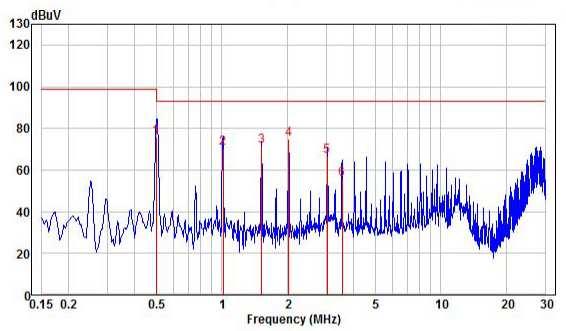
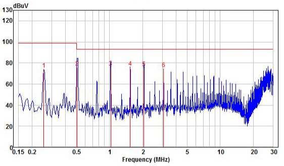
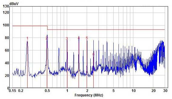
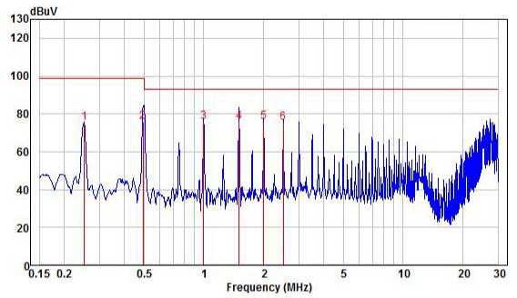
22 Note: C1, C2: PCX uF/275V or equivalent. C3, C4: ALUMINUM CAP or equivalent. C5: VISHAY 293D TANTALUM CHIP CAP. D"<0.8R or equivalent. C6: CHIP CAP or equivalent. CD1, CD2: SEMITEC CURRENT DIODE or equivalent. L1, L2: FERRITE CORE FERROXCUBE T29/19/15-3E6 Φ1.2mm*2/18T or equivalent. ZD1: LITTELFUSE TVS or equivalent. (2) The external filter is required for output conducted noise meet EN50155: EN :2015 MODEL NO C1 C2 L1 CFB600W-110S12 Y1 CAP Y1 CAP CFB600W-110S24 1.0mH 10000pF 10000pF CFB600W-110S28 CFB600W-110S48 Note: Y1 CAP 10000pF Y1 CAP 10000pF 2.2mH L1: 1.0mH FERRITE CORE FERROXCUBE T29/19/15-3E6Φ1.0mm*3/9T or equivalent. 2.2mH FERRITE CORE FERROXCUBE T29/19/15-3E6Φ1.2mm*1/14T or equivalent. 22


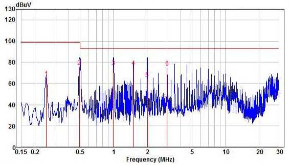
23 Conducted Emission (Input): CFB600W-110S12 Line: Neutral: CFB600W-110S24 Line: Neutral: CFB600W-110S28 Line: Neutral: CFB600W-110S48 Line: Neutral: 23

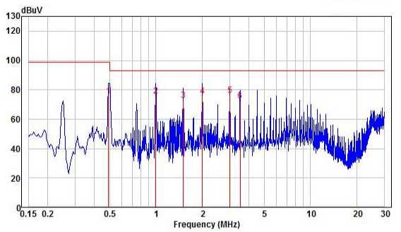
24 Conducted Emission (Output): CFB600W-110S12 Positive: Negative: CFB600W-110S24 Positive: Negative: CFB600W-110S28 Positive: Negative: CFB600W-110S48 Positive: Negative: 24
25 Radiated Emission: CHB600W-110S12 Vertical Horizontal CHB600W-110S24 Vertical Horizontal CHB600W-110S28 Vertical Horizontal CHB600W-110S48 Vertical Horizontal 25
26 7.3 Suggested Configuration for RIA12 Surge Test 26
27 8. Part Number Format: CFB600W II S OO L-Y Parameter Series Nominal Input Voltage Number of Outputs Output Voltage Remote ON/OFF Logic Option Symbol CFB600W II X OO L Y 12: 12 Volts Value CFB600W 110: 110Volts S: Single 24: 24 Volts 28: 28 Volts None: P: Negative Positive C0: Threaded Mounting Holes(M3*0.5) 48: 48 Volts 9. Mechanical Specifications 9.1 Mechanical Outline Diagrams All Dimensions in Inches[mm] Pin Tolerance Inches:x.xx=±0.02, x.xxx=±0.01 ±0.004 Millimeters:x.x=±0.5, x.xx=±0.25 ± [7.64] 0.150[3.81] 0.150[3.81] 0.150[3.81] 0.150[3.81] 0.201[5.10] 0.150[3.81] 0.300[7.62] 0.100[2.54] Mounting Inserts 0.400[10.16] -Vin +Vin - + ON/OFF 0.199[5.05] 0.150[3.81] 4.20[106.7] 0.400[10.16] 0.900[22.86] 1.400[35.56] 2.00[50.8] 2.40[61.0] PIN CONNECTION PIN NUMBER CONNECTION 1 -V Input 2 +V Input 3 -On/Off 4 +On/Off 5~7 +V Output 8~10 -V Output 11 -Sense 12 +Sense 13 TRIM PC IOC AUX 0.50[12.7] 0.22[5.5] 0.050[1.27] 4.60[116.8] Headquarters: CINCON ELECTRONICS CO., LTD. Factory: Cincon North America: 14F, No.306, Sec.4, Hsin Yi Rd. Taipei, Taiwan Tel: Fax: sales@cincon.com.tw Web Site: No. 8-1, Fu Kung Rd. Fu Hsing Industrial Park Fu Hsing Hsiang, Chang Hua Hsien, Taiwan Tel: Fax: Mesa Verde Ave. Ste 180 Ventura, CA Tel: Fax: info@cincon.com 27
ISOLATED DC-DC CONVERTER CFB600 SERIES APPLICATION NOTE
 ISOLATED DC-DC CONVERTER CFB600 SERIES APPLICATION NOTE Approved By: Department Approved By Checked By Written By Enoch Wade Joyce Research and Development Department Danny Jack Benny Quality Assurance
ISOLATED DC-DC CONVERTER CEB75 SERIES APPLICATION NOTE
 ISOLATED DC-DC CONVERTER CEB75 SERIES APPLICATION NOTE Approved By: Department Approved By Checked By Written By Enoch Louis Joyce Research and Development Department Danny Quality Assurance Department
FB SERIES Full-Brick Up to 600 Watt DC-DC Converter
 PRODUCT OVERVIEW The FB series offers up to 600 watts of output power in standard Full-Brick package. This series features high efficiency up to 92%, high power density and 1500 Volts of DC isolation.
ISOLATED DC-DC CONVERTER CHB300W SERIES APPLICATION NOTE
 ISOLATED DC-DC CONVERTER CHB300W SERIES APPLICATION NOTE Approved By: Department Approved By Checked By Written By Enoch Danny Joyce Research and Development Department Jacky Y.D.Yg Benny Quality Assurance
ISOLATED DC-DC CONVERTER CQE50W SERIES APPLICATION NOTE
 ISOLATED DC-DC CONVERTER CQE50W SERIES APPLICATION NOTE Approved By: Department Approved By Checked By Written By Enoch Jacky Joyce Research and Development Department Danny Jack Benny Quality Assurance
ISOLATED DC-DC CONVERTER CHB150W SERIES APPLICATION NOTE
 ISOLATED DC-DC CONVERTER CHB150W SERIES APPLICATION NOTE Approved By: Department Approved By Checked By Written By Enoch Lisa Joyce Research and Development Department Hugo Jack Benny Quality Assurance
ISOLATED DC-DC CONVERTER EC4SBW SERIES APPLICATION NOTE
 ISOLATED DC-DC CONVERTER EC4SBW SERIES APPLICATION NOTE Approved By: Department Approved By Checked By Written By Enoch Danny Eunice Research and Development Department Jacky David Benny Quality Assurance
ISOLATED DC-DC CONVERTER CQB150W-110SXX SERIES APPLICATION NOTE
 ISOLATED DC-DC CONVERTER CQB150W-110SXX SERIES APPLICATION NOTE Approved By: Department Approved By Checked By Written By Enoch Astray Elsie Research and Development Department Jacky David Benny Quality
ISOLATED DC-DC Converter EC2SA SERIES APPLICATION NOTE
 ISOLATED DC-DC Converter EC2SA SERIES APPLICATION NOTE Approved By: Department Approved By Checked By Reported By Enoch Danny Joyce Research and Development Department Jack Benny Quality Assurance Department
ISOLATED DC-DC Converter EC4SAW SERIES APPLICATION NOTE
 ISOLATED DC-DC Converter EC4SAW SERIES APPLICATION NOTE Approved By: Department Approved By Checked By Reported By Enoch Wade Joyce Research and Development Department Danny Jack Benny Quality Assurance
ISOLATED DC-DC CONVERTER CQB50W12 SERIES APPLICATION NOTE
 ISOLATED DC-DC CONVERTER CQB50W12 SERIES APPLICATION NOTE Approved By: Department Approved By Checked By Written By Enoch Danny Wade Research and Development Department Jacky Ryan Benny Quality Assurance
ISOLATED DC-DC CONVERTER CHB300W-110S SERIES APPLICATION NOTE
 ISOLATED DC-DC CONVERTER CHB300W-110S SERIES APPLICATION NOTE Approved By: Department Approved By Checked By Written By Enoch Danny Louis Research and Development Department Jacky Y.D.Yg Benny Quality
ISOLATED DC-DC Converter EC4A-E SERIES APPLICATION NOTE
 ISOLATED DC-DC Converter EC4A-E SERIES APPLICATION NOTE Approved By: Department Approved By Checked By Written By Enoch Eunice Joyce Research and Development Department Danny Jack Benny Quality Assurance
ISOLATED DC-DC Converter EC2SAN SERIES APPLICATION NOTE
 ISOLATED DC-DC Converter EC2SAN SERIES APPLICATION NOTE Approved By: Department Approved By Checked By Reported By Research and Development Enoch Danny Eunice Department Engineering Department (Quality
CBM100S Series Application Note. AC-DC Switching Power Module. CBM100S Series APPLICATION NOTE
 AC-DC Switching Power Module CBM100S Series APPLICATION NOTE Ver. 1.0 Page 1 Content 1.INTRODUCTION...3 2. CBM100S SERIES CONVERTER FEATURES..3 3. TECHNICAL SPECIFICATIONS 4 4. MAIN FEATURES AND FUNCTION.6
AA SERIES (1 x 1 Package) Up to 30 Watt DC-DC Converter
 Up to 30 Watt DC-DC Converter") FEATURES Industry standard footprint (1 inch X 1 inch) Regulated Outputs, Fixed Switching Frequency Up to 90 Efficiency Low No Load Power Consumption Designed for use without tantalum capacitors -40 C
FEATURES Industry standard footprint (1 inch X 1 inch) Regulated Outputs, Fixed Switching Frequency Up to 90 Efficiency Low No Load Power Consumption Designed for use without tantalum capacitors -40 C
ISOLATED DC-DC Converter EC1SAN SERIES APPLICATION NOTE
 ISOLATED DC-DC Converter EC1SAN SERIES APPLICATION NOTE Approved By: Department Approved By Checked By Reported By Enoch Eunice Joyce Research and Development Department Danny Jack Benny Engineering Department
ISOLATED DC-DC Converter EC1TAN SERIES APPLICATION NOTE
 ISOLATED DC-DC Converter EC1TAN SERIES APPLICATION NOTE Approved By: Department Approved By Checked By Reported By Enoch Danny Joyce Research and Development Department Jacky Jack Benny Engineering Department
AA SERIES (1 x 1 Package) Up to 10 Watt DC-DC Converter
 Up to 10 Watt DC-DC Converter") FEATURES Industry standard footprint (1 inch X 1 inch) Regulated Outputs, Fixed Switching Frequency Up to 87 % Efficiency Low No Load Power Consumption Designed for use without tantalum capacitors -40
FEATURES Industry standard footprint (1 inch X 1 inch) Regulated Outputs, Fixed Switching Frequency Up to 87 % Efficiency Low No Load Power Consumption Designed for use without tantalum capacitors -40
PRODUCT OVERVIEW. APPLICATIONS: Distributed Power Architectures Mobile telecommunication Industrial applications Battery operated equipment
 FEATURES Industry Standard 24-Pin DIP package 15Watts Isolated Output 4:1 Input Range Regulated Outputs Up to 90 % Efficiency Low No Load Power Consumption -40 C to +85 C industrial temperature range Negative
AS SERIES (2.00 x 1.6 Package) Up to 20 Watt DC-DC Converter
 Up to 20 Watt DC-DC Converter") PRODUCT OVERVIEW The AS series offer up to 20 watts of output power in standard 2.00 x 1.60 x 0.45 inches packages. This series features high efficiency and 1500 Volts of DC isolation. The AS series provides
PRODUCT OVERVIEW The AS series offer up to 20 watts of output power in standard 2.00 x 1.60 x 0.45 inches packages. This series features high efficiency and 1500 Volts of DC isolation. The AS series provides
Ripple & Max. capacitive Output Current
 0 Watts xxx Series Wide 4: Input Range Single Output Industry Standard /4 Brick -40 C to +0 C Operation 0 VDC Isolation Output Trim ±0% Remote On/Off Year Warranty Dimensions: QSC0:. x.4 x 0. (.9 x. x.
AC-DC Switching ADAPTER TRE25R VI Series APPLICATION NOTE
 AC-DC Switching ADAPTER TRE25R VI Series APPLICATION NOTE Approved By: Department Approved By Checked By Written By Enoch Calvin Jeter Research and Development Department Jack Benny Quality Assurance Department
DC/DC Converter 9 to 36Vdc and 18 to 75Vdc input voltage, 20 Watt Output Power; 3.3 to 15Vdc Single Output and ±12Vdc to ±15Vdc Dual Output
 THN 20WI Series Application Note DC/DC Converter 9 to 36Vdc and 18 to 75Vdc input voltage, 20 Watt Output Power; 3.3 to 15Vdc Single Output and ±12Vdc to ±15Vdc Dual Output Pending Applications Wireless
S24SP series 60W Single Output DC/DC Converter
 Model List Model Number Input Voltage (Range) Output Voltage Output Current Input Current (typ input voltage) Load Regulation Maxcapacitive Load (Cap ESR>=1mohm;Full Efficiency (typ.) load;5%overshoot
AC-DC Switching Power Module CFM61S Series APPLICATION NOTE
 AC-DC Switching Power Module CFM61S Series APPLICATION NOTE Approved By: Department Approved By Checked By Written By Enoch Calvin Jeter Research and Development Department Ovid David Benny Quality Assurance
DC-DC LED DRIVER WITH DALI INTERFACE MODULE ALD SERIES MLD SERIES
 DC-DC LED DRIVER WITH DALI INTERFACE MODULE ALD SERIES MLD SERIES MLD ALD DLD Approved By: Department Approved By Checked By Written By Enoch Tim Paul Research and Development Department Ovid J.D.Yg Benny
S24SE/S24DE series 30W Single/Dual Output DC/DC Converter
 FEATURES Efficiency up to 89% Wide input range, 9V-36V Package with Industry Standard Pinout Package Dimension: 25.4 x25.4 x10.2mm (1.0 x1.0 x0.40 )(No HSK) Over voltage protection, hiccup mode Over current
AC-DC Switching ADAPTER TRH50 VI Series APPLICATION NOTE
 AC-DC Switching ADAPTER TRH50 VI Series APPLICATION NOTE Approved By: Department Approved By Checked By Written By Hunter Ovid Wendong Research and Development Department Jack Benny Quality Assurance Department
FED30-48 S 05 - N HC Series Name Input Output Output Remote Control Assembly Option Voltage Quantity Voltage Option PART NUMBER STRUCTURE
 Automation Datacom IPC Industry Measurement Telecom Automobile Boat Charger Medical PV Railway PART NUMBER STRUCTURE FED30-48 S 05 - N HC Series Name Input Output Output Remote Control Assembly Option
PM24S/DR24S series 60W Single Output DC/DC Converter
 FEATURES Efficiency up to 92% Wide input range, 9V-36V Package Dimension: Panel Mount: 100.0*56.0*19.0mm (3.94 * 2.20 *0.75 ) Din Rail: 118.6*67.1*23.5mm (4.67 *2.64 *0.93 ) Over voltage protection, hiccup
S24SE/S24DE series 15W Single/Dual Output DC/DC Converter
 FEATURES Efficiency up to 89% Wide input range, 9V-36V Package with Industry Standard Pinout Package Dimension: 25.4 x25.4 x10.2mm (1.0 x1.0 x0.40 )(No HSK) Over voltage protection, hiccup mode Over current
Efficiency (typ.) (Range) Load. Output Current Input Current Reflected Ripple
 (Range) Load. Output Current Input Current Reflected Ripple") FEATURES Highest Power Density 1" x 1" x 0.4" Shielded Metal Package Ultra Wide 4:1 Input Range Excellent Efficiency up to % Operating Temp. Range - C to + C Optional Heatsink I/O-isolation Voltage 10VDC
FEATURES Highest Power Density 1" x 1" x 0.4" Shielded Metal Package Ultra Wide 4:1 Input Range Excellent Efficiency up to % Operating Temp. Range - C to + C Optional Heatsink I/O-isolation Voltage 10VDC
FED30-48 S 05 W - N HC Series Name Input Output Output Input Remote Control Assembly Option Voltage Quantity Voltage Range Option
 Automation Datacom IPC Industry Measurement Telecom Automobile Boat Charger Medical PV Railway PART NUMBER STRUCTURE FED30-48 S 05 W - N HC Series Name Input Output Output Input Remote Control Assembly
300W AC-DC Power Supply with PFC CFM300M Series APPLICATION NOTE
 00W AC-DC Power Supply with PFC CFM00M Series APPLICATION NOTE Approved By: Department Approved By Checked By Written By Enoch Wei-Cheng Joyce Research and Development Department Ovid Ryan Benny Quality
S24SE/S24DE series 30W Single/Dual Output DC/DC Converter
 Model List Model Number Input Voltage Output Voltage Output Current Input Current (typ input voltage) (Range) Max. Min. @Max. Load @No Load Load Regulation Maxcapacitive Efficiency Load (typ.) @Max. Load
6. SAFETY 6.1 Input Fusing and Safety Considerations.
 Content 1. INTRODUCTION 2. MODELS 3. CONERTER FEATURES 4. GENERAL DESCRIPTION 4.1 Electrical Description 4.2 Thermal Packaging and Physical Design. 5. MAIN FEATURES AND FUNCTIONS 5.1 Operating Temperature
100W DC-DC Half-Brick Regulated Single Output Converter
 SPECIFICATION MODEL OUTPUT INPUT DC VOLTAGE CURRENT RANGE RATED POWER LINE REGULATION LOAD REGULATION SWITCHING FREQUENCY (Typ.) 500KHz EXTERNAL TRIM ADJ. RANGE (Typ.) RATED DC INPUT VOLTAGE RANGE SURGE
(DOSA) VDC, 5.5 A.
 VDC, 5.5 A.") Features Industry-standard pinout Output: 15 V at 5.5 A, 82.5W max. No minimum load required Low height - 0.374 (9.5mm) max. Basic Insulation Withstands 100 V input transients Fixed-frequency operation
Features Industry-standard pinout Output: 15 V at 5.5 A, 82.5W max. No minimum load required Low height - 0.374 (9.5mm) max. Basic Insulation Withstands 100 V input transients Fixed-frequency operation
(typ.) (Range) Parameter Model Min. Typ. Max. Unit
 (Range) Parameter Model Min. Typ. Max. Unit") FEATURES Smallest Encapsulated 20W! Package Size 1.0 x1.0 x0.4 Ultra-wide 4:1 Input Range Very high Efficiency up to % Operating Temp. Range - C to +85 C Output Voltage Trimmable I/O-isolation Voltage
FEATURES Smallest Encapsulated 20W! Package Size 1.0 x1.0 x0.4 Ultra-wide 4:1 Input Range Very high Efficiency up to % Operating Temp. Range - C to +85 C Output Voltage Trimmable I/O-isolation Voltage
Cool Power Technologies
 Cool Power Technologies Sixteenth-Brick Isolated DC/DC Converter Features Industry-standard pinout Wide input voltage range: 36 75Vin Output: 3.3 V at 12 A, 40W max. No minimum load required Low height
LDM60S SERIES AC-DC LED DRIVER Application Note LDM60S. LED Power Supply Application Note
 LDM60S LED Power Supply Page 1 Content Revision History 3 1. INTRODUCTION 4 2. LDM60S LED DRIVER FEATURES 4 3. GENERAL DESCRIPTION 4 4. TECHNICAL SPECIFICATIONS 5 5. MAIN FEATURES AND FUNCTIONS 7 5.1 Operating
S24SP05012 series 60W Single Output DC/DC Converter
 Model List Model Number S24SP05012 Input Voltage (Range) Output Voltage Output Current Input Current (typ input voltage) Load Regulation Maxcapacitive Load (Cap ESR>=10mohm;Full Efficiency load;5%overshoot
OVP 2:1. Wide Range. Protection
 10W, Wide Input Range DIP, Single & Dual Output DC/DC s Key Features High Efficiency up to 88 10 Isolation MTBF > 1,000,000 Hours 2:1 Wide Input Range CSA9-1 Safety Approval Complies with EN522 Class A
S24SP12004 series 40W Single Output DC/DC Converter
 FEATURES Efficiency up to 92.8% Wide input range, 9V-36V Package with Industry Standard Pinout Package Dimension: Without heat sink 5.8 x25.4 x1.5mm (2. x1. x.41 ) With heat sink 5.8 x25.4 x17.5mm (2.
S24SP24003 series 60W Single Output DC/DC Converter
 FEATURES Efficiency up to 93% Wide input range, 9V-36V Package with Industry Standard Pinout Package Dimension: Without heat sink 5.8 x25.4 x1.5mm (2. x1. x.41 ) With heat sink 5.8 x25.4 x17.5mm (2. x1.
S15 SERIES SIP or SMT. NON-ISOLATED DC-DC Converter. S15 SIP / SMT SERIES Vin, Vout, 15A. APPLICATION NOTES Ver 1.0
 NON-ISOLATED DC-DC Converter S15 SIP / SMT SERIES 3.0-5.5Vin, 0.9-3.63Vout, 15A APPLICATION NOTES Ver 1.0 S15-5S3.3T (Through-Hole) Converter S15-5S3.3 SMT Version Converter Page 1 1. INTRODUCTION 3 2.
MIW3000 Series EMI. 5-6W, Wide Input Range DIP, Single & Dual Output DC/DC Converters MINMAX. Block Diagram. Key Features
 -6W, Wide Input Range DIP, Single & DC/DC s Key Features Efficiency up to 10 Isolation MTBF > 1,000,000 Hours 2:1 Wide Input Range UL19 Safety Approval Complies with EN22 Class A Temperature Performance
VFB400W - QXX - SXXX
 date 01/30/2014 page 1 of 10 SERIES: VFB400W DESCRIPTION: DC-DC CONVERTER FETURES 400 W isolated output industry standard full brick package 4:1 input range (9~36, 18~75 ) single regulated outputs from
LDM100S SERIES AC-DC LED DRIVER Application Note LDM100S. LED Power Supply Application Note
 LDM100S LED Power Supply Page 1 Content Revision History 2 1. INTRODUCTION 3 2. LDM100S LED DRIVER FEATURES 3 3. GENERAL DESCRIPTION 3 4. TECHNICAL SPECIFICATIONS 4 5. MAIN FEATURES AND FUNCTIONS 6 5.1
PXD30-xxWS-xx-Single Output DC/DC Converters
 PXD30-xxWS-xx-Single Output DC/DC Converters 9 to 36 Vdc and 18 to 75 Vdc input, 1.5 to 15 Vdc Single Output, 30W Applications Wireless Network Telecom / Datacom Industry Control System Measurement Semiconductor
ATA 8W Series. Product Descriptions. 8 Watts DC/DC Converter
 8 Watts DC/DC Converter Page 1 Total Power: 8 Watts Input Voltage: 9 to 36Vdc 18 to 75Vdc # of Outputs: Single, dual Special Features Smallest Encapsulated 8W Converter Industrial Standard DIP16 Package
PM24S/PM24D series 30W Single/Dual Output DC/DC Converter
 FEATURES Efficiency up to 88% Wide input range, 9V-36V Package Dimension: Panel Mount: 100.0*56.0*19.0mm (3.94 * 2.20 *0.75 ) Din Rail: 118.6*67.1*23.5mm (4.67 *2.64 *0.93 ) Over voltage protection, hiccup
ESB Series Embedded EMC Filter Up to 40W converter
 Features High Ffficiency up to 91% 2:1 / 4:1 Ultra-Wide input range Compact size 1.6 x 1.0 x 0.4 & 1.6 x 1.0 x 0.5 Standard DOSA pin out; Fully replaceable with 2 x1 standard case Metal Case Six-Sided
H80SV12017 * * FEATURES. Delphi Series H80SV, half Brick Family DC/DC Power Modules: 16.8~137.5 Vin, 54/48/24/15/12Vout,200W APPLICATIONS
 H80SV12017 200W DC/DC Power Modules Delphi Series H80SV, half Brick Family DC/DC Power Modules: 16.8~137.5 Vin, 54/48/24/15/12Vout,200W The H80SV series Half-Brick is isolated 200W DC/DC converters with
Distributing Tomorrow s Technologies For Today s Designs Toll-Free:
 2W, Wide Input Range DIP, Single & DC/DC s Key Features Efficiency up to 81 Isolation MTBF > 1,000,000 Hours 2:1 Wide Input Range CSA1 Safety Approval Low Ripple and Noise Short Circuit Protection Complies
 http://www.mmtmachrone.com 96D SERIES FEATURES: 30W DIL PACKAGE Recognized By UL 60950-1 2:1 WIDE INPUT RANGE 100% BURNED IN HIGH EFFICIENCY UL 94V-0 PACKAGE MATERIAL CUSTOMIZED SOLUTIONS AVAILABLE RoHS
Distributing Tomorrow s Technologies For Today s Designs Toll-Free:
 3W, Wide Input Range DIP, Single & DC/DC s Key Features Efficiency up to 82 Isolation MTBF > 1,000,000 Hours 2:1 Wide Input Range Low Cost Complies with EN022 Class A Temperature Performance -2 to +71
9 to 36 Vdc and 18 to 75 Vdc input, 3.3 to 15 Vdc Single Output, 40W. Features
 PXF40xxWSxx Single Output DC/DC Converter 9 to 36 Vdc and 18 to 75 Vdc input, 3.3 to 15 Vdc Single Output, 40W Features Single output current up to 10A 40 watts maximum output power 4:1 ultra wide input
SPS20 Series small size isolated DC/DC converters
 SPS20 Series small size isolated DC/DC converters Features High Efficiency Wide operating temperature range ( -20 C to +71 C ) Wide 2:1 input range Built in over current protection circuit Input Output
Parameter Symbol Min Typ Max Unit Operating voltage Range Vin Vdc Input current at 36V. Iin - - A Input current at 55V
 QPC20A NonIoslated Quater Brick Buck Converters Features Industry standard Quarterbrick 58.42mm x 36.83mm x 13mm (2.3in x 1.45in x 0.512in) High efficiency Single output Constant switching frequency Synchronous
SPS20 Series small size isolated DC/DC converters
 18 36Vdc Input, Maximum Power: 20W FEB 10, 2011 SPS20 Series small size isolated DC/DC converters Features High Efficiency Wide operating temperature range ( -20 C to +71 C ) Wide 2:1 input range Built
Efficiency (typ.) (Range) Load VDC VDC ma ma(typ.) ma(typ.) μf % MCWI05-12S
 (Range) Load VDC VDC ma ma(typ.) ma(typ.) μf % MCWI05-12S") FEATURES Smallest Encapsulated 5W Ultracompact SIP8 Package Ultrawide 4 : 1 Input Voltage Range Fully Regulated Output Voltage I/O Isolation 1500 VDC Operating Ambient Temp. Range40 to 75 No Min. Requirement
FEATURES Smallest Encapsulated 5W Ultracompact SIP8 Package Ultrawide 4 : 1 Input Voltage Range Fully Regulated Output Voltage I/O Isolation 1500 VDC Operating Ambient Temp. Range40 to 75 No Min. Requirement
WAF S 12 W - N S DR Series Name Input Output Output Input Remote Control Load Share Assembly Voltage Quantity Voltage Range Option Option Option
 Railway Automation Datacom IPC Industry Measurement Telecom Charger Automobile Boat Medical PV PART NUMBER STRUCTURE WAF300-48 S 12 W - N S DR Series Name Input Output Output Input Remote Control Load
 http://www.mmtmachrone.com 93D SERIES FEATURES: 60W DIL PACKAGE INDUSTRY STANDARD PACKAGE 2:1 WIDE INPUT RANGE 100% BURNED IN HIGH EFFICIENCY UL94V-0 PACKAGE MATERIAL CUSTOM SOLUTIONS AVAILABLE RoHS COMPLIANT
Cool Power Technologies
 - 1 - Cool Power Technologies Eighth-Brick Isolated DC/DC Converter Features Ultra-wide input voltage range: 18 75Vin Output: 5V at 15A, 75W max. High Efficiency 92% Typical @ FL ROHS II Directive 2011/65/EU
Output Voltage Output Amps Input Range Max. Iin FL Efficiency (Tb=25 C) O/P Set Point
 O/P Set Point") Miniature 4.59 x 2.4 x 0.5. Size High Power Density up to 90.78W/ Inch ³ High Efficiency up to 90.5% at 230VAC (28V) Low Output Noise Metal Baseplate Thermal Protection Over Voltage Protection Current
Miniature 4.59 x 2.4 x 0.5. Size High Power Density up to 90.78W/ Inch ³ High Efficiency up to 90.5% at 230VAC (28V) Low Output Noise Metal Baseplate Thermal Protection Over Voltage Protection Current
PXD10-Single Output DC/DC Converter
 PXD10-Single Output DC/DC Converter 9 to 18 Vdc, 18 to 36 Vdc and 36 to 75 Vdc input, 3.3 to 15 Vdc Single Output, 10W Features Single output current up to 2A 10 watts maximum output power 2:1 wide input
Cool Power Technologies
 - 1 - Cool Power Technologies Eighth-Brick Isolated DC/DC Converter Features Ultra-wide input voltage range: 18 72Vin Output: 12V at 9A,108W max. High Efficiency 92% Typical @ FL ROHS II Directive 2011/65/EU
Series AM50E-NZ 50 Watt DC-DC Converter
 FEATURES: Wide Input range 2:1 Input to Output Isolation of 1500 High Efficiency up to 93% Input Over Voltage and Under Voltage Lockout Remote On/Off Control Output OVP, OCP & SCP Trim Adjustment Operating
Series AM30EW-Z 30 Watt DC-DC Converter
 FEATURES: Click on Series name for product info on aimtec.com Models Single output Model Input Voltage Ultra Wide :1 input range Remote on/off control Efficiency up to 91% Input/ Isolation 100VDC Soft
Efficiency (typ.) (Range) Max. Load VDC VDC ma ma ma(typ.) ma(typ.) μf % MJWI10-24S033
 (Range) Max. Load VDC VDC ma ma ma(typ.) ma(typ.) μf % MJWI10-24S033") FEATURES Package Size 1.0 x1.0 x0.4 Ultrawide 4:1 Input Range High Efficiency up to 87% Operating Temp. Range 40 C to 80 C I/Oisolation Voltage 1500VDC Remote On/Off Control Input Filter complies to EN55022,Class
FEATURES Package Size 1.0 x1.0 x0.4 Ultrawide 4:1 Input Range High Efficiency up to 87% Operating Temp. Range 40 C to 80 C I/Oisolation Voltage 1500VDC Remote On/Off Control Input Filter complies to EN55022,Class
Notes: Note1: Max. capacitive load is tested at nominal input voltage and full load. Single or Dual
 Features Regulated Converters Description 6-Side Shielding External ON/OFF control 1.6kV Isolation UL/CSA/EN-695-1 Certified 2:1 Input Voltage Range Continuous Short Circuit Protection Efficiency up to
Cool Power Technologies
 - 1 - Cool Power Technologies Eighth-Brick Isolated DC/DC Converter Features Ultra-wide input voltage range: 9 36Vin Output: 12V at 6 A, 72W max. ROHS Directive 2002/95/EC Compliant No minimum load required
Note1: Measured at nominal input voltage and full load Note2: Measured at minimum input voltage and constant resistive load
 Features Regulated Converters Description :1 wide input voltage range 1.kV isolation UL certified Efficiency up to 88% Fixed operating frequency Six-Sided continuous shield No minimum load required The
360 WATT MTW SERIES DC/DC CONVERTERS
 Description The 4:1 Input Voltage 360 Watt Single MTW DC/DC converter provides a precisely regulated dc output. The output voltage is fully isolated from the input, allowing the output to be positive or
HRS50 Series 50W isolated DC/DC converters
 HRS50 Series 50W isolated DC/DC converters Features High Efficiency Wide operating temperature range ( -40 C to +85 C ) Wide 2:1 input range Standard half brick size Six side shield Input Output Isolated
Content. 8. MECHANICAL OUTLINE DIAGRAMS LDP40 Mechanical Outline Diagrams LDP40 Wire Color Description 10
 Application Note V12 MAY 2014 Content 1. INTRODUCTION 3 2. LDP40 SERIES LED DRIVER FEATURES 3 3. GENERAL DESCRIPTION 3 4. TECHNICAL SPECIFICATIONS 4 5. MAIN FEATURES AND FUNCTIONS 6 5.1 Operating Temperature
Cool Power Technologies
 - 1 - Cool Power Technologies Eighth-Brick Isolated DC/DC Converter Features Ultra-wide input voltage range: 40 150Vin Output: 24V @ 1.2A ROHS Directive 2011/65/EU Compliant No minimum load required Low
MI2000ERW. Series. Miniature 1 x 1 20W, Ultra-Wide 2:1 Input DC/DC Con vert ers. Key Features:
 MI2000ERW Miniature 1 x 1 20W, Ultra-Wide 2:1 Input DC/DC Con vert ers Key Features: 20W Output Power 2:1 Input Voltage Range Miniature 1 x 1 Case 1,500 VDC Isolation Meets CISPR 32/EN 55032 High Efficiency
Q54SJ W DC/DC Power Modules FEATURES. Q54SJ12058, 700W Quarter Brick DC/DC Power Modules: 40~60Vin, 12.2V/ 57.4A out OPTIONS APPLICATIONS
 Q54SJ12058 700W DC/DC Power Modules FEATURES High efficiency: 96.4% @ 12.2V/57.4A out size : 57.9 x 36.8 x 12.0mm (2.28 x1.45 x0.47 ) (open frame) 57.9 x 36.8 x 13.4mm (2.28 x1.45 x0.53 ) (with base plate)
Cool Power Technologies
 - 1 - Cool Power Technologies Sixteenth-Brick Isolated DC/DC Converter Features Industry-standard pinout Ultra-wide input voltage range: 18 72Vin Output: 5 V at 14 A, 70W max. High Efficiency 90% typical
DC/DC Converter URA_LD-20WR3 & URB_LD-20WR3 Series
 20W isolated DC-DC converter with Ultra-wide input and Regulated Dual / Single Output FEATURES Ultra-wide 4:1 input voltage range High efficiency up to 90% No-load power consumption as low as 0.15W I/O
500 WATT MXW SERIES DC/DC CONVERTERS
 4:1 Input voltage range High power density Small size 2.4 x 2.5 x 0.52 Efficiency up to 95.7% Excellent thermal performance with metal case Over-Current and Short Circuit Protection Over-Temperature protection
DSA150 Series. xxx Series. 150 Watts. AC-DC Power Supplies. Models & Ratings. Mechanical Details 3.92 (99.8) 2.18 (55.5) 4.92 (125.
 2.18 (55.5) 4.92 (125.") 15 Watts xxx Series Ultra Slim Design 15% Peak Load for 3 seconds Ambient Operation from -1 C to +7 C High Efficiency Selectable Overload Characteristic Selectable Remote Inhibit or Enable 3 Year Warranty
15 Watts xxx Series Ultra Slim Design 15% Peak Load for 3 seconds Ambient Operation from -1 C to +7 C High Efficiency Selectable Overload Characteristic Selectable Remote Inhibit or Enable 3 Year Warranty
STB Series 2:1 & 4:1 Vin range / up to 60W 1/16 Brick
 2:1 & 4:1 Vin range / up to W 1/16 Brick Features Industry-Standard DOSA pin out 4:1 / 2:1 Ultra-Wide input range High Ffficiency 91%@ 5V (SR topology) Compact size 1.49 x 1.46 x.5 Metal Case Six-Sided
Delphi Series H48SC3R325, 85W Half Brick Family DC/DC Power Modules: 48V in, 3.3V/25A out
 FEATURES High efficiency: 93% @ 3.3V/25A Standard footprint: 61.0x57.9x10.0mm (2.40 2.28 0.39 ) Industry standard pin out Fixed frequency operation Input UVLO, Output OCP, OVP, OTP Basic insulation 2250V
Cool Power Technologies
 - 1 - Cool Power Technologies Eighth-Brick Isolated DC/DC Converter Features Ultra-wide input voltage range: 9 36Vin Output: 12V at 8A, 96W max. High Efficiency 92% Typical @ FL ROHS II Directive 2011/65/EU
MLSR100 Series. High Efficiency, 1.0A Surface Mount, POL Switching Regulators. Key Features:
 MLSR100 Series High Efficiency, 1.0A Surface Mount, POL Switching Regulators Electrical Specifications Specifi cations typical @ +25 C, nominal input voltage & rated output current, unless otherwise noted.
Volant NCF010 Series. Non-Isolated 10A SIP DC/DC Converters
 Features: Small size, minimal footprint/low profile A Output Current (all voltages) High Efficiency: up to 95% High reliability RoHS Compliant Cost efficient open frame design Pre-bias monotonic start-up
Series AMSRL1-78JZ Up to 12 Watt DC-DC Switching Regulator
 Click on Series name for product info on aimtec.com FEATURES: Picture Coming Soon Models Single output Model Input Voltage (V) Switching Regulator SMD Package Low Quiescent Current Efficiency Up To 95%
Content. 8. MECHANICAL OUTLINE DIAGRAMS LDP60 Mechanical Outline Diagrams LDP60 Wire Color Description 10
 Content 1. INTRODUCTION 3 2. LDP60 SERIES LED DRIVER FEATURES 3 3. GENERAL DESCRIPTION 3 4. TECHNICAL SPECIFICATIONS 4 5. MAIN FEATURES AND FUNCTIONS 6 5.1 Operating Temperature Range 6 5.2 Over Temperature
QAE100W SERIES QUARTER-BRICK DC-DC CONVERTER
 SERIES QUARTER-BRICK DC-DC CONVERTER 4:1 ULTRA WIDE INPUT RANGE UP TO 90Watts FEATURES NO MINIMUM LOAD REQUIRED LOW STANDBY POWER CONSUMPTION SOFT-START 2250 INPUT TO OUTPUT BASIC INSULATION SAFETY MEETS
DC/DC Converter URF1D_QB-75W Series
 75W, wide input voltage, isolated & regulated single output DC-DC converter Patent Protection RoHS FEATURES Wide input voltage range: 66-16 High efficiency up to 91% Low no-load power consumption Isolation
Cool Power Technologies
 Cool Power Technologies Sixteenth-Brick Isolated DC/DC Converter Features Industry-standard pinout Ultra-wide input voltage range: 18 75Vin Output: 5 V at 8 A, 40W max. High Efficiency 90% typical @FL
150 WATT QSW DC/DC CONVERTERS
 Description The 4:1 Input Voltage 150 Watt Single QSW DC/DC converter provides a precisely regulated dc output. The output voltage is fully isolated from the input, allowing the output to be positive or
Output Input Efficiency PARD (mvp-p) Vin Nom. (V)
 Vin Nom. (V)") Features: Small size, minimal footprint SMT/SIP package 5A Output Current (all voltages) High Efficiency: up to 94% High reliability RoHS Compliant Cost efficient open frame design Output voltage programmable
Features: Small size, minimal footprint SMT/SIP package 5A Output Current (all voltages) High Efficiency: up to 94% High reliability RoHS Compliant Cost efficient open frame design Output voltage programmable
Cool Power Technologies
 - 1 - Cool Power Technologies Eighth-Brick Isolated DC/DC Converter Features Wide input voltage range: 36 72Vin Output: 29.8V at 4.7A, 140 W max. High Efficiency 93% Typical @ FL ROHS II Directive 2011/65/EU
TBD. Delphi E36SR Series DC/DC Power Modules: 18~60 in, 12V/4A out, 48W FEATURES OPTIONS APPLICATIONS
 FEATURES High efficiency: 91% @ 12V/4A Size: 58.4x22.8x8.73mm (2.30 x0.90 x0.34 ) Standard footprint Industry standard pin out TBD Fixed frequency operation Input UVLO, Output OCP, OVP, OTP 1500V isolation
MAX. OUTPUT POWER 24/48/72/96/110 VDC 5 VDC 6 A 30 W 82% 0RQB-30Y05L. 0 R QB - 30 Y 05 L y. Output Power. Input Range
 The 0RQB-30Y05L is an isolated DC/DC converter providing 30 W of output power from a wide input range (24 V, 48 V, 72 V, 96 V, 110 V typical). Standard features include remote on/off, input under-voltage