ISOLATED DC-DC CONVERTER CFB600 SERIES APPLICATION NOTE
|
|
|
- Madeleine Glenn
- 5 years ago
- Views:
Transcription

1 ISOLATED DC-DC CONVERTER CFB600 SERIES APPLICATION NOTE Approved By: Department Approved By Checked By Written By Enoch Wade Joyce Research and Development Department Danny Jack Benny Quality Assurance Department 1
2 Contents 1. Introduction DC-DC Converter Features Electrical Block Diagram Technical Specifications Main Features and Functions Operating Temperature Range Output Voltage Adjustment Over Current Protection Output Over Voltage Protection Remote On/Off UVLO&OVLO (Under/Over Voltage Lock Out) Over Temperature Protection Applications Recommended Layout, PCB Footprint and Soldering Information Convection Requirements for Cooling Thermal Considerations Power De-rating Full Brick Heat Sinks: Efficiency VS Test Set-Up Output Voltage Adjustment Output Remote Sensing Output Ripple and Noise Output Capacitance Parallel Operation IOC signal Auxiliary Power for output signal On/Off Control Safety & EMC Input Fusing and Safety Considerations EMC Considerations Part Number Mechanical Specifications Mechanical Outline Diagrams
3 1. Introduction This specification describes the features and functions of Cincon s CFB600 series of isolated DC-DC Converters. These are highly efficient, reliable and compact, high power density, single output DC/DC converters. The modules can be used in the field of telecommunications, data communications, wireless communications, servers, base station, etc. The CFB600 series can deliver up to 50A output current and provide a precisely regulated output voltage over a wide range of and 36-75VDC. The modules can achieve high efficiency up to 92%. The module offers direct cooling of dissipative components for excellent thermal performance. Standard features include isolated remote on/off (positive or negative), remote sense, output voltage adjustment, over voltage, over current and over temperature protection. Parallel operation is also optional. 2. DC-DC Converter Features W Isolated Output Efficiency (at full load) up to 92% Regulated Output Fixed Switching Frequency Input Under/Over Voltage Lockout Protection Over Current Protection Isolated remote On/Off Continuous Short Circuit Protection Industry Standard Full-Brick Package Fully Isolated to 1500VDC 3. Electrical Block Diagram +VIN (2) +VOUT (5,6,7) +SENSE (12) -VOUT -VIN (1) (4) +ON/OFF UVLO/OVLO CIRCUIT PWM CONTROLLER AUX CIRCUIT OTPO ISOLATION OVP CIRCUIT AUX (16) IOC (15) PC/NC (14) (8,9,10) -SENSE (11) -ON/OFF (3) ON/OFF CIRCUIT OTP CIRCUIT OCP CIRCUIT Electrical Block Diagram for CFB600 series Modules REFERENCE & ERROR AMP (13) TRIM 3
4 4. Technical Specifications (All specifications are typical at nominal input, full load at 25 C unless otherwise noted.) ABSOLUTE MAXIMUM RATINGS Stresses in excess of the absolute maximum ratings can cause permanent damage to the device. These are absolute stress ratings only, functional operation of the device is not implied at these or any other conditions in excess of those given in the operations sections of the data sheet. Exposure to absolute maximum ratings for extended periods can adversely affect the device reliability. PARAMETER NOTES and CONDITIONS Device Min. Typical Max. Units Input Voltage Continuous Operating Case Temperature 24SXX SXX V dc C Storage Temperature C Input/Output Isolation Voltage INPUT CHARACTERISTICS 1 minute 1500 V dc PARAMETER NOTES and CONDITIONS Device Min. Typical Max. Units Operating Input Voltage Input Under Voltage Lockout Turn-On Voltage Threshold Turn-Off Voltage Threshold Lockout Hysteresis Voltage Input Over Voltage Lockout Turn-On Voltage Threshold Turn-Off Voltage Threshold Lockout Hysteresis Voltage Maximum Input Current No- Input Current 24SXX SXX SXX SXX SXX SXX SXX SXX SXX SXX SXX SXX SXX SXX %, V in=18v 24SXX %, V in=36v 48SXX S S S S S S S S S S V dc V dc V dc V dc V dc V dc V dc A ma 4
5 PARAMETER NOTES and CONDITIONS Device Min. Typical Max. Units Inrush Current (I 2 t) 1.0 A 2 s OUTPUT CHARACTERISTICS PARAMETER NOTES and CONDITIONS Device Min. Typical Max. Units Output Voltage Set Point Output Voltage Regulation V in=nominal V in, I o = I o_max, Tc=25 C 5 Vo=12V Vo=24V Vo=28V Vo=32V Vo=48V Regulation I o=i o_min to I o_max ±0.5 % Line Regulation V in=low line to high line ±0.2 % Temperature Coefficient T C=-40 C to 100 C ±0.03 %/ C Output Voltage Ripple and Noise Peak-to-Peak RMS Operating Output Current Range Output DC Current Limit Inception Power Good Signal(IOG) Output Capacitance 20MHz bandwidth, Full load, 10uF tantalum and 1.0uF ceramic capacitors (48V: 10uF aluminum and 1.0uF ceramic capacitors) 20MHz bandwidth, Full load, 10uF tantalum and 1.0uF ceramic capacitors (48V: 10uF aluminum and 1.0uF ceramic capacitors) Vo=12V 120 Vo=24V 240 Vo=28V 280 Vo=32V 320 Vo=48V 480 Vo=12V 60 Vo=24V 100 Vo=28V 100 Vo=32V 120 Vo=48V S S Vo=12V 0 50 Vo=24V 0 25 Vo=32V 0 19 Vo=48V Output Voltage=90% Nominal Output Voltage % Vout ready: low level, sink current All 20 ma Vout not ready: open drain output, applied voltage All 50 V Full load (resistive) DYNAMIC CHARACTERISTICS 12V ~48V PARAMETER NOTES and CONDITIONS Device Min. Typical Max. Units Output Voltage Current Transient Step Change in Output Current Setting Time (within 1% Vout nominal) Turn-On Delay and Rise Time Turn-On Delay Time, From On/Off Control Turn-On Delay Time, From Input d i/d t=0.1a/us, change from 75% to 100% to 75% of Io,max V dc mv mv All ±3 ±5 % d i/d t=0.1a/us All 500 us V on/off to 10%V o_set All 75 ms V in_ min to 10%V o_set All 250 ms A uf
6 PARAMETER NOTES and CONDITIONS Device Min. Typical Max. Units Output Voltage Rise Time 10%V o_set to 90% Vo_set All 50 ms EFFICIENCY PARAMETER NOTES and CONDITIONS Device Min. Typical Max. Units 100% ISOLATION CHARACTERISTICS 24S S S S S S S S S S48 92 % PARAMETER NOTES and CONDITIONS Device Min. Typical Max. Units Isolation Voltage 1 minute; input/output, input/case, output/case input/remote, output/remote 1500 V dc Isolation Resistance 10 MΩ Isolation Capacitance 4000 pf FEATURE CHARACTERISTICS PARAMETER NOTES and CONDITIONS Device Min. Typical Max. Units Switching Frequency ON/OFF Control Negative Remote On/Off logic 48S12 48S28 48S Others 250 Logic Low (Module Off) ma Logic High (Module On) ma ON/OFF Control Positive Remote On/Off logic Logic High (Module Off) ma Logic High (Module On) ma Auxiliary Output Voltage All V Auxiliary Output Current All 20 ma Share Accuracy (50% % 100% load) Off Converter Input Current Shutdown input idle current 50 ma Output Voltage Trim Range P out=max rated power % Output Over Voltage Protection KHz % Over-Temperature Shutdown 110 C GENERAL SPECIFICATIONS PARAMETER NOTES and CONDITIONS Device Min. Typical Max. Units MTBF I o=100% of I o_max: T a=25 C per MIL-HDBK-217F 450 Weight 220 grams K hours 6
7 5. Main Features and Functions 5.1 Operating Temperature Range The CFB600 series converters can be operated within a wide case temperature range of -40 C to 100 C. Consideration must be given to the de-rating curves when ascertaining maximum power that can be drawn from the converter. The maximum power drawn from full brick models is influenced by usual factors, such as: Input voltage range Output load current Forced air or natural convection 5.2 Output Voltage Adjustment Section 6.8 describes in detail how to trim the output voltage with respect to its set point. The output voltage on all models is adjustable within the range of 60% to 110%. 5.3 Over Current Protection The converter is protected against over current or short circuit conditions. At the instance of current-limit inception, the module enters a constant current mode of operation. While the fault condition exists, the module will remain in this constant current mode, and can remain in this mode until the fault is cleared. The unit operates normally once the output current is reduced back into its specified range. 5.4 Output Over Voltage Protection The converter is protected against output over voltage conditions. When the output voltage is higher than the specified range, the module enters a hiccup mode of operation. 5.5 Remote On/Off The On/Off input pins permit the user to turn the power module on or off via a system signal from the primary side or the secondary side. Two remote on/off options are available. Negative logic turns the module on as long as a current (1-10mA) is flowing between +on/off and on/off and inactive when no current is flowing. Positive logic turns the module off as long as a current (1-10mA) is flowing between +on/off and on/off and active when no current is flowing. 5.6 UVLO&OVLO (Under/Over Voltage Lock Out) Input under/over voltage lockout is standard with this converter. At input voltages below/beyond the input under voltage lockout limit, the module operation is disabled. 5.7 Over Temperature Protection These modules have an over temperature protection circuit to safeguard against thermal damage. When the case temperature rises above over temperature shutdown threshold, the converter will shut down to protect it from overheating. The module will automatically restart after it cools down. 6. Applications 6.1 Recommended Layout, PCB Footprint and Soldering Information The system designer or end user must ensure that metal and other components in the vicinity of the converter meet the spacing requirements for which the system is approved. Low resistance and inductance PCB layout traces are the norm and should be used where possible. Due consideration must also be given to proper low impedance tracks between power module, input and output grounds. The recommended soldering profile and PCB layout are shown below. Temperature ( C) Lead Free Wave Soldering Profile Time (Seconds) Note: 1. Soldering Materials: Sn/Cu/Ni 2. Ramp up rate during preheat: 1.4 /Sec ( From 50 to 100 ) 3. Soaking temperature: 0.5 /Sec ( From 100 to 130 ), 60±20 seconds 4. Peak temperature: 260, above 250 3~6 Seconds 5. Ramp up rate during cooling: /Sec ( From 260 to 150 ) 7
8 TOP VIEW 2.4mm PLATED THROUGH HOLE 4.8mm PAD SIZE 3.5mm NON THROUGH HOLE 1.4mm PLATED THROUGH HOLE 2.8mm PAD SIZE Recommend PCB Pad layout 6.2 Convection Requirements for Cooling To predict the approximate cooling needed for the full brick module, refer to the power de-rating curves in section 6.4. These de-rating curves are approximations of the ambient temperatures and airflows required to keep the power module temperature below its maximum rating. Once the module is assembled in the actual system, the module s temperature should be monitored to ensure it does not exceed 100 C as being measured at the center of the top of the case (thus verifying proper cooling). 6.3 Thermal Considerations The power module operates in a variety of thermal environments; however, sufficient cooling should be provided to help ensure reliable operation of the unit. Heat is removed by conduction, convection, and radiation to the surrounding environment. The test data is presented in section 6.4. The power output of the module should not be allowed to exceed rated power (V o_set x I o_max ). 8
9 6.4 Power De-rating The operating case temperature range of CFB600 series is -40 to When operating the CFB600 series, proper de-rating or cooling is needed. The maximum case temperature under any operating condition should not be exceeded 100. The following curve is the de-rating curve of CFB600 series without heat sink. Power Disspated,Pd(Watts) Example: Power Dissipated vs Ambient Temperature and Air Flow Ambient Temperature,Ta(Deg. C) What is the minimum airflow necessary for a CFB600-48S12 operating at nominal line, an output current of 30A, and a maximum ambient temperature of 40 Solution: Given: V in =48V dc, V o =12V dc, Io=30A Determine Power dissipation (P d ): Pd =Pi-Po=Po(1-η)/η Pd =12 30 (1-0.9)/0.9=40Watts Determine airflow: Given: P d =40W and Ta=40 Check above Power de-rating curve: minimum airflow= 700 ft./min. Verifying: The maximum temperature rise Where: T = Pd Rca= =54 The maximum case temperature Tc=Ta+ T= 94 <100 The R ca is thermal resistance from case to ambience. The Ta is ambient temperature and the Tc is case temperature. Chart of Thermal Resistance vs Air Flow AIR FLOW RATE Natural Convection 20 ft./min. (0.1 m/s) 100 ft./m in. (0.5 m /s) 200 ft./m in. (1.0 m /s) 300 ft./m in. (1.5 m /s) 400 ft./m in. (2.0 m /s) 500 ft./m in. (2.5 m /s) 600 ft./m in. (3.0 m /s) 700 ft./m in. (3.5 m /s) 800 ft./m in. (4.0 m /s) TYPICAL R ca Natural Convection 20ft./min. (0.1m/s) 3.82 /W 100 ft./min. (0.5m/s) 3.23 /W 200 ft./min. (1.0m/s) 2.71 /W 300 ft./min. (1.5m/s) 2.28 /W 400 ft./min. (2.0m/s) 1.92 /W 500 ft./min. (2.5m/s) 1.68 /W 600 ft./min. (3.0m/s) 1.50 /W 700 ft./min. (3.5m/s) 1.35 /W 800 ft./min. (4.0m/s) 1.23 /W 9
10 The following curve is the de-rating curve of CFB600 series with heat sink M-B Power Dissipat ed vs Am bie nt Temperatu re with h eat sink M-B01 2 Power Disspated,Pd(Watts) Natu ral C onvectio n 20 ft./m in. (0.1 m/s) 10 0 ft. /min. (0. 5 m /s) 20 0 ft. /min. (1. 0 m /s) 30 0 ft. /min. (1. 5 m /s) 40 0 ft. /min. (2. 0 m /s) 0 Example: Ambient Tem perature,ta(deg. C) Forced Convection Power De-rating with Heat Sink M-B012 What is the minimum airflow necessary for a CFB600-48S12 operating at nominal line, an output current of 50A, and a maximum ambient temperature of 40 Solution: Given: V in =48V dc, Vo=12V dc, Io=50A Determine Power dissipation (P d ): Pd=Pi-Po=Po(1-η)/η Pd=12x50x(1-0.9)/0.9=66.7Watts (Chart of Thermal Resistance vs Air Flow) Determine airflow: Given: Pd=66.7W and Ta=40 Check above Power de-rating curve: minimum airflow= 400 ft./min. Verifying: Where: The maximum temperature rise T = Pd Rca= =55.4 The maximum case temperature Tc=Ta+ T= 95.4 <100 The Rca is thermal resistance from case to ambience. The Ta is ambient temperature and the Tc is case temperature. AIR FLOW RATE TYPICAL R ca Natural Convection 20ft./min. (0.1m/s) 2.4 /W 100 ft./min. (0.5m/s) 1.76 /W 200 ft./min. (1.0m/s) 1.17 /W 300 ft./min. (1.5m/s) 1.00 /W 400 ft./min. (2.0m/s) 0.83 /W 10
11 6.5 Full Brick Heat Sinks: All Dimension In mm Heat-sink M-B012 Longitudinal Fins ± R ± R R0.4 4-R R Heat Sink (Clear Mounting Inserts Φ3.3mm Through): 116.8*61*25.4(M-B012) (G ) Thermal PAD: SR60*115.8*0.23 (G ) Screw: M3*20L (G75A ) Nut: NH+WOM3*P0.5N(G75A ) Heat-sink M-C997 All Dimension In mm Longitudinal Fins ± ± R R ± ± R0.4 4-R0.2 C0.3 C M3*0.5 Heat Sink (Mounting Inserts M3*0.5 Through): 116.8*61*25.4(M-C997) (G ) Thermal PAD: SR60*115.8*0.23 (G ) Screw: M3*20L (G75A ) Washer: WS3.2N (G75A47A0752) R0.8 AIR FLOW RATE TYPICAL R ca Natural Convection 20ft./min. (0.1m/s) 2.4 /W 100 ft./min. (0.5m/s) 1.76 /W 200 ft./min. (1.0m/s) 1.17 /W 300 ft./min. (1.5m/s) 1.00 /W 400 ft./min. (2.0m/s) 0.83 /W 11
12 Full Brick Heat Sink Assembly Screw Heatsink Thermal Pad Screw nut Heat Sink: M-B012 Thermal PAD: SR60*115.8*0.23 (G ) Screw: M3*20L (G75A ) Nut: NH+WOM3*P0.5N(G75A ) Heatsink Thermal Pad Washer Screw Heat Sink: M-C997 Thermal PAD: SR60*115.8*0.23 (G ) Screw: M3*20L (G75A ) Washer: WS3.2N (G75A47A0752) 12
13 6.6 Efficiency VS. 95% C FB600-24S12 E fficiency VS. 95% C FB600-48S12 E fficiency VS. 90% 90% 85% 85% E fficiency 80% 75% 18V in E fficiency 80% 75% 36V in 70% 24V in 70% 48V in 65% 36V in 65% 75V in 60% 10% 20% 30% 40% 50% 60% 70% 80% 90% 100% 60% 10% 20% 30% 40% 50% 60% 70% 80% 90% 100% 95% CFB600-24S24 Efficiency VS. 95% CFB600-48S24 Efficiency VS. 90% 90% 85% 85% Efficiency 80% 75% 70% 65% 18Vin 24Vin 36Vin Efficiency 80% 75% 70% 65% 36Vin 48Vin 75Vin 60% 10% 20% 30% 40% 50% 60% 70% 80% 90% 100% 60% 10% 20% 30% 40% 50% 60% 70% 80% 90% 100% 95% C FB600-24S28 E fficiency VS. 95% CFB700-48S28 Efficiency VS. 90% 90% 85% 85% E fficiency 80% 75% 18V in Efficiency 80% 75% 36Vin 70% 24V in 70% 48Vin 65% 36V in 65% 75Vin 60% 10% 20% 30% 40% 50% 60% 70% 80% 90% 100% 60% 10% 20% 30% 40% 50% 60% 70% 80% 90% 100% 13
14 95% C FB600-24S32 E fficiency VS. 95% C FB600-48S32 E fficiency VS. 90% 90% 85% 85% E fficiency 80% 75% 18V in E fficiency 80% 75% 36V in 70% 24V in 70% 48V in 65% 36V in 65% 75V in 60% 10% 20% 30% 40% 50% 60% 70% 80% 90% 100% 60% 10% 20% 30% 40% 50% 60% 70% 80% 90% 100% 95% CFB600-24S48 Efficiency VS. 95% CFB600-48S48 Efficiency VS. 90% 90% 85% 85% Efficiency 80% 75% 70% 65% 18Vin 24Vin 36Vin Efficiency 80% 75% 70% 65% 36Vin 48Vin 75Vin 60% 10% 20% 30% 40% 50% 60% 70% 80% 90% 100% 60% 10% 20% 30% 40% 50% 60% 70% 80% 90% 100% 14
15 6.7 Test Set-Up The basic test set-up to measure parameters such as efficiency and load regulation is shown below. When testing the modules under any transient conditions please ensure that the transient response of the source is sufficient to power the equipment under test. we can calculate: Efficiency regulation and line regulation. The value of efficiency is defined as: Vo Io η = 100% Vin Iin Where: V o is output voltage, I o is output current, V in is input voltage, I in is input current. The value of load regulation is defined as: VFL VNL. reg = 100% VNL Where: V FL is the output voltage at full load V NL is the output voltage at no load The value of line regulation is defined as: VHL VLL Line. reg = 100% VLL Where: V HL is the output voltage of maximum input voltage at full load. V LL is the output voltage of minimum input voltage at full load. 6.8 Output Voltage Adjustment The Trim input permits the user to adjust the output voltage up or down according to the trim range specification (60% to 110% of nominal output). This is accomplished by connecting an external resistor between the +Vout and +Sense pin for trim up and between the TRIM and Sense pin for trim down, see Figure Output voltage trim circuit configuration The Trim pin should be left open if trimming is not being used. The output voltage can be determined by the following equations: Vf Vout Rt ( ) Rt + 33 = Rt Rt + 33 = ( Vo + VR) Vf Unit: KΩ Vo: Nominal Output Voltage Recommend Rt=6.8KΩ The output voltage can also be adjustment by using external DC voltage CFB600 Series Test Setup Recommend C1and C2 Value C1:220uF/100V, C2:470uF/100V For CFB600 series it s necessary to connect the input electrolytic capacitor C1 with low ESR to prevent the effective of input line inductance to the DC/DC converter. For stable operation, connect a low impedance electrolytic capacitor C2 in the output terminals. When operated at lower temperature than -20, increasing the C2 capacitance with three or four times more than the recommended value. Output Voltage = TRIM Terminal Voltage * Nominal Output Voltage 15
16 6.9 Output Remote Sensing The CFB600 SERIES converter has the capability to remotely sense both lines of its output. This feature moves the effective output voltage regulation point from the output of the unit to the point of connection of the remote sense pins. This feature automatically adjusts the real output voltage of the CFB600 series in order to compensate for voltage drops in distribution and maintain a regulated voltage at the point of load. The remote-sense voltage range is: [(+V out ) - (-V out )] [(+Sense) (-Sense)] 10% of V o_nominal If the remote sense feature is not to be used, the sense pins should be connected locally. The +Sense pin should be connected to the +Vout pin at the module and the -Sense pin should be connected to the -Vout pin at the module. This is shown in the schematic below. emphasizes low resistance and inductance tracks in consideration of high current applications. Output capacitors with their associated ESR values have an impact on loop stability and bandwidth. The minimum output capacitance is 470uF which need three or four times capacitance when operating below -20 and the absolute maximum value of CFB600 series output capacitance is 10000uF.For values larger than this, please contact your local CINCON s representative Parallel Operation The CFB600 series are also designed for parallel operation. When paralleled, the load current can be equally shared between the modules by connecting the PC pins together. There are two different parallel operations for CFB600 series, one is parallel operation when load can t be supplied by only one power unit; the other is the N+1 redundant operation which is high reliable for load of N units by using N+1 units. (a) parallel operation +S +V Note: Although the output voltage can be increased by both the remote sense and by the trim, the maximum increase for the output voltage is not the sum of both. The maximum increase is the larger of either the remote sense or the trim. The amount of power delivered by the module is defined as the voltage at the output terminals multiplied by the output current. When using remote sense and trim, the output voltage of the module can be increased and consequently increase the power output of the module if output current remains unchanged. Care should be taken to ensure that the maximum output power of the module remains at or below the maximum rated power (Maximum rated power = V o,set x I o,max ) 6.10 Output Ripple and Noise -V -S PC +S +V -V -S PC (b) Parallel operation with programmed and adjustable output L O A D +Vin +Vout DC C1 R1 +ON/OFF -ON/OFF CFB600 Series +SNS TRIM -SNS C2 1uF 10uF BNC to scope -Vin -Vout Output ripple and noise is measured with 1.0uF ceramic and 10uF solid tantalum capacitors across the output Output Capacitance The CFB600 series converters provide unconditional stability with or without external capacitors. For good transient response, low ESR output capacitors should be located close to the point of load. PCB design 16


 Controlling the ON/OFF terminal from the output side, Recommend R2 value is 5.1k (0.1W). 6.")

17 (c) N+1 redundant connection (d) N+1 redundant connection with programmed output and adjustable output voltage This signal is LOW when the converter is normally operating and HIGH when the converter is disabled or when the converter is abnormally operating Auxiliary Power for output signal The auxiliary power supply output is within 7-13V with maximum current of 20 ma. Ground reference is the sense Pin On/Off Control The converter s On/Off can be controlled from the input side or the output side. Output voltage turns on when current is made to through On/Off terminals which can be reached by opening or closing the switches. The maximum current through the On/Off pin is 10mA, setting the resistor value to avoid the maximum current through the On/Off pins. (A) Controlling the On/Off terminal from the input side, recommend R1 value is 30K (0.5W) for 48Vin and 15K (0.25W) for 24Vin. (B) Controlling the ON/OFF terminal from the output side, Recommend R2 value is 5.1k (0.1W) IOG signal Normal and abnormal operation of the converter can be monitored by using the I.O.G signal. Output of this signal monitor is located at the secondary side and is open collector output, you can use the signal by the internal aux power supply or the the external DC supply as the following figures. the ground reference is the Sense. By internal AUX By external DC supply 17
18 7. Safety & EMC 7.1 Input Fusing and Safety Considerations The CFB600 series converters have no internal fuse. In order to achieve maximum safety and system protection, always use an input line fuse. We recommended a 60A time delay fuse for 24V in models, and 30A for 48V in models. It is recommended that the circuit have a transient voltage suppressor diode (TVS) across the input terminal to protect the unit against surge or spike voltage and input reverse voltage (as shown). FUSE +Vin +Vo + Vin - TVS R- -Vin -Vo 7.2 EMC Considerations Suggested Circuits for Conducted EMI CLASS A (1) EMI and conducted noise meet EN55022 Class A specifications: Model No. C1 C2 C3 CY1/CY2 CY3/CY4 C4 L1 L2 R1 CFB600-24S uF/50V 2.2uF/100V 1000uF/50V 0.1uF NC 470uF/100V+10uF/50V Short 1mH 15K CFB600-24S uF/50V 2.2uF/100V 1000uF/50V 0.1uF NC 470uF/100V+10uF/50V Short 1mH 15K CFB600-24S uF/50V 2.2uF/100V 1000uF/50V 0.1uF NC 470uF/100V+10uF/50V Short 1mH 15K CFB600-24S uF/50V 2.2uF/100V 1000uF/50V 0.1uF NC 470uF/100V+10uF/50V Short 1mH 15K CFB600-24S uF/50V 2.2uF/100V 1000uF/50V 0.1uF NC 470uF/100V+10uF/50V Short 1mH 15K CFB600-48S12 NC 470uF/100V 470uF/100V 10000pF 10000pF*2 470uF/100V Short 2mH 30K CFB600-48S24 NC 470uF/100V 470uF/100V 10000pF 10000pF*2 470uF/100V Short 2mH 30K CFB700-48S28 NC 470uF/100V 470uF/100V 10000pF 10000pF*2 470uF/100V Short 2mH 30K CFB600-48S32 NC 470uF/100V 470uF/100V 10000pF 10000pF*2 470uF/100V Short 2mH 30K CFB600-48S48 NC 470uF/100V 470uF/100V 10000pF 10000pF*2 470uF/100V Short 2mH 30K Note: 1000uF/50V is NIPPON CHEMI-CON KY series aluminum capacitors, 470uF/100V is Nichicon PS(M) series aluminum capacitors,cy1, CY2, CY3 & CY4 is Y1 capacitors, other capacitors is ceramic capacitors 2220 size. Inductor core material is VAC W523, 1mH is 1.2mm*2 6T, 2mH is 1.5mm*1 8T. I 18


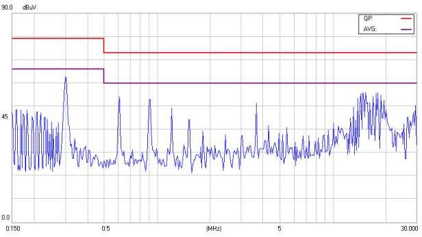

19 Conducted Class A of CFB600-24S12 Conducted Class A of CFB600-24S24 Conducted Class A of CFB600-24S28 Conducted Class A of CFB600-24S32 Conducted Class A of CFB600-24S48 Conducted Class A of CFB600-48S12 Conducted Class A of CFB600-48S24 Conducted Class A of CFB700-48S28 Conducted Class A of CFB600-48S32 Conducted Class A of CFB600-48S48 19
20 8. Part Number Format: CFB600 II X OO L Parameter Series Nominal Input Voltage Number of Outputs Output Voltage Remote ON/OFF Logic Symbol CFB600 II X OO L 12: 12 Volts Value CFB600 CFB700 24: 24 Volts 48: 48 Volts 9. Mechanical Specifications 9.1 Mechanical Outline Diagrams All Dimensions In Inches(mm) Pin DIA Tolerances Inches:.XX±0.02.XXX±0.010 ±0.004 Millimeters:.X±0.5.XX±0.25 ±0.1 S: Single 24: 24 Volts 28: 28 Volts 32: 32 Volts 48: 48 Volts None: P: Negative Positive 4.099(104.11) 3.949(100.30) 3.799(96.49) 3.649(92.68) 3.499(88.87) 3.349(85.06) (1.00) (2.00) PIN CONNECTIONS 1.701(43.20) 1.301(33.04) (35.56) 2.00(50.8) 2.251(57.17) 2.40(61.0) PIN NUMBER FUNCTION -Vin +Vin -ON/OFF +ON/OFF +Vo -Vo 0.901(22.88) 0.751(19.07) 0.020(5.05) Mounting Through 3.5mm 4Pl. 4.20(106.7) 0.400(10.16) 0.900(22.86) 0.501(12.72) 0.02(5.1) S +S TRIM PC/NC IOG 16 AUX 0.22(5.5) 0.50(12.7) 4.60(116.8) CFB600 Mechanical Outline Diagram CINCON ELECTRONICS CO., LTD. Headquarters: 14F, No.306, Sec.4, Hsin Yi Rd. Taipei, Taiwan Tel: Fax: sales@cincon.com.tw Web Site: Factory: No. 8-1, Fu Kung Rd. Fu Hsing Industrial Park Fu Hsing Hsiang, Chang Hua Hsien, Taiwan Tel: Fax: Cincon North America: 1655 Mesa Verde Ave. Ste 180 Ventura, CA Tel: Fax: info@cincon.com 20
FB SERIES Full-Brick Up to 600 Watt DC-DC Converter
 PRODUCT OVERVIEW The FB series offers up to 600 watts of output power in standard Full-Brick package. This series features high efficiency up to 92%, high power density and 1500 Volts of DC isolation.
ISOLATED DC-DC CONVERTER CEB75 SERIES APPLICATION NOTE
 ISOLATED DC-DC CONVERTER CEB75 SERIES APPLICATION NOTE Approved By: Department Approved By Checked By Written By Enoch Louis Joyce Research and Development Department Danny Quality Assurance Department
ISOLATED DC-DC CONVERTER CHB300W SERIES APPLICATION NOTE
 ISOLATED DC-DC CONVERTER CHB300W SERIES APPLICATION NOTE Approved By: Department Approved By Checked By Written By Enoch Danny Joyce Research and Development Department Jacky Y.D.Yg Benny Quality Assurance
ISOLATED DC-DC CONVERTER CHB150W SERIES APPLICATION NOTE
 ISOLATED DC-DC CONVERTER CHB150W SERIES APPLICATION NOTE Approved By: Department Approved By Checked By Written By Enoch Lisa Joyce Research and Development Department Hugo Jack Benny Quality Assurance
ISOLATED DC-DC CONVERTER CQE50W SERIES APPLICATION NOTE
 ISOLATED DC-DC CONVERTER CQE50W SERIES APPLICATION NOTE Approved By: Department Approved By Checked By Written By Enoch Jacky Joyce Research and Development Department Danny Jack Benny Quality Assurance
ISOLATED DC-DC Converter EC4SAW SERIES APPLICATION NOTE
 ISOLATED DC-DC Converter EC4SAW SERIES APPLICATION NOTE Approved By: Department Approved By Checked By Reported By Enoch Wade Joyce Research and Development Department Danny Jack Benny Quality Assurance
ISOLATED DC-DC Converter EC2SA SERIES APPLICATION NOTE
 ISOLATED DC-DC Converter EC2SA SERIES APPLICATION NOTE Approved By: Department Approved By Checked By Reported By Enoch Danny Joyce Research and Development Department Jack Benny Quality Assurance Department
ISOLATED DC-DC CONVERTER CFB600W-110S SERIES APPLICATION NOTE
 ISOLATED DC-DC CONVERTER CFB600W-110S SERIES APPLICATION NOTE Approved By: Department Approved By Checked By Written By Enoch Hugo Sam Research and Development Department Jacky Ryan Benny Quality Assurance
ISOLATED DC-DC Converter EC2SAN SERIES APPLICATION NOTE
 ISOLATED DC-DC Converter EC2SAN SERIES APPLICATION NOTE Approved By: Department Approved By Checked By Reported By Research and Development Enoch Danny Eunice Department Engineering Department (Quality
ISOLATED DC-DC Converter EC4A-E SERIES APPLICATION NOTE
 ISOLATED DC-DC Converter EC4A-E SERIES APPLICATION NOTE Approved By: Department Approved By Checked By Written By Enoch Eunice Joyce Research and Development Department Danny Jack Benny Quality Assurance
ISOLATED DC-DC Converter EC1TAN SERIES APPLICATION NOTE
 ISOLATED DC-DC Converter EC1TAN SERIES APPLICATION NOTE Approved By: Department Approved By Checked By Reported By Enoch Danny Joyce Research and Development Department Jacky Jack Benny Engineering Department
CBM100S Series Application Note. AC-DC Switching Power Module. CBM100S Series APPLICATION NOTE
 AC-DC Switching Power Module CBM100S Series APPLICATION NOTE Ver. 1.0 Page 1 Content 1.INTRODUCTION...3 2. CBM100S SERIES CONVERTER FEATURES..3 3. TECHNICAL SPECIFICATIONS 4 4. MAIN FEATURES AND FUNCTION.6
ISOLATED DC-DC CONVERTER EC4SBW SERIES APPLICATION NOTE
 ISOLATED DC-DC CONVERTER EC4SBW SERIES APPLICATION NOTE Approved By: Department Approved By Checked By Written By Enoch Danny Eunice Research and Development Department Jacky David Benny Quality Assurance
ISOLATED DC-DC Converter EC1SAN SERIES APPLICATION NOTE
 ISOLATED DC-DC Converter EC1SAN SERIES APPLICATION NOTE Approved By: Department Approved By Checked By Reported By Enoch Eunice Joyce Research and Development Department Danny Jack Benny Engineering Department
AA SERIES (1 x 1 Package) Up to 30 Watt DC-DC Converter
 Up to 30 Watt DC-DC Converter") FEATURES Industry standard footprint (1 inch X 1 inch) Regulated Outputs, Fixed Switching Frequency Up to 90 Efficiency Low No Load Power Consumption Designed for use without tantalum capacitors -40 C
FEATURES Industry standard footprint (1 inch X 1 inch) Regulated Outputs, Fixed Switching Frequency Up to 90 Efficiency Low No Load Power Consumption Designed for use without tantalum capacitors -40 C
AA SERIES (1 x 1 Package) Up to 10 Watt DC-DC Converter
 Up to 10 Watt DC-DC Converter") FEATURES Industry standard footprint (1 inch X 1 inch) Regulated Outputs, Fixed Switching Frequency Up to 87 % Efficiency Low No Load Power Consumption Designed for use without tantalum capacitors -40
FEATURES Industry standard footprint (1 inch X 1 inch) Regulated Outputs, Fixed Switching Frequency Up to 87 % Efficiency Low No Load Power Consumption Designed for use without tantalum capacitors -40
ISOLATED DC-DC CONVERTER CQB150W-110SXX SERIES APPLICATION NOTE
 ISOLATED DC-DC CONVERTER CQB150W-110SXX SERIES APPLICATION NOTE Approved By: Department Approved By Checked By Written By Enoch Astray Elsie Research and Development Department Jacky David Benny Quality
PRODUCT OVERVIEW. APPLICATIONS: Distributed Power Architectures Mobile telecommunication Industrial applications Battery operated equipment
 FEATURES Industry Standard 24-Pin DIP package 15Watts Isolated Output 4:1 Input Range Regulated Outputs Up to 90 % Efficiency Low No Load Power Consumption -40 C to +85 C industrial temperature range Negative
AS SERIES (2.00 x 1.6 Package) Up to 20 Watt DC-DC Converter
 Up to 20 Watt DC-DC Converter") PRODUCT OVERVIEW The AS series offer up to 20 watts of output power in standard 2.00 x 1.60 x 0.45 inches packages. This series features high efficiency and 1500 Volts of DC isolation. The AS series provides
PRODUCT OVERVIEW The AS series offer up to 20 watts of output power in standard 2.00 x 1.60 x 0.45 inches packages. This series features high efficiency and 1500 Volts of DC isolation. The AS series provides
ISOLATED DC-DC CONVERTER CQB50W12 SERIES APPLICATION NOTE
 ISOLATED DC-DC CONVERTER CQB50W12 SERIES APPLICATION NOTE Approved By: Department Approved By Checked By Written By Enoch Danny Wade Research and Development Department Jacky Ryan Benny Quality Assurance
AC-DC Switching ADAPTER TRE25R VI Series APPLICATION NOTE
 AC-DC Switching ADAPTER TRE25R VI Series APPLICATION NOTE Approved By: Department Approved By Checked By Written By Enoch Calvin Jeter Research and Development Department Jack Benny Quality Assurance Department
Ripple & Max. capacitive Output Current
 0 Watts xxx Series Wide 4: Input Range Single Output Industry Standard /4 Brick -40 C to +0 C Operation 0 VDC Isolation Output Trim ±0% Remote On/Off Year Warranty Dimensions: QSC0:. x.4 x 0. (.9 x. x.
AC-DC Switching ADAPTER TRH50 VI Series APPLICATION NOTE
 AC-DC Switching ADAPTER TRH50 VI Series APPLICATION NOTE Approved By: Department Approved By Checked By Written By Hunter Ovid Wendong Research and Development Department Jack Benny Quality Assurance Department
ISOLATED DC-DC CONVERTER CHB300W-110S SERIES APPLICATION NOTE
 ISOLATED DC-DC CONVERTER CHB300W-110S SERIES APPLICATION NOTE Approved By: Department Approved By Checked By Written By Enoch Danny Louis Research and Development Department Jacky Y.D.Yg Benny Quality
DC-DC LED DRIVER WITH DALI INTERFACE MODULE ALD SERIES MLD SERIES
 DC-DC LED DRIVER WITH DALI INTERFACE MODULE ALD SERIES MLD SERIES MLD ALD DLD Approved By: Department Approved By Checked By Written By Enoch Tim Paul Research and Development Department Ovid J.D.Yg Benny
DC/DC Converter 9 to 36Vdc and 18 to 75Vdc input voltage, 20 Watt Output Power; 3.3 to 15Vdc Single Output and ±12Vdc to ±15Vdc Dual Output
 THN 20WI Series Application Note DC/DC Converter 9 to 36Vdc and 18 to 75Vdc input voltage, 20 Watt Output Power; 3.3 to 15Vdc Single Output and ±12Vdc to ±15Vdc Dual Output Pending Applications Wireless
PXD30-xxWS-xx-Single Output DC/DC Converters
 PXD30-xxWS-xx-Single Output DC/DC Converters 9 to 36 Vdc and 18 to 75 Vdc input, 1.5 to 15 Vdc Single Output, 30W Applications Wireless Network Telecom / Datacom Industry Control System Measurement Semiconductor
LDM60S SERIES AC-DC LED DRIVER Application Note LDM60S. LED Power Supply Application Note
 LDM60S LED Power Supply Page 1 Content Revision History 3 1. INTRODUCTION 4 2. LDM60S LED DRIVER FEATURES 4 3. GENERAL DESCRIPTION 4 4. TECHNICAL SPECIFICATIONS 5 5. MAIN FEATURES AND FUNCTIONS 7 5.1 Operating
AC-DC Switching Power Module CFM61S Series APPLICATION NOTE
 AC-DC Switching Power Module CFM61S Series APPLICATION NOTE Approved By: Department Approved By Checked By Written By Enoch Calvin Jeter Research and Development Department Ovid David Benny Quality Assurance
6. SAFETY 6.1 Input Fusing and Safety Considerations.
 Content 1. INTRODUCTION 2. MODELS 3. CONERTER FEATURES 4. GENERAL DESCRIPTION 4.1 Electrical Description 4.2 Thermal Packaging and Physical Design. 5. MAIN FEATURES AND FUNCTIONS 5.1 Operating Temperature
300W AC-DC Power Supply with PFC CFM300M Series APPLICATION NOTE
 00W AC-DC Power Supply with PFC CFM00M Series APPLICATION NOTE Approved By: Department Approved By Checked By Written By Enoch Wei-Cheng Joyce Research and Development Department Ovid Ryan Benny Quality
S15 SERIES SIP or SMT. NON-ISOLATED DC-DC Converter. S15 SIP / SMT SERIES Vin, Vout, 15A. APPLICATION NOTES Ver 1.0
 NON-ISOLATED DC-DC Converter S15 SIP / SMT SERIES 3.0-5.5Vin, 0.9-3.63Vout, 15A APPLICATION NOTES Ver 1.0 S15-5S3.3T (Through-Hole) Converter S15-5S3.3 SMT Version Converter Page 1 1. INTRODUCTION 3 2.
LDM100S SERIES AC-DC LED DRIVER Application Note LDM100S. LED Power Supply Application Note
 LDM100S LED Power Supply Page 1 Content Revision History 2 1. INTRODUCTION 3 2. LDM100S LED DRIVER FEATURES 3 3. GENERAL DESCRIPTION 3 4. TECHNICAL SPECIFICATIONS 4 5. MAIN FEATURES AND FUNCTIONS 6 5.1
S24SE/S24DE series 30W Single/Dual Output DC/DC Converter
 FEATURES Efficiency up to 89% Wide input range, 9V-36V Package with Industry Standard Pinout Package Dimension: 25.4 x25.4 x10.2mm (1.0 x1.0 x0.40 )(No HSK) Over voltage protection, hiccup mode Over current
VFB400W - QXX - SXXX
 date 01/30/2014 page 1 of 10 SERIES: VFB400W DESCRIPTION: DC-DC CONVERTER FETURES 400 W isolated output industry standard full brick package 4:1 input range (9~36, 18~75 ) single regulated outputs from
PXD10-Single Output DC/DC Converter
 PXD10-Single Output DC/DC Converter 9 to 18 Vdc, 18 to 36 Vdc and 36 to 75 Vdc input, 3.3 to 15 Vdc Single Output, 10W Features Single output current up to 2A 10 watts maximum output power 2:1 wide input
9 to 36 Vdc and 18 to 75 Vdc input, 3.3 to 15 Vdc Single Output, 40W. Features
 PXF40xxWSxx Single Output DC/DC Converter 9 to 36 Vdc and 18 to 75 Vdc input, 3.3 to 15 Vdc Single Output, 40W Features Single output current up to 10A 40 watts maximum output power 4:1 ultra wide input
S24SE/S24DE series 15W Single/Dual Output DC/DC Converter
 FEATURES Efficiency up to 89% Wide input range, 9V-36V Package with Industry Standard Pinout Package Dimension: 25.4 x25.4 x10.2mm (1.0 x1.0 x0.40 )(No HSK) Over voltage protection, hiccup mode Over current
Efficiency (typ.) (Range) Load. Output Current Input Current Reflected Ripple
 (Range) Load. Output Current Input Current Reflected Ripple") FEATURES Highest Power Density 1" x 1" x 0.4" Shielded Metal Package Ultra Wide 4:1 Input Range Excellent Efficiency up to % Operating Temp. Range - C to + C Optional Heatsink I/O-isolation Voltage 10VDC
FEATURES Highest Power Density 1" x 1" x 0.4" Shielded Metal Package Ultra Wide 4:1 Input Range Excellent Efficiency up to % Operating Temp. Range - C to + C Optional Heatsink I/O-isolation Voltage 10VDC
S24SE/S24DE series 30W Single/Dual Output DC/DC Converter
 Model List Model Number Input Voltage Output Voltage Output Current Input Current (typ input voltage) (Range) Max. Min. @Max. Load @No Load Load Regulation Maxcapacitive Efficiency Load (typ.) @Max. Load
S24SP series 60W Single Output DC/DC Converter
 Model List Model Number Input Voltage (Range) Output Voltage Output Current Input Current (typ input voltage) Load Regulation Maxcapacitive Load (Cap ESR>=1mohm;Full Efficiency (typ.) load;5%overshoot
100W DC-DC Half-Brick Regulated Single Output Converter
 SPECIFICATION MODEL OUTPUT INPUT DC VOLTAGE CURRENT RANGE RATED POWER LINE REGULATION LOAD REGULATION SWITCHING FREQUENCY (Typ.) 500KHz EXTERNAL TRIM ADJ. RANGE (Typ.) RATED DC INPUT VOLTAGE RANGE SURGE
OVP 2:1. Wide Range. Protection
 10W, Wide Input Range DIP, Single & Dual Output DC/DC s Key Features High Efficiency up to 88 10 Isolation MTBF > 1,000,000 Hours 2:1 Wide Input Range CSA9-1 Safety Approval Complies with EN522 Class A
Content. 8. MECHANICAL OUTLINE DIAGRAMS LDP40 Mechanical Outline Diagrams LDP40 Wire Color Description 10
 Application Note V12 MAY 2014 Content 1. INTRODUCTION 3 2. LDP40 SERIES LED DRIVER FEATURES 3 3. GENERAL DESCRIPTION 3 4. TECHNICAL SPECIFICATIONS 4 5. MAIN FEATURES AND FUNCTIONS 6 5.1 Operating Temperature
(typ.) (Range) Parameter Model Min. Typ. Max. Unit
 (Range) Parameter Model Min. Typ. Max. Unit") FEATURES Smallest Encapsulated 20W! Package Size 1.0 x1.0 x0.4 Ultra-wide 4:1 Input Range Very high Efficiency up to % Operating Temp. Range - C to +85 C Output Voltage Trimmable I/O-isolation Voltage
FEATURES Smallest Encapsulated 20W! Package Size 1.0 x1.0 x0.4 Ultra-wide 4:1 Input Range Very high Efficiency up to % Operating Temp. Range - C to +85 C Output Voltage Trimmable I/O-isolation Voltage
Delphi Series H48SC3R325, 85W Half Brick Family DC/DC Power Modules: 48V in, 3.3V/25A out
 FEATURES High efficiency: 93% @ 3.3V/25A Standard footprint: 61.0x57.9x10.0mm (2.40 2.28 0.39 ) Industry standard pin out Fixed frequency operation Input UVLO, Output OCP, OVP, OTP Basic insulation 2250V
Q54SJ W DC/DC Power Modules FEATURES. Q54SJ12058, 700W Quarter Brick DC/DC Power Modules: 40~60Vin, 12.2V/ 57.4A out OPTIONS APPLICATIONS
 Q54SJ12058 700W DC/DC Power Modules FEATURES High efficiency: 96.4% @ 12.2V/57.4A out size : 57.9 x 36.8 x 12.0mm (2.28 x1.45 x0.47 ) (open frame) 57.9 x 36.8 x 13.4mm (2.28 x1.45 x0.53 ) (with base plate)
H80SV12017 * * FEATURES. Delphi Series H80SV, half Brick Family DC/DC Power Modules: 16.8~137.5 Vin, 54/48/24/15/12Vout,200W APPLICATIONS
 H80SV12017 200W DC/DC Power Modules Delphi Series H80SV, half Brick Family DC/DC Power Modules: 16.8~137.5 Vin, 54/48/24/15/12Vout,200W The H80SV series Half-Brick is isolated 200W DC/DC converters with
Content. 8. MECHANICAL OUTLINE DIAGRAMS LDP60 Mechanical Outline Diagrams LDP60 Wire Color Description 10
 Content 1. INTRODUCTION 3 2. LDP60 SERIES LED DRIVER FEATURES 3 3. GENERAL DESCRIPTION 3 4. TECHNICAL SPECIFICATIONS 4 5. MAIN FEATURES AND FUNCTIONS 6 5.1 Operating Temperature Range 6 5.2 Over Temperature
Delphi Series S36SA, 25W Family DC/DC Power Modules: 18Vin to 60Vin, 3.3V/8A out
 FEATURES High efficiency: 88.5% @ 3.3V/8A Size: 47.20mmx29.5mmx8.15mm (1.86 x1.16 x0.32 ) Wide input voltage range: 18V~60V Standard footprint Surface mountable Industry standard pin out Fixed frequency
MIW3000 Series EMI. 5-6W, Wide Input Range DIP, Single & Dual Output DC/DC Converters MINMAX. Block Diagram. Key Features
 -6W, Wide Input Range DIP, Single & DC/DC s Key Features Efficiency up to 10 Isolation MTBF > 1,000,000 Hours 2:1 Wide Input Range UL19 Safety Approval Complies with EN22 Class A Temperature Performance
Delphi Series V48SR, 1/16 th Brick 66W
 FEATURES High efficiency: 90.5% @ 15V/4.4A Size: 33.0 x 22.9 x 9.5 mm (1.30 x0.90 x0.37 ) Industry standard footprint and pinout Fixed frequency operation SMD and through-hole versions Input UVLO and OVP
PM24S/DR24S series 60W Single Output DC/DC Converter
 FEATURES Efficiency up to 92% Wide input range, 9V-36V Package Dimension: Panel Mount: 100.0*56.0*19.0mm (3.94 * 2.20 *0.75 ) Din Rail: 118.6*67.1*23.5mm (4.67 *2.64 *0.93 ) Over voltage protection, hiccup
Distributing Tomorrow s Technologies For Today s Designs Toll-Free:
 2W, Wide Input Range DIP, Single & DC/DC s Key Features Efficiency up to 81 Isolation MTBF > 1,000,000 Hours 2:1 Wide Input Range CSA1 Safety Approval Low Ripple and Noise Short Circuit Protection Complies
V36SE12005 FEATURES. Delphi Series V36SE, 1/16 th. Brick DC/DC Power Modules: 18~75Vin, up to 60W OPTIONS APPLICATIONS
 FEATURES V36SE12005 High efficiency: 88% @ 12V/5A, 48Vin Size: 33.0x22.8x8.7mm (1.30 x0.90 x0.34 ) Industry standard 1/16th brick size & pinout Input UVLO OTP and output OCP, OVP (default is auto-recovery)
Output Voltage Output Amps Input Range Max. Iin FL Efficiency (Tb=25 C) O/P Set Point
 O/P Set Point") Miniature 4.59 x 2.4 x 0.5. Size High Power Density up to 90.78W/ Inch ³ High Efficiency up to 90.5% at 230VAC (28V) Low Output Noise Metal Baseplate Thermal Protection Over Voltage Protection Current
Miniature 4.59 x 2.4 x 0.5. Size High Power Density up to 90.78W/ Inch ³ High Efficiency up to 90.5% at 230VAC (28V) Low Output Noise Metal Baseplate Thermal Protection Over Voltage Protection Current
TBD. Delphi E36SR Series DC/DC Power Modules: 18~60 in, 12V/4A out, 48W FEATURES OPTIONS APPLICATIONS
 FEATURES High efficiency: 91% @ 12V/4A Size: 58.4x22.8x8.73mm (2.30 x0.90 x0.34 ) Standard footprint Industry standard pin out TBD Fixed frequency operation Input UVLO, Output OCP, OVP, OTP 1500V isolation
Delphi Series V36SE, 1/16 th Brick DC/DC Power Modules: 18~75Vin, up to 50W
 FEATURES High efficiency: 91%@5V/10A,48Vin 90%@5V/8A,24Vin Size: 33.0x22.8x9.3mm (1.30 x0.90 x0.37 ) Industry standard 1/16th brick size & pinout Input UVLO OTP and output OCP, OVP (default is auto-recovery)
FED30-48 S 05 - N HC Series Name Input Output Output Remote Control Assembly Option Voltage Quantity Voltage Option PART NUMBER STRUCTURE
 Automation Datacom IPC Industry Measurement Telecom Automobile Boat Charger Medical PV Railway PART NUMBER STRUCTURE FED30-48 S 05 - N HC Series Name Input Output Output Remote Control Assembly Option
Delphi Series E48SR, 66W Eighth Brick Family DC/DC Power Modules: 48V in, 15V/4A out
 FEATURES High Efficiency: 91.5% @ 15V/4A Size: 58.4mmx22.8mmx8.35mm (2.30 x0.90 x0.33 ) Standard footprint Industry standard pin out Fixed frequency operation: 350KHz Input UVLO, Output OCP, OVP, OTP Basic
QBW025A0B Series Power Modules; DC-DC Converters Vdc Input; 12Vdc Output; 25 A
 Document No: PDF Name: 36-75 Vdc Input; 12Vdc Output; 25 A Applications Distributed power architectures Servers and storage applications Access and Optical Network Equipment Enterprise Networks Options
V36SE12004 FEATURES. Delphi Series V36SE, 1/16 th Brick DC/DC Power Modules: 18~75Vin, up to 50W OPTIONS APPLICATIONS
 V36SE12004 FEATURES High efficiency: 88% @ 12V/4.2A, 48Vin 86% @ 12V/3.5A, 24Vin Size: 33.0x22.8x8.7mm (1.30 x0.90 x0.34 ) Industry standard 1/16th brick size & pinout Input UVLO OTP and output OCP, OVP
Cool Power Technologies
 Cool Power Technologies Sixteenth-Brick Isolated DC/DC Converter Features Industry-standard pinout Wide input voltage range: 36 75Vin Output: 3.3 V at 12 A, 40W max. No minimum load required Low height
Distributing Tomorrow s Technologies For Today s Designs Toll-Free:
 3W, Wide Input Range DIP, Single & DC/DC s Key Features Efficiency up to 82 Isolation MTBF > 1,000,000 Hours 2:1 Wide Input Range Low Cost Complies with EN022 Class A Temperature Performance -2 to +71
10 Watts. AEE00-12Vin. Electrical Specs. Special Features. Environmental. Safety. Input Voltages: Input
 10 Watts AEE00-12Vin Total Power: Input Voltages: No. of Outputs: 10 Watts 12V Single and Dual Electrical Specs Input Input range Efficiency 9 to 18 VDC 78% typical (3.3V) Output Voltage tolerance ±1.0%
S24SP12004 series 40W Single Output DC/DC Converter
 FEATURES Efficiency up to 92.8% Wide input range, 9V-36V Package with Industry Standard Pinout Package Dimension: Without heat sink 5.8 x25.4 x1.5mm (2. x1. x.41 ) With heat sink 5.8 x25.4 x17.5mm (2.
S24SP05012 series 60W Single Output DC/DC Converter
 Model List Model Number S24SP05012 Input Voltage (Range) Output Voltage Output Current Input Current (typ input voltage) Load Regulation Maxcapacitive Load (Cap ESR>=10mohm;Full Efficiency load;5%overshoot
S24SP24003 series 60W Single Output DC/DC Converter
 FEATURES Efficiency up to 93% Wide input range, 9V-36V Package with Industry Standard Pinout Package Dimension: Without heat sink 5.8 x25.4 x1.5mm (2. x1. x.41 ) With heat sink 5.8 x25.4 x17.5mm (2. x1.
Delphi Series V36SE, 1/16 th Brick DC/DC Power Modules: 18~75Vin, up to 50W
 High efficiency: 91%@5V/10A,48Vin 90%@5V/8A,24Vin Size: 33.0x22.8x9.3mm (1.30 x0.90 x0.37 ) Industry standard 1/16th brick size & pinout Input UVLO OTP and output OCP, OVP (default is auto-recovery) Output
Parameter Symbol Min Typ Max Unit Operating voltage Range Vin Vdc Input current at 36V. Iin - - A Input current at 55V
 QPC20A NonIoslated Quater Brick Buck Converters Features Industry standard Quarterbrick 58.42mm x 36.83mm x 13mm (2.3in x 1.45in x 0.512in) High efficiency Single output Constant switching frequency Synchronous
Delphi Series V36SE, 1/16 th Brick DC/DC Power Modules: 18~75Vin, 3.3Vo, 50W
 High efficiency: 90.5% @ 3.3V/15A, 48Vin 88.5% @ 3.3V/12A, 24Vin Size: 33.0x22.8x9.3mm (1.30 x0.90 x0.37 ) Industry standard 1/16th brick size & pinout Input UVLO OTP and output OCP, OVP (default is auto-recovery)
(DOSA) VDC, 5.5 A.
 VDC, 5.5 A.") Features Industry-standard pinout Output: 15 V at 5.5 A, 82.5W max. No minimum load required Low height - 0.374 (9.5mm) max. Basic Insulation Withstands 100 V input transients Fixed-frequency operation
Features Industry-standard pinout Output: 15 V at 5.5 A, 82.5W max. No minimum load required Low height - 0.374 (9.5mm) max. Basic Insulation Withstands 100 V input transients Fixed-frequency operation
Delphi Series E48SH, 120W Eighth Brick Family DC/DC Power Modules: 48V in, 12V/10A out
 ` Delphi Series E48SH, 12W Eighth Brick Family DC/DC Power Modules: 48V in, 12V/1A out The Delphi Series E48SH Eighth Brick, 48V input, single output, isolated DC/DC converters are the latest offering
200 WATT TH SERIES DC/DC CONVERTERS
 Features 4:1 Input voltage range High power density Small size 2.4 x 2.28 x 0.65 Efficiency up to 90 Excellent thermal performance with metal case Pulse-by-pulse current limiting Over-temperature protection
Delphi Series H48SA, 150W Half Brick Family DC/DC Power Modules: 36~75V in, 48V/3.2A out
 FEATURES High efficiency: 92% @48V/3.2A Size: 57.9x61.0x9.8mm (2.28 x2.40 x0.39 ) (without Heat Spreader) 57.9x61.0x12.7mm (2.28 x2.40 x0.50 ) (with Heat Spreader) Standard footprint Industry standard
FED30-48 S 05 W - N HC Series Name Input Output Output Input Remote Control Assembly Option Voltage Quantity Voltage Range Option
 Automation Datacom IPC Industry Measurement Telecom Automobile Boat Charger Medical PV Railway PART NUMBER STRUCTURE FED30-48 S 05 W - N HC Series Name Input Output Output Input Remote Control Assembly
Delphi Series E48SP Eighth Brick Family DC/DC Power Modules: 48V in, 12V/20A out
 ` Delphi Series E48SP Eighth Brick Family DC/DC Power Modules: 48V in, 12V/20A out The Delphi Series E48SP, 36~60V input, Eighth Brick, single output, isolated DC/DC converters are the latest offering
ATA 8W Series. Product Descriptions. 8 Watts DC/DC Converter
 8 Watts DC/DC Converter Page 1 Total Power: 8 Watts Input Voltage: 9 to 36Vdc 18 to 75Vdc # of Outputs: Single, dual Special Features Smallest Encapsulated 8W Converter Industrial Standard DIP16 Package
SPS20 Series small size isolated DC/DC converters
 SPS20 Series small size isolated DC/DC converters Features High Efficiency Wide operating temperature range ( -20 C to +71 C ) Wide 2:1 input range Built in over current protection circuit Input Output
Delphi Series S48SP, 35W 1x1 Brick DC/DC Power Modules: 48V in, 5V/7A out
 FEATURES High efficiency: 9% @5V/7A Industry standard 1x2 pin out Size: 33.x24.4x8.55mm (1.3 x.96 x.34 ) SMD and Through-hole versions Fixed frequency operation 2:1 input voltage range Input UVLO, OVP
ISOLATED DC/DC CONVERTERS 48 Vdc Input, 12 Vdc/8.35 A Output
 0RQB-C0U12C RoHS Compliant PRELIMINARY Rev.A Isolated Output Over Voltage Shutdown High Efficiency OCP/SCP High Power Density Over Temperature Protection Low Cost Remote On/Off Input Under Voltage Lockout
SPS20 Series small size isolated DC/DC converters
 18 36Vdc Input, Maximum Power: 20W FEB 10, 2011 SPS20 Series small size isolated DC/DC converters Features High Efficiency Wide operating temperature range ( -20 C to +71 C ) Wide 2:1 input range Built
Delphi D12S2R550 Non-Isolated Point of Load
 FEATURES High Efficiency: 93.6% @ 12Vin, 5.0V/50A out Wide input range: 4.5V~13.8V Output voltage programmable from 0.6Vdc to 5.0Vdc via external resistors No minimum load required Fixed frequency operation
Encapsulated Type. Page I-III. Page 1-15 Open-Frame Type. S36SE3R305 Datasheet
 Page I-III Encapsulated Type Page 1-15 Open-Frame Type S36SE3R305 Datasheet S36SE series 17W Single output DC/DC Converter FEATURES Efficiency up to 87% Package with Industry Standard Pinout Package Dimension:
Delphi Series Q48SK, Quarter Brick Family DC/DC Power Modules: 36~75V in, 12V/18A out, 216W
 FEATURES High efficiency : 94.7% @ 12V/18A Size: 57.9x36.8x11.2mm (2.28 x1.45 x0.44 ) (w/o heat spreader) 57.9*36.8*12.7mm(2.28 *1.45 0.50 ) (with heat spreader) Standard footprint Industry standard pin
Output Input Efficiency PARD (mvp-p) Vin Nom. Regulation Max (V)
 Vin Nom. Regulation Max (V)") Features: Small size, minimal footprint SMT/SIP package A Output Current (all voltages) High Efficiency: up to 9% High reliability RoHS Compliant Cost efficient open frame design Output voltage programmable
Features: Small size, minimal footprint SMT/SIP package A Output Current (all voltages) High Efficiency: up to 9% High reliability RoHS Compliant Cost efficient open frame design Output voltage programmable
Delphi Series H48SA, 450W Half Brick Family
 FEATURES High Efficiency: 92.7% @ 28V/16A Size: 61.0x57.9x12.7mm (2.40 2.28 0.50 ) Standard footprint Industry standard pin out Fixed frequency operation Metal baseplate (heatspreader) Input UVLO, Output
Delphi Series T48SR, 1/32 Brick Family DC/DC Power Modules: 36~75V in, 5V/5A out, 25W FEATURES OPTIONS APPLICATIONS
 FEATURES High efficiency : 86% @ 5V/5A Size: 19.1mmx23.4mmx8.9mm (0.92 x0.75 x0.35 ) Standard footprint Fixed frequency operation Hiccup output over current protection (OCP) Hiccup output over voltage
Output Input Efficiency PARD (mvp-p) Vin Nom. (V)
 Vin Nom. (V)") Features: Small size, minimal footprint SMT/SIP package 5A Output Current (all voltages) High Efficiency: up to 94% High reliability RoHS Compliant Cost efficient open frame design Output voltage programmable
Features: Small size, minimal footprint SMT/SIP package 5A Output Current (all voltages) High Efficiency: up to 94% High reliability RoHS Compliant Cost efficient open frame design Output voltage programmable
Engineering Specification
 Engineering Specification Model No : DC7013-000G Customer: Huawei Part No: SPEC- DC7013-000G Revision: D Engineer: 張華錡 High Output Power, High Efficiency Full Brick, MV48-28-700L Module: 36Vdc to 76Vdc
MI2500RU. Series. Compact, 1 x 1 Inch 25W, 4:1 Input Range DC/DC Con vert ers. Key Features: Electrical Specifications
 MI2500RU Compact, 1 x 1 Inch 25W, 4:1 Input Range DC/DC Con vert ers Electrical Specifications Key Features: 25W Output Power 4:1 Input Voltage Range Compact 1 x 1 Inch Case 1,500 VDC Isolation 12 Standard
V48SC3R320 66W DC/DC Power Modules
 V48SC3R320 66W DC/DC Power Modules FEATURES High efficiency : 91.0% @ 3.3V/20A Size: Without heat spreader 33.0mm*22.8mm*9.5mm(1.30 *0.90 0.37 ) With heat spreader 33.0mm*22.8mm*12.7mm(1.30 *0.90 0.50
Networking Computers and Peripherals Telecommunications
 The 0RCY-60U12x is part of the isolated DC/DC converters that operate from a wide input range (18 VDC - 75 VDC) and can cover both 24 Vin and 48 Vin input range. These units will provide up to 84 W of
Delphi Series V48SC, 1/16th Brick 90W DC/DC Power Modules: 48V in, 12V, 7.5A out
 Delphi Series V48SC, 1/16th Brick 90W DC/DC Power Modules: 48V in, 12V, 7.5A out The Delphi Series V48SC, 1/16 th Brick, 48V input, single output, isolated DC/DC converters, are the latest offering from
PM24S/PM24D series 30W Single/Dual Output DC/DC Converter
 FEATURES Efficiency up to 88% Wide input range, 9V-36V Package Dimension: Panel Mount: 100.0*56.0*19.0mm (3.94 * 2.20 *0.75 ) Din Rail: 118.6*67.1*23.5mm (4.67 *2.64 *0.93 ) Over voltage protection, hiccup
` FEATURES. Delphi Series E48SH, 120W Eighth Brick Family DC/DC Power Modules: 48V in, 1.0V/50A out OPTIONS APPLICATIONS
 ` FEATURES High efficiency: 84.5% @1.0V/50A Size: 58.4mm x 22.8mm x 9.5mm (2.30 x0.90 x0.37 ) Industry standard pin out Fixed frequency operation Input UVLO, Output OTP, OCP, OVP Output voltage trim:-20%,+10%
HRS50 Series 50W isolated DC/DC converters
 HRS50 Series 50W isolated DC/DC converters Features High Efficiency Wide operating temperature range ( -40 C to +85 C ) Wide 2:1 input range Standard half brick size Six side shield Input Output Isolated
NON-ISOLATED DC/DC CONVERTERS
 S7DB-07A Series Nonisolated Compact, low profile surface mount package Fixed frequency High efficiency means less power dissipation Excellent thermal performance Optimized for cost Remote on/off Undervoltage
48V Input, 12V Output W DC-DC Converter
 AV60C Half-brick Series Technical Reference Notes 48V Input, 12V Output 50-150W DC-DC Converter (Rev01) FAX: 1-760-930-0698 44-(0)1384-843-355 852-2402-4426 Publishing Date: 20020607-1- Introduction The
Delphi Series E48SH, 120W Eighth Brick Family DC/DC Power Modules: 48V in, 1.8V/40A out
 FEATURES High efficiency: 90% @1.8V/40A Size: 58.4mm x 22.8mm x9.5mm (2.30 x0.90 x0.37 ) Industry standard pin out Fixed frequency operation Input UVLO, Output OTP, OCP, OVP Monotonic startup into normal