Simpson 260 Series 8 Volt-Ohm-Milliammeters INSTRUCTION MANUAL
|
|
|
- Britney Greene
- 5 years ago
- Views:
Transcription

1 Simpson 260 Series 8 Volt-Ohm-Milliammeters INSTRUCTION MANUAL
2 About this Manual To the best of our knowledge and at the time written, the information contained in this document is technically correct and the procedures accurate and adequate to operate this instrument in compliance with its original advertised specifications. Notes and Safety Information This Operator s Manual contains warning headings which alert the user to check for hazardous conditions. These appear throughout this manual where applicable, and are defined below. To ensure the safety of operating performance of this instrument, these instructions must be adhered to. Warning, refer to accompanying documents. Caution, risk of electric shock. Technical Assistance SIMPSON ELECTRIC COMPANY offers assistance Monday through Friday 8:00 am to 4:30 pm Central Time by contacting Technical Support or Customer Service at (715) Internet: Warranty and Returns SIMPSON ELECTRIC COMPANY warrants each instrument and other articles manufactured by it to be free from defects in material and workmanship under normal use and service, its obligation under this warranty being limited to making good at its factory or other article of equipment which shall within one (1) year after delivery of such instrument or other article of equipment to the original purchaser be returned intact to it, or to one of its authorized service centers, with transportation charges prepaid, and which its examination shall disclose to its satisfaction to have been thus defective; this warranty being expressly in lieu of all other warranties expressed or implied and of all other obligations or liabilities on its part, and SIMPSON ELECTRIC COMPANY neither assumes nor authorizes any other persons to assume for it any other liability in connection with the sales of its products. This warranty shall not apply to any instrument or other article of equipment which shall have been repaired or altered outside the SIMPSON ELECTRIC COMPANY factory or authorized service centers, nor which has been subject to misuse, negligence or accident, incorrect wiring by others, or installation or use not in accord with instructions furnished by the manufacturer. 260 is a Registered Trademark of the Simpson Electric Co. 2
3 NOTES 3
4 Contents 1 INTRODUCTION General Description Overload Protection Internal Batteries Printed Circuit Phenolic Case Adjust-A-Vue Case Test Leads Technical Data Definition of Accuracy Safety Considerations INSTALLATION General Unpacking and Inspection Warranty Power Source Requirements Operating Position CONTROLS, JACKS AND INDICATORS General Front Panel Description OPERATION General Safety Precautions Polarity Reversing Measurement of Unknown Voltage or Current Test Leads DC Voltage Measurement 0-250mV Range DC Voltage Measurement 0-1V Range DC Voltage Measurement ~ 0-250V Range DC Voltage Measurement 0-500V Range DC Voltage Measurement V Range AC Voltage Measurement ~ 0-250V Range AC Voltage Measurement 0-500V Range AC Voltage Measurement V Range Output Voltage Measurement Decibel Measurement ( 20 to +50 db) Direct Current Measurement Direct Current Measurement 0-50μA Range Direct Current Measurement 0-1mA through 0-500mA range Direct Current Measurement 0-10A range Resistance Measurements Measuring Resistance Resistance Measurement of Semiconductors
5 5 OPERATOR MAINTENANCE General Inspection Battery Replacement Fuse Replacement Test Lead Inspection Care
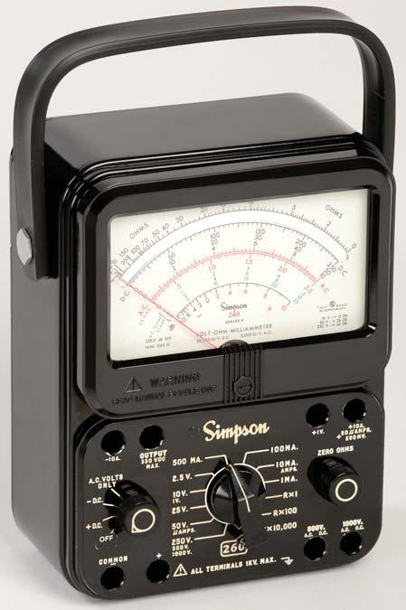
6 1 INTRODUCTION 1.1 General Description The Simpson Volt-Ohm-Milliammeter 260 Series 8, (hereafter referred to as the 260 or as the Instrument) is a rugged, accurate, compact, easy-to-use Instrument equipped with mirrored dial to eliminate parallax. The Instrument can be used to make accurate measurements of AC and DC voltage, direct current, resistance, decibels, and Output Voltage. The Output Voltage function is used for measuring the AC component of a mixture of AC and DC voltage. This occurs primarily in amplifier circuits. New Features in the are: 0-25V AC/DC Range Mirrored Dial 1.2 Overload Protection No single protective device nor even a combination of devices as found in the 260 can fully protect a multi-purpose Instrument under all overload conditions. Overloads of such severity as to damage the Instrument despite all the built-in protection provided are possible when the Instrument is misused. The has been designed to afford maximum instrument protection under overload conditions which might occur within the measuring capabilities of the Instrument, however, the operator must exercise care to avoid severe overloads, particularly when working in high voltage circuits. Basic overload protection is provided by a small inexpensive and easily obtainable 3 AG type, 1 Amp, quick-blow fuse. This fuse is rated to interrupt circuit voltages up to 250 V. For maximum protection it is important to replace the 1A fuse with the Littlefuse type only. A supplemental high energy fuse is provided for additional protection from severe overloads. This fuse is rated for an interruption capacity of 10,000 Amps up to 600 V. (Littlefuse Type BLS or Bussman Type BBS). If the Instrument fails to indicate a reading, the 1 Amp or the 2 Amp fuse may be burned out. (Refer to paragraph 5.4 for fuse replacement.) A 1 Amp spare fuse is furnished with each Instrument. Fuses are located in the battery and fuse compartment. NOTE: The 0-10A range is not fused. The shunt connects directly to the 10A and +10A jacks. Two diodes connected across the meter movement affords protection to the movement by circumventing excessive current around the movement in the event of an overload. 6
7 1.3 Internal Batteries There are two batteries in the ohmmeter circuits. One is a NEDA 13F size D cell that furnishes 1.5-volts for the R X 1 and R X 100 ranges. A NEDA 1604 battery furnishes 9-volts for the R X 10,000 range. The 1.5-volt D cell is held in place with two spring clips which also serve as battery contacts. The polarity symbols for the D cell are marked near the battery contacts. The 9-volt battery is held in place with a spring clip, but contact is made with a separate connector that is polarized. Always observe correct polarity when replacing the 1.5-volt D cell. 1.4 Printed Circuit Most of the component parts are mounted on a printed circuit board which simplifies assembly and maintenance, thus, extending the useful life of the Instrument. 1.5 Phenolic Case The phenolic case is designed with heavy reinforced walls for maximum durability and provides excellent protection for the circuit components. Access to the batteries and fuses are obtained by unscrewing a single captivated screw at the bottom of the case and sliding out the compartment cover. Rubber plug bumpers on the bottom of the case reduce sliding should the 260 be accidentally pulled by the test leads when the Instrument is on a workbench. 1.6 Adjust-A-Vue Case A carrying handle is attached to the Instrument case. The handle may be used to support the Instrument in a convenient sloping position for easy viewing. The case can also be placed in either a vertical or horizontal position. The horizontal position is preferable for greater accuracy since the Instrument is calibrated in this position. 1.7 Test Leads Each Instrument is furnished with one pair (Catalog Number 00043) of probe type test leads (one red and one black, each 48 inches long) for all applications of the Instrument. These test leads have elbow prods on one end, to connect the leads to the recessed jacks on the Instrument front panel. The probe tips at the opposite end have threaded shoulders to accept the screw-on insulated alligator clips (furnished with the test leads) or the 5000 volt test probe(s) to extend the Instrument AC or DC voltage range. The test leads and the insulated alligator clips are rated for the voltage and current ranges available on the 260. Maximum ratings are 1000V AC or DC or 10 DC amperes. THESE RATINGS FOR THE TEST LEADS MUST NOT BE EXCEEDED IN ANY APPLICATION. 7
8 1.8 Technical Data Table 1-1 lists the technical data for the TABLE 1-1. Technical Data 1. DC VOLTS: Ranges: V Sensitivity: 20,000 ohms per volt 2. DC MILLIVOLTS: Range: 0-250mV Sensitivity: 20,000 ohms per volt 3. AC VOLTS: Ranges: V Sensitivity: 5,000 ohms per volt 4. OUTPUT VOLTAGE (AC): Ranges: (limited to 350 VDC) 5. DC MICROAMPERES: Range: 0-50μA Voltage Drop: 250mV 6. DC MILLIAMPERES: Ranges: ma Voltage Drop (Approx.): 250 mv, 255 mv, 300 mv, 500 mv 7. DC AMPERES: Range: 0-10A Voltage Drop (Approx.): 255 mv 8. NOTE: The 10A range is not internally fused. RESISTANCE R X 1 R X 100 R X 10,000 Range 0-2, , M Center Reading ,000 Nominal Open Circuit Voltage 1.5V 1.5V 9V Nominal Short Circuit Current 125mA 1. 25mA 75μA 9. * ACCURACY: DC Voltage Ranges: 2% of Full Scale DC Current: 0-50 μa Range: 1.5% of Full Scale Other Ranges: 2% of Full Scale **AC Voltage Ranges: 3% of Full Scale Frequency Response: Referenced to 100 Hz (Figures 4-4 and 4-9) Resistance Ranges: R X 1: 2.5 of Arc R X 100: 2 of Arc R X 10,000: 2 of Arc * Accuracies specified are for the 260 in a horizontal position. 8
9 10. DECIBELS: Range: Reference Level: 20 to +10 db, 8 to +22 db, 0 to +30 db, +6 to +36 db, +20 to +50 db With zero db power level equal to 1 mw across a 600V line. 11. BATTERIES: Voltage: 1.5V, 9V NEDA No.: 13F, FUSE: F1 1A, 250V, type 3AG, quickacting Littlefuse Type , F2 2A, 600V Littlefuse Type BLS or 2A 600V, Bussman Type BBS. 13. TEST LEADS: 1 red, 1 black, 48" long. 14. SIZE: 5½ x 7" x 3 (13.34 x x 7.94 cm) 15. WEIGHT: 3 lbs. (1.359 kg) 16. RATED-CIRCUIT-TO- GROUND VOLTAGE: 1000V AC/DC Max. ***Per ANSI C 39.5 April 1974: The specified voltage with respect to ground, which may be safely and continuously applied to the circuit of an Instrument. 1.9 Definition of Accuracy The voltage and current accuracy of this Instrument is commonly expressed as a percent of full scale. This should not be confused with accuracy of reading (indication). For example, +2% of full scale on the 10 volt range allows an error of ±0.20V at any point on the dial. This means that at full scale, the accuracy reading would be ±2%, but at half scale it would be ±4%. Therefore, it is advantageous to select a range which gives an indication as near as possible to full scale Safety Considerations This Operator s Manual contains cautions and warnings alerting the user to hazardous operating and service conditions. This information is flagged by CAUTION or WARNING headings throughout the publication, where applicable, and is defined at the front of the manual under SAFETY SYMBOLS. To ensure the safety of operating and servicing personnel and to retain the operating conditions of the Instrument, these instructions must be adhered to. 9
10 TABLE 1-2. Items and Accessories Furnished with this Instrument Quantity 1 *1 * Description Test Lead Set one red and one black (4 ft. long) each with combination probe tip and removable rubber-sleeved alligator clip. 1.5 Volt, D Cell, NEDA 13F 9.0 Volt Cell, NEDA Amp, 250V Fuse, Littlefuse Type # A, 600V Fuse, Littlefuse Type BLS or (Bussman Type BBS) Operator s Manual Number TABLE 1-3. Additional Accessories Description Catalog Number Deluxe Case Model Amp-Clamp Accessory AC High Voltage Probe The 10,000 V AC accessory probe is similar to the high voltage DC probes with the following exceptions: The AC high voltage probe is designed to extend the AC voltage range. The probe can be used with the Simpson volt AC range. NOTE: Instructions are furnished with each high voltage probe. AMP-CLAMP MODEL The Simpson Amp-Clamp Model allows AC current measurements without breaking the circuit under test. The Amp-Clamp works in effect as a transformer containing a split core for accommodating the conductor which carries the current being measured. The current carrying conductor becomes the transformer pri- 10
11 mary and a coil in the Amp-Clamp serves as the secondary winding. The Amp- Clamp output voltage is proportional to the current measured and can be applied to the as an AC voltage. The Amp-Clamp has a range selector with 6 positions. Any of the following current ranges can be used with the 260-8: 5, 10, 25, 50, 100 or 250 amperes. NOTE: Instructions are furnished with each Amp-Clamp. 11
12 2 INSTALLATION 2.1 General This section contains information and instructions for the installation and shipping of the Simpson Included are unpacking and inspection procedures, warranty, shipping, power source requirements and operating position. 2.2 Unpacking and Inspection Examine the shipping carton for obvious signs of damage. If damage is noted, notify the carrier and supplier and do not attempt further use of the Instrument. If Instrument appears to be in good condition, read Operator s Manual in its entirety. Become familiar with the Instrument as instructed in the manual, then proceed to check the electrical performance as soon as possible. Also, check that all items listed in Table 1-2 are included with the Instrument. After unpacking the Instrument, a 1.5V battery and a 9V battery may be found in separate envelopes in the box with the Instrument and the test leads. Two alligator clips for the test leads are in a polyethylene bag. (See Section V for instructions on how to open the battery compartment and install the batteries.) 2.3 Warranty The Simpson Electric Company warranty policy is printed in the front of this manual. Read it carefully prior to requesting any warranty repairs. For assistance of any kind, including help with the Instrument under warranty, contact the nearest Authorized Service Center for instructions. If it is necessary to contact the factory directly, give full details of any installation difficulty and include the Instrument model number, series number, and date of purchase. Service data or shipping instructions will be mailed promptly. If an estimate of charges for non-warranty or other service work is required, a maximum charge estimate will be quoted. This charge will not be exceeded without prior approval. Pack the Instrument carefully and ship it prepaid and insured to the proper destination. 2.4 Power Source Requirements There are two batteries in the ohmmeter circuits: One is a NEDA 13F D size cell that furnishes 1.5 volts for the R X 1 and R X 100 ranges. A NEDA 1604 battery furnishes 9 volts for the R X 10,000 range. The 1.5 volt D cell is held in place with two spring clips which also serve as battery contacts. The 9-volt battery is held in place with a spring clip but contact is made with a separate connector that is polarized. (Always observe correct polarity when replacing the 1.5-volt D cell.) 2.5 Operating Position A handle is attached to the side of the Instrument case. The handle may be used to support the Instrument in a convenient, sloping position for easy viewing. The VOM case can also be placed either in a vertical or horizontal position. The horizontal position is preferable for greater accuracy since the Instrument is calibrated in this position. 12
13 3 CONTROLS, JACKS AND INDICATORS 3.1 General The functions of all the controls, jacks and indicators used to operate the Simpson are described in this section. Become familiar with each item prior to operating the Instrument. 3.2 Front Panel Description Figure 3-1 depicts the front panel controls, jacks and indicators described below. 1 D.C. OHMS A.C. 2.5 V.A.C. DB A.C. OHMS D.C Front Panel: The Volt-Ohm- Milliammeter is a large, easy-to-read 4¼ inch indicating Instrument. Below the Instrument are four controls and eight circuit jacks. 2. Range Switch: This switch may be rotated in either direction to select any one of the available voltage, current, or resistance ranges. -10 A. OUTPUT 350 VDC A.C. VOLTS 500 MA. 100MA. MAX. ONLY 2.5 V. 10MA. AMPS. - D.C. 10 V. 1MA. 1V. 25 V. R x 1 + D.C A. AMPS. R X I00 OFF 250 V. R x I0, V. COMMON I000 V ALL TERMINALS 1 V MAX ZERO OHMS FIGURE 3-1. Front Panel Controls, Jacks and Indicators 2 +1V. +10A + 50 AMPS. 250 MV. 500 V. A.C. D.C V. A.C. D.C. 3. Function Switch: The function switch has four positions: Off, +DC, DC, and AC Volts Only. To measure DC current or voltage, set the function switch at the DC or +DC position, depending on the polarity of the input signal. To measure AC voltage set the function switch to the AC position. For resistance measurement, the switch may be set in either the +DC or DC position. The polarity of the test voltage will be as marked at the jacks when the switch is in the +DC position and reversed in the DC position. Set this switch to off when not using the meter to take measurements. 4. Zero Ohms: This control is used when measuring resistance to calibrate the ohms range selected to read zero with the test leads shorted. Refer to paragraph Circuit Jacks: There are eight jacks on the front panel marked with the functions they represent. These jacks provide the electrical connections to the test leads. The COMMON ( ) jack is used as the reference point for the measurement of all the functions with the exception of the 10A range. (Refer to the Operation Section for details.) 6. Pointer Adjust For Zero: This control is used to mechanically zero the Instrument. With the function switch set to an operating position (+DC, DC, or AC volts only), and no applied input, the pointer should read zero. If it does not, use a screwdriver to turn this adjustment until it does. Once this adjustment is made, back off slightly so the pointer will rest freely over the zero mark. 13 4
14 4 OPERATION Multi-function instruments (VOM s) such as the are intended as general purpose measuring Instruments for use in low power circuitry such as found in consumer appliances, TV and radio receivers, and in general laboratory applications. Their use is not recommended in high voltage, high power circuitry where operator errors and inadequate personal protective measures could result in serious injury from arcing or explosion. Such circuitry is found in industrial or commercial applications such as induction (r-f) heaters and broadcast transmitters, power substations and distribution centers, x-ray equipment, large motor controls and the like. Working in the high voltage section of such equipment requires single-function, often specially designed instruments used by specially trained personnel using appropriate protective equipment and procedures. 4.1 General This section of the manual contains information required to use and operate the in a safe and proper manner. 4.2 Safety Precautions The following precautions are suggestions and reminders of commonly recognized safe practices and specific hazards to be avoided and are not implied to be sufficient to ensure the safety of untrained personnel in all circumstances. Neither is this manual a substitute for technical manuals covering the equipment in which measurements are to be made. Always refer to the equipment manual and its specific warnings and instructions and observe them as well as those contained herein. a. The should only be used by personnel qualified to recognize shock hazards and trained in the safety precautions required to avoid possible injury. b. Do not connect any terminal of this Instrument to a circuit point at which a voltage exceeding 1000 volts AC or DC may exist with respect to earth ground. (Refer to Table 1-1, item 16.) c. Turn off power and discharge any capacitors in the circuit to be measured before connecting to or disconnecting from it. d. Prior to using this Instrument, check accessories (if any) and test leads for missing, damaged, deteriorated or otherwise faulty insulating parts. Do not use, or permit the use of equipment with faulty insulation until it has been properly repaired. e. Always wear safety glasses when working in electrical circuitry. f. Do not work alone on high voltage circuits. Make certain that someone capable of rendering aid is nearby and watchful. g. Do not handle the Instrument, its test leads, or the circuitry while high voltage is being applied. h. Hands, shoes, floor, and workbench must be dry. Avoid making measurements under humid, damp, or other environmental conditions that could effect the dielectric withstanding voltage of the test leads or Instrument. i. Do not change switch settings or test lead connections while taking measure- 14
15 ments. A mistake could result in damage to the Instrument and possible personal injury. j. Locate all voltage sources and accessible current paths before making connections to circuitry. High voltage may appear unexpectedly or in unexpected locations in faulty equipment. An open bleeder resistor, for example, may result in a capacitor retaining a dangerous charge. k. Make certain that the equipment being worked upon is properly grounded and fuses are of the proper type and rating. l. Check and double check switch positions and jack connections before applying power to the Instrument. m. Always remain alert for low voltage circuits which may be floating at high voltage with respect to earth ground and for composite voltages (AC + DC) such as are found in r-f amplifiers. The floating voltage or composite voltage must not exceed the Instrument s rated maximum circuit-to-ground voltage. n. Do not make electrical measurements where the air may contain explosive concentrations of gas or dust such as in mines, grain elevators, gasoline stations or in the presence of charging batteries until determined to be safe by qualified personnel. Note that even metallic dusts can be explosive. o. No General Purpose VOM is to be used to make electrical measurements on blasting circuits or blasting caps. Use only VOM s designed for this purpose. 4.3 Polarity Reversing The function switch provides a convenient means to reverse polarity of the internal battery to facilitate testing semiconductor devices. The +DC and DC positions transpose internal connections to the COMMON and +jacks and therefore can also be used to reverse polarity of external voltages and currents connected to these jacks (only). Because polarity reversing momentarily interrupts the circuit, it should not be done while measuring current or voltage without first turning off the circuit power. When making measurements on the 50mA/250mV, 1 volt, or 10 amp range, polarity can be corrected only by reversing the test leads. 4.4 Measurement of Unknown Voltage or Current Sometimes the approximate voltage or current to be measured is known and the correct range may easily be selected. It is often the case, however, particularly when working upon faulty equipment, when the voltage or current is either unknown or may be much higher than normal and anticipated. Whenever working upon unfamiliar or unknown equipment, always begin a measurement using the highest range available on the Instrument. Once it is determined that the voltage is within the limits of a lower range, change to the lower range. 4.5 Test Leads These are provided with accessory screw-on alligator clips which may be attached to the probe tips. Aside from the convenience of eliminating the need to handhold test prods to a circuit for extended periods, the test clips provide a means of reducing hand proximity to a high voltage circuit while energized. Circuit power must of course be turned off and any charged capacitors discharged before connecting or disconnecting clips to or from the current. 15
16 4.6 DC Voltage Measurement 0-250mV Range Prior to making voltage measurements, review the SAFETY PRE- CAUTIONS listed in paragraph 4.2. Also, when using the 260 as a millivoltmeter, care must be taken to prevent damage to the indicating instrument from excessive voltage. Before using the 250 millivolt range, use the 1.0-volt DC range to determine that the voltage measured is not greater than 250 millivolts (or.25 volt DC). a. Set the function switch at +DC (Figure 4-1). b. Plug the black test lead in the COMMON jack and the red test lead into the +50 μa/250mv jack. c. Set the range switch at 50 μa (common position with 50V). d. Connect the black test lead to the negative side of the circuit being measured and the red test lead to the positive side of the circuit. e. Read the voltage on the black scale marked DC and use the figures marked Read directly in millivolts. NOTE: For polarity reversing see paragraph DC Voltage Measurement 0-1V Range a. Set the function switch at +DC (Figure 4-1). D.C. D.C. b. Plug the black test lead into the COM- MON jack and the red test lead into the +1V jack. c. Set the range switch at 1V (common position with 10V). - D.C. + D.C. COMMON V. 10 V. 1V. 25 V. 50 A. AMPS. 250 V. 500 V. I000 V. 260 ALL TERMINALS 1 V MAX +1V. +10A + 50 AMPS. 250 MV. Figure 4-1. Jacks and Switch Positions for Measuring DC Voltages, 0 through 250V Ranges d. Connect the black test lead to the negative side of the circuit being measured and the red test lead to the positive side of the circuit. e. Read the voltage on the black scale marked DC and use the figures marked Then divide the reading by 10. NOTE: For polarity reversing see paragraph
17 4.8 DC Voltage Measurement ~ 0-250V Range a. Set the function switch at +DC (Figure 4-1). b. Plug the black test lead into the COMMON jack and the red test lead into the + jack. c. Set the range switch at one of the five voltage range positions marked 2.5V, 10V, 25V, 50V or 250V. NOTE: When in doubt as to the voltage present, always use the highest voltage range as a protection to the Instrument. If the voltage is within a lower range, the switch may be set for the lower range to obtain a more accurate reading. Be sure power is off in the circuit being measured and all capacitors discharged. d. Connect the black test lead to the negative side of the circuit being measured and the red test lead to the positive side of the circuit. e. Turn on the power in the circuit being measured. f. Read the voltage on the black scale marked DC. For the 2.5V range, use the figures and divide by 100. For the 10V, 50V, and 250V ranges, read the figures directly. For the 25V range, use the figures and divide by 10. NOTE: Turn off power to the circuit and wait until the meter indicates zero before disconnecting the test leads. 4.9 DC Voltage Measurement 0-500V Range! Be extremely careful when working with high voltage circuits. Do not touch the Instrument or test leads while power is on in the circuit being measured. Before proceeding with the following steps, review the Safety Precautions in D.C. + D.C. D.C. COMMON V. 500 V. I000 V. 260 ALL TERMINALS 1 V MAX 500 V. A.C. D.C. FIGURE 4-2. Jacks and Switch Positions for Measuring DC Voltage, 0-500V Range D.C. a. Set the function switch at +DC (Figure 4-2). b. Set the range switch at the 250V/500V/ 1000V position. c. Plug the black test lead into the COM- MON jack and the red test lead into the 500V jack. d. Be sure power is off in the circuit being measured and all capacitors discharged. Connect the black test lead to the negative side of the circuit being measured and the red test lead to the positive side of the circuit. e. Turn on power in circuit being measured. f. Read the voltage using the 0-50 figures on the black scale marked DC. Multiply the reading by 10. NOTE: Turn off power to the circuit and wait until the meter indicates zero before disconnecting the test leads. 17
18 4.10 DC Voltage Measurement V Range! Be extremely careful when working with high voltage circuits. Do not touch the Instrument or test leads while power is on in the circuit being measured. Before proceeding with the following steps, review the Safety Precautions in D.C. + D.C. D.C. COMMON V. 500 V. I000 V. 260 ALL TERMINALS 1 V MAX FIGURE 4-3. Jacks and Switch Positions for Measuring DC Voltage, V Range D.C V. A.C. D.C. a. Set the function switch at +DC (Figure 4-1). b. Set the range switch at the 250V/500V/ 1000V position. c. Plug the black test lead into the COM- MON jack and the red test lead into the 1000V jack. d. Be sure power is off in the circuit being measured and all capacitors discharged. Connect the black test lead to the negative side of the circuit being measured and the red test lead to the positive side of the circuit. e. Turn on power in circuit being measured. f. Read the voltage using the 0-10 figures on the black scale marked DC. Multiply the reading by 100. NOTE: Turn off power to the circuit and wait until the meter indicates zero before disconnecting the test leads. PERCENT RELATIVE ERROR AC VOLTAGE RANGES 2.5 VAC RANGE 10VAC RANGE 50 VAC RANGE 250 VAC RANGE 500 VAC RANGE 1000 VAC RANGE A.C. 2.5 V.A.C. A.C A.C. VOLTS ONLY 2.5 V. 10 V. 1V. 25 V. 50 A. AMPS. 10Hz 100Hz 1KHz 10KHz 100KHz FREQUENCY COMMON V. 500 V. I000 V. 260 ALL TERMINALS 1 V MAX FIGURE 4-4. Frequency Response, AC Voltage Ranges FIGURE 4-5. Jacks and Switch Positions for Measuring AC Voltage through 0-250V Ranges 18
19 AC Voltage Measurement ~ 0-250V Range! Branch and distribution circuits (120/240/480V etc.) can deliver dangerous explosive power momentarily into a short circuit before the fuse/breaker opens the circuit. Make absolutely certain that the Instrument switches are set properly, jacks are connected properly, and that the circuit power is turned off before making connections to such circuits. The 260 responds to the average value of an AC waveform. It is calibrated in terms of the RMS value of a pure sine wave. If the waveform is nonsinusoidal, and depending upon its waveform, the reading may be either higher or lower than the true RMS value of the measured voltage. Thus an error may be introduced if the 260 is used to measure a nonsinusoidal waveform. Also, accuracy is lessened at higher input frequencies (Figure 4-4). Before proceeding with the following steps, review the Safety Precautions in Paragraph 4.2. a. Set the function switch to AC Volts Only position (Figure 4-5). NOTE: The meter will not indicate if the switch is incorrectly set to a DC position. b. Set the range switch at one of the five voltage range positions marked 2.5V, 10V, 25V, 50V or 250V. (When in doubt as to actual voltage present, always use the highest voltage range as a protection to the Instrument. If the voltage is within a lower range, the switch may be set for the lower range to obtain a more accurate reading.) A.C. A.C. A.C. 10 A.C. A.C. VOLTS ONLY COMMON V. 10 V. 1V. 25 V. 50 A. AMPS. 250 V. 500 V. I000 V. 260 ZERO OHMS 500 V. A.C. D.C. A.C. VOLTS ONLY COMMON V. 10 V. 1V. 25 V. 50 A. AMPS. 250 V. 500 V. I000 V. 260 ZERO OHMS 500 V. A.C. D.C. ALL TERMINALS 1 V MAX ALL TERMINALS 1 V MAX FIGURE 4-6. Jacks and Switch Positions for Measuring AC Voltage Through 0-250V Ranges 19 FIGURE 4-7. Jacks and Switch Positions for Measuring AC Voltage 0 Through 1000V Range
20 c. Plug the black test lead into the COMMON jack and the red test lead into the + jack. d. Turn off power to the circuit to be measured and discharge any capacitors. e. Connect the test leads across the circuit voltage to be measured with the black lead to the grounded side. f. For the 2.5V range read the value directly on the scale marked 2.5 VAC. For the 10V, 25V, 50V and 250V ranges, read the red scale marked AC and use the black figure immediately above the scale AC Voltage Measurement 0-500V Range Be extremely careful when working in high voltage circuits. Do not handle the Instrument or test leads while the circuit being measured is energized. OBSERVE ALL SAFETY PRECAUTIONS in paragraph 4.2 and in the instruction manual for the equipment being tested. Do not attempt any voltage measurement which may exceed 1000 volts or the circuit-to-ground voltage of the Instrument, 1000 volts maximum. Be sure that the range switch is set to the 250V/500V/1000V range, function switch to AC volts only position, and test leads connected to common and 500V jack. Do not touch the Instrument or test leads while the power is on the circuit being measured. Before proceeding with the following steps, review the Safety Precautions in Paragraph 4.2. a. Set the function switch to AC Volts Only position (Figure 4-6). When making AC voltage measurements with the function switch incorrectly set to DC, the Instrument pointer will remain at or near zero, indicating a false no voltage present condition that could be hazardous. b. Set the range switch at 250V/500V/1000V position. c. Plug the black test lead into the COMMON jack and the red test lead in the 500V jack. d. Be sure the power is off in the circuit being measured and that all its capacitors have been discharged. e. Connect the test leads across the circuit voltage to be measured with the black lead to the grounded side. f. Turn on the power in the circuit being measured. g. Read the voltage on the red scale marked AC. Use the 0-50 figures and multiply by
21 4.13 AC Voltage Measurement V Range Be extremely careful when working in high voltage circuits. Do not handle the Instrument or test leads while the circuit being measured is energized. OBSERVE ALL SAFETY PRECAUTIONS in paragraph 4.2 and in the instruction manual for the equipment being tested. Do not attempt any voltage measurement which may exceed 1000 volts or the circuit-to-ground voltage of the Instrument, 1000 volts maximum. Be sure that the range switch is set to the 250V/500V/1000V range, function switch to AC Volts Only position, and test leads connected to common and 1000V jack. Do not touch the Instrument or test leads while the power is on in the circuit being measured OUTPUT RANGES 2.5 VAC RANGE 10VAC RANGE 25/50 VAC RANGE 250 VAC RANGE A.C. A.C A.C. VOLTS ONLY OUTPUT 350 VDC MAX. 2.5 V. 10 V. 1V V. 50 A. AMPS. -10 COMMON V. 500 V. I000 V Hz 100Hz 1KHz 10KHz 100KHz 1MHz FREQUENCY FIGURE 4-8. Frequency Response Output Ranges ALL TERMINALS 1 V MAX FIGURE 4-9. Jacks and Switch Positions for Output Measurements Before proceeding with the following steps, review the Safety Precautions in Paragraph 4.2. a. Set the function switch at AC (Figure 4-7). b. Set the range switch at 250V/500V/1000V position. c. Plug the black test lead into the -COMMON jack and the red test lead in the 1000V jack. d. Be sure the power is off in the circuit being measured and that all its capacitors have been discharged. e. Connect the test leads across the circuit voltage to be measured with the black lead to the grounded side. f. Turn on the power in the circuit being measured. g. Read the voltage on the red scale marked AC. Use the 0-10 figures and multiply by
22 D.C. D.C. DB A.C. VOLTS ONLY 2.5 V. 10 V. 1V. -10 A. OUTPUT 350 VDC A.C. VOLTS MAX. ONLY - D.C. 500 MA. 100MA. 10MA. AMPS. 1MA. +1V. +10A + 50 AMPS. 250 MV. COMMON V. 50 A. AMPS. 250 V. 500 V. I000 V D.C. OFF COMMON A. AMPS. 260 ALL TERMINALS 1 V MAX ALL TERMINALS 1 V MAX FIGURE Jacks and Switch Positions for Measuring Decibels Output Voltage Measurement FIGURE Jacks and Switch Positions for Measuring Direct Current It is often desired to measure the AC component of an Output Voltage where both AC and DC voltage levels exist. This occurs primarily in amplifier circuits. The has a 0.1 mfd, 400 volt capacitor in series with the OUTPUT jack. The capacitor blocks the DC component of the current in the test circuit, but allows the AC or desired component to pass on to the indicating instrument circuit. The blocking capacitor may alter the AC response at low frequencies but is usually ignored at audio frequencies (Figure 4-8). Do not connect the OUTPUT jack to a circuit in which the DC voltage component exceeds 350V. Before proceeding with the following steps, review the Safety Precautions in Paragraph 4.2. a. Set the function switch to AC volts only position (Figure 4-9). b. Plug the black test lead into the -COMMON jack and the red test lead into the OUTPUT jack. c. Set the range switch at one of the range positions marked 2.5V, 10V, 25V, 50V, or 250V. d. Connect the test leads across the circuit being measured with the black test lead to the ground side. e. Turn on the power in the test circuit. Read the output voltage on the appropriate AC voltage scale. For the 0-2.5V range, read the value directly on the scale marked 2.5 VAC. For the 10V, 25V, 50V, or 250V ranges, use the red scale marked AC and read the black figures immediately above the scale. 22
23 4.15 Decibel Measurement ( 20 to +50 db) In some industries, measurements are made in terms of voltage or current ratios (decibels) based on a specific reference level. The db scale on the serves this purpose and is calibrated to a reference level (zero db) of watt into 600 ohms. The scale calibration of 20 to +10 db is for the 0-2.5V range (zero db = 0.775V). Higher ranges may be used by adding an appropriate db value to the reading in accordance with the chart on page 14. a. Review the safety precautions in paragraph 4.2. b. Refer to Figure 4-10 for switch settings and jack connections. c. Use operating instructions for AC VOLTAGE MEASUREMENT, 0-2.5/10/25/ 50/250V RANGES (paragraph 4.9). Do not use the 500V or 1000V ranges for decibel readings. d. Read decibels on the bottom scale marked db. For the 10/25/50/250V ranges, add the appropriate factor from the chart below: Voltage Range db Range 0-2.5V -20 to + 10 read directly Reading 0-10V -8 to + 22 add +12 db to reading 0-25V 0 to 30 add +20dB to reading 0-50V + 6 to + 36 add 26 db to reading 0-250V + 20 to + 50 add 40dB to reading NOTE: The maximum voltage ratio that can be measured is +50 db on the 0-250V range. e. If db measurements are being made to a watt into 500 ohm reference level, subtract +7 db from the reading obtained on the Direct Current Measurement DO NOT CHANGE THE RANGE SETTING OF THE RANGE OR FUNCTION SWITCHES WHILE THE CIRCUIT IS ENERGIZED. NEVER DISCONNECT TEST LEADS FROM THE CIRCUIT UNDER MEA- SUREMENT WHILE IT IS ENERGIZED.! ALWAYS TURN THE POWER OFF AND DISCHARGE ALL THE CAPACITORS BEFORE THE SETTING OF THE SWITCHES IS CHANGED, OR THE LEADS DISCONNECTED. NEVER EXCEED THE CIRCUIT-TO-GROUND VOLTAGE OF THE INSTRU- MENT (1000 V MAX., TABLE 1-1, ITEM 16). ALWAYS CONNECT THE INSTRUMENT IN SERIES WITH THE GROUND SIDE OF THE CIRCUIT. IN ALL DIRECT CURRENT MEASUREMENTS, MAKE CERTAIN THE POWER TO THE CIRCUIT BEING TESTED HAS BEEN TURNED OFF BEFORE CON- NECTING AND DISCONNECTING TEST LEADS OR RESTORING CIRCUIT CONTINUITY. 23
24 4.17 Direct Current Measurement 0-50μA Range a. Set the function switch at +DC. b. Plug the black test lead into the COMMON jack and the red test lead into the +50μAMPS/250mV jack. c. Set the range switch at 50μAMPS (dual position with 50V). d. Open the ground side of the circuit in which the current is being measured. Connect the VOM in series with the circuit. Connect the red test lead to the positive side and the black test lead to the negative side. e. Read the current on the black DC scale. Use the 0-50 figures to read directly in microamperes. NOTE: For polarity reversing see paragraph Direct Current Measurement 0-1mA through 0-500mA range a. Set the function switch at +DC (Figure 4-11). b. Plug the black test lead into the COMMON jack and the red test lead into the + jack. c. Set the range switch at one of the four range positions marked 1 ma, 10 ma, 100 ma or 500 ma. d. Open the grounded side of the circuit in which the current is being measured. Connect the VOM in series with the circuit. Connect the red test lead to the positive side and the black test lead to the negative side. e. Turn the power on. Read the current in milliamperes on the black DC scale. For the 1 ma range, use the 0-10 figures and divide by 10. For the 10 ma range, use the 0-10 figures directly. For the 100 ma range, use the 0-10 figures and multiply by 10. For the 500 ma range, use the 0-50 figures and multiply by 10. f. Turn the power off and disconnect the test leads. This range is only intended for measurements in low voltage circuits (under 25 V DC) such as the primary power in vehicles or their accessories Direct Current Measurement 0-10A range a. Plug the black test lead into the 10A jack and the red test lead into the +10A jack. b. Set the range switch at 10 AMPS (dual position with 10 ma). c. Open the ground side of the circuit in which the current is being measured. Connect the VOM in series with the circuit, connecting the red test lead to the positive side and the black test lead to the negative side. NOTE: The function switch has no effect on polarity for the 10 AMPS range. 24
25 d. Turn the power on. Read the current directly on the black DC scale. Use the 0-10 figures to read directly in amperes. e. Turn the power off and disconnect the test leads.! The 10A range is not internally fused in the When using the 10A range, never disconnect a test lead from a jack or from the circuit while the circuit is energized. Doing so may likely damage the test jacks or leads and the arcing may be hazardous to the operator. Turn off circuit power and wait for the meter reading to drop to zero. The polarity reversing feature of the function switch does not operate on the 0-10A range. If polarity is found to be incorrect, turn off circuit power, wait for the meter indication to reach zero and then interchange test lead connections to the circuit Resistance Measurements Voltage applied to a resistance range will cause reading errors if low and damage the Instrument if high. When making in-circuit measurements, make certain that the circuit is completely de-energized before making connections to it. When making in-circuit measurements, circuit paths in parallel with the resistance being measured may cause reading errors. Check circuit diagrams for the presence of such components before assuming that the reading obtained is correct. When resistance is measured, the batteries furnish power for the circuit. Since batteries are subject to variation in voltage and internal resistance, the Instrument must be adjusted to zero before measuring a resistance, as follows: a. Turn range switch to desired ohms range. b. Plug the black test lead into the COMMON jack and the red test lead into the + jack. c. Connect the ends of test leads together to short the VOM resistance circuit. d. Rotate the ZERO OHMS control until pointer indicates zero ohms. If pointer cannot be adjusted to zero, one or both of the batteries must be replaced. (For battery replacement, refer to Section V.) e. Disconnect shorted test leads. 25
26 4.21 Measuring Resistance a. Before measuring resistance in a circuit, make sure the power is off to the circuit being tested and all capacitors are discharged. Disconnect shunting components from the circuit before measuring its resistance. b. Set the range switch to one of the resistance range positions as follows (Figure 4-12): 1. Use R X 1 for resistance readings from 0 to 200 ohms. 2. Use R X 100 for resistance readings from 200 to 20,000 ohms. 3. Use R X 10,000 for resistance readings above 20,000 ohms. c. Set the function switch at either DC or +DC position: Operation is the same in either position except if there are semiconductors in the circuit. (See paragraph 4.22.) Adjust ZERO OHMS control for each resistance range. d. Observe the reading on the OHMS scale at the top of the dial. NOTE: The OHMS scale reads from right to left for increasing values of resistance. e. To determine the actual resistance value, multiply the reading by the factor at the switch position. (K on the OHMS scale equals one thousand.) 4.22 Resistance Measurement of Semiconductors Make sure that the OHMS range being used will not damage any of the semiconductors (refer to Table 1-1, item 8, Section I). If there is a forward and backward resistance such as in diodes, the resistance should be relatively low in one direction (for forward polarity) and higher in the opposite direction. Rotate the function switch between the two DC positions to reverse polarity. This will determine if there is a difference between the resistance in the two directions. To check a semiconductor in or out of a circuit (forward and reverse bias resistance measurements) consider the following before making the measurement: a. The polarity of the battery voltage will be as marked at the jacks when the switch is in the +DC position and reversed in the DC position. b. Ensure that the range selected will not damage the semiconductor. (Refer to Table 1-1, item 8, and review the specification limits of the semiconductor according to the manufacturer s ratings.) c. If the semiconductor is a silicon diode or conventional silicon transistor, no precautions are normally required. d. If the semiconductor material is germanium, check the ratings of the device and refer to Table 1-1, item 8. NOTE: The resistance of diodes will measure differently from one resistance range to another on the VOM with the function switch in a given position. For example, a diode which measures 80 ohms on the R X 1 range may measure 300 ohms on the R X 100 range. The difference in values is a result of the diode characteristics and is not indicative of any fault in the VOM. 26
27 OHMS OHMS - D.C. + D.C. COMMON R x 1 R X I00 R x I0,000 ALL TERMINALS 1 V MAX FIGURE Jacks and Switch Positions for Measuring Resistance 5 OPERATOR MAINTENANCE 5.1 General The following paragraphs in this section describe battery replacement, fuse replacement, and preventive maintenance procedures for the Inspection The user is protected from electrical shock by the insulation of the 260 and its test leads. Frequently examine them for any insulation damage such as cracks, cuts, chips, burns or deterioration that expose internal metal parts or reduce the spacing between such metal parts and hand contact by the operator. Make certain that the battery compartment cover is securely fastened in place before the Instrument is used. Do not use an Instrument with a broken meter glass. FIGURE 5-1. Battery and Fuse Compartment LAC DU FLAMBEAU, WI Whenever the battery compartment cover is removed for any reason, check that the proper fuses are being used. 27
28 5.3 Battery Replacement a. Two batteries are used inside the case to supply power for resistance measurements. One is a 1.5-volt D cell and the other is a 9-volt battery. When it is no longer possible to adjust the pointer to zero for the R X 1 and R X 100 ranges (refer to ZERO OHMS ADJUSTMENT paragraph 4.20), replace the 1.5-volt cell. When it is no longer possible to adjust the pointer to zero on the R X 10,000 range, replace the 9-volt battery. b. To install or replace a battery, de-energize and disconnect test leads from the Instrument, then remove the cover to the externally accessible battery compartment by loosening the single captivated screw. NOTE: Batteries should be replaced before their useful life has expired. Failure to do so may result in corrosion and battery leakage. c. Observe polarity when replacing the 1.5-volt D cell and connect as indicated. The D cell is held in place with spring clips which also act as battery contact clips. The 9-volt battery contacts and connector are polarized. To remove the 9-volt battery, first withdraw battery with mated connector from the compartment. Then remove the connector. 5.4 Fuse Replacement The 1 and 2 ampere fuse (also the 1A spare) is located in the externally accessible battery and fuse compartment. Access to the compartment is obtained by disconnecting the test leads and loosening the single captivated screw on the compartment cover. To replace or check a fuse: Apply pressure to the 1 amp fuse cup then rotate the plate to expose a selected fuse for removal from the panel s cavity. NOTE: When replacing fuses, it is important to use the same type and value as the ones you have removed. 5.5 Test Lead Inspection Periodic inspection of the test leads is recommended to detect cuts, burned areas, deterioration or other damage that could reduce the insulation strength of leads. 28
29 5.6 Care Immediately clean all spilled materials from the Instrument and wipe dry. If the spillage is corrosive, use a suitable cleaner to neutralize the corrosive action. Whenever the Instrument is not in use, rotate the function switch to the OFF position. Whenever possible, avoid prolonged exposure or usage in areas which are subject to temperature and humidity extremes, vibration or mechanical shock, dust or corrosive fumes, or strong electrical or electromagnetic interferences. Verify Instrument accuracy by performing operational checks using known, accurate, stable sources. If proper calibration equipment is not available, contact the nearest Authorized Service Center. If the Instrument has not been used for 30 days, check the batteries for leakage and replace if necessary. It is recommended that the Instrument be returned annually to the nearest Authorized Service Center, or to the factory, for an overall check, adjustment, and calibration. When the Instrument is not in use, store it in a room free from temperature extremes, dust, corrosive fumes, and mechanical vibration or shock. If storage time is expected to exceed 30 days, remove batteries. 29
Simpson 260 Series 8P Volt-Ohm-Milliammeters INSTRUCTION MANUAL
 Simpson 260 Series 8P Volt-Ohm-Milliammeters INSTRUCTION MANUAL About this Manual To the best of our knowledge and at the time written, the information contained in this document is technically correct
OPERATOR S MANUAL Model 160 Volt-Ohm-Milliammeter
 OPERATOR S MANUAL Model 160 Volt-Ohm-Milliammeter About this Manual To the best of our knowledge and at the time written, the information contained in this document is technically correct and the procedures
Model 229 Series 2 Leakage Current Tester OPERATOR S MANUAL
 Model 229 Series 2 Leakage Current Tester OPERATOR S MANUAL SIMPSON ELECTRIC COMPANY 52 Simpson Avenue Lac du Flambeau, WI 54538-99 (715) 588-3311 FAX (715) 588-3326 Printed in U.S.A. Part No. 5-11575
Warning, refer to accompanying documents.
 About this Manual To the best of our knowledge and at the time written, the information contained in this document is technically correct and the procedures accurate and adequate to operate this instrument
MODEL TS-113 VOLT-OHM-MILLIAMMETER. Operator s Manual WARNING READ AND UNDERSTAND THIS MANUAL BEFORE USING THE INSTRUMENT
 MODEL TS-113 VOLT-OHM-MILLIAMMETER Operator s Manual WARNING READ AND UNDERSTAND THIS MANUAL BEFORE USING THE INSTRUMENT Failure to understand and comply with the WARNINGS and operating instructions can
Model 228 Current Leakage Tester INSTRUCTION MANUAL
 Model 228 Current Leakage Tester INSTRUCTION MANUAL 1 About this Manual To the best of our knowledge and at the time written, the information contained in this document is technically correct and the procedures
Warning, refer to accompanying documents V CAT II Overvoltage category II device. CSA Canadian Standards Association
 About this Manual To the best of our knowledge and at the time written, the information contained in this document is technically correct and the procedures accurate and adequate to operate this instrument
USER'S MANUAL DMR-6700
 USER'S MANUAL Multimeter True RMS DMR-6700 CIRCUIT-TEST ELECTRONICS www.circuittest.com Introduction This meter measures AC/DC Voltage, AC/DC Current, Resistance, Capacitance, Frequency (electrical & electronic),
OPERATOR S INSTRUCTION MANUAL M-2625 AUTO RANGING DIGITAL MULTIMETER
 OPERATOR S INSTRUCTION MANUAL M-2625 AUTO RANGING DIGITAL MULTIMETER with Temperature Probe Copyright 2007 Elenco Electronics, Inc. Contents 1. Safety Information 3,4 2. Safety Symbols 5 3. Front Plate
User Manual Digital Multimeter
 User Manual Digital Multimeter model no.: MSR-R500 Questions or Concerns? support@etekcity.com visit etekcity.com for more products Safe and Proper Usage Thank you for purchasing the Etekcity MSR-R500
INSTRUCTION MANUAL LKG 601 Electrical Safety Analyzer
 INSTRUCTION MANUAL LKG 601 Electrical Safety Analyzer 110 Toledo Street Farmingdale, NY 11735 USA http://www.netech.org 510-USER-Manual Rev3 10/29/2007 Dear User, We appreciate your purchase of the LKG
Dawson DDM181. Pocket-Size Autorange Digital Meter User s Manual
 Dawson DDM181 Pocket-Size Autorange Digital Meter User s Manual 1 Table of Contents LIMITED WARRANTY AND LIMITATION OF LIABILITY... 3 Out of the Box... 3 Accessories... 4 Important Safety Information...
! Warning, refer to accompanying documents.
 About this Manual To the best of our knowledge and at the time written, the information contained in this document is technically correct and the procedures accurate and adequate to operate this instrument
MS8268 HANDHELD DIGITAL MULTIMETER OPERATOR S INSTRUCTION MANUAL
 MS8268 HANDHELD DIGITAL MULTIMETER OPERATOR S INSTRUCTION MANUAL Table of Contents TITLE PAGE 1. GENERAL INSTRUCTIONS 1 1.1 Precaution safety measures 1 1.1.1 Preliminary 1 1.1.2 During use 2 1.1.3 Symbols
BC145 SIGNAL ISOLATOR BOARD
 BC145 SIGNAL ISOLATOR BOARD 4/17 Installation & Operating Manual MN1373 Any trademarks used in this manual are the property of their respective owners. Important: Be sure to check www.baldor.com to download
DMM8900 SERIES USERS MANUAL
 DMM8900 SERIES USERS MANUAL WARRANTY This instrument is warranted to be free from defects in material and workmanship for a period of one year. Any instrument found defective within one year from the delivery
USER'S MANUAL DMR-2400
 USER'S MANUAL DIGITAL MULTIMETER DMR-2400 CIRCUIT-TEST ELECTRONICS www.circuittest.com TABLE OF CONTENTS SAFETY Safety Information...................................... 2 Safety Symbols........................................
Dawson DDM190. Digital Multimeter User s Manual
 Dawson DDM190 Digital Multimeter User s Manual TABLE OF CONTENTS LIMITED WARRANTY AND LIMITATION OF LIABILITY... 3 Out of the Box... 3 Accessories.. Error! Bookmark not defined. Safety Information... 7
IDEAL INDUSTRIES, INC. TECHNICAL MANUAL MODEL: MODEL: Multimeter Service Information
 IDEAL INDUSTRIES, INC. TECHNICAL MANUAL MODEL: 61-340 MODEL: 61-342 Multimeter Service Information The Service Information provides the following information: Precautions and safety information Specifications
Model : OPERATING MANUAL Table of Contents (1)
") Table of Contents (1) Title Overview Unpacking Inspection Safety Information Rules For Safe Operation International Electrical Symbols The Meter Structure Functional Buttons Measurement Operation A. DC
Table of Contents (1) Title Overview Unpacking Inspection Safety Information Rules For Safe Operation International Electrical Symbols The Meter Structure Functional Buttons Measurement Operation A. DC
INSTALLATION AND MAINTENANCE MANUAL FOR GROUND MONITOR GM-250 COPYRIGHT 1983 AMERICAN MINE RESEARCH, INC.
 INSTALLATION AND MAINTENANCE MANUAL FOR GROUND MONITOR GM-250 COPYRIGHT 1983 AMERICAN MINE RESEARCH, INC. MANUAL PART NUMBER 180-0036 ORIGINAL: 1-17-83 REVISION: B (8-26-86) NOT TO BE CHANGED WITHOUT MSHA
DIGITAL MULTIMETER OPERATOR'S INSTRUCTION MANUAL HOLD 10A COM LIGHT MS8265 ON/OFF. 200M KHz 2K 20K μ μ μ n.
 MS8265 DIGITAL MULTIMETER OPERATOR'S INSTRUCTION MANUAL HOLD ON/OFF LIGHT 1000V CAT II 600V CAT III MS8265 200K 2M 20M 20K 200M KHz 2K 20 200 2 20 200μ 200 20μ 750 2μ 1000 200n F 20n 10A 2m 200m 10 10
HANDHELD DIGITAL MULTIMETER OPERATOR S INSTRUCTION MANUAL
 HANDHELD DIGITAL MULTIMETER OPERATOR S INSTRUCTION MANUAL GENERAL INSTRUCTIONS This instrument complies with IEC 1010-1 (61010-1@IEC: 2001), CAT. II 1000V and CAT. III 600V overvoltage standards. See Specifications.
DIGITAL MULTIMETER OPERATING INSTRUCTIONS MODEL CDM-35. Part No
 DIGITAL MULTIMETER MODEL CDM-35 Part No.4500055 OPERATING INSTRUCTIONS 0304 The Meter may be hung on a wall, or supported as shown, depending upon which support is used. The probes may be located as shown,
DIGITAL DUAL DISPLAY AC/DC CLAMP METER MODEL-860A OPERATION MANUAL
 DIGITAL DUAL DISPLAY AC/DC CLAMP METER MODEL-860A OPERATION MANUAL DIGITAL DUAL DISPLAY AC/DC CLAMP METER MODEL-860A TABLE OF CONTENTS TITLE PAGE Safety Information Safety Symbols... 1 Meter Description...
312, 316, 318. Clamp Meter. Users Manual
 312, 316, 318 Clamp Meter Users Manual PN 1989445 July 2002 Rev.2, 2/06 2002, 2006 Fluke Corporation. All rights reserved. Printed in China. All product names are trademarks of their respective companies.
User Manual Digital Multimeter. model no.: MSR-U1000
 User Manual Digital Multimeter model no.: MSR-U1000 This Operating Manual covers information on safety and cautions. Please read the relevant information carefully and observe all the Warnings and Notes
Simpson Model 899 Sound Level Meter OPERATOR S MANUAL
 Simpson Model 899 Sound Level Meter OPERATOR S MANUAL About this Manual To the best of our knowledge and at the time written, the information contained in this document is technically correct and the procedures
Simpson Model Sound Level Meter OPERATOR S MANUAL
 Simpson Model 886-2 Sound Level Meter OPERATOR S MANUAL About this Manual To the best of our knowledge and at the time written, the information contained in this document is technically correct and the
HHMA2 DC / TRUE RMS AC NON-CONTACT MILLIAMMETER
 HHMA2 DC / TRUE RMS AC NON-CONTACT MILLIAMMETER Instruction Manual Manual UN-01-249 Item 359934 April, 1999 Rev. -- OMEGA Engineering Inc. All rights reserved. This symbol appears on the instrument and
Autoranging Multimeter Extech EX503
 User's Guide Autoranging Multimeter Extech EX503 Introduction Congratulations on your purchase of the Extech EX503 Autoranging Multimeter. This meter measures AC/DC Voltage, AC/DC Current, Resistance,
Table of Contents Title Page
 Table of Contents Title Page Overview Unpacking Inspection Safety Information Rules For Safe Operation International Electrical Symbols The Meter Structure Rotary Switch Functional Buttons Display Symbols
AM-510 Commercial / Residential Multimeter. AM-510-EUR Digital Multimeter. Users Manual
 AM-510 Commercial / Residential Multimeter AM-510-EUR Digital Multimeter Users Manual AM-510 Commercial / Residential Multimeter AM-510-EUR Digital Multimeter English Users Manual Limited Warranty and
80i-110s AC/DC CURRENT PROBE
 Table of Contents 3 80i-110s AC/DC CURRENT PROBE Users Manual November 1996 1994, 1996 Fluke Corporation. All rights reserved. All product names are trademarks of their respective companies. Printed in
INSTRUCTION MANUAL LKG
 INSTRUCTION MANUAL LKG 610 Electrical Safety Analyzer With 10 ECG Connectors 110 Toledo Street Farmingdale, NY 11735 USA Homepage: www.netech.org Dear User, We appreciate your purchase of the LKG 610 Electrical
Model UT20B: OPERATING MANUAL Table of Contents (1)
") Table of Contents (1) Title Overview Unpacking Inspection Safety Information Rules For Safe Operation International Electrical Symbols Rotary Switch Display Symbols Measurement Operation A. AC Voltage
Table of Contents (1) Title Overview Unpacking Inspection Safety Information Rules For Safe Operation International Electrical Symbols Rotary Switch Display Symbols Measurement Operation A. AC Voltage
2001A. 200KHz Function Generator Instruction Manual. 99 Washington Street Melrose, MA Phone Toll Free
 2001A 200KHz Function Generator Instruction Manual 99 Washington Street Melrose, MA 02176 Phone 781-665-1400 Toll Free 1-800-517-8431 Visit us at www.testequipmentdepot.com WARRANTY Global Specialties
99 Washington Street Melrose, MA Fax TestEquipmentDepot.com # # AAC Clamp Meter. Instruction Manual
 99 Washington Street Melrose, MA 02176 Fax 781-665-0780 TestEquipmentDepot.com #61-732 #61-736 400 AAC Clamp Meter Instruction Manual AC HOLD APO DC KMΩ mva WARNING Read First: Safety Information Understand
DVM645BI BENCH MULTIMETER TAFELMULTIMETER MULTIMETRE DE TABLE BANCO MULTÍMETRO TISCHMULTIMETER. User Manual. Gebruikershandleiding
 BENCH MULTIMETER TAFELMULTIMETER MULTIMETRE DE TABLE BANCO MULTÍMETRO TISCHMULTIMETER User Manual Gebruikershandleiding Manuel d'utilisation Gebrauchsanleitung Introduction BENCH MULTIMETER This manual
AMM-1022 Digital Multimeter USER`S MANUAL
 Digital Multimeter USER`S MANUAL www.tmatlantic.com CONTENTS 1. SAFETY INFORMATION.3 2. DESCRIPTION..6 3. SPECIFICATIONS.8 4. OPERATING INSTRUCTION..11 4.1 Voltage measurement...11 4.2 Current measurement
USER MANUAL 600A AC Clamp Meter + NCV Model MA610
 USER MANUAL 600A AC Clamp Meter + NCV Model MA610 Additional User Manual Translations available at www.extech.com Introduction Thank you for selecting the Extech MA610 Clamp Meter. This meter measures
UT207A/208A/209A Operating Manual. Table of Contents
 Table of Contents Title Overview Unpacking Inspection Safety Information Rules for Safe Operation International Electrical Symbols The Meter Structure Display Symbols Functional Buttons The Effectiveness
ABCs of DMMs. Multimeter features and functions explained. Application Note. Introduction. Choosing your DMM. Some basics
 ABCs of DMMs Multimeter features and functions explained Application Note Introduction Multimeters. They ve been described as the tape measure of the new millennium. But what exactly is a digital multimeter
AC/DC Clamp Meter. Owner's Manual. Model No Safety Operation Maintenance Español
 Owner's Manual AC/DC Clamp Meter Model No. 82369 CAUTION: Read, understand and follow Safety Rules and Operating Instructions in this manual before using this product. Safety Operation Maintenance Español
DM-46 Instruction Manual
 Auto Meter Products Inc. Test Equipment DM-46 Instruction Manual Automotive Multimeter and Inductive Amp Probe The DM-46 is the auto industry s answer to pocket portability in a 20 2650-1552-00 3/8/11
MAVOWATT 4 Multifunction Power Meter
 Operating nstructions MAVOWATT 4 Multifunction Power Meter 3-348-721-02 3/3.04 1 2 A V 3 4 5 6 Figure 1 2 GOSSEN METRAWATT GMBH Operating controls 1 Connection terminals Current, Voltage,, 2 Mirror scale
SI-125 Power Amplifier Manual 6205 Kestrel Road; Mississauga, Ontario; Canada; L5T 2A1 November 2016, Rev 0.5
 SI-125 Power Amplifier Manual 6205 Kestrel Road; Mississauga, Ontario; Canada; L5T 2A1 November 2016, Rev 0.5 Phone: (905) 564-0801 Fax: (905) 564-0806 www.telecor.com E:\T2-108\T2-M108-ABC\T2-M108-B.doc/AD
200Amp AC Clamp Meter + NCV Model MA250
 User's Guide 200Amp AC Clamp Meter + NCV Model MA250 Introduction Congratulations on your purchase of this Extech MA250 Clamp Meter. This meter measures AC Current, AC/DC Voltage, Resistance, Capacitance,
DM-45 Digital Multimeter
 INSTRUCTION MANUAL DM-45 Digital Multimeter Read and understand all of the instructions and safety information in this manual before operating or servicing this tool. Description The Greenlee DM-45 Digital
Installation & Operation Manual SAGA1-K Series Industrial Radio Remote Control
 Installation & Operation Manual SAGA1-K Series Industrial Radio Remote Control Gain Electronic Co. Ltd. Table Of Contents Safety Considerations ------------------------------------------------------------2
EM420A/420B DIGITAL MULTIMETER OWNERS MANUAL Read this owners manual thoroughly before use
 http://www.all-sun.com EM420A/420B DIGITAL MULTIMETER OWNERS MANUAL V Read this owners manual thoroughly before use WARRANTY This instrument is warranted to be free from defects in material and workmanship
ABCs of DMMs Multimeter features and functions explained Application Note
 ABCs of DMMs Multimeter features and functions explained Application Note Digital multimeters offer a wide selection of features. Choosing the right meter for the job can be challenging unless you know
Digital Voltage Detector 0-999kV Operating Instructions VD1000PTM
 Digital Voltage Detector 0-999kV Operating Instructions VD1000PTM CONTENTS Limitation of Warranty and Liability 2 Product Safety Information 3 Design and Function Battery Replacement 4 Voltage Detection
USER'S MANUAL ACDC-100 TRMS ACDC-100. Versatile AC/DC Clamp-on Multimeter Series
 99 Washington Street Melrose, MA 02176 Fax 781-665-0780 TestEquipmentDepot.com USER'S MANUAL ACDC-100 TRMS ACDC-100 Versatile AC/DC Clamp-on Multimeter Series 1 1) SAFETY This manual contains information
Dawson DDM230C. True RMS Multimeter with Bar Graph Display User s Manual
 Dawson DDM230C True RMS Multimeter with Bar Graph Display User s Manual Table of Contents LIMITED WARRANTY AND LIMITATION OF LIABILITY... 3 Out of the Box... 3 Accessories... 4 Safety Information... 4
M-1000D DIGITAL MULTIMETER
 OPERATOR S INSTRUCTION MANUAL DIGITAL MULTIMETER M-1000D Elenco Electronics, Inc. 150 Carpenter Avenue Wheeling, IL 60090 (847) 541-3800 Website: www.elenco.com e-mail: elenco@elenco.com Copyright 2008
MS2030 CAT III 600 V A V AUTO RS232
 MS2030 AC Digital Clamp Meter User s Manual CAT III 600 V AUTO RS232 A V CONTENTS 1.Introduction...1 2.Safety Information...1 2.1 Precautions...1 2.2 Safety Symbols...3 3. Description...4 3.1 Front Panel...4
INSTRUCTION MANUAL UTL260
 INSTRUCTION MANUAL UTL260 1-800-547-5740 Fax: (503) 643-6322 www.ueitest.com email: info@ueitest.com Introduction The UTL260 has all the features and measurement functions that appliance technicians need.
CD770 DIGITAL MULTIMETER INSTRUCTION MANUAL
 CD770 DIGITAL MULTIMETER INSTRUCTION MANUAL Table of Contents 1 SAFETY PRECAUTIONS Before use, read the following safety precautions.- 1-1 Explanation of Warning Symbols 001 1-2 Warning Messages for Safe
7/05 FORM#352 OPERATING INSTRUCTIONS ALL WEATHER DIGITAL LEAKAGE CURRENT TESTER DSA-2417
 7/05 FORM#352 OPERATING INSTRUCTIONS ALL WEATHER DIGITAL LEAKAGE CURRENT TESTER DSA-2417 CONTENTS 1. SAFETY WARNINGS 1 2. FEATURES 3 3. SPECIFICATIONS 4 4. INSTRUMENT LAYOUT 6 5. PREPARATION FOR TESTS
1.General instructions Specifications Description...7
 USER S Manual CONTENTS 1.General instructions...1 1.1 Precautions safety measures...1 1.1.1 Preliminary...1 1.1.2 During use...2 1.1.3 Symbols...4 1.1.4 Instructions...5 1.2 Protection mechanisms...6 2.
MW3105 DIGITAL CLAMP MULTIMETER
 MW3105 DIGITAL CLAMP MULTIMETER 2 M MW3105 A 01 INTRODUCTION 1.1 - Unpacking and inspection Upon removing your new Digital Clamp Meter from its packing, you should have the following items: 1. Digital
ProfiScale MULTI Multimeter
 1,5 V 9V 200 mv 600 V 200 ma 1/10 A ProfiScale MULTI Multimeter en Operating instructions BURG-WÄCHTER KG Altenhofer Weg 15 58300 Wetter Germany Introduction Want the reassurance of knowing whether current
GIMA Multi-Function Electricity Meter OPERATOR S MANUAL
 GIMA Multi-Function Electricity Meter OPERATOR S MANUAL SIMPSON ELECTRIC COMPANY 520 Simpson Avenue Lac du Flambeau, WI 54538 715-588-3311 FAX: 715-588-7930 Printed in U.S.A. Part No. 06-117285, Edition
DDM350 Pen-Type Digital Multimeter User s Manual
 DDM350 Pen-Type Digital Multimeter User s Manual CONTENTS LIMITED WARRANTY AND LIMITATION OF LIABILITY....1 Out of the Box...1 Accessories......2 Safety Information...2 Safety Symbols...3 Certification......4
7I25 H-BRIDGE MANUAL
 7I25 H-BRIDGE MANUAL VERSION 1.0 Copyright 2002 by MESA ELECTRONICS Richmond, CA. Printed in the United States of America. All rights reserved. This document and the data disclosed herein is not to be
RAGU 81D DIGITAL MULTIMETER OPERATION MANUAL
 RAGU 81D DIGITAL MULTIMETER OPERATION MANUAL Contents I. General...- 1 - Ⅱ. Open-package Inspection...- 2 - III. Safety Considerations... - 3 - IV.Instrument Panel & Button Function Description...- 9 -
CONTENTS MS2033A. 1.Introduction Safety Information...01
 MS2033A AC Digital Clamp Meter User s Manual CAT III 600 V CONTENTS 1.Introduction...01 2.Safety Information...01 2.1 Precautions...02 2.2 Safety Symbols...03 3. Description...04 3.1 Front Panel...04 3.2
34134A AC/DC DMM Current Probe. User s Guide. Publication number April 2009
 User s Guide Publication number 34134-90001 April 2009 For Safety information, Warranties, Regulatory information, and publishing information, see the pages at the back of this book. Copyright Agilent
DCM730. Digital Clamp Meter User s Manual
 DCM730 Digital Clamp Meter User s Manual Table of Contents LIMITED WARRANTY AND LIMITATION OF LIABILITY...1 Out of the Box...1 Safety Information...2 INTRODUCTION...4 Components and Buttons...6 Names of
INSTRUCTION MANUAL DIGITAL MULTIMETER
 INSTRUCTION MANUAL DIGITAL MULTIMETER 600 OFF 600 20 2m 2 20m m m 2M 10A k 20k 2k O C NPN PNP hfe E B C E 10A DC 10A MAX UNFUSED MAX 600V COM V ma ma MAX FUSED CAT II 600V Thanks for buying our products,
Safety. This symbol, adjacent to a terminal, indicates that, under normal use, hazardous voltages may be present.
 9305 Safety International Safety Symbols This symbol, adjacent to another symbol or terminal, indicates the user must refer to the manual for further information. This symbol, adjacent to a terminal, indicates
MM700. True RMS ENGLISH. INSTRUCTION MANUAL Auto-Ranging. Measurement Technology
 INSTRUCTION MANUAL Auto-Ranging Digital Multimeter er True RMS Measurement Technology MM700 DATA & RANGE HOLD LOW IMPEDANCE AUDIBLE CONTINUITY MIN / MAX / RELATIVE TEMPERATURE DIODE TEST CAPACITANCE &
User Manual. All rights reserved. Specifications are subject to change without notice.
 User Manual All rights reserved. Specifications are subject to change without notice. LIMITED WARRANTY AND LIMITATION OF LIABILITY Customers enjoy one-year warranty from the date of purchase. This warranty
User Manual. All rights reserved. Specifications are subject to change without notice.
 User Manual All rights reserved. Specifications are subject to change without notice. LIMITED WARRANTY AND LIMITATION OF LIABILITY Customers enjoy one-year warranty from the date of purchase. This warranty
Model ST Instruction Manual. True RMS Autoranging Digital Multimeter. reedinstruments. www. com
 Model ST-9933 True RMS Autoranging Digital Multimeter Instruction Manual reedinstruments com Table of Contents Safety... 3 Features... 4 Specifications...4-8 Technical...4-5 Accuracy...5-8 Display Description...
IDEAL INDUSTRIES, INC. TECHNICAL MANUAL MODEL:
 IDEAL INDUSTRIES, INC. TECHNICAL MANUAL MODEL: 61-352 The Service Information provides the following information: Precautions and safety information Specifications Basic maintenance (cleaning, replacing
Table of Contents GDM-356. Page
 Table of Contents Title Overview Unpacking Inspection Safety Information Rules For Safe Operation International Electrical Symbols The multimeter Structure Functional Buttons Display Symbols Measurement
Model 9305 Fast Preamplifier Operating and Service Manual
 Model 9305 Fast Preamplifier Operating and Service Manual This manual applies to instruments marked Rev 03" on rear panel. Printed in U.S.A. ORTEC Part No.605540 1202 Manual Revision B Advanced Measurement
MM V 10A ENGLISH. INSTRUCTION MANUAL Auto-Ranging DATA HOLD AUDIBLE CONTINUITY MIN / MAX TEMPERATURE DIODE TEST CAPACITANCE
 INSTRUCTION MANUAL Auto-Ranging Digital Multimeter MM400 DATA HOLD AUDIBLE CONTINUITY MIN / MAX TEMPERATURE DIODE TEST CAPACITANCE 600V 10A 40MΩ 2 GENERAL SPECIFICATIONS Klein Tools MM400 is an auto-ranging
Analog Voltage Detector 0-40kV Operating Instructions VDA040CTM
 Analog Voltage Detector 0-40kV Operating Instructions VDA040CTM CONTENTS Limitation of Warranty and Liability 2 Product Safety Information 3 Design and Function 4 Voltage Detection in the C Position 5-6
1. SAFETY INFORMATION.1 2. DESCRIPTION SPECIFICATIONS.6 4. OPERATING INSTRUCTION Voltage measurement Current measurement 10
 CONTENTS 1. SAFETY INFORMATION.1 2. DESCRIPTION..4 3. SPECIFICATIONS.6 4. OPERATING INSTRUCTION..9 4.1 Voltage measurement...10 4.2 Current measurement 10 4.3 Resistance measurement...12 4.4 Diode test.12
3B SCIENTIFIC PHYSICS
 3B SCIENTIFIC PHYSICS Digital Multimeter E 1018832 Instruction sheet 12/16 SD/UD 1 probe 1a Finger guards 2 Measurement socket 10 A for current measurement in 10-A (positive) 3 Measurement socket COM (negative)
instructions for Models QC-10 and QC-20 Sound Calibrators MODELS QC-10/QC-20 SOUND CALIBRATORS GENERAL DESCRIPTION
 instructions for Models QC-10 and QC-20 Sound Calibrators GENERAL DESCRIPTION MODELS QC-10/QC-20 SOUND CALIBRATORS The Quest model QC-10 and QC-20 are acoustic calibrators for calibrating precision type
AC/DC CLAMP METER USER S MANUAL
 AC/DC CLAMP METER USER S MANUAL CONTENTS PAGE SAFETY INFORMATION SYMBOL EXPLANATION SAFETY PRECAUTIONS 1 1 2 MAINTENANCE 3 GENERAL DESCRIPTION 4 PANEL DESCRIPTION 4 OPERATING INSTRUCTIONS... 7 SPECIFICATIONS
ANALOGUE MULTIMETER KEW 1109S
 INSTRUCTION MANUAL ANALOGUE MULTIMETER KEW 1109S Table of Contents Page 1. Safety Warnings... 1 Understanding Some of the Basics in Electrical Testing Before Using the Multimeter... 3 2. Features... 5
PEN TYPE DIGITAL MULTIMETER OPERATION MANUAL T8211D
 PEN TYPE DIGITAL MULTIMETER OPERATION MANUAL T8211D T8211D 1 1. SAFETY INFORMATION BE EXTREMELY CAREFUL IN THE USE OF THIS METER. Improper use of this device can result in electric shock or destroy of
AC/DC DIGITAL CLAMP METER OPERATION MANUAL
 AC/DC DIGITAL CLAMP METER OPERATION MANUAL HYS005661 A0 ACCESSORIES 6. ACCESSORIES 1) Test Leads: Electric Ratings 1000V 10A 1 pair (set) 2) Operating Manual 1 copy 3) 1.5V AAA Battery 3 piece - - 55 -
AUTORANGING TRUE RMS MULTIMETER USER GUIDE. INST151 Doc 1.00
 AUTORANGING TRUE RMS MULTIMETER USER GUIDE INST151 Doc 1.00 CONTENTS General Information...2 Safety...3 Controls and Jacks...7 Symbols and Annunicators...8 Operating Instructions...9 Maintenance...18
30XR-A Professional Digital Multimeter Users Manual
 Professional Digital Multimeter Users Manual 99 Washington Street Melrose, MA 076 Fax 78-665-0780 TestEquipmentDepot.com MADE IN TAIWAN PATENTS PENDING www.amprobe.com MIN 5 00 00 0 0 00m 00m 00 0M m M
MODEL W Power Amplifier
 TEGAM, INC. MODEL 2348 18.75 W Power Amplifier This owner s manual was as current as possible when this product was manufactured. However, products are constantly being updated and improved. Because of
MM700. INSTRUCTION MANUAL Auto-Ranging Digital Multimeter True RMS
 INSTRUCTION MANUAL Auto-Ranging Digital Multimeter True RMS Measurement Technology MM700 DATA & RANGE HOLD LOW IMPEDANCE AUDIBLE CONTINUITY MIN / MAX / RELATIVE TEMPERATURE DIODE TEST CAPACITANCE & FREQUENCY
USER'S MANUAL. ACD-6 Pro. ACD-6 TRMS Pro. Versatile Clamp-on Multimeter Series
 USER'S MANUAL ACD-6 Pro ACD-6 TRMS Pro Versatile Clamp-on Multimeter Series 1 1) SAFETY This manual contains information and warnings that must be followed for operating the instrument safely and maintaining
AC/DC True RMS Power Clamp Meter ELECTRONIC TEST INSTRUMENTS MODEL 325
 AC/DC True RMS Power Clamp Meter ELECTRONIC TEST INSTRUMENTS MODEL 325 CONTENTS 1. FEATURES... 2 2. Safety precaution... 2 Symbols Description... 3 3. Specifications... 4 4. Electrical Specifications...
MS8250A/B OPERATION MANUAL MS8250A. Hz% FUNC REL RANGE REL HOLD OFF 10A. Hz% A NCV. Hz% COM. A ma 10A FUSED 600V CAT IV.
 MS8250A/B DIGITAL MULTIMETER OPERATION MANUAL AUTO DC AC REL hfe PCLINK % C F kmωkz nµmfav MS8250A DIGITAL MULTIMETER Auto Power Off RANGE REL HOLD FUNC NCV A ma OFF 10A A ma 10A FUSED 600V CAT IV COM
CL900. True RMS 1000V 2000A 60MΩ ENGLISH. INSTRUCTION MANUAL 2000A Digital Clamp Meter. Measurement Technology
 ENGLISH INSTRUCTION MANUAL 2000A Digital Clamp Meter True RMS Measurement Technology NON-CONTACT VOLTAGE TESTING INRUSH CURRENT LOW IMPEDANCE DATA HOLD RANGE HOLD AUDIBLE CONTINUITY DIODE TEST CAPACITANCE
TAG5000 WIRELESS PHASER. Instruction Manual HD ELECTRIC COMPANY 1475 LAKESIDE DRIVE WAUKEGAN, ILLINOIS U.S.A.
 TAG5000 WIRELESS PHASER Instruction Manual TM HD ELECTRIC COMPANY 1475 LAKESIDE DRIVE WAUKEGAN, ILLINOIS 60085 U.S.A. PHONE 847.473.4980 FAX 847.473.4981 website: www.hdelectriccompany.com DESCRIPTION
INSTRUCTION MANUAL ACD-10 PRO & TRMS PRO
 INSTRUCTION MANUAL ACD-10 PRO & TRMS PRO AMPROBE 1 Congratulations! You are now the owner of an AMPROBE Instrument. It has been quality crafted according to quality standards and contains quality components
PT-2000series AC/DCcurrentprobe PT-2710 PT-2720 PT-2740 PT-2770 MANUAL INSTRUCTION
 PT-2000series AC/DCcurrentprobe PT-2710 PT-2720 PT-2740 PT-2770 INSTRUCTION MANUAL General Safety Instructions: Read the following safety instructions to avoid injury and prevent damage to this product
DVM1190 DIGITAL MULTIMETER
 DIGITAL MULTIMETER 1. Introduction Thank you for buying the. This digital multimeter has a large LCD, a data-hold function and a backlight. The device uses a very practical safety mechanism that keeps