AVQ1022 RF Layer Monitoring Receiver Operational Manual
|
|
|
- Dwayne Copeland
- 5 years ago
- Views:
Transcription
 416-342-0761, Toll-free: 1-866-881-9388 Website: www.avateq.")
1 AVQ1022 RF Layer Monitoring Receiver Operational Manual (Product part #: AVQ1022xxxx) Document ID AVQ1022Rx-OM Rev Number 1.4 Rev Date 3/29/ th Ave.. Unit 18, Markham, ON L3R 0H5, Canada, Phone: (+1) , Toll-free: Website: AVQ1022Rx-OM Rev 1.4 Page 1 of 54
2 Revision History Revision Date Author Comments /04/2017 VA Initial draft /23/2018 VA Section (Emission mask) content changed /01/2018 VA Section Further clarifications /23/2018 VA Relay Contact Current Ratings /29/2018 VA Screen shots updated, added a description of DAB/DAB+ Streaming Mods AVQ1022Rx-OM Rev 1.4 Page 2 of 54
3 Table of Contents 1 Introduction to AVQ1022 product family Description Application External Interfaces and Indicators Functionality Controls and Settings AVQ1022 WEB UI Setting up network parameters WEB User Interface (UI) Receiver Configuration Defining a pre-set Emission mask Alarm Management Downloading Variation Log and SNMP MIB Files Backup and Restore Receiver Settings NMS and SNMP User Settings Setting Time Resetting to Default Settings Remote Upgrade Broadcast Standard Licensing License upgrade WEB GUI Special Features Plot Common Tools Echo Profile Variation Range Tool Report Broadcast standard specifics ATSC 1.0 (A/53 and A/153) ATSC 1.0 Settings SFN Drift ATSC Receiver Performance in the Presence of Echoes ATSC 1.0 Statistics and Plots ATSC 3.0 (A/322) SFN Drift AVQ1022Rx-OM Rev 1.4 Page 3 of 54
4 4.2.2 ATSC 3.0 Statistics and Plots Channel Estimation Modes DTMB (GB ) DTMB Receiver Settings SFN Drift DTMB Receiver Performance in the Presence of Echoes DTMB Statistics DAB/DAB+/T-DMB DAB/DAB+/T-DMB Receiver settings SFN Sync SFN Drift DAB/DAB+ Streaming Modes DVB-S/S2/2x and DVB-CID DVB-S/S2/S2x Receiver Settings DVB-S/S2 Statistics and Plots Relay and Unit Reset DB9F Pin-out AVQ1022Rx-OM Rev 1.4 Page 4 of 54
5 List of Figures Figure 1. Application Block-Diagram...8 Figure 2. AVQ1022 and AVQ1022M Rear Panel Connectors...9 Figure 3. UI Main Page with Available Result and Navigation Controls:...13 Figure 4. Login Page...13 Figure 5. Network Settings...14 Figure 6. Receiver Settings. An Example for ASTC Figure 7. Pre-set Emission Mask and Spectral Output...16 Figure 8. Alarm Properties...17 Figure 9. Alarm Thresholds...18 Figure 10. Alarm and Variation Log Management...19 Figure 11. Alarm Settings...19 Figure 12. Alarm Log...20 Figure 13. Downloadable Files...21 Figure 14. NMS User Management...22 Figure 15. SNMP Management...22 Figure 16. Set Time...23 Figure 17. Settings Backup and Restore...24 Figure 18. Stored Files and Uploads...25 Figure 19. Upgrade Completion...25 Figure 20. Licensed Standards...26 Figure 21. Plot Common Tools and Modes...27 Figure 22. Markers...28 Figure 23. Cross Bar Tool...28 Figure 24. Manual Scale...29 Figure 25. CIR/Echo Plot Variation Range Tool...29 Figure 26. ASTC 1.0 Settings...32 Figure 27. ATSC 1.0 Signal Statistics...33 Figure 28. ATSC 1.0 Eye Diagram...34 Figure 29. ATSC 1.0 Constellation Diagrams...34 Figure 30. ATSC 3.0 Statistics...37 Figure 31. ATSC 3.0 Signaling...38 Figure 32. ATSC 3.0 Channel Estimation Modes...39 Figure 33. DTMB Specific Settings...40 AVQ1022Rx-OM Rev 1.4 Page 5 of 54
6 Figure 34. DTMB Statistics...42 Figure 35. DAB Receiver Settings...43 Figure 36. DAB SFN Pattern Sync...44 Figure 37. DAB/DAB+ Streaming Options...45 Figure 38. DAB/DAB+ Ensemble and MSC Info...46 Figure 39. DAB/DAB+ MUX and Service Selection...47 Figure 40. VLC Media Player...48 Figure 41. VLC Open Media Dialog...49 Figure 42. DVB-S/S2/S2x Receiver Settings...51 Figure 43. DVB-S/S2/S2x Spectrum with In-band DVB-CID Signal...52 Figure 44. Signal General and DVB-S/S2 Specific Statistics...52 Figure 45. DVB-CID Info...53 Figure 46. DVB-S2x Constellation...53 AVQ1022Rx-OM Rev 1.4 Page 6 of 54
7 1 Introduction to AVQ1022 product family In the context where broadcasters are concerned about providing the highest QoS with extending coverage of the existing transmitters and, at the same time, reducing their network OPEX costs and limiting impact on the environment, Avateq Corp. introduces AVQ1022 RF Layer Monitoring Receiver as an extension of its product line. The new generation of the product is based on ActiveCore Platform and addresses broadcasting industry today s the most demanding needs for monitoring and diagnostic of: transmitter system performance transmitted signal quality off-air signal quality on-channel and in-band interference SFN/Echo profile at a reception point AVQ1022 RF Layer Monitoring Receiver performs not only critical RF estimations of MER, signal spectrum and emission mask providing early diagnostic of the signal possible degradation before any impairment is noticeable to the end Customer. The Receiver also provides indispensable tools to off-air applications including monitoring of SFN networks. Avateq s RF Layer Monitoring Receivers currently cover virtually all broadcasting industry standards. The list of supported by AVQ1022 standards includes: ATSC/MH 1.0 ATSC 3.0 DAB/DAB+/T-DMB DTMB DVB-S/S2/2x DVB-CID DVB-T/H/T2 ISDB-T CMMB proprietary modulation schemes including hybrid satellite-terrestrial architectures. Primarily targeted to embedded applications the receiver has been designed as an easy-touse and cost-effective solution. It can be integrated into the transmitter system for remote monitoring applications or used as a stand alone unit during day-by-day operations, in-field and production tests. Being integrated into a transmitter system the receiver can also be used as the transmitter site monitoring and controlling platform. For more information about AVQ1022 RF Layer Monitoring Receiver product family please visit Avateq Corp. web site at AVQ1022Rx-OM Rev 1.4 Page 7 of 54

8 2 Description 2.1 Application The Monitoring Receiver is designed to perform continuous monitoring of the signal quality and report comprehensive set of critical parameters. The reported values can be used also for monitoring, diagnosing and troubleshooting transmitter system performance and QoS in the broadcast area. The Receiver s sophisticated Alarm Management System is designed and tuned to timely inform an operator about potential changes in signal quality and to perform preventive actions without the need for the operator s immediate involvement. The Receiver also provides a comprehensive set of plots allowing the operator to visually analyze monitored and estimated parameters. All monitored parameters and available plots are automatically updated with user adjustable update rate. Monitoring task can be executed continuously or once upon operator s request depending on the Receiver scheduled operation. Figure 1 presents the Receiver application block diagram. Figure 1. Application Block-Diagram The Receiver is mainly targeted to the following applications: a) monitoring signal quality at the transmitting site; b) monitoring signal quality at re-transmitting facilities; c) monitoring signal quality at a signal reception point. d) SFN/Echo profile monitoring Once set, the Receiver does not require user s intervention for its day-by-day 24/7 operation. The Receiver is equipped with 2 RF inputs IN1 and IN2. Both inputs are identical and switchable remotely through the Receiver User control Interface (UI). Although the signal could be supplied to both inputs simultaneously, the Receiver can access only one of them at a time. For example, in order to collect the most comprehensive set of parameters from a transmitter system, it is advised to connect the Receiver to the High Power Amplifier (HPA) output directly and the transmitter output band-path filter (BPF). AVQ1022Rx-OM Rev 1.4 Page 8 of 54


9 Information and results from both inputs are presented on a common set of plots. Both inputs share the same alarm and data log resources, as well as input sensitivity and broadcast standard specific settings. Though the receiver has an internal high-quality reference source, in order to obtain the most accurate estimations, an external, common to the transmitter system source of 10MHz, is preferable. The Receiver can be optionally equipped with an internal GPS/GLONASS receiver. All necessary calculations, algorithmic support, controlling and data presentation functionality are done by the Receiver internally and do not require any additional external resources. All results, including plots, are presented on the Receiver WEB UI available through supporting [see AVQ1022 WEB UI] WEB browsing functionality devices including hand-helds and smartphones. 2.2 External Interfaces and Indicators The Figure 2 below presents rear panel views for available AVQ1022 models: 1U Rack mounted AVQ1022 and Portable AVQ1022M devices. Table 1 presents interfaces and connectors available on the Receiver rear panel. Please note that some interfaces and corresponding connectors are not available in AVQ1022M model of The Receiver. Figure 2. AVQ1022 and AVQ1022M Rear Panel Connectors Item # Connector type 1, 2 N-type - F, 50 Ohm Name RF IN1 / IN2 (optional) Comment Two RF sampling ports for input signal 3 DB9-F Relay Port Please refer to Table 10 for DB9 Relay Port pin-out AVQ1022Rx-OM Rev 1.4 Page 9 of 54

10 4 BNC - F, 50 Ohm 5 BNC - F, 50 Ohm 6 BNC - F, 75 Ohm 7 BNC - F, 75 Ohm 8 RJ45 Socket EXT REFERENCE, IN, 1PPS EXT REFERENCE, IN, 10 MHz ASI OUT ASI IN Eth1 Input for an external 1PPS signal synchronized with UTC Input for an external 10 MHz reference source DVB-ASI output, not used in all configurations of the Receiver DVB-ASI input, not used in all configurations of the Receiver The Receiver main control and communication interface 9 RJ45 Socket Eth2 Stream interface, not used in all configurations 10 USB 2 B DBG Debug console; Manufacturer / factory use only 11 USB 3 B Host Host interface; not used in all configurations; available in avq1022 model only 12 SMA-F, 50Ohm 13 T-type-F, 75Ohm WiFi Ant GPS Ant The Receiver WiFi interface; not used in all configurations External active GPS antenna; not usedin all configurations 14 AC power Entry Power Supply V, Hz, AVQ1022 model 15 DC power Entry DC power supply 12DC, 3.3Amp, AVQ1022M model Table 1. Rear panel connectors In addition to the status reported on GUI, the Receiver operating conditions can be visually monitored using its front panel LED indicators. Item # Name Functionality 1 Power Green - Receiver is powered On 2 Status Green - Receiver current operational conditions and self test results are normal; Red - an internal hardware error has been detected. 3 Alarm Green - no active alarms present; Red - there is at least one active alarm. The decision about an alarm event is made based on the Receiver alarm properties set through WEB control interface. Table 2. Front Panel Indicators AVQ1022Rx-OM Rev 1.4 Page 10 of 54
11 2.3 Functionality In order to estimate signal quality and transmitter system performance, the Receiver calculates results on a sample of the signal. The signal samples are captured at regular intervals. The Receiver internal source of 10MHz reference can be synchronized (locked) to an external 10MHz. The Receiver is programmed to automatically switch to the external source once it is detected at the designated input. UI indicates which source of the reference frequency is currently in use. For UTC related measurements, for example, SFN shifts, the Receiver uses 1PPS signal which can be generated internally by the Receiver or provided from an external source. The internally generated 1PPS signal is obtained from two sources an integrated GPS/GLONASS receiver if an antenna connected to GPS Ant. port or from an internal frequency source (a VCO) which is not synchronized with the UTC. Switching between 1PPS sources is done automatically. The external 1PPS source has the highest priority followed by the integrated GPS/GLONASS receiver. All reported by the Receiver results can be conditionally divided into the following groups. First group is related to the signal general statistics. Reported parameters in this group include input signal power level, signal PAPR, shoulder attenuation, signal central frequency offset, emission mask, etc. Parameters of the second group include transmitter performance and channel characterization such as non-linear 1 and linear distortions in a form of AM-AM/AM-PM curves, channel Frequency/Amplitude responses and Group Delay, amplitude and phase errors, etc. Next group of the reported parameters is broadcast standard specific. The parameters include signal SNR/MER/EVM, framing structure, transmission modes, used modulation, guard interval length, etc. Provided SFN/Echo Profile with variation range thresholds can be used for SFN monitoring applications. or SNMP trap notifications can be generated in case the profile has changed more than defined by the thresholds. CCDF plots can be additionally used for transmitter system verification. Obtained results are compared against user defined thresholds. Alarms are triggered in case of exceeding the thresholds values. Depending on alarm configuration the following actions can be undertaking: - generating and sending an SNMP trap; - sending an notification with site ID, time stamp and alarm type included in to the message body; - controlling the Relay Port contacts available on the Receiver rear panel. 1 please, refer to the standard specific section of the manual for the parameter availability AVQ1022Rx-OM Rev 1.4 Page 11 of 54
12 3 Controls and Settings The Receiver can be fully configured and controlled though its WEB based UI which is accessible from any WEB browsing enabled device including hand-held devices and smart phones. The WEB UI is considered the default Interface responding to all needs of daily routine signal diagnostics. 3.1 AVQ1022 WEB UI WEB GUI requires following WEB Browser versions: Mozilla Firefox version or newer; OR Microsoft Internet Explorer 9 or newer; OR Google Chrome version or newer; OR Safari version or newer. WEB GUI Requires Cookies are to be enabled. Using the Receiver WEB UI is a convenient way of operating the device thanks to interface flexibility and availability on different platforms Setting up network parameters The default IP Address of the Receiver is In order to communicate with the device through a web browser, configure a computer to be on the same subnet as AVQ1022. This will allow you to have access to the Receiver Control Panel to tune network settings according to the required by your network parameters. After setting network parameters of the computer/device running a WEB browser (Host) the following steps are recommended: - verify basic communication between the Host and Receiver; you should be able to connect to the Receiver using the WEB browser by entering the Receiver IP address and see its WEB UI main page. Please refer to Figure 3 (1) below; - make sure that the Connection bar is green and Connected status is present, Figure 3 (2); - by pressing Control Panel (5) switch to the Receiver Control Panel Log-in page (Figure 4) and enter a password for Administrator level of access. The default password is admin ; - once logged-in, navigate to Control Panel->System->Network (Figure 5) and adjust the Receiver Network interface settings. Note: In order the new settings take effect, the Receiver should be re-started. The preferable way of the re-start is to set System Restart control to On (and press Update) on Control Panel->System->Restart System page of the Receiver WEB UI. AVQ1022Rx-OM Rev 1.4 Page 12 of 54


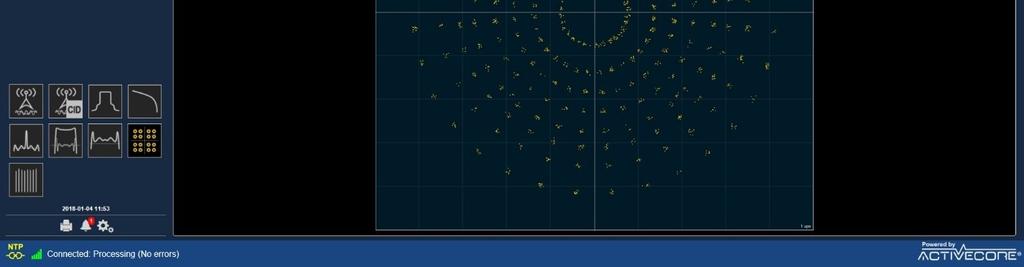
13 Figure 3. UI Main Page with Available Result and Navigation Controls: 1 The Receiver IP address; 2 Connection status; 3 Report Generation; 4 Active Alarms; 5 Control Panel; 6 Available Plots and Statistics 2 ; 7 - NTP Synchronization Status; 8 Plot Tools Figure 4. Login Page 2 Set of Available Plots and Statistics is standard dependable AVQ1022Rx-OM Rev 1.4 Page 13 of 54
 WEB page layout is presented in Figure 3.")
14 Figure 5. Network Settings WEB User Interface (UI) The WEB UI consists of screens conveniently representing the monitored signal parameters and plots. The Receiver Main (or default) WEB page layout is presented in Figure 3. Navigation between the UI pages is done by pressing icons from area 6, Figure 3, of the main window providing an intuitive interface to all parameters and settings of the receiver. In order to connect to the Receiver and call the UI, a user should enter the Receiver IP address to the WEB browser address bar. In order to set up parameters in the Control Panel and to eliminate unintentional changes (specifically helpful while using hand-held devices), any manual interaction via WEB UI requires confirmation by pressing Update button on the page. The confirmation window pops up every time a parameter has been changed or set. WEB GUI provides three levels of access to the Receiver: - "monitoring" level provides access to the Receiver basic monitoring functionality - reported statuses, numeric results and plots; in order to operate the receiver at this level, no password is required; - "operator" level provides an additional access to parameters which are responsible for alarm configuration and management through the device Control Panel; a default password for this level is "user"; - "administrator" level gives full control over the Receiver settings, alarm management functionality and remote upgrade are accessible; a default password is "admin". Both passwords can be changed from Administrator level through Control Panel -> System -> Access Settings. Please refer to on how to access the Control Panel. AVQ1022Rx-OM Rev 1.4 Page 14 of 54
15 3.1.3 Receiver Configuration The Receiver main functionality can be configured using Control Panel -> Configuration -> Settings page. The Settings page contains controls for setting-up the Receiver according to the expected signal central frequency, strength, reception conditions, etc. As an example, Figure 6 presents settings available for ATSC 3.0 standard. Most of the settings presented on this page are common to all broadcast standards supported by the Receiver. Figure 6. Receiver Settings. An Example for ASTC 3.0 For the full list of broadcast standard specific settings and their functional description, please refer to the correspondent section of this manual. Common for all broadcast standards settings are listed below. - Command sets the Receiver into Run or Idle (Stop command) state; it is advised to stop the Receiver before firmware or license file upgrades and switching between standards. - Active Input 3 defines which input of the Receiver is selected; - Rx gain, db defines the Receiver front-end gain or AGC mode; - Frequency, Hz sets signal central frequency; 3 Supported only by a Receiver with two inputs. AVQ1022Rx-OM Rev 1.4 Page 15 of 54


16 - Spectral Only ; only spectral parameters and plots are calculated and displayed; - Channel Mode defines channel estimation modes; it is recommended to use TX out mode when the Receiver samples signal directly from a transmitter system input or when there is no SFN/Multipath environment; use Off-Air option if working in SFN environment with multiple echoes. - Equalizer switches On/Off the Receiver internal equalizer; - Channel Filter switches On/Off the Receiver channel filter; the channel filter bandwidth is standard dependable; - Result Update Rate Reduction allows reducing the Receiver result update rate in proportion to the entered value; for example, setting n means that the results will be updated with n times reduced rate; this option allows reducing load to the network link between the Receiver and Host Defining a pre-set Emission mask Though the Receiver does spectral measurement based on a default emission mask defined in the correspondent broadcast standard, a user can change the pre-set emission mask points (see Figure 7). The emission mask required frequency offsets and attenuations along with the calculated Spectral output can be found in Emission section on Statistics page. Figure 7. Pre-set Emission Mask and Spectral Output The emission mask can be defined by a set of points with frequency offsets related to the central frequency and required attenuation. A point can be added or deleted. The defined emission mask is plotted in blue on Spectrum Plot. The following rules for defining the emission mask are applied: - maximum number of the points is limited to 10; - one point is always present. i.e. all points can not be deleted; AVQ1022Rx-OM Rev 1.4 Page 16 of 54
17 - a second point with equal to already present offset and attenuation values can not be added, i.e. no duplicates are allowed. Resolution bandwidth, used for calculation of the emission, is predefined and selected according to the broadcast standard requirements. If the Receiver supports multiple standards the user defined emission mask is reset to default upon changing the standard Alarm Management The Receiver alarm management is accessible through Control Panel -> Alarms path, see Figure 8. The management options provide a convenient way for enabling/disabling alarms, assigning actions undertaken in case of an alarm triggering, setting thresholds for the monitored parameters, maintaining alarm log, etc. Figure 8. Alarm Properties Available through the alarm management options are as following: a) alarm properties (Control Panel -> Alarms -> Alarm Properties), see Figure 8, where a user can individually enable or disable an alarm, assign to the alarm an action undertaken in the event of the alarm triggering, Alarm Set and Clear integration time and severity level. b) alarm Upper and Lower threshold settings (Control Panel -> Alarms -> Thresholds), see Figure 9, defining a parameter "safe" variation range. AVQ1022Rx-OM Rev 1.4 Page 17 of 54
18 Figure 9. Alarm Thresholds c) Alarm Log File Properties (Alarms -> Log Management), see Figure 10 two functional set of controls are related to the alarm log and parameter variation log files. The first set allows changing the Alarm Log display properties and clearing/resetting the log file. The second set controls Parameter Variation Log File allowing adjusting data storing periodicity and clearing/resetting the File. AVQ1022Rx-OM Rev 1.4 Page 18 of 54
 e-mail notification settings (Alarms -> Alarm")

19 Figure 10. Alarm and Variation Log Management d) notification settings (Alarms -> Alarm Settings), see Figure 11. Please, consult your network administrator for proper server settings. Figure 11. Alarm Settings e) alarm log and a list of currently active alarms (Alarms -> Alarm Log) AVQ1022Rx-OM Rev 1.4 Page 19 of 54

20 Figure 12. Alarm Log Downloading Variation Log and SNMP MIB Files Two files are available for downloading from the Receiver. They are Parameter Variation Log file containing time stamped records with measured values and SNMP MIB file. Figure 13. Downloadable Files below shows the files and access path to the downloading controls. The Receiver provides an automated log recording feature accessible through Alarms -> Log Management (see Figure 10). AVQ1022Rx-OM Rev 1.4 Page 20 of 54
21 Figure 13. Downloadable Files Parameter Variation Log records are created only while the Receiver's current command is RUN (3.1.3). The Log file is stored in the Receiver internal non-volatile memory as a comma separated text file (CSV). It is available for downloading from the Downloads menu (see Figure 13. Downloadable Files) Backup and Restore Receiver Settings The complete set of the Receiver current settings can be backed up and restored using a menu available from Control Panel -> System -> Settings Backup & Restore NMS and SNMP User Settings NMS settings are accessible through NMS Control Panel -> NMS -> Properties, see Figure 14. AVQ1022Rx-OM Rev 1.4 Page 21 of 54


22 Figure 14. NMS User Management Figure 15 below presents SNMP parameters which are available through Control Panel -> System -> SNMP. SNMP v.2 and v.3 are supported. Figure 15. SNMP Management AVQ1022Rx-OM Rev 1.4 Page 22 of 54
23 3.1.9 Setting Time The Receiver have two sources of time. Depending on user s application the Receiver can use its internal Real Time Clock engine or an external source with NTP capabilities. A preferred source can be selected from Control Panel -> System -> Set Time menu, see Figure 16. The selected source is used for time stamping of all events during the Receiver operation. Figure 16. Set Time The Receiver internal RTC can be manually set by entering new values in correspondent fields - Set year, Set month, etc. If NTP based synchronization is enabled, the Receiver will be trying to connect to NTP server every NTP synchronization interval. Current status of the NTP synchronization is reported in the Status line on the Receiver UI Main Page (Figure 3, 7) Resetting to Default Settings There are two ways to reset The Receiver settings to their defaults. The settings include all user defined parameters including the Receiver network configuration IP address, Gate Way and Mask. If the Receiver can be reached through Ethernet connection, i.e. it responds to its IP address and WEB UI is available, the most convenient way to reset the settings is to use Control Panel -> System -> Reset Settings to Default menu. AVQ1022Rx-OM Rev 1.4 Page 23 of 54
24 In the situation when there is no access to the unit through Ethernet (for example, if the Receiver IP address is lost or unknown) a hardware-based reset can be performed. For the hardware Reset pins 2 and 3 of the Relay DB9 connector (the unit rear panel) should be shortened for 10 seconds with the following power cycling of the unit. The hardware Reset step by step procedure is: - Power up the unit; - Wait for approximately 60 seconds until the unit fully booted; - Make short pins 2 and 3 of the Relay DB9 connector located on the unit rear panel; - Wait for 10 seconds; - Release the pins; - Power cycle the unit. The default settings are now in effect Remote Upgrade The Receiver can be remotely upgraded using Control Panel -> System -> Stored Files & Uploads menu. It is recommended to save the Receiver current settings (Figure 17) before upgrading the unit. Figure 17. Settings Backup and Restore The Receiver configuration can be restored at any time by uploading its previously stored settings. The Receiver remote upgrade procedure includes the following steps: 1. Navigate to the Stored Files & Uploads menu page (Figure 18). AVQ1022Rx-OM Rev 1.4 Page 24 of 54
. 3.")

25 Figure 18. Stored Files and Uploads 2. Click Browse to locate an upgrade image file (*.img). 3. Click Upload to initiate file transfer and system upgrade sequence. 4. Wait for the upgrade completion notification and a prompt to restart the unit (Figure 19). Figure 19. Upgrade Completion AVQ1022Rx-OM Rev 1.4 Page 25 of 54

26 Note: The first start-up of the unit after upgrade takes a bit longer since the upgrade image consistency is being verified. The system automatically rolls back to the previous image in case of any issues with the newly downloaded image are discovered. 3.2 Broadcast Standard Licensing The Receiver can be configured for supporting different broadcast standards. Though no additional software packages required for supporting the multi-standard functionality, a user can select only a standard(s) licensed to a particular unit. A list of the licensed standards is available through Control Panel -> System -> Licensed Standards menu (Figure 20). Selecting a licensed item from the list forces the Receiver switch to the selected standard. Figure 20. Licensed Standards License upgrade The number of supported by the Receiver standards can be changed by uploading a new license file generated by the Receiver manufacture. The upload procedure is very similar to the Receiver upgrade. The only difference is in the downloadable file which is avqlicense.lic in this case. The new license file is in effect after the Receiver reset. AVQ1022Rx-OM Rev 1.4 Page 26 of 54

27 3.3 WEB GUI Special Features Plot Common Tools A set of Tools available for a plot can be opened by Tools icon in the upper right corner of the plotting area. Please refer to Figure 3, item 8. The available set of tools might differ for different plots providing the most convenient way for working with a particular plot. There are two controls available from the Tools menu. The controls are Autoscale and Mode. By default, all plots use Autoscale. The plot is automatically scaled on X and Y axes in order to maximize the plotting area. In Autoscale no additional plot Modes can be selected. In order to access different Modes, the Autoscale control should be switched Off. Figure 21 below presents Modes Plot area tools when Autoscale is Off. Figure 21. Plot Common Tools and Modes - Normal mode can be used if no auto scaling is required; - Markers tool allows conveniently setting several markers on the plot, see Figure 22. Marker position can be individually adjusted using Edit icon in the Marker table. AVQ1022Rx-OM Rev 1.4 Page 27 of 54


28 Figure 22. Markers - Cross bar tool is useful for a quick relative measurement between any two points of the plot, see Figure 23. Figure 23. Cross Bar Tool - Manual Scale tool is a convenient way for adjusting Min/Max and Step (unit per division) values for a plot. See Figure 24. AVQ1022Rx-OM Rev 1.4 Page 28 of 54


29 Figure 24. Manual Scale Echo Profile Variation Range Tool Available for CIR/Echo Profile plot Variation Range tool allows setting windows defining a range of acceptable variations of each selected peak. The window size is defined by Echo Amplitude +/- Threshold, db and Echo time offset +/- Threshold, usec thresholds defined on Control Panel -> Alarms -> Thresholds page (Figure 9). Figure 25. CIR/Echo Plot Variation Range Tool AVQ1022Rx-OM Rev 1.4 Page 29 of 54
30 3.3.3 Report By pressing Report Icon on the Receiver WEB Main page (Figure 3, item 3) a "snapshot" report can be generated and stored on a local machine. The report contains all numerical data and plots and can be used for further analysis or troubleshooting. AVQ1022Rx-OM Rev 1.4 Page 30 of 54
31 4 Broadcast standard specifics 4.1 ATSC 1.0 (A/53 and A/153) A member of ActiveCore AVQ1022 product family, AVQ1022ATSC is an RF layer Monitoring Receiver and Signal Analyzer for A/53 and A/153 ATSC Digital Television Standards. Table below presents a list of available plots and monitored parameters. General Signal Parameters: General Spectral Parameters: ATSC A/53 and A/153 specific parameters: - Signal PAPR, db - Signal Power, dbm - Shoulder Attenuation, db (According to FCC requirements) - Bandwidth, MHz - Frequency Offset, Hz - Sampling Rate Shift, Hz - MER, db - EVM, % - SNR, db - Pilot amplitude error, db - Pilot phase error, degree - Amplitude (AM-AM), db and Phase (AM-PM) error, degree - Output signal Group Delay, micro seconds - Signal Inversion - Channel Emission Mask according to FCC requirements Available Plots: - Spectrum and in-band interference - Eye / Level Diagram - Non-Linear - HPA AM-AM, AM-PM - Group Delay, Frequency and Amplitude Response - CIR/Echo Profile Plot - CCDF Plot - Channel Frequency Response - Event History and Alarm log - History of Shoulder Attenuation / Group Delay/MER/SNR/PAPR variation - Transmitter SFN Drift Table 3. Monitored Parameters and Plots ATSC1.0 The list of monitored parameters, available plots and alarm events are constantly reviewed and extended. Please refer to the product data sheet for the most updated information ATSC 1.0 Settings Settings available for ATSC 1.0 standard is presented in Figure 26. ASTC 1.0 Settings. AVQ1022Rx-OM Rev 1.4 Page 31 of 54

32 Figure 26. ASTC 1.0 Settings There are two Measurement Modes in ATSC 1.0 standard Off Air and Tx Out. Off Air mode should be used for off-air measurements especially in presence of dynamic channel and/or strong echoes. Non-linear distortion measurements - Amplitude/Phase Errors and AM-AM/AM- PM plots - are not available in this mode. Tx Out mode should be used for when the Receiver samples signal directly at a transmitter output and non-linear distortions are to be numerically estimated SFN Drift Transmitter signal SFN Drift is measured as a shift of ATSC Data Field Sync over time. It is recommended using an external source of 1PPS signal for the drift precise measurements. SFN drift history and its instant value are presented in a graphical form on the SFN drift plot. Available on the plot "Set Reference Point" control allows setting the drift calculation start point. AVQ1022 alarm management system can be tuned to trigger an alarm event in case the drift exceeds a threshold. Please refer to Figure 9. For AVQ1022ATSC version of the receiver the threshold is hardcoded and set to +/- 15 nanoseconds as specified in A/153 part 2: ATSC Receiver Performance in the Presence of Echoes The Receiver performance and its ability to demodulate signal largely depends on the applied to the signal channel and presence of strong echoes that might exist at the Receiver input. For the echo removing and channel compensation, AVQ1022 uses a state-of-the-art equalizer which effectively increases the Receiver tolerance to the echoes and channel imperfections. Besides AVQ1022Rx-OM Rev 1.4 Page 32 of 54


33 other factors the equalizer performance depends on number of filter taps used in the equalizer, i.e. "equalizer length", that, in its turn, can affect processing time and the Receiver parameter update rate. Though the "longer" equalizer allows removing stronger echoes in a wider delay range, it is recommended setting "Equalizer" control On only when it is really necessary. The AVQ1022 ATSC Receiver implements an equalizer capable of removing pre- and post echoes in a wide range of amplitudes and delays. Table 4. Echo Cancelling Performance below defines the equalizer performance in terms of the echo level and time distance related to the main signal lobe. Echo relative amplitude, db Delay, microseconds, Echo canceller Off / On -15 ±4 / ±11.8 > ±1.86 / ±5.6 > ±0.6 / ±2.04 > Table 4. Echo Cancelling Performance Remaining echo relative amplitude, db ATSC 1.0 Statistics and Plots Figure 27. ATSC 1.0 Signal Statistics AVQ1022Rx-OM Rev 1.4 Page 33 of 54


34 Figure 28. ATSC 1.0 Eye Diagram Figure 29. ATSC 1.0 Constellation Diagrams AVQ1022Rx-OM Rev 1.4 Page 34 of 54
35 4.2 ATSC 3.0 (A/322) A member of ActiveCore AVQ1022 product family, AVQ1022ATSC30 is an RF layer Monitoring Receiver and Signal Analyzer for A/322 ATSC 3.0 Digital Television Standard. Table below presents a list of available plots and monitored parameters. General Signal Parameters: General Spectral Parameters: ATSC 3.0 specific parameters: - Signal PAPR, db - Signal Power, dbm - Shoulder Attenuation, db (According to FCC requirements) - Bandwidth, MHz - Frequency Offset, Hz - Sampling Rate Shift, Hz - Bootstrap, L1B, L1D MERs, db - Selected for processing PLP raw and final MER 4, db - System MER, db 5 - Number of LDPC iterations per FEC block for L1B/D parts of ASTC 3.0 frame and selected PLP - L1B, L1D and selected PLP BER before LDPC decoding - L1B, L1D parity check results - List of detected TxIDs with their time offsets - List of available PLPs - Detailed Bootstrap, L1B and L1B information - LLS info 6 - Output signal Group Delay, micro seconds - Signal Inversion - Channel Bandwidth and Emission Mask according to FCC requirements Available Plots: - Spectrum and in-band interference - Channel Group Delay, Frequency and Amplitude Response - CIR/Echo Profile Plot - CCDF Plot - Bootstrap, L1B and L1D constellations - Selected PLP constellation - Event History and Alarm log - History of Shoulder Attenuation / Group Delay/MER variation - Transmitter SFN Drift Table 5. Monitored Parameters and Plots ATSC3.0 4 Two MER estimations are available raw and final; PLP raw (total) MER might be affected by LDM layer. A final MER is calculated after LDM subtracted. details 5 System MER is calculated as an average of Bootstrap, L1B/D and selected PLP MERs 6 There are some limitations on LLS info availability; please contact Avateq Corp. technical support for AVQ1022Rx-OM Rev 1.4 Page 35 of 54


36 4.2.1 SFN Drift Transmitter signal SFN Drift is measured as a shift of ATSC 3.0 Bootstrap over time. It is recommended using an external source of 1PPS signal for the drift precise measurements. SFN drift history and its instant value are presented in a graphical form on the SFN drift plot. Available on the plot "Set Reference Point" control allows setting the drift calculation start point. AVQ1022 alarm management system can be tuned to trigger an alarm event in case the drift exceeds +/- GI ATSC 3.0 Statistics and Plots Below are examples of available ATSC 3.0 signal data and statistics presented in numerical format. AVQ1022Rx-OM Rev 1.4 Page 36 of 54
37 Figure 30. ATSC 3.0 Statistics A user can select a PLP to be monitored (MER, BER) and plotted by clicking on Select option from the PLPs in System table ( Figure 30). AVQ1022ATSC30 provides convenient tools for detailed analysis of ATSC 3.0 signaling info. The signaling info is available in a raw format as presented and decoded in the Bootstrap and L1B/D parts of the frame, please refer to Figure 31 below. AVQ1022Rx-OM Rev 1.4 Page 37 of 54
: - Off-Air SFN mode is recommended")

38 Figure 31. ATSC 3.0 Signaling Channel Estimation Modes AVQ1022ATSC30 allows performing channel estimation in two distinctive modes (Figure 32): - Off-Air SFN mode is recommended mode for multipath environment that is a typical application for SFN and in-field measurements; - Tx Output is the preferable mode for channel estimation mode in application where no multipath echoes or SFN transmission are expected. It is also recommended to use this mode for measurements performed directly at a transmitter system output including a band-pass filter response. AVQ1022Rx-OM Rev 1.4 Page 38 of 54
39 Figure 32. ATSC 3.0 Channel Estimation Modes 4.3 DTMB (GB ) A member of ActiveCore AVQ1020 product family, AVQ1020DTMB is an RF layer Monitoring Receiver and Signal Analyzer for GB compliant Digital Television Terrestrial Broadcasting System. Table below presents a list of available plots and monitored parameters. General Signal Parameters: General Spectral Parameters: - Signal PAPR, db - Input signal power, dbm - Shoulder Attenuation, db (GB requirements) - Bandwidth, MHz - Frequency Offset, Hz - Sampling Rate Shift, Hz DTMB specific: - MER, db - Amplitude (AM-AM), db and Phase (AM-PM) error, degree - Output signal Group Delay, micro seconds - Signal Inversion - Channel Mask according to GB requirements - PN and Guard Interval length - DTMB mode: Single or Multi carrier AVQ1022Rx-OM Rev 1.4 Page 39 of 54
40 Available Plots: - Spectrum - Constellation - MER variation from symbol to symbol - Non-Linear - HPA AM-AM, AM-PM curves - Group Delay, Frequency and Amplitude Response - Echo Profile Plot - CCDF Plot - Channel Frequency Response - Event History and Alarm log - History of Shoulder Attenuation / Group Delay/MER/SNR/PAPR variation - Transmitter SFN Drift Table 6. Monitored Parameters and Plots DTMB DTMB Receiver Settings Figure 33 below presents settings available when the Receiver is operating in DTMB standard. Most of the setting are common to all supported standards. Figure 33. DTMB Specific Settings DTMB specific settings include: - Bandwidth selects bandwidth of the expected signal; allows selection of 8, 7 or 6 MHz bandwidth; AVQ1022Rx-OM Rev 1.4 Page 40 of 54
41 4.3.2 SFN Drift Transmitter signal SFN Drift is measured as a shift of DTMB frame over time. It is recommended using an external source of 1PPS signal for the drift precise measurements. SFN drift history and its instant value are presented in a graphical form on the SFN drift plot. Available on the plot "Set Reference Point" control allows setting the drift calculation start point. AVQ1022 alarm management system can be tuned to trigger an alarm event in case the drift exceeds a threshold. For AVQ1022DTMB the threshold is hardcoded and set to ±GI length DTMB Receiver Performance in the Presence of Echoes The Receiver performance and its ability to demodulate signal largely depends on the applied to the signal channel and presence of strong echoes that might exist at the Receiver input. For the echo removing and channel compensation, AVQ1022 uses a state-of-the-art equalizer which effectively increases the Receiver tolerance to the echoes and channel imperfections. Besides other factors the equalizer performance depends on number of filter taps used in the equalizer, i.e. "equalizer length", that, in its turn, can affect processing time and the Receiver parameter update rate. Though the "longer" equalizer allows removing stronger echoes in a wider delay range, it is recommended setting "Equalizer" control On only when it is really necessary. The AVQ1022DTMB Receiver implements an equalizer capable of removing pre- and post echoes in a wide range of amplitudes and delays. Table 4 below defines the equalizer performance in terms of the echo level and time distance related to the main signal lobe. Echo relative amplitude, db Delay, microseconds, Echo canceller Off / On <-20 ±3.00 / ±50.0 < ±2.76 / ±13.3 < ±1.33 / ±6.67 < ±0.53 / ±2.65 < Table 7. Echo Cancelling Performance Remaining echo relative amplitude, db DTMB Statistics Figure 34 below presents DTMB signal statistics and available numerical data. Please refer to the common to all broadcast standards sections of the Manual for the full set of plots and data provided by AVQ1022 Receiver. AVQ1022Rx-OM Rev 1.4 Page 41 of 54

, db and Phase (AM-PM) error, degree - Output signal Group Delay,")
42 Figure 34. DTMB Statistics 4.4 DAB/DAB+/T-DMB A member of ActiveCore AVQ1020 product family, AVQ1020DAB is an RF layer Monitoring Receiver and Signal Analyzer for DAB/DAB+/T-DMB standards. Table below presents a list of available plots and monitored parameters. General Signal Parameters: General Spectral Parameters: DAB/DAB+/T-DMB specific parameters: - Signal PAPR, db - Input signal power, dbm - Shoulder Attenuation, db - Bandwidth, MHz - Frequency Offset, Hz - Sampling Rate Shift, Hz - MER, db - DAB Mode - DAB Modulation - FFT Size - Signal Inversion - Guard Interval - Amplitude (AM-AM), db and Phase (AM-PM) error, degree - Output signal Group Delay, micro seconds - FIC FIB errors and BER before Viterby - Ensemble and MSC info - TII list with time offsets - Channel Mask at predefined offsets according to ETSI EN Available Plots: - Spectrum AVQ1022Rx-OM Rev 1.4 Page 42 of 54
43 - Constellation Diagram - Symbol MER Diagram - Non-Linear - HPA AM-AM, AM-PM curves - Group Delay, Frequency and Amplitude Response - Echo profile Plot - CCDF Plot - Channel Frequency Response - Event History and Alarm Log - Parameter log - Transmitter SFN Drift Table 8. Monitored Parameters and Plots DAB/DAB+/T-DMB DAB/DAB+/T-DMB Receiver settings Figure 35 below presents settings available when the Receiver is operating in DAB/DAB+/T- DMB standard. Figure 35. DAB Receiver Settings SFN Sync SFN Sync option activates AVQ1022DAB functionality allowing to synchronize (to bind) the SFN Echo profile pattern with the unit internal clocks. Once synchronized the pattern (Echo) peaks are displayed in the order regardless of the main signal, i.e. the signal from Main AVQ1022Rx-OM Rev 1.4 Page 43 of 54
44 transmitter, position or amplitude changes. The sync allows to adjust and monitor delays from different transmitters in SFN networks. Current SFN Sync status is reported on the unit Control->Status page, section Reference and timing, see Figure 36 below. Figure 36. DAB SFN Pattern Sync SFN Drift Transmitter signal SFN Drift is measured as a variation of NULL symbol appearance at the transmitter system output of each transmission frame over time. It is recommended using an external source of 1PPS signal for the drift precise measurements. SFN drift history and its instant value are presented in a graphical form. Available on the plot "Set Reference Point" control allows setting the drift calculation start point. AVQ1022 alarm management system can be tuned to trigger an alarm event in case the drift exceeds a threshold. For AVQ1022DAB version of the receiver the threshold is hardcoded and set to +/- GI/2 duration of the correspondent DAB mode DAB/DAB+ Streaming Modes AVQ1022DAB supports two streaming modes: - streaming an audio service to be listened in real-time mode on Host; - streaming a service into a file; the file can be stored on Host and played back later. The streaming modes can be selected from Mode drop-down menu on AVQ1022 Control Panel->Configuration->Settings page, Figure 37. AVQ1022Rx-OM Rev 1.4 Page 44 of 54
45 Figure 37. DAB/DAB+ Streaming Options Below is a step-by-step procedure of setting up AVQ1022 for a streaming mode. The described steps are common for all supported streaming modes. 1. Tune AVQ1022DAB to a desired frequency (DAB channel) and check that the unit can demodulate and decode the signal, for example, by checking Ensemble and MSC info section on Statistic page of the unit UI (Figure 38). AVQ1022Rx-OM Rev 1.4 Page 45 of 54

46 Figure 38. DAB/DAB+ Ensemble and MSC Info 2. Select a desired Streaming option from the drop-down Mode menu on Control Panel->Configuration->Settings page (Figure 37). 3. Open DAB MUX page (Figure 39) by clicking on Stream icon. AVQ1022Rx-OM Rev 1.4 Page 46 of 54

47 Figure 39. DAB/DAB+ MUX and Service Selection 4. A desired service can be selected/unselected by pressing select/stop button in the correspondent line. Next steps are different and depend on the Streaming mode option Streaming an Audio Service Streaming an audio service functionality is switched On by selecting Stream Audio option from the Mode menu. It is assumed that there is VLC Media Player version installed on Host machine. The required version can be downloaded from 1. Run VLC Player 2. Select Media->Open Network Stream to call Open Media dialog (Figure 40). AVQ1022Rx-OM Rev 1.4 Page 47 of 54

48 Figure 40. VLC Media Player 3. Enter connection URL - the unit IP address followed by 8080 port number and /dabaudio in to Open Media dialog form (Figure 41). For example, for a unit with IP the required network URL is The required URL is presented on the DAB Stream page for your convenience. Please see Connect at string in Figure 39. AVQ1022Rx-OM Rev 1.4 Page 48 of 54

49 Figure 41. VLC Open Media Dialog 4. Click Play on the VLC Open Media page. Note: Avateq recommends using VLC Media Player ver Streaming a Service into File Streaming a service into file functionality is switched On by selecting Download audio file option from the Mode menu. 1. Open a new page in your WEB browser; in URL locator of the WEB page enter the same URL as for VLC Media Player. Please see step 5 description from Check that a file with selected service will start recording you should see dabaudio.mp2(4) (the default file name can not be changed) and number of recorded Mbytes. 3. In order to stop the recording, press Stop for the service on DAB Stream page. It is important to Stop the streaming of the service before closing the WEB page. AVQ1022Rx-OM Rev 1.4 Page 49 of 54
50 Notes: 1. Avateq strongly recommends using Chrome WEB browser for recording a service in to a file. Possible errors which might occur in Downloading audio file mode are: Not Found: the unit is not in Streaming mode, i.e. Stream Off option is selected in the Mode settings. - HTTP ERROR 503: no service is selected for streaming. 4.5 DVB-S/S2/2x and DVB-CID A member of ActiveCore AVQ1022 product family, AVQ1020DVBS is an RF layer Monitoring Receiver and Signal Analyzer for EN , ETSI EN , ETSI EN and ETSI TS DVB-S/S2/S2x and DVB-CID Standards. Table below presents a list of available plots and monitored parameters. General Signal Parameters: General Spectral Parameters: DVB-S/S2 specific parameters: - Signal PAR, db - Input signal power, dbm - Shoulder Attenuation, db; - Bandwidth, MHz - Frequency Offset, Hz; - MER, db - EVM, % - SNR, db - STED, STEM - Eb / No - Signal Inversion - Signal Format DVB-S/S2/S2x - DVB-CID presence and decoding - Constellation and ModCod - FEC frame format, according to ETSI EN DVB-S2/S2x pilots presence - Spectrum mask Available Plots: - Spectrum - In-band interference spectrum 7 - Constellation - Echo Profile Plot - Signal CCDF Plot - Decoded DVB-CID info - MER variation - Event History and Alarm Log - History of Shoulder Attenuation/ MER/PAR variation 7 For DVB-S2 only AVQ1022Rx-OM Rev 1.4 Page 50 of 54
51 Table 9. Monitored Parameters and Plots DVB-S/S2/S2X and DVB-CID DVB-S/S2/S2x Receiver Settings Table below presents settings available when the Receiver is operating in DVB-S/S2 mode. Figure 42. DVB-S/S2/S2x Receiver Settings DVB-S/S2/S2x mode specific settings include: - Symbol Rate allows specifying DVB-S/S2/S2x signal Symbol Rate; - Roll Off Factor is used to set Roll Off Factor; - "DVB-CID decode On/Off" switches On/Off DVB-CID decoding functionality DVB-S/S2 Statistics and Plots Below only specific to DVB-S/S2/2x broadcast standard plots and available numerical data are presented. Please refer to the common to all broadcast standards sections of the Manual for the full set of plots and data provided by AVQ1022 Receiver. AVQ1022Rx-OM Rev 1.4 Page 51 of 54


52 Figure 43. DVB-S/S2/S2x Spectrum with In-band DVB-CID Signal Figure 44. Signal General and DVB-S/S2 Specific Statistics AVQ1022Rx-OM Rev 1.4 Page 52 of 54


53 Figure 45. DVB-CID Info Figure 46. DVB-S2x Constellation AVQ1022Rx-OM Rev 1.4 Page 53 of 54
Signal Analyzers and Transmitter System Calibration Products
 ActiveCore Engineering Products Signal Analyzers and Transmitter System Calibration Products Made in Canada AVATEQ CORP. AVATEQ CORP. About The Company Established in 2009 by experts in broadcasting engineering,
120W UHF Transmitter/Repeater
 Product Features 470 MHz - 860 MHz Broadband Transmitter/Repeater LDMOS Power Amplifier provides 120 Watt output for ATSC, ATSC-M/H, CMMB, DTMB, DVB-T/H, DVB-T2, DVB-SH, ISDB-T/TB,, DAB, DAB+ and T-DMB
Maxiva TM VAX Compact
 Maxiva TM VAX Compact Low Power VHF Band III TV/DAB Transmitter / Transposer / Gap Filler The Maxiva VAX Compact family of VHF Band III solid-state transmitters, transposers/translators and gap fillers
Maxiva UAXT Ultra-Compact/ VAXT Ultra-Compact Low Power UHF/VHF Transmitter / Transposer / Gap Filler
 Maxiva UAXT Ultra-Compact/ VAXT Ultra-Compact Low Power UHF/VHF Transmitter / Transposer / Gap Filler The new Maxiva UAXT & VAXT Ultra Compact family of UHF & VHF solid-state Transmitters, Transposers
Digital Audio Broadcasting Eureka-147. Minimum Requirements for Terrestrial DAB Transmitters
 Digital Audio Broadcasting Eureka-147 Minimum Requirements for Terrestrial DAB Transmitters Prepared by WorldDAB September 2001 - 2 - TABLE OF CONTENTS 1 Scope...3 2 Minimum Functionality...3 2.1 Digital
DVB-T/H Portable Test Transmitter
 Product Features Portable Design Durable Enclosure L-Band RF Output Full hierarchical mode support SFN and MFN support Near seamless switching between inputs Superior MER performance Outstanding Linear
IZT T1000 Compact Broadcast Modulator
 www.izt-labs.de IZT T1000 Compact Broadcast Modulator Fully reconfigurable, software-defined modulator platform for DAB and DVB-T/DVB-T2 VHF and UHF (selectable frequency from 30 MHz to 860 MHz in steps
Channel processing equipment
 Channel processing equipment 1. Product description DVB-T/T2 to DVB-C transmodulator is a 4 channel DVB-T/T2 to DVB-C transmodulator (in text - module). The module uses transparent transmodulation - passing
PerMIT. A complete broadcast measurement and analysis solution
 Enkom Inventis is presenting a high-performance solution to analyse your broadcast networks. The new Performance Measurement & Investigation Tool for Digital Broadcasting (PerMIT) is a powerful tool and
June 09, 2014 Document Version: 1.1.0
 DVB-T2 Analysis Toolkit Data Sheet An ideal solution for SFN network planning, optimization, maintenance and Broadcast Equipment Testing June 09, 2014 Document Version: 1.1.0 Contents 1. Overview... 3
Layered Division Multiplexing (LDM) Summary
 Summary") Layered Division Multiplexing (LDM) Summary 1 2 Layered Division Multiplexing LDM super-imposes multiple physical layer data streams with different power levels, channel coding and modulation schemes for
Layered Division Multiplexing (LDM) Summary 1 2 Layered Division Multiplexing LDM super-imposes multiple physical layer data streams with different power levels, channel coding and modulation schemes for
A Novel On-Channel Repeater for Terrestrial-Digital Multimedia Broadcasting System of Korea
 A Novel On-Channel Repeater for Terrestrial-Digital Multimedia Broadcasting System of Korea Sung Ik Park, Heung Mook Kim, So Ra Park, Yong-Tae Lee, and Jong Soo Lim Broadcasting Research Group Electronics
PRODUCT CATALOGUE: March 2018
 PRODUCT CATALOGUE: March 2018 KVARTA SOFT LTD, Bulgaria, Veliko Tarnovo, Tzar Kaloyan 13, ZIP Code: 5000, E-mail: sales@kvarta.net, Website: 1 DVB MONITOR A/C/T The DVB Monitor is specially built for CATV
Outdoor Terrestrial Transmitter / Repeater
 Product Features Compact, outdoor, self-contained unit Environmentally protected light-weight cabinet Thermal electric and forced air cooling system with easily replaceable air filter Internal heater Front
Getting Started Guide
 MaxEye Digital Audio and Video Signal Generation ISDB-T Signal Generation Toolkit Version 2.0.0 Getting Started Guide Contents 1 Introduction... 3 2 Installed File Location... 3 2.1 Soft Front Panel...
FM TRANSMITTER 5kW-10kW
 BLUE SERIES TOUCH SCREEN FM TRANSMITTER 5kW-10kW LATEST HIGH EFFICIENCY TECHNOLOGY Blue Series Technical Data The new Blue FM Transmitters Series sets ultimate features by the evolution of RF technologies.
R40 Mk III AIS Base Station
 R40 Mk III AIS Base Station The new R40 Mk III AIS Base Station from Saab TransponderTech is a result of our on-going efforts to enhance all our products. The R40 Mk III is equipped with a new Base Station
AirScope Spectrum Analyzer User s Manual
 AirScope Spectrum Analyzer Manual Revision 1.0 October 2017 ESTeem Industrial Wireless Solutions Author: Date: Name: Eric P. Marske Title: Product Manager Approved by: Date: Name: Michael Eller Title:
WPE 48N USER MANUAL Version1.1
 Version1.1 Security instructions 1. Read this manual carefully. 2. Follow all instructions and warnings. 3. Only use accessories specified by WORK PRO. 4. Follow the safety instructions of your country.
MEX II. Multimode TV Exciter HE ANALOG / DIGITAL
 ANALOG / DIGITAL Multimode TV Exciter Fully numerical signal elaboration and modulation Adaptive pre-distorter and pre-equalizer Multi-Standard equipment Dual Cast transmitter Band I Band III Band IV/V
REV Product Catalogue
 REV 14 2014 Product Catalogue Company Introduction is a privately owned and operated company with our head of- Unique Broadband Systems has been in business since 1990 as Unique Broadband Systems, Inc.
SFT DAB. DAB Transmitters up to 15 kw rms.
 SFT DAB Series DAB Transmitters up to 15 kw rms www.screen.it Screen is a world-renowned company focused on turn-key and end-to-end solutions for all broadcasting needs. With more than 28 years of experience,
MultiMaster. Base Station Test Tools. Multi Purpose Base Station Tester. Introduction. Feature
 Introduction The GenComm is a comprehensive and cost effective solution for performing base station and repeater maintenance in any environment covering all CDMA Standards including cdmaone, cdma2000 1x
DTVM 2000(T) Digital Terrestrial Television Transmitter Monitor
 Digital Terrestrial Television Transmitter Monitor") DTVM 2000(T) Digital Terrestrial Television Transmitter Monitor The DTVM 2000(T) Digital Terrestrial Television Transmitter Monitor range has been designed for DVB signal quality measurement applications.
DTVM 2000(T) Digital Terrestrial Television Transmitter Monitor The DTVM 2000(T) Digital Terrestrial Television Transmitter Monitor range has been designed for DVB signal quality measurement applications.
"Terminal RG-1000" Customer Programming Software. User Guide. August 2016 R4.3
 "Terminal RG-1000" Customer Programming Software User Guide August 2016 R4.3 Table of Contents Table of Contents Introduction 2 3 1.1 Software installation 3 1.2 Connecting the RG-1000 GATEWAYs to the
Kodiak Corporate Administration Tool
 AT&T Business Mobility Kodiak Corporate Administration Tool User Guide Release 8.3 Table of Contents Introduction and Key Features 2 Getting Started 2 Navigate the Corporate Administration Tool 2 Manage
8800SX TETRA Base Station Operation
 8800SX TETRA Base Station Operation 8800SX TETRA Base Station Test The 8800SX TETRA Base Station Test option utilizes the ETSI standard defined TETRA T1 test mode. - ETSI is the European Telecommunications
DAB+ Voice Break-In Solution
 Product Brief DAB+ Voice Break-In Solution The Voice Break-In (VBI) solution is a highly integrated, hardware based repeater and content replacement system for DAB/DAB+. VBI s are in-tunnel/in-building
GPSR116 Quick Start Guide
 GPSR116 Quick Start Guide .21 [ 5,3] [482,6] 18.12 [460,3] GPSR116 Quick Start Guide Rev 2.35 [8,9] Introduction Microlab s digital GPS repeater system can be used for cellular communications UTC synchronization
SIGNAL PROCESSING WIRELESS COMMUNICATION RF TEST AND MEASUREMENT AUTOMOTIVE DEFENSE AND AEROSPACE
 SIGNAL PROCESSING WIRELESS COMMUNICATION RF TEST AND MEASUREMENT AUTOMOTIVE DEFENSE AND AEROSPACE Your One-Stop Provider for In-Vehicle Infotainment (IVI Test), Set-Top-Box, Digital TV Mobile TV test solution.
TCG 02-G FULL FEATURED SATELLITE CLOCK KEY FEATURES SUPPORTS
 FULL FEATURED SATELLITE CLOCK TCG 02-G The TCG 02-G is a highly accurate, full featured GPS and GLONASS (GNSS) clock. Offering multiple oscillator options, Time Code and Frequency outputs, it fits virtually
PT 5879 MIP INSERTER AGS*/MIP. ransmitter. TRX ID TAG data. TRX ID TAG data. TRX ID TAG data. TRX ID TAG data. data Reset Count Timing
 PT 5879 MIP INSERTER *supports pro any existing Carousel management ransmitter 1 PPS 10 MHz AGS*/MIP G-2 TS. MIP 0 0 0 0 0 0 0 0 control DVB-T Modulation (SFN) DVB Chan I NTRODUCTION The Single Frequency
WEB I/O. Wireless On/Off Control USER MANUAL
 Wireless On/Off Control Technical Support: Email: support@encomwireless.com Toll Free: 1 800 617 3487 Worldwide: (403) 230 1122 Fax: (403) 276 9575 Web: www.encomwireless.com Warnings and Precautions Warnings
HIGH POWER LIQUID COOLED SOLID STATE UHF TV TRANSMITTER
 MAGMA SERIES PRODUCT CATALOG HIGH POWER LIQUID COOLED SOLID STATE UHF TV TRANSMITTER BROADBAND 25KW IN A SINGLE CABINET REDUNDANT HOT SWAPPABLE POWER SUPPLIES The Magma Series Forging a New Path Introduction
Model OT-1000-HH 1GHz SuperMod Optical Transmitter, DWDM ADVANCED OPERATING MANUAL
 Model OT-1000-HH 1GHz SuperMod Optical Transmitter, DWDM ADVANCED OPERATING MANUAL The features mentioned in this Advanced OT-1000-HH Manual can be accessed only with the optional OT-NEC-A, Network Element
TCG 02-G FULL FEATURED SATELLITE CLOCK KEY FEATURES SUPPORTS
 FULL FEATURED SATELLITE CLOCK TCG 02-G The TCG 02-G is a highly accurate, full featured GPS and GLONASS (GNSS) clock. Offering multiple oscillator options, Time Code and Frequency outputs, it fits virtually
GFT Channel Digital Delay Generator
 Features 20 independent delay Channels 100 ps resolution 25 ps rms jitter 10 second range Output pulse up to 6 V/50 Ω Independent trigger for every channel Four triggers Three are repetitive from three
TC-2300B DAB/DMB Tester
 TC-2300B DAB/DMB Tester Product Information TC-2300B DAB/DMB Tester supports the Eureka-147 (ESTI EN 301 500) system, freely changes every parameter related to protocols in a GUI operating system and simultaneously
Keysight X-Series Signal Analyzers
 Keysight X-Series Signal Analyzers This manual provides documentation for the following Analyzers: PXA Signal Analyzer N9030A EXA Signal Analyzer N9010A MXA Signal Analyzer N9020A CXA Signal Analyzer N9000A
PROWATCHNeo. PROWATCHNeo monitoring system WEB SERVER CONTROL HEVC H K SNMP COMPATIBLE. High Effciency Video Codec
 monitoring system PROWATCHNeo SNMP COMPATIBLE Easily scalable WEB SERVER CONTROL Total flexibility HEVC H.265 High Effciency Video Codec 4 K High Definition PROWATCHNeo monitoring system Remote monitoring
RIZ DRM Compact Solution
 The RIZ DRM Compact Solution offers total solution in digitalization of AM broadcasting. It is applicable not only at the new generation of digital ready transmitters but also to the existing analogue
External Source Control
 External Source Control X-Series Signal Analyzers Option ESC DEMO GUIDE Introduction External source control for X-Series signal analyzers (Option ESC) allows the Keysight PXA, MXA, EXA, and CXA to control
Purchase of DAB+ transmitters
 TECHNICAL REQUIREMENTS AND SPECIFICATIONS FOR PUBLIC TENDER No. JN-B0735 Purchase of DAB+ transmitters 1 INTRODUCTION... 4 2 GENERAL... 5 2.1 CE AND EMC... 5 2.2 INSTRUCTIONS FOR OPERATION AND MAINTENANCE...
VENTUS 1.0 All in One USB Type of DTV / Mobile TV Signal Generator
 to be Better or to be Different LUMANTEK VENTUS 10 All in One USB Type of DTV / Mobile TV Signal Generator ATSC-Mobile CMMB DTMB DVB-T/H DVB-C OpenCable ATSC T-DMB / DAB+ ISDB-T Mobility + Upgradable Design
A30 FM/DAB Monitoring Decoder
 A30 FM/DAB Monitoring Decoder Professional, flexible FM/DAB Monitoring and Measurement Receiver Backup- and Rebroadcast-Receiver RF capabilities Dual FM tuner, DAB+ tuner, 3 RF antenna inputs Large-signal
APX Mobile and Portable Automated Test and Alignment
 APX Mobile and Portable Automated Test and Alignment Software Updates First things first! Be sure to check that you are running the latest software versions for the 8800SX and its applications. Visit the
ExpoM - ELF User Manual
 ExpoM - ELF User Manual Version 1.4 ExpoM - ELF User Manual Contents 1 Description... 4 2 Case and Interfaces... 4 2.1 Overview... 4 2.2 Multi-color LED... 5 3 Using ExpoM - ELF... 6 3.1 Starting a Measurement...
Working Party 5B DRAFT NEW RECOMMENDATION ITU-R M.[500KHZ]
![Working Party 5B DRAFT NEW RECOMMENDATION ITU-R M.[500KHZ]](/thumbs/92/109768647.jpg "Working Party 5B DRAFT NEW RECOMMENDATION ITU-R M.[500KHZ]") Radiocommunication Study Groups Source: Subject: Document 5B/TEMP/376 Draft new Recommendation ITU-R M.[500kHz] Document 17 November 2011 English only Working Party 5B DRAFT NEW RECOMMENDATION ITU-R M.[500KHZ]
Radiocommunication Study Groups Source: Subject: Document 5B/TEMP/376 Draft new Recommendation ITU-R M.[500kHz] Document 17 November 2011 English only Working Party 5B DRAFT NEW RECOMMENDATION ITU-R M.[500KHZ]
DTA-2115 All-Standard, All-Band Modulator
 DTA-2115 Dystrybucja: elmier.pl All-Standard, All-Band Modulator DATASHEET Feb 2015 elmier@elmier.pl +48 500 167 343 Table of Contents 1. Introduction... 3 General Description... 3 Block Diagram... 3 Software
PC Tune PC Tune Test Procedures for 5100 Series Portable Radios
 PC Tune PC Tune Test Procedures for 5100 Series Portable Radios Part Number 002-9998-6513014 August 2008 Copyright 2006, 2007, 2008 by EFJohnson Technologies The EFJohnson Technologies logo, PC Configure,
TC-2300B DAB/DMB Tester
 www.tescom.co.kr DAB/DMB Tester Realtime Ensemble Mux (Unlimited Pattern Generation) OFDM Modulator RF Up-Converter Support Eureka-147(ETSI EN 301 400) protocol Combination test equipment (OFDM modulator
WE TAKE CARE OF YOUR AUDIO. DAB+ SOLUTIONS
 WE TAKE CARE OF YOUR AUDIO. DAB+ SOLUTIONS INTRO s DAB+ product range enables broadcasters to use existing legacy as well as IP-capable transmitters at the same time. Serving of IP accessible and inaccessible
LinkAlign-60RPT Set-up and Operation Manual
 LinkAlign-60RPT Set-up and Operation Manual LinkAlign Setup and Operation Proprietary, Nextmove Technologies Page 1 LinkAlign Setup and Operation Proprietary, Nextmove Technologies Page 2 Description of
8800SX DMR Repeater Test Option 06
 8800SX DMR Repeater Test Option 06 DMR Repeater Test Option The DMR Repeater test option allows testing of a DMR Repeater that is in conventional DMR Mode. Trunking or analog configurations are not supported.
SAPLING WIRELESS SYSTEM
 SAPLING WIRELESS SYSTEM Sapling Wireless System DESCRIPTION A Wireless Clock System starts with a master clock with a transmitter. The master clock s transmitter transmits the time data to the secondary
TC-2300B DAB/DMB Tester
 TC-2300B DAB/DMB Tester Product Information TC-2300B DAB/DMB Tester supports the Eureka-147 (ESTI EN 301 500) system, freely changes every parameter related to protocols in a GUI operating system and simultaneously
DragonLink Advanced Transmitter
 DragonLink Advanced Transmitter A quick introduction - to a new a world of possibilities October 29, 2015 Written by Dennis Frie Contents 1 Disclaimer and notes for early release 3 2 Introduction 4 3 The
Quick Start Guide. RSP-Z2 Dual Channel Analog-IP Interface
 INTEROPERABILITY NOW Quick Start Guide RSP-Z2 Dual Channel Analog-IP Interface Designed and Manufactured by: JPS Interoperability Solutions 5800 Departure Drive Raleigh, NC 27616 919-790-1011 Email: sales@jpsinterop.com
Global Navigation Satellite System for IE 5000
 Global Navigation Satellite System for IE 5000 Configuring GNSS 2 Information About GNSS 2 Guidelines and Limitations 4 Default Settings 4 Configuring GNSS 5 Configuring GNSS as Time Source for PTP 6 Verifying
PXI LTE/LTE-A Downlink (FDD and TDD) Measurement Suite Data Sheet
 Measurement Suite Data Sheet") PXI LTE/LTE-A Downlink (FDD and TDD) Measurement Suite Data Sheet The most important thing we build is trust Designed for the production test of the base station RF, tailored for the evolving small cell
PXI LTE/LTE-A Downlink (FDD and TDD) Measurement Suite Data Sheet The most important thing we build is trust Designed for the production test of the base station RF, tailored for the evolving small cell
1 UAT Test Procedure and Report
 1 UAT Test Procedure and Report These tests are performed to ensure that the UAT Transmitter will comply with the equipment performance tests during and subsequent to all normal standard operating conditions
Quick Start Instructions EMV-INspektor V2
 Connecting the : The illustration below shows the connection diagram for the. Step 1: Before connecting the to the voltage supply, first establish the connection of the to the measuring clamp adapters.
WEIVER GHz 70 W. 7 Kg. Frequency. Cigar Power. Weight. AM radio to Satellite & GPS. Weights Max 65% less than other brand s capture systems
 WEIVER 2.0 LUMANTEK Catalogue No.31 /2013 FM / AM / RDS / DVB-T/T2 / DVB-S/S2 / DVB-C / DAB / DAB+ / ATSC / ATSC-MDTV / NTSC / CMMB / QAM-B / ATV / ISDB-T / DTMB / T-DMB / CDMA / PAL / UMTS / Wifi / WiMax
ATSC 3.0 Physical Layer Overview
 ATSC 3.0 Physical Layer Overview Agenda Terminology Real world concerns Technology to combat those concerns Summary Basic Terminology What is OFDM? What is FEC? What is Shannon s Theorem? What does BER
Modulation Accuracy Measurements of DVB-S2 and DVB-S2X Signals Application Note
 Modulation Accuracy Measurements of DVB-S2 and DVB-S2X Signals Application Note Products: ı ı ı ı R&S FSW-K70 R&S FSW-K70M R&S FPS-K70 R&S VSE-K70 This Application Note gives a short overview how signals
Avateq, NXP and Xilinx join to meet design challenge
 Avateq, NXP and Xilinx join to meet design challenge Rev. 2 11 April 2012 White paper Document information Info Content Author(s) Alex Babakhanov Director of Marketing, Avateq Corporation; Maury Wood General
Getting Started Guide
 MaxEye Digital Video Signal Generation Toolkit DVB-S2 Version 1.0.3.2 Getting Started Guide Contents 1. Introduction... 3 2. Installed File Location... 3 3. Programming Examples... 3 3.1. Create and Download
DSA-815 Demo Guide. Solution: The DSA 800 series of spectrum analyzers are packed with features.
 FAQ Instrument Solution FAQ Solution Title DSA-815 Demo Guide Date:08.29.2012 Solution: The DSA 800 series of spectrum analyzers are packed with features. Spectrum analyzers are similar to oscilloscopes..
S32: Specialist Group on Physical Layer. Luke Fay, S32 Chairman Sony
 S32: Specialist Group on Physical Layer Luke Fay, S32 Chairman Sony ATSC 3.0 Physical Layer Organization Architecture Key Features Document status Summary S32 Organization S32: PHY Layer (Luke Fay) S32-1:
MC108A-2 RF MULTI-COUPLER USER S GUIDE
 MC108A-2 RF MULTI-COUPLER USER S GUIDE Systems Engineering & Management Company 1430 Vantage Court Vista, California 92081 PROPRIETARY INFORMATION THE INFORMATION CONTAINED IN THIS DOCUMENT CONSTITUTES
Phase Noise Measurement Personality for the Agilent ESA-E Series Spectrum Analyzers
 Phase Noise Measurement Personality for the Agilent ESA-E Series Spectrum Analyzers Product Overview Now the ESA-E series spectrum analyzers have one-button phase noise measurements, including log plot,
Digital Microwave Radios
 CM Digital Microwave Radios Operating at 6, 7, 8 & 11 GHz With Capacities of 4, 8, 16E1 E3, STM-1 & 2x100BaseT The CM offers bandwidth efficient long haul data transmission for common carrier, cellular
TV SIGNAL LEVEL METER USER MANUAL
 TV SIGNAL LEVEL METER USER MANUAL - 0 - 1. Overview (1) (1) RF input (2) (3) A D E B C (2) Speaker (3) LCD display (4) Charger indicator (5) RS232 communication port (6) DC-IN port F G A. The battery icon
FM DISTRIBUTION FOR MOTORWAYS AND TUNNELS
 FM DISTRIBUTION FOR MOTORWAYS AND TUNNELS ADVANTAGES IF COMPARED TO A TRADITIONAL SYSTEM As compared to the traditional analog systems, our innovative solution for FM transmission allows considerable cost
Trio Q. Licensed UHF Ethernet and Serial data radio. QB450 Full Duplex
 Trio Q Licensed UHF Ethernet and Serial data radio QB450 Full Duplex 1 Trio Q Data Radios are advanced, high-speed licensed digital data radios, providing both Ethernet and serial communications for complex
Product brochure. Ultra-compact Aircooled Transmitters, Translators/Transposers and Gap-Fillers for Digital TV networks
 Product brochure Ultra-compact Aircooled Transmitters, Translators/Transposers and Gap-Fillers for Digital TV networks TRedess Fourth Series is a family of air-cooled UHF Transmitters, Translators/Transposers
Article Number: 457 Rating: Unrated Last Updated: Wed, Sep 2, 2009 at 3:46 PM
 T opcon GB-1000 - Receiver Board Firmware Version 3.4 Article Number: 457 Rating: Unrated Last Updated: Wed, Sep 2, 2009 at 3:46 PM Topcon has recently released GNSS receiver board firmware version 3.4
MRI & NMR spectrometer
 AMOS MRI & NMR spectrometer The AMOS Spectrometer is a highly modular and flexible unit that provides the ability to customize synchronized configurations for preclinical and clinical MR applications.
Suitable firmware can be found on Anritsu's web site under the instrument library listings.
 General Caution Please use a USB Memory Stick for firmware updates. Suitable firmware can be found on Anritsu's web site under the instrument library listings. If your existing firmware is older than v1.19,
CUSTOMER MANUAL. ERDCHS1 Series. Indoor/Outdoor Channelized Digital Repeaters JANUARY 18,
 CUSTOMER MANUAL ERDCHS1 Series Indoor/Outdoor Channelized Digital Repeaters JANUARY 18, 2018 WWW.EXCELWAVETECHNOLOGIES.COM 1-888-329-2878(Tel) 1-888-318-5528(Fax) Contents Disclaimer... 2 QUICK START...
QAM Snare Snoop User Manual
 QAM Snare Snoop User Manual QS-Snoop-v2.0 2/21/2018 This document details the functions and operation of the QAM Snare Snoop leakage detector Table of Contents Overview... 5 Screen Navigation... 6 Settings...
Spectrum & Power Measurements Using the E6474A Wireless Network Optimization Platform Application Note By Richard Komar
 Spectrum & Power Measurements Using the E6474A Wireless Network Optimization Platform Application Note By Richard Komar Contents Introduction...1 Band Clearing...2 Using the spectrum analyzer for band
Trio Q. Licensed UHF Ethernet and Serial data radio. QH450 Hot Standby Full Duplex
 Trio Q Licensed UHF Ethernet and Serial data radio QH450 Hot Standby Full Duplex 1 Trio Q Data Radios are advanced, high-speed licensed digital data radios, providing both Ethernet and serial communications
MICHIGAN DEPARTMENT OF TRANSPORTATION SPECIAL PROVISION FOR TRAFFIC SIGNAL WIRELESS COMMUNICATIONS LINK
 MICHIGAN DEPARTMENT OF TRANSPORTATION SPECIAL PROVISION FOR TRAFFIC SIGNAL WIRELESS COMMUNICATIONS LINK SIG:EMS 1 of 6 APPR:LWB:DBP:07-14-15 FHWA:APPR:07-28-15 a. Description. This work consists of site
GFT1504 4/8/10 channel Delay Generator
 Features 4 independent Delay Channels (10 in option) 100 ps resolution (1ps in option) 25 ps RMS jitter (channel to channel) 10 second range Channel Output pulse 6 V/50 Ω, 3 ns rise time Independent control
Customer Programming Software RG-1000e (CPS RG-1000e) User Guide. October 2017 R2.0
 User Guide. October 2017 R2.0") Customer Programming Software RG-1000e (CPS RG-1000e) User Guide October 2017 R2.0 Table of Contents Table of Contents Foreword 2 Revision history 3 Introduction 4 5 1.1 Software installation 5 1.2 Connecting
Customer Programming Software RG-1000e (CPS RG-1000e) User Guide October 2017 R2.0 Table of Contents Table of Contents Foreword 2 Revision history 3 Introduction 4 5 1.1 Software installation 5 1.2 Connecting
ARP Radio Modem & Router Datasheet
 ABB Power Systems ARP Radio Modem & Router Datasheet Radio Router 83kbps / 25kHz 1xETH, 2xCOM,1xUSB 0.1 10 watts Sleep & Save modes - 40 to + 70 C Embedded diagnostic 256 AES encryption SW feature keys
TX CONTROLLER Model EM-IP Quick Start Guide
 TX CONTROLLER Model EM-IP Quick Start Guide 860 boul. de la Chaudière, suite 200 Québec (Qc), Canada, G1X 4B7 Tel.: +1 (418) 877-4249 Fax: +1 (418) 877-4054 E-Mail: gdd@gdd.ca Web site: www.gdd.ca Visit
Single Frequency Network Structural Aspects & Practical Field Considerations
 Single Frequency Structural Aspects & Practical Field Considerations November 2011 Featuring GatesAir s Rich Redmond Chief Product Officer Copyright 2015 GatesAir, Inc. All rights reserved. Single frequency
Signal Generators for Anritsu RF and Microwave Handheld Instruments
 Measurement Guide Signal Generators for Anritsu RF and Microwave Handheld Instruments BTS Master Spectrum Master Tracking Generator Option 20 Vector signal Generator Option 23 Anritsu Company 490 Jarvis
TSA 6000 System Features Summary
 2006-03-01 1. TSA 6000 Introduction... 2 1.1 TSA 6000 Overview... 2 1.2 TSA 6000 Base System... 2 1.3 TSA 6000 Software Options... 2 1.4 TSA 6000 Hardware Options... 2 2. TSA 6000 Hardware... 3 2.1 Signal
SMACSM Frequency Agile Pilot Carrier Redundancy Source
 SM by Status Monitoring And Control Solutions (HMS Compliant, SNMP Based) SMACSM Frequency Agile Pilot Carrier Redundancy Source INSTALLATION & OPERATION MANUAL www.atxnetworks.com www.atxnetworks.com
MICHIGAN DEPARTMENT OF TRANSPORTATION SPECIAL PROVISION FOR TRAFFIC SIGNAL WIRELESS COMMUNICATIONS LINK
 MICHIGAN DEPARTMENT OF TRANSPORTATION SPECIAL PROVISION FOR TRAFFIC SIGNAL WIRELESS COMMUNICATIONS LINK SIG:CJS 1 of 6 APPR:EMS:DBP:06-29-17 FHWA:APPR:08-14-17 a. Description. This work consists of completing
Keysight X-Series Signal Analyzers
 Keysight X-Series Signal Analyzers This manual provides documentation for the following models: PXA Signal Analyzer N9030A MXA Signal Analyzer N9020A EXA Signal Analyzer N9010A CXA Signal Analyzer N9000A
- 1 - Rap. UIT-R BS Rep. ITU-R BS.2004 DIGITAL BROADCASTING SYSTEMS INTENDED FOR AM BANDS
 - 1 - Rep. ITU-R BS.2004 DIGITAL BROADCASTING SYSTEMS INTENDED FOR AM BANDS (1995) 1 Introduction In the last decades, very few innovations have been brought to radiobroadcasting techniques in AM bands
innovative technology to keep you a step ahead
 Detect Bursty Ingress and Impulse Noise Interference to Voice Services with Extremely High Spectrum Acquisition Speed Manage Service Quality Efficiently with 24/7 Monitoring and Configurable SNMP Alarms
SUPPLEMENT. DSS5600T/H Differences Document For DriveTest Release 24 and above INTRODUCTION:... 1 DSS5600T/H SYSTEM DIFFERENCES:...
 SUPPLEMENT DSS5600T/H Differences Document For DriveTest Release 24 and above INTRODUCTION:... 1 DSS5600T/H SYSTEM DIFFERENCES:... 1 DRIVETEST CHANGES... 3 JOB EDITOR... 3 Job Editor: Configure DVBTH Decoder...
Base Station Commissioning
 CHAPTER 7 Base Station Commissioning In This Chapter: Commissioning Overview, page 78 Alarms, page 80 Receiver Sensitivity Test, page 81 Transmit Power Tests, page 87 Network Connection and Ping Test,
What s in the pack? Getting Started - Initial Setup of Head Unit. Pairing a Remote
 V0.02 What s in the pack? Remote Key: 1 - Menu 6 - Station Right 2 - Add/Delete 7 - Preset Down 3 - Preset Up 8 - Scan 4 - Station Left 9 - On/Off 5 - OK Getting Started - Initial Setup of Head Unit On
AW5802xTP. User s Manual. 5.8 GHz Outdoor Wireless Ethernet Panel. AvaLAN. Industrial-grade, long-range wireless Ethernet systems
 5.8 GHz Outdoor Wireless Ethernet Panel Industrial-grade, long-range wireless Ethernet systems AvaLAN W I R E L E S S Thank you for your purchase of the AW5802xTP 5.8 GHz Outdoor Wireless Ethernet Panel.