ST Wireless Charging Solutions
|
|
|
- Jesse Davidson
- 5 years ago
- Views:
Transcription

1 ST Wireless Charging Solutions Youth Tan STMicroelectronics
2 Agenda 22 Inductive wireless charging concept Qi and other standards STWBC & STWLC products Focus on 15W platform Customer support
3 Agenda 3 Inductive wireless charging concept Qi and other standards STWBC & STWLC products Focus on 15W platform Customer support
 Rx coil picks-up this")
 DC voltage Controller Drivers V / I sense Rectification Receiver (Rx) Voltage")
4 Power Transmission Principle 4 Based on magnetic induction between Tx and Rx Tx generates a magnetic field through a coil, integrated in a resonant LC circuit (=TANK) Rx coil picks-up this magnetic field, then the received electrical signal is rectified, filtered and regulated Transmitter (Tx) DC voltage Controller Drivers V / I sense Rectification Receiver (Rx) Voltage regulation load
5 The Need of Regulation 5 Some parameters are variable: The coupling between the coils The load So, the system needs to regulate the magnetic field to: Sustain the Rx load, in case of weak coupling for instance Transmitter (Tx) DC voltage Controller Drivers V / I sense Variable distance Rectification Receiver (Rx) Voltage regulation load Variable load Improve efficiency when low power is required by Rx
6 Regulation Principle 66 Regulation = adapt Tx Power to real load needs Rx produces a digital feedback to TX = closed-loop regulation POWER SUPPLY Tx RX + Half bridge or Full bridge inverter STWBC Rectifier DC/DC + Communication demodulation STWLC
7 Tx Power Modulation 7 To modulate the field, generated from an AC signal are used simultaneously: Change the oscillator frequency Power operating point decrease/increase, various solutions Frequency Change the oscillator voltage Change the oscillator duty cycle Transmitter (Tx) Voltage DC voltage Drivers Rectification Voltage regulation Duty cycle load Controller V / I sense Frequency
8 Presence Detection 8 1. STWBC regularly generates a short magnetic field ( analog ping ) and checks if a load consumes it. Transmitter (Tx) Magnetic field Receiver (Rx) 2. After Rx is detected, the real magnetic field is generated DC voltage Drivers Rectification Voltage regulation load 3. Tx waits for the digital feedback: If a feedback is received, Tx will adapt the transmitted Power Controller V / I sense If not, Tx will stop the magnetic field
9 Foreign Object Detection (FOD) 9 An object can be inserted between Tx and Rx. If it can absorb a part of the magnetic field, it is called Foreign Object (FO). Transmitter Foreign object presence Receiver Metallic foreign object (coins, paper clip, ) is critical: DC voltage Drivers Rectification Voltage regulation The magnetic field absorbed is converted into current The temperature of the FO can be very high. Controller V / I sense Magnetic field load To avoid system damage and human injury, FOD is mandatory to stop the power transmission.
10 Foreign Object Detection (2/3) 10 STWBC FOD is based on power balance estimation: Measure Input Power Estimate transmitted Power Estimate received Power Measure Input Power Tx estimates the real transmitted Power (including losses) DC voltage Drivers Rectification Voltage regulation Rx estimates and transmit the real received Power High difference? a Foreign Object is probably present Controller V / I sense load
11 Foreign Object Detection (3/3) 11 STWBC FOD is also based on quality factor measurement: FOD? Q factor measurement Q factor (stored in NVM Rx transmits its own Q factor (stored in NVM) DC voltage Drivers Rectification Voltage regulation load Tx compares this value with the measured Q factor Controller V / I sense High difference? a Foreign Object is probably present

.")
12 Power Transfer Waveforms 12 Startup example in Qi BPP 5W. Measurements presented from RX Vrect (yellow) and Vout (blue). Rx Power Control Error Signal strength Identification Hold-off Configuration
13 Agenda 13 Inductive wireless charging concept Qi and other standards STWBC & STWLC products Focus on 15W platform Customer support
 Highly adopted in mobile devices PMA / Rezence (AirFuel alliance) PMA is also inductive")
 is based on resonant power transfer (6.78MHz).")
14 Existing Standards 14 There are essentially 2 standards: Qi (WPC alliance) Inductive power transfer ( kHz) Highly adopted in mobile devices PMA / Rezence (AirFuel alliance) PMA is also inductive ( kHz), main difference = communication protocol. It can be found is some mobile phones. Rezence (from A4WP) is based on resonant power transfer (6.78MHz). Allow larger distance but lower efficiency. ST has chosen Qi
15 Qi Standard and Tx Profiles (1/3) 15 To ensure interoperability, the magnetic field created and the regulation behavior are normalized Qi defines Tx architecture, sorted in 2 main families: Axx: Only 1 coil activated at a time (it can be multi-coil). MPAx for 15W Bxx: 1 or more coils can be activated simultaneously MPBx for 15W A Tx design must comply with the selected architecture, which defines: Supply voltage of the transmitter Power driver structure (half or full bridge) The way to modulate the power (frequency, voltage, duty, phase) Coil assembly and the tank (capacitor in particular) Mechanical constraints around the coil Number of coils and their activation rules PID parameters for the regulation loop
16 ST design Qi Standard and Tx Profiles (2/3) 16 Extract of MP architecture table : ARCH VBridge Coil Bridge F duty Digital ping MP-A8 (3 coils) 12±1 V Lp = 7,5 μh ±10% Lp = 8,5 µh ±10% Cp = 320 ±5% nf Cp = 300 ±5% nf Half Bridge / Full bridge fop = 110 khz to 205 khz ton/tperiod = 10% to 50%. 12±1 V 175 to 180 khz and a duty cycle of 50%. MP-A9 (1 or 3 coils) 1 to 25V Lp = 9,8±10% μh or Lp = 10,2±10% μh Cp = 400±5% nf Full bridge fop = 120 khz to 130 khz ton/tperiod 50%. 7 V 125 khz and a duty cycle of 50%. MP-A10 (1 coil) 15V to 24V Lp = 11,3 +-0,7 μh Cp = 188±10% nf Half Bridge fop = 110 khz to 180 khz ton/tperiod = 10% to 50%. 14V 140 to 170 khz and a duty cycle of 50%. MP-A11 (1 coil) 1 ±5% V to 19 ±5% V Lp = 6,3±10% μh Cp = 500±5% nf Full bridge fop = 120 to 130 khz ton/tperiod = 50%. 4V 125 KHz and a duty cycle of 50%. MP-A12 (3 coils) 1 to 20V Lp = 11,3±0,7 μh Cp = 300±5% nf Full bridge fop = 108 khz to 114 khz ton/tperiod = 50%. 7±0,5 V 111 khz and a duty cycle of 50%. Large coil Low cost topology
17 Qi Standard and Tx Profiles (3/3) 17 Qi has defined different profiles for Tx Qi BPP (Baseline Power Profile): up to 5W Qi EPP (Extended Power Profile) : up to 15W Qi BPP main revisions: Rev1.0: No FOD recognition (no data for power balance estimation) Rev1.1: All Tx must be compliant with FOD recognition Rev1.2 : latest revision, it includes EPP (so up to 15W) Qi EPP (including BPP as well): Rev1.2 = Unification of BPP and EPP profiles (prev. called Medium Power). New: bidirectional Rx / Tx communication link and enhanced FOD (Q factor)
18 Qi Compliancy 18 Qi certification = Qi conformance + Qi IOP Conformance tests: in Qi certified labs Pre-testing in-house with testers Inter-OPerability tests: Only 2 certified labs (Eurofins in Belgium, TTA in Korea) ALL Rx (~140 units) must work with our Tx, no failure accepted! Same for Rx: must be compatible with all Tx No certification required schedule / costs hugely reduced: Development based on reference design, taking into account specific customer constraints (coil choice, z distance, etc..). Optimization (mainly coupling) is done directly between Tx and Rx board
19 Agenda 19 Inductive wireless charging concept Qi and other standards STWBC & STWLC products Focus on 15W platform Customer support


20 Wearble Solution 20 1 Watt reference design Transmitter STWBC-WA Receiver: STWLC04 2 cm 5 V USB powered Active presence detection Optimized ebom (Half-bridge) Stand-by FOD Firmware customization with API 1 cm Li-Ion direct charging or 5 V output Space saving solution with optimized BOM Up to 3 mm Z STEVAL-ISB038V1


21 New Wearble Solution Watt reference design Transmitter STWBC-WA Receiver: STWLC33 2 cm 2.5W full bridge TX 5 V USB powered Optimized ebom (ST patent: current sensing circuit removed) 13.8mm x 28.1mm 2 layers PCB 2.6 cm 5 V regulated voltage Output Leakage: <1uA Up to 67% 1mm Z Up to 4 mm Z Available from Q2/2018-> STEVAL-ISB043V1

 & PMA (7.")
22 Consumer Solution 22 5W reference design: plug and play Transmitter: STWBC (A11) Receiver: STWLC03 Ubiquitous: 5 V USB powered Plug & play: Qi 1.1 LP certified (5 W) Smart Standby: 3mW with FOD Flexible: customizable via GUI or software API Energy friendly: Integrated high-performance buck converter and synchronous rectifier Plug & play: certification Qi (5 W) & PMA (7.5 W) Safe: Advanced FOD Flexible: direct battery charging or 5V output STEVAL-ISB027V1 STEVAL-ISB036V1
23 Extended Power 23 Up to 15W output Transmitter STWBC-EP Receiver: STWLC33 Up to 15W Input Voltage 5V to 13V DC Multi-coil option Lowest consumption (17mW) Qi certified Up to 15W / 10V Backward Compatible with 5W / 5V System efficiency up to 80% Transmitter function up to 3W STEVAL-ISB044V1 STEVAL-ISB042V1
24 Agenda 24 Inductive wireless charging concept Qi and other standards STWBC & STWLC products Focus on 15W platform Customer support AMS Application RtM
25 Tx - Extended Power 25 Up to 15W output Transmitter STWBC-EP Up to 15W Input Voltage 5V to 13V DC Multi-coil option Lowest consumption (17mW) Qi certified Evaluation board can be ordered on st.com (99$): STEVAL-ISB044V1
26 Tx - Extended Power Operating Modes 26 5V < Input voltage < 8V 5W TX advertizes itself as BPP (5W) to the RX Both 5W and 15W RXs ask for max 5W 8V < Input voltage < 13V TX advertizes itself as EPP (15W) to the RX Both 5W and 15W RX get the requested power
27 Tx - Extended Power Consumption 2728 Lowest stand-by current consumption (1.39mA) vs competition On a typical daily usage STWBC-EP = best overall efficiency (based on 23H standby + 1h charging) Tested with 10Wh phone battery STWBC-EP MP-A10 Competitor 1 MP-A5 Competitor 2 MP-A7 Competitor 3 MP-A2 Charge energy (Wh) Idle energy (Wh) Total (Wh) Overall efficiency 77.5% 64.5% 44.7% 56.9% Without idle 80% 82.2% 80.6% 81.0%


28 Tx - Extended Power Active Charging Area 2829 ST MP coil (from A6): 52mm x 45mm Charging area: 31mm x 24 mm Best user experience Competitor 1 MP-A2 coil: 45mm x 45mm Charging area: 27mmx 25 mm Competitor 2 MP-A5 coil: 40mm x 40mm Charging area: 20mm x 21mm Measurement conditions: - Using TI Bq51013B Rx evaluation board - Z distance is 0mm from Tx interface surface - Load at 5W - Control error converging to 0

29 Tx Extended Power Blocks on Dev Kit 29


30 Rx - Extended Power 30 Up to 15W load Receiver STWLC33 Rx up to 15W / 10V Backward Compatible with 5W / 5V = best candidate for 5W design System efficiency up to 80% Transmitter function up to 3W Evaluation board can be ordered on st.com (215$): STEVAL-ISB042V1
31 Rx - Extended Power Operating Modes 31 Default mode= Qi receiver mode 15W or 5W Fully autonomous VOUT (typ. 10V) set in NVM for EPP (typ. 5V for BPP) FW in ROM memory PMA receiver mode Fully autonomous (automatic high frequencies during ping sequence) PMA compliant up to 5W Transmitter mode A host is mandatory, FW transferred through I2C FW loaded in RAM memory
32 Rx - Modulation and Vout Regulation 32 Modulation principles Current sink Modulation capacitors Automatic regulation based on load current Synchronous rectification On/Off VRECT regulation for better efficiency LDO protections Current limitation Protection vs VRECT drop Dissipative clamp (13.5V), thermal protection, ESD Main LDO VRECT
33 Rx - Extended Power in TX Mode 33 Tx Mode enabling FW load through I2C IP blocks integrated Power to be provided by host, into Vout pin Demodulation external filter Signal pre-conditioning Only coil voltage sensing Tx can not be Qi certified
34 Agenda 34 Inductive wireless charging concept Qi and other standards STWBC & STWLC products Focus on 15W platform Customer support
35 Recommended Solutions for Customer Projects 35 Low power and no compliancy with standards is requested (typical use case = proprietary TX and RX, no compatibility with others) Wearable solutions - up to 2.5W or more Advantages: optimized cost, size and TTM (#of tests is reduced) Notice: coupling tuning depends on coils/capacitors and z space 5W with/without Qi compliancy is requested: A11 platform + STWLC33 Advantages: plug and play HW and SW, easy calibration & customization Notice: If requested, customer must pass its own certification 15W power is requested: MP A10 platform + STWLC33 (5W to 15W) Advantages for Tx: Large charging area, consumption, cost Advantages for Rx: Simple BOM, low cost

36 Customer Support 3637 General recommendations: If possible, customers should follow the reference schematics & coil used (especially if Qi certification is requested) Support for coil tuning to be evaluated case by case Debug tools and included interface boards in dev kits: TX: STWBC GUI provided to access NVM parameters and to display a dashboard about transmission status. Include UART debug interface in final product. uusb to TX dev kit RX: STWLC GUI is provided access NVM parameters and to configure GPIOs. Include I2C SCL&SDA + GND in final product*, recommended to have also Vrect & Vout test points for measurements. *) for Vsupply, provide 5V uusb to PC to RX Vout pin or ensure stable power from Wireless Charging TX

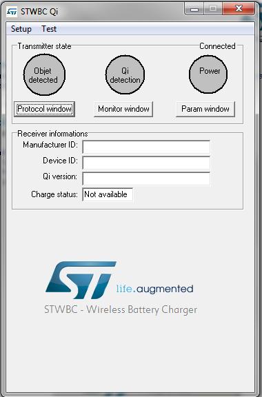
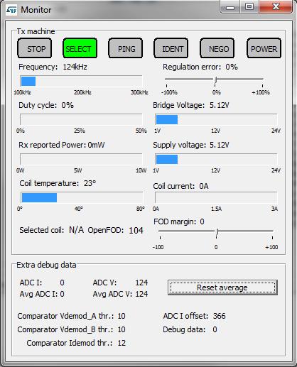
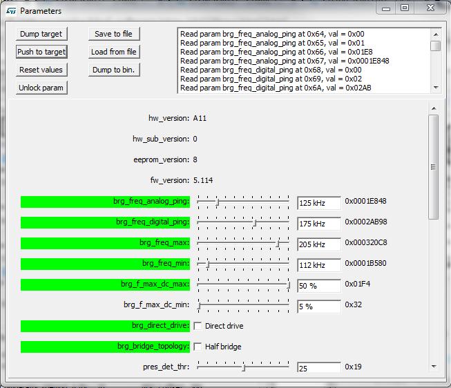
37 GUI for TX 37


38 GUI for RX 38 The GUI allows to set/read: Vout Contract parameters Live AD conversions results Identification data

39 Q&A

40 Thank You 40
Description. Table 1: Device summary Order code Package Packing STWLC33JR CSP (3.97x2.67 mm) 400 μm pitch 52 balls Tape and reel
 400 μm pitch 52 balls Tape and reel") Multi-mode Qi/AirFuel inductive wireless power receiver with transmitter function Data brief Precise voltage and current measurements for FOD function Overvoltage clamp protection HW FSK and ASK demodulators
Multi-mode Qi/AirFuel inductive wireless power receiver with transmitter function Data brief Precise voltage and current measurements for FOD function Overvoltage clamp protection HW FSK and ASK demodulators
COMPLIANCE TESTING OF QI PRODUCTS. Mr. C.H. Lam, Senior Wireless Charging Specialist Intertek Hong Kong, Electrical & Wireless 31 Aug 2017
 COMPLIANCE TESTING OF QI PRODUCTS Mr. C.H. Lam, Senior Wireless Charging Specialist Intertek Hong Kong, Electrical & Wireless 31 Aug 2017 AGENDA 01 Introduction of Qi Compliance Test 02 Introduction of
Successful Qi Transmitter Implementation (making things go right for a change) Dave Wilson 16November2017 v1.
 Dave Wilson 16November2017 v1.") Successful Qi Transmitter Implementation (making things go right for a change) Dave Wilson dwilson@kinet-ic.com 16November2017 v1.0 Overview Introduction Implementation Flow Design Tips and Tricks Important
Successful Qi Transmitter Implementation (making things go right for a change) Dave Wilson dwilson@kinet-ic.com 16November2017 v1.0 Overview Introduction Implementation Flow Design Tips and Tricks Important
Simplified Design of Wireless
 High Efficiency and Simplified Design of Wireless Charging System Hooky Lin ( 林富祈 ) Aug. 31, 2017 Challenge of Wireless Charging Application Wireless charging is facing the challenge that users have experienced
Qi A11 wireless charger transmitter evaluation board based on STWBC. Description
 STEVAL-ISB07V Qi A wireless charger transmitter evaluation board based on STWBC Data brief Features STWBC digital controller 5 W output power Qi.. A certified Foreign object detection (FOD) Resistive and
Methods for Foreign Object Detection in Inductive Wireless Charging. Vladimir Muratov Qi Developer Forum Nov 16, 2017
 Methods for Foreign Object Detection in Inductive Wireless Charging Vladimir Muratov Qi Developer Forum Nov 16, 2017 Agenda What s foreign object detection is all about? Major practical FOD methods Pros
Wireless Power: The Qi standard and bqtesla TM Solutions
 Wireless Power: The Qi standard and bqtesla TM Solutions Wireless power technologies TI, Philips, Fulton, Convenient Power, Sanyo and more Conductive Charging (Wildcharge, Duracell) Wireless Power Consortium
Wireless Charging by Magnetic Resonance
 Francesco Carobolante Vice President Wireless Power Engineering Qualcomm Technologies, Inc. Wireless Charging by Magnetic Resonance ECTC 2014 Wireless Power Transfer Systems Convenience Wireless Charging
Simplifying Design of Wireless Chargers. Silvan Ho May 2017
 Simplifying Design of Wireless Chargers Silvan Ho May 2017 AGENDA Qi Wireless Transmitter Diversity Advantage What a Transmitter is Made of as Universal Transmitter Building Block Simple Design Examples
Wireless Power Solution
 Wireless Power Solution Jeff McCreary President and CEO Analog Semiconductor Forum October 8, 2013 PAGE 1 AGENDA IDT: Who We Are The Next Killer Application Wireless Power User Benefits Market Opportunities
STEVAL-ISB038V1T. 1 W wearable wireless power transmitter based on STWBC-WA. Description. Features
 STEVAL-ISB08VT W wearable wireless power transmitter based on STWBC-WA Data brief USB V input Foreign Object Detection (FOD) optional Graphical interface for monitoring behavior Total reference design
A View From the Other Side of the Chasm
 A View From the Other Side of the Chasm Solving the Technological Challenges Laurence McGarry, Marketing Director, IDT Wireless Power 31st Aug, 2017 1 Wireless Power: A View From The Other Side of the
SP310001/02: Wireless Power Controller for Fast Charging Transmitter
 SP310001/02: Wireless Power Controller for Fast Charging Transmitter 1 Feature Input Voltage: 4.5V to 5.5V Compliant with WPC 1.2.3 to Work with A11 Coils Reliable and Accurate Foreign Object Detection
Qi Developer Forum. Circuit Design Considerations. Dave Wilson 16-February-2017
 WPC1701 Qi Developer Forum Circuit Design Considerations Dave Wilson 16-February-2017 Overview Getting Started Basics The Qi Advantage for Circuit Design Practical Design Issues Practical Implementation
Efficient Power Conversion Corporation
 The egan FET Journey Continues Wireless Energy Transfer Technology Drivers Michael de Rooij Efficient Power Conversion Corporation EPC - The Leader in egan FETs ECTC 2014 www.epc-co.com 1 Agenda Overview
Path to First Try Success Making Qi Compliant PTx and PRx
 Path to First Try Success Making Qi Compliant PTx and PRx Making things go right for a change Dave Wilson V1.0 22Mar2018 Kinetic Technologies - www.kinet-ic.com Overview Introduction Implementation Flow
Successful Qi Receiver Implementation (making things go right for a change) Dave Wilson 16November2017 v1.0
 Dave Wilson 16November2017 v1.0") Successful Qi Receiver Implementation (making things go right for a change) Dave Wilson dwilson@kinet-ic.com 16November2017 v1.0 Overview Introduction Implementation Flow Design Tips and Tricks Important
Successful Qi Receiver Implementation (making things go right for a change) Dave Wilson dwilson@kinet-ic.com 16November2017 v1.0 Overview Introduction Implementation Flow Design Tips and Tricks Important
Measuring Wireless Power Charging Systems for Portable Electronics
 Measuring Wireless Power Charging Systems for Portable Electronics Application Note Introduction Mobile electronics can be found everywhere homes, hospitals, schools, purses, and pockets. With the explosion
This session introduces wireless charging, market applications, and Freescale s activities
 October 2013 This session introduces wireless charging, market applications, and Freescale s activities What is wireless charging? The market Freescale activities How Qi works 2 This session introduces
etatronix PMA-3 Transmitter Tester Manual
 etatronix PMA-3 Transmitter Tester Manual TxTester_Manual_rev1.02.docx 1 Version Version Status Changes Date Responsible 1 Release Initial release 01. Apr. 2015 CW 1.01 Release Updated Figure 4 for better
WIRELESS POWER TRANSFER PROJECT 072 STUDENT NAME : WAMALWA PAUL WAMBOKA SUPERVISOR : DR. DHARMADHIKARY EXAMINER : DR. AKUON
 WIRELESS POWER TRANSFER PROJECT 072 STUDENT NAME : WAMALWA PAUL WAMBOKA SUPERVISOR : DR. DHARMADHIKARY EXAMINER : DR. AKUON BJECTIVES AIN OBJECTIVE Develop a device for wireless power transfer, based on
FOD Transmitter User s Guide
 FOD Transmitter User s Guide Rev 5, 05/21/2014 AVID Technologies, Inc. FOD Transmitter User s Guide Page 2 General Description The AVID FOD (Foreign Object Detection) Transmitter is a standard WPC Qi V1.1
FOD Receiver User s Guide
 FOD Receiver User s Guide 99000076 Rev A 2/17/2013 AVID Technologies, Inc. FOD Receiver User s Guide Page 2 General Description The AVID FOD (Foreign Object Detection) Receiver is a standard WPC V1.1 wireless
System Description Wireless Power Transfer
 Volume I: Low Power Part 1: Interface Definition Version 1.1.1 July 2012 Version 1.1.1 Volume I: Low Power Part 1: Interface Definition Version 1.1.1 July 2012 Wireless Power Consortium, July 2012 Version
DIO6305 High-Efficiency 1.2MHz, 1.1A Synchronous Step-Up Converter
 High-Efficiency 1.2MHz, 1.1A Synchronous Step-Up Converter Rev 1.2 Features High-Efficiency Synchronous-Mode 2.7-5.25V input voltage range Device Quiescent Current: 30µA (TYP) Less than 1µA Shutdown Current
WCT W Single Coil TX V3.1 Runtime Debugging User s Guide
 Document Number: WCT1012V31RTDUG NXP Semiconductors User s Guide Rev. 0 02/2017 WCT1012 15W Single Coil TX V3.1 Runtime Debugging User s Guide 1 Introduction NXP provides the FreeMASTER GUI tool for WCT1012
Wireless Power Receiver for 15W Applications. Description. Features. Typical Applications. Typical Application Circuit. Datasheet P9221-R COUT
 Wireless Power Receiver for 15W Applications P9221-R Datasheet Description The P9221-R is a high-efficiency, Qi-compliant wireless power receiver targeted for applications up to 15W. Using magnetic inductive
P9225-R Evaluation Kit User Manual. Description. Features. Kit Contents. P9225-R-EVK MM EV Board. Top View. Bottom View
 Description The P9225-R-EVK Evaluation Kit demonstrates the functionality, features, and performances of the P9225-R 5W Wireless Power Receiver (Rx). The kit includes the P9225-R Mass-Market (MM) EV Board
WCT W Single Coil TX V3.0 Runtime Debugging User s Guide
 Freescale Semiconductor Document Number: WCT1012V30RTDUG User s Guide Rev. 0, 09/2015 WCT1012 15W Single Coil TX V3.0 Runtime Debugging User s Guide 1 Introduction Freescale provides the FreeMASTER GUI
MP500 PT1-NFC MANUFACTURING OPTIMISED TESTER FOR NFC AND QI ENABLED DEVICES. Testing modes. Business areas
 MANUFACTURING OPTIMISED TESTER FOR NFC AND QI ENABLED DEVICES MP500 PT1-NFC Micropross capitalized on its 15+ years of experience in the supply of test equipment for RFID, NFC devices, as well as wireless
Nuvoton MFID Transponder W55MID15. Data Sheet
 Nuvoton MFID Transponder W55MID15 Data Sheet The information described in this document is the exclusive intellectual property of Nuvoton Technology Corporation and shall not be reproduced without permission
FOD Transmitter User s Guide
 FOD Transmitter User s Guide Rev 4, 07/18/2013 AVID Technologies, Inc. FOD Transmitter User s Guide Page 2 General Description The AVID FOD (Foreign Object Detection) Transmitter is a standard WPC Qi V1.1
ACT8310/ A, PWM Step-Down DC/DCs in TDFN GENERAL DESCRIPTION FEATURES APPLICATIONS SYSTEM BLOCK DIAGRAM ACT8311. Rev 4, 08-Feb-2017
 1.5A, PWM Step-Down DC/DCs in TDFN FEATURES Multiple Patents Pending Up to 95% High Efficiency Up to 1.5A Guaranteed Output Current (ACT8311) 1.35MHz Constant Frequency Operation Internal Synchronous Rectifier
76-81GHz MMIC transceiver (4 RX / 3 TX) for automotive radar applications. Table 1. Device summary. Order code Package Packing
 for automotive radar applications. Table 1. Device summary. Order code Package Packing") STRADA770 76-81GHz MMIC transceiver (4 RX / 3 TX) for automotive radar applications Data brief ESD protected Scalable architecture (master/slave configuration) BIST structures Bicmos9MW, 0.13-µm SiGe:C
STRADA770 76-81GHz MMIC transceiver (4 RX / 3 TX) for automotive radar applications Data brief ESD protected Scalable architecture (master/slave configuration) BIST structures Bicmos9MW, 0.13-µm SiGe:C
HART Modem DS8500. Features
 Rev 1; 2/09 EVALUATION KIT AVAILABLE General Description The is a single-chip modem with Highway Addressable Remote Transducer (HART) capabilities and satisfies the HART physical layer requirements. The
DIO6605B 5V Output, High-Efficiency 1.2MHz, Synchronous Step-Up Converter
 5V Output, High-Efficiency 1.2MHz, Synchronous Step-Up Converter Rev 0.2 Features High-Efficiency Synchronous-Mode 2.7-4.5V input voltage range Device Quiescent Current: 30µA(TYP) Less than 1µA Shutdown
WCT W Single Coil TX V3.1 Reference Design System User s Guide
 Document Number: WCT1012V31SYSUG NXP Semiconductors User s Guide Rev. 0 02/2017 WCT1012 15W Single Coil TX V3.1 Reference Design System User s Guide 1 Introduction This document describes how to use the
Getting started with the STEVAL-ISC003V1 STUSB4710 evaluation board USB PD controller with on-board DC-DC
 User manual Getting started with the STEVAL-ISC003V1 STUSB4710 evaluation board USB PD controller with on-board DC-DC Introduction The STEVAL-ISC003V1 evaluation board is a ready-to-use USB PD source using
1.5MHz, 800mA, High-Efficiency PWM Synchronous Step-Down Converter
 1.5MHz, 800mA, High-Efficiency PWM Synchronous Step-Down Converter Description The is a high efficiency, low-noise, DC-DC step-down pulse width modulated (PWM) converter that goes automatically into PFM
LDS8710. High Efficiency 10 LED Driver With No External Schottky FEATURES APPLICATION DESCRIPTION TYPICAL APPLICATION CIRCUIT
 High Efficiency 10 LED Driver With No External Schottky FEATURES High efficiency boost converter with the input voltage range from 2.7 to 5.5 V No external Schottky Required (Internal synchronous rectifier*)
BluetoothMesh ModuleDatasheet
 BluetoothMesh ModuleDatasheet (WS_D02_8266_V2.2) Shenzhen WE SMART Electronics Co., Ltd Website:www.we smart.cn Mailbox:business@we smart.cn Address:7th FL,Bldg 2B,Wu tong dao industrial park,hangkong
TSDMTX-5V-EVM Wireless Charging Transmitter WIRELESS CHARGING. User Guide TSDMTX-5V-EVM. Dual-Mode (Qi and PMA) Transmitter.
 Transmitter.") TSDMTX-5V-EVM Wireless Charging Transmitter WIRELESS CHARGING User Guide TSDMTX-5V-EVM Dual-Mode (Qi and PMA) Transmitter www.semtech.com Introduction The Semtech TSDMTX-5V-EVM is an evaluation platform
TSDMTX-5V-EVM Wireless Charging Transmitter WIRELESS CHARGING User Guide TSDMTX-5V-EVM Dual-Mode (Qi and PMA) Transmitter www.semtech.com Introduction The Semtech TSDMTX-5V-EVM is an evaluation platform
System Description Wireless Power Transfer
 System Description Volume I: Low Power Part 1: Interface Definition Version 1.0.1 October 2010 Version 1.0.1 System Description System Description Volume I: Low Power Part 1: Interface Definition Version
1.5 MHz, 600mA Synchronous Step-Down Converter
 GENERAL DESCRIPTION is a 1.5Mhz constant frequency, slope compensated current mode PWM step-down converter. The device integrates a main switch and a synchronous rectifier for high efficiency without an
MC-1612 Hardware Design Guide
 LOCOSYS Technology Inc. MC-1612 Hardware Design Guide Version 1.0 Date: 2013/09/17 LOCOSYS Technology Inc. 1 General Rules for Design-in In order to obtain good GPS performances, there are some rules which
MC-1010 Hardware Design Guide
 MC-1010 Hardware Design Guide Version 1.0 Date: 2013/12/31 1 General Rules for Design-in In order to obtain good GPS performances, there are some rules which require attentions for using MC-1010 GPS module.
Power Management & Supply. Design Note. Version 2.3, August 2002 DN-EVALSF2-ICE2B765P-1. CoolSET 80W 24V Design Note for Adapter using ICE2B765P
 Version 2.3, August 2002 Design Note DN-EVALSF2-ICE2B765P-1 CoolSET 80W 24V Design Note for Adapter using ICE2B765P Author: Rainer Kling Published by Infineon Technologies AG http://www.infineon.com/coolset
Rework List for the WCT-15W1COILTX Rev.3 Board
 NXP Semiconductors Document Number: WCT1012V31RLAN Application Note Rev. 0, 02/2017 Rework List for the WCT-15W1COILTX Rev.3 Board 1. Introduction In the WCT-15W1COILTX solution, the Q factor detection
Brushless 5 click. PID: MIKROE 3032 Weight: 25 g
 Brushless 5 click PID: MIKROE 3032 Weight: 25 g Brushless 5 click is a 3 phase sensorless BLDC motor controller, with a soft-switching feature for reduced motor noise and EMI, and precise BEMF motor sensing,
Wireless charging for consumer
 Wireless charging for consumer Introducing a new cost effective system solution to ensure excellent user experience www.infineon.com/wirelesscharging Wireless charging for consumer applications What is
SPECIFICATION EP 1000/1500/2000 Series
 UNINTERRUPTIBLE POWER SYSTEM SPECIFICATION EP 1000/1500/2000 Series Page 1 of 28 1.0 Revision Summary REVISION SECTION DESCRIPTION Formal Release Page 2 of 28 Table of Contents 1. Introduction. 4 2. Block
2015 International Future Energy Challenge Topic B: Battery Energy Storage with an Inverter That Mimics Synchronous Generators. Qualification Report
 2015 International Future Energy Challenge Topic B: Battery Energy Storage with an Inverter That Mimics Synchronous Generators Qualification Report Team members: Sabahudin Lalic, David Hooper, Nerian Kulla,
A Novel Dual-Band Scheme for Magnetic Resonant Wireless Power Transfer
 Progress In Electromagnetics Research Letters, Vol. 80, 53 59, 2018 A Novel Dual-Band Scheme for Magnetic Resonant Wireless Power Transfer Keke Ding 1, 2, *, Ying Yu 1, 2, and Hong Lin 1, 2 Abstract In
Wireless Power Transmitter for Smartphones with Fast Charging Modes for 5W, 7.5W, and 10W Applications. Features. Step-Down Regulator SW_S VIN_LDO
 Wireless Power Transmitter for Smartphones with Fast Charging Modes for 5W, 7.5W, and 0W Applications P924-G Datasheet Description The P924-G is a highly integrated, magnetic induction, wireless power
1.5MHz, 2A Synchronous Step-Down Regulator
 1.5MHz, 2A Synchronous Step-Down Regulator General Description The is a high efficiency current mode synchronous buck PWM DC-DC regulator. The internal generated 0.6V precision feedback reference voltage
DESCRIPTION FEATURES APPLICATIONS TYPICAL APPLICATION. 500KHz, 18V, 2A Synchronous Step-Down Converter
 DESCRIPTION The is a fully integrated, high-efficiency 2A synchronous rectified step-down converter. The operates at high efficiency over a wide output current load range. This device offers two operation
MP4690 Smart Bypass For LED Open Protection
 The Future of Analog IC Technology DESCRIPTION The is a MOSFET based smart bypass for LED open protection, which provides a current bypass in the case of a single LED fails and becomes an open circuit.
MP6902 Fast Turn-off Intelligent Controller
 MP6902 Fast Turn-off Intelligent Controller The Future of Analog IC Technology DESCRIPTION The MP6902 is a Low-Drop Diode Emulator IC for Flyback converters which combined with an external switch replaces
Training Schedule. Robotic System Design using Arduino Platform
 Training Schedule Robotic System Design using Arduino Platform Session - 1 Embedded System Design Basics : Scope : To introduce Embedded Systems hardware design fundamentals to students. Processor Selection
P9241-G Tx Reference Design Layout Guide
 Contents 1. Introduction...2 2. P9241-G Layout Quick Checklist...2 3. Power Circuits...3 4. Bridge Routing...5 5. Bootstrap Capacitors...7 6. VCC5V BUCK and LDO Routing...8 7. VBRIDGE Step-Down Converter...9
FAN5340 Synchronous Constant-Current Series Boost LED Driver with PWM Brightness Control and Integrated Load Disconnect
 April 2010 FAN5340 Synchronous Constant-Current Series Boost LED Driver with PWM Brightness Control and Integrated Load Disconnect Features Synchronous Current-Mode Boost Converter Up to 500mW Output Power
A7534 DC-DC CONVERTER/BOOST(STEP-UP) 0.9V STARTUP, 1MHZ, 300MA IOUT, LOW IQ, SYNCHRONOUS BOOST CONVERTER
 0.9V STARTUP, 1MHZ, 300MA IOUT, LOW IQ, SYNCHRONOUS BOOST CONVERTER") DESCRIPTION The is a step-up converter that provides a boosted output voltage from a low voltage source. Because of its proprietary design, it starts up at a very low input voltage down to 0.9V, and only
DESCRIPTION The is a step-up converter that provides a boosted output voltage from a low voltage source. Because of its proprietary design, it starts up at a very low input voltage down to 0.9V, and only
eorex EP MHz, 600mA Synchronous Step-down Converter
 1.5MHz, 600mA Synchronous Step-down Converter Features High Efficiency: Up to 96% 1.5MHz Constant Switching Frequency 600mA Output Current at V IN = 3V Integrated Main Switch and Synchronous Rectifier
Freescale, the Freescale logo, AltiVec, C-5, CodeTEST, CodeWarrior, ColdFire, ColdFire+, C- Ware, the Energy Efficient Solutions logo, Kinetis,
 April 2013 Freescale, the Freescale logo, AltiVec, C-5, CodeTEST, CodeWarrior, ColdFire, ColdFire+, C- Ware, the Energy Efficient Solutions logo, Kinetis, mobilegt, PEG, PowerQUICC, Processor Expert, QorIQ,
1.5MHz, 3A Synchronous Step-Down Regulator
 1.5MHz, 3A Synchronous Step-Down Regulator FP6165 General Description The FP6165 is a high efficiency current mode synchronous buck PWM DC-DC regulator. The internal generated 0.6V precision feedback reference
Catalog
 - 1 - Catalog 1. Overview... - 3-2. Feature...- 3-3. Application... - 3-4. Block Diagram... - 3-5. Electrical Characteristics...- 4-6. Operation...- 4-1) Power on Reset... - 4-2) Sleep mode...- 4-3) Working
Techcode. 3A 150KHz PWM Buck DC/DC Converter TD1501H. General Description. Features. Applications. Package Types DATASHEET
 General Description Features The TD1501H is a series of easy to use fixed and adjustable step-down (buck) switch-mode voltage regulators. These devices are available in fixed output voltage of 5V, and
TS mA / 1.5MHz Synchronous Buck Converter
 SOT-25 Pin Definition: 1. EN 2. Ground 3. Switching Output 4. Input 5. Feedback General Description The TS3406 is a high efficiency monolithic synchronous buck regulator using a 1.5MHz constant frequency,
AT V Synchronous Buck Converter
 38V Synchronous Buck Converter FEATURES DESCRIPTION Wide 8V to 38V Operating Input Range Integrated two 140mΩ Power MOSFET Switches Feedback Voltage : 220mV Internal Soft-Start / VFB Over Voltage Protection
GENERAL DESCRIPTION APPLICATIONS FEATURES. Point of Loads Set-Top Boxes Portable Media Players Hard Disk Drives
 January 2014 Rev. 1.5.0 GENERAL DESCRIPTION The XRP6657 is a high efficiency synchronous step down DC to DC converter capable of delivering up to 1.5 Amp of current and optimized for portable battery-operated
WIRELESS POWER C O N S O R T I U M
 The Qi Wireless Power Transfer System Parts 1 and 2: Interface Definitions April 2016 COPYRIGHT COPYRIGHT 2015, 2016 by the. All rights reserved. The Qi Wireless Power Transfer System,, Parts 1 and 2:
WIRELESS CHARGING. User Guide. TSWIRX-LI-EVM Wireless Charging Receiver with Li-ion Battery Charger (Rev. 3.00)
") WIRELESS CHARGING TSWIRX-LI-EVM Wireless Charging Receiver with Li-ion Battery Charger (Rev. 3.00) www.semtech.com Introduction The Semtech TSWIRX-LI-EVM is an evaluation platform for the test and experimentation
WIRELESS CHARGING TSWIRX-LI-EVM Wireless Charging Receiver with Li-ion Battery Charger (Rev. 3.00) www.semtech.com Introduction The Semtech TSWIRX-LI-EVM is an evaluation platform for the test and experimentation
HM2259D. 2A, 4.5V-20V Input,1MHz Synchronous Step-Down Converter. General Description. Features. Applications. Package. Typical Application Circuit
 HM2259D 2A, 4.5V-20V Input,1MHz Synchronous Step-Down Converter General Description Features HM2259D is a fully integrated, high efficiency 2A synchronous rectified step-down converter. The HM2259D operates
1.5MHz 600mA, Synchronous Step-Down Regulator. Features
 1.5MHz 600mA, Synchronous Step-Down Regulator General Description is designed with high efficiency step down DC/DC converter for portable devices applications. It features with extreme low quiescent current
Dual Channel, 1.5MHz 800mA, Synchronous Step-Down Regulator. Features. Applications
 Dual Channel, 1.5MHz 800mA, Synchronous Step-Down Regulator General Description is designed with high efficiency step down DC/DC converter for portable devices applications. It features with extreme low
DN0039 Design note. 35 W wide input range flyback converter using HVLED001A quasi resonant Flyback controller and STF10LN80K5.
 DN0039 Design note 35 W wide input range flyback converter using HVLED001A quasi resonant Flyback controller and STF10LN80K5 Designs from our labs describe tested circuit designs from ST labs which provide
High performance ac-dc notebook PC adapter meets EPA 4 requirements
 High performance ac-dc notebook PC adapter meets EPA 4 requirements Alberto Stroppa, Claudio Spini, Claudio Adragna STMICROELECTRONICS via C. Olivetti Agrate Brianza (MI), Italy Tel.: +39/ (039) 603.6184,
Functional Description / User Manual of SIEMENS VDO
 Functional Description / User Manual of SIEMENS VDO Immobilization system smart 451 Type 5WY7776 Name: Department: Telephone: Date: Author: Frank Lindner +49 941-790- 90992 Check: Thomas Heselberger SV
Design and implementation of a LLC-ZCS Converter for Hybrid/Electric Vehicles
 Design and implementation of a LLC-ZCS Converter for Hybrid/Electric Vehicles Davide GIACOMINI Principal, Automotive HVICs Infineon Italy s.r.l. ATV division Need for clean Hybrid and Full Electric vehicles
AT7450 2A-60V LED Step-Down Converter
 FEATURES DESCRIPTION IN Max = 60 FB = 200m Frequency 52kHz I LED Max 2A On/Off input may be used for the Analog Dimming Thermal protection Cycle-by-cycle current limit I LOAD max =2A OUT from 0.2 to 55
Freescale Wireless Charging Solutions
 Freescale Wireless Charging Solutions FTF-CON-F0020 Randy Ryder Business Development A P R. 2 0 1 4 TM External Use Agenda Market Freescale solutions How wireless charging works Difference between inductive
High-Efficiency, 26V Step-Up Converters for Two to Six White LEDs
 19-2731; Rev 1; 10/03 EVALUATION KIT AVAILABLE High-Efficiency, 26V Step-Up Converters General Description The step-up converters drive up to six white LEDs with a constant current to provide backlight
A7115. AiT Semiconductor Inc. APPLICATION ORDERING INFORMATION TYPICAL APPLICATION
 DESCRIPTION The is a high efficiency monolithic synchronous buck regulator using a constant frequency, current mode architecture. Supply current with no load is 300uA and drops to
ST s Solutions for LED General Illumination
 ST s Solutions for LED General Illumination ST LED Lighting Solutions Low Power (75w) Design Software HVLED8XX Controller + MOSFET Embedded with 800V MOSFET
Hydra: A Three Stage Power Converter
 6.101 Project Proposal Paul Hemberger, Joe Driscoll, David Yamnitsky Hydra: A Three Stage Power Converter Introduction Hydra is a three stage power converter system where each stage not only supports a
1.5MHz 800mA, Synchronous Step-Down Regulator. Features. Applications. 2.2 uh. Cout 10uF CER. Cin 4.7 uf CER 2 GND FIG.1
 1.5MHz 800mA, Synchronous Step-Down Regulator General Description is designed with high efficiency step down DC/DC converter for portable devices applications. It features with extreme low quiescent current
Design of analog CMOS circuits
 Design of analog CMOS circuits Design of a fully integrated wireless power transmitter Alexandre Boyer Alexandre.boyer@insa-toulouse.fr www.alexandre-boyer.fr INSA de Toulouse 2017/2018 I. Glossary...
SGM Channel PWM Dimming Charge Pump White LED Driver
 GENERAL DESCRIPTION The SGM3145 is a high performance white LED driver. It integrates current sources and automatic mode selection charge pump. The part maintains the high efficiency by utilizing a 1 /1.5
MP MHz, 700mA, Fixed-Frequency Step-Up Driver for up to 10 White LEDS
 MP3301 1.3MHz, 700mA, Fixed-Frequency Step-Up Driver for up to 10 White LEDS DESCRIPTION The MP3301 is a step-up converter designed to drive WLEDS arrays from a single-cell, lithium-ion battery. The MP3301
A7108. AiT Semiconductor Inc. APPLICATION ORDERING INFORMATION TYPICAL APPLICATION
 DESCRIPTION The is a high efficiency monolithic synchronous buck regulator using a constant frequency, current mode architecture. The device is available in an adjustable version. Supply current with no
1 MHz to 2.7 GHz RF Gain Block AD8354
 1 MHz to 2.7 GHz RF Gain Block AD834 FEATURES Fixed gain of 2 db Operational frequency of 1 MHz to 2.7 GHz Linear output power up to 4 dbm Input/output internally matched to Ω Temperature and power supply
High-Efficiency Step-Up Converters for White LED Main and Subdisplay Backlighting MAX1582/MAX1582Y
 19-2783; Rev 2; 8/05 EVALUATION KIT AVAILABLE High-Efficiency Step-Up Converters General Description The drive up to six white LEDs in series with a constant current to provide display backlighting for
UM2068 User manual. Examples kit for STLUX and STNRG digital controllers. Introduction
 User manual Examples kit for STLUX and STNRG digital controllers Introduction This user manual provides complete information for SW developers about a set of guide examples useful to get familiar developing
DIO6010 High-Efficiency 1.5MHz, 1A Continuous, 1.5A Peak Output Synchronous Step Down Converter
 DIO6010 High-Efficiency 1.5MHz, 1A Continuous, 1.5A Peak Output Synchronous Step Down Converter Rev 1.2 Features Low R DS(ON) for internal switches (top/bottom) 230mΩ/170mΩ, 1.0A 2.5-5.5V input voltage
1. GENERAL DESCRIPTION FEATURES PIN DESCRIPTION BLOCK DIAGRAM... 5
 Table of Contents- 1. GENERAL DESCRIPTION... 2 2. FEATURES... 3 3. PIN DESCRIPTION... 4 4. BLOCK DIAGRAM... 5 5. ELECTRICAL CHARACTERISTICS... 5 5.1 Absolute Maximum Ratings... 5 5.2 D.C. Characteristics...
A7121A. AiT Semiconductor Inc. APPLICATION ORDERING INFORMATION TYPICAL APPLICATION
 DESCRIPTION The is a high efficiency monolithic synchronous buck regulator using a constant frequency, current mode architecture. Supply current with no load is 300uA and drops to
1 MHz to 2.7 GHz RF Gain Block AD8354
 Data Sheet FEATURES Fixed gain of 2 db Operational frequency of 1 MHz to 2.7 GHz Linear output power up to 4 dbm Input/output internally matched to Ω Temperature and power supply stable Noise figure: 4.2
MP A, 24V, 1.4MHz Step-Down Converter
 The Future of Analog IC Technology DESCRIPTION The MP8368 is a monolithic step-down switch mode converter with a built-in internal power MOSFET. It achieves 1.8A continuous output current over a wide input
1.5MHz 600mA, Synchronous Step-Down Regulator. Features
 1.5MHz 600mA, Synchronous Step-Down Regulator General Description is designed with high efficiency step down DC/DC converter for portable devices applications. It features with extreme low quiescent current
TOSHIBA BiCD Digital Integrated Circuit Silicon Monolithic TB62752BFUG
 TOSHIBA BiCD Digital Integrated Circuit Silicon Monolithic Step Up Type DC/DC Converter for White LED The is a high efficient Step-Up Type DC/DC Converter specially designed for constant current driving