Renee Kohl Peter Burrmann Matthew Daly
|
|
|
- Wilfred Watson
- 5 years ago
- Views:
Transcription

1 Renee Kohl Peter Burrmann Matthew Daly
2 Outline Project Summary Background Detailed Description Functional Description and Requirements Equipment and Parts List Preliminary Lab Work Schedule of Spring Tasks
3 Project Summary Convert 120 volt AC grid power to the required 48[V] DC value to charge an electric vehicle battery Discharge the battery into a variable load 120V AC Diode Rectifier AC/DC Boost Converter DC/DC PFC Discharging Load PWM DSP PWM Bidirectional Converter DC/DC Discharging or charging? Charging 48V Battery
4 Project Goals Create a model of PHEV that does not exceed 1000[W] of power No circuit element shall exceed 25[A] for safety purposes Develop a control algorithm using a DSP for the purpose of driving the MOSFET gates in the system

5 Background No previous work has been done at Bradley on this project PHEVs are a growing market
6 Detailed Description Functional Description & Requirements PFC Bi-Directional Converter Protection Circuitry Battery DSP
7 Function Description/Requirements Diode Rectifier Rectifies 120[Vrms] AC grid power Part of Power Factor Correction Current through Rectifier will not exceed 25[A]
8 Function Description/Requirements Boost Converter Boosts input voltage based on MOSFET duty cycle Part of Power Factor Correction Half of Bi-directional Converter
9 Function Description/Requirements Buck Converter Drops input voltage based on MOSFET Duty cycle Half of the Bi-directional Converter
10 Function Description/Requirements Bi-directional Converter To be used in place of the individual Buck and Boost converters Requires more detailed control system
11 Function Description/Requirements Battery Lead Acid Battery Model Lithium-Ion Battery Model
12 Interfacing & Protection Circuitry Current transducer will be used to measure the current Voltage dividers & op-amps to protect DSP board Gate Drivers are in place to protect the DSP from having to much current pulled from it
13 Interfacing & Protection Circuitry
14 DSP Using TMS320F28I2 DSP board to control the PWM duty cycle Switching frequency between 10-15kHz Sensing frequency between 1-10kHz A/D inputs 0-3V PWM output 0-5V


15 MOSFET and Heat Sink IRFP460A N-Type Power MOSFET Drain-Source Voltage VDS = 500V Continuous Drain Current ID = 20A Handles Low Voltage High Freq 55ns minimum rise time Maximum Power Dissipation TC = 25 C SK 145 Heat Sink Thermal Resistance: 13.5K/W
16 MOSFET Gate Driver HCPL E 2.5 A maximum peak output current Power Supply VCC-VEE 10Vmin 20Vmax 250 khz maximum switching speed PWM input
 Average Forward Current (TC = +75 C), IF (AV) =")
17 Diode Rectifier NTE5328 Bridge Rectifier Maximum RMS Bridge Input Voltage = 700V Surge Overload Rating: 400A (Peak) Average Forward Current (TC = +75 C), IF (AV) = 25A

18 Diode VS-HFA50PA60CPBF VR = 600 V Maximum continuous forward current 25A per leg 50A per device

19 Current Transducer L08P050D15 Current Transducer Power Supply VCC ±15V±5% Nominal Primary DC current If = 50AT (wrapping) Maximum Current Ifmax = ±150AT Output Voltage VOUT = ±If Uses hall effect via cable winded through opening to sense current

20 Op-Amp OP484FPZ Op-Amp Supply Voltage Range VS = 3V - 36V Output Voltage High = 2.8Vmin Output Voltage Low = 125mVmax Overvoltage protection
21 Hex Inverter NXP - 74HC04N Inverts input VCC supply voltage = 5.0V

22 Power Supply TRACOPOWER - TMPM VAC input 10W max output Vo = 15VDC Io = 667ma
23 Voltage Regulators LD1117V33C Vin = 15V Vo = 3.3V LM1117T-5.0/NOPB Vin = 15V Vo = 5V


24 Capacitors and Inductors Aluminum Electrolytic Capacitor Capacitance = 1500UF Voltage = 400V Inductance =500UH, Current = 35A

 = 150F")
25 Ultra Capacitors and Battery Voltage and capacity 48V NIMH 13,000mAh Standard discharging rate (1C): 5-10Amp Standard Charging at 1.4 A current -10 Hrs Capacitance (C) = 150F Voltage (V) = 2.7V

26 Digital Signal Processor TMS320F2812 DSP 32-Bit CPU 16 Channel ADC = 3V input 16 PWM Channels Programmable via Simulink and Code Composer
27 Schematics Power Factor Correction
28 Schematics Boost Converter
29 Schematics Buck Converter
30 Simulation PFC Plots
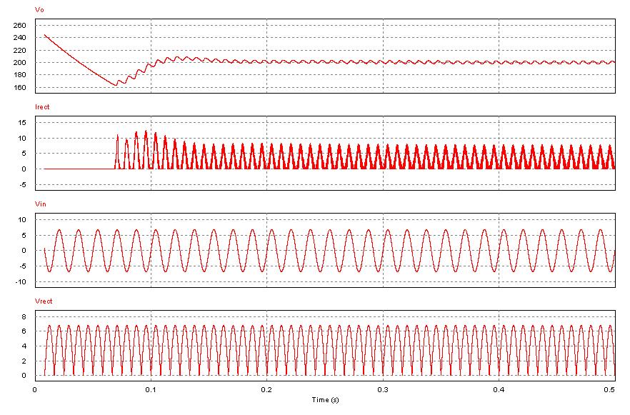
31 Simulation Boost Converter Results Vo= 200
32 Simulation Buck Converter Results Vo= 48
33 DSP Simulations PWM generator Adjustable duty cycle and frequency A/D conversions Value*3/(FFFF) h to calculate input value
34 DSP Simulations C281x 50 W1 constant PWM PWM F2812 ezdsp C281x A0 A1 Scope ADC A2 Scope1 ADC Scope2
35 Small Scale Model Boost converter w/ protection circuitry
36 Small Scale Model 5V Input Duty Cycle: Output: 30% 7.2V 50% 9.6V 70% 15.4V
h= 1.")
37 DSP Simulations Duty Cycle of 50% 2440*16*3/(FFFF) h = 1.76V Voltage Divider Factor = 10.99V Duty Cycle of 30% 2000*16*3/(FFFF)h= 1.46V Voltage Divider Factor = 9.0V
38 DSP Simulations 50% Duty Cycle 30% Duty Cycle
39 What s Next Implement closed loop feedback control for small scale model Build model with ordered parts Continue refining simulations to optimize charging times and reduce overshoot from PI control system
40 Schedule of Tasks Week Schedule of Events/Tasks Spring 2012 Event/Task Test Power Factor Correction Ciructry, Continue developing DSP code Refine Power Factor Correction Ciructry, Continue developing DSP code Test Buck and Boost Converter Circuity, Continue developing DSP code Test Buck and Boost Converter Circuity, Continue developing DSP code Implement Bi-Directional converter with Ultra-Capacitors, Continue developing DSP code Refine Bi-Directional converter with Ultra-Capacitors, Continue developing DSP code Refine Bi-Directional converter with Ultra-Capacitors, Continue developing DSP code Test Entire System and refine DSP Code Swap Ultra Capacitors with 48V battery and test systemmaking changes as needed Refine System/Debug DSP Refine System/Debug DSP Prepare for Presentation Prepare for Presentation Prepare for Presentation
41 Questions?
Electric Vehicle Charger for Plug-In Hybrid Electric Vehicles
 Electric Vehicle Charger for Plug-In Hybrid Electric Vehicles PROJECT PROPOSAL By: Matt Daly Peter Burrmann Renee Kohl Project Advisers: Dr. Woonki Na Dr. Brian Huggins Date: November 18. 2011 phev 2 INTRODUCTION
EV Power Converter Functional Description & Block Diagram
 EV Power Converter Functional Description & Block Diagram By: Sam Emrie Jacob Anderson Advisor: Dr. Woonki Na October 16, 2012 Introduction: This Electric Vehicle Power Converter project is an expansion
2015 International Future Energy Challenge Topic B: Battery Energy Storage with an Inverter That Mimics Synchronous Generators. Qualification Report
 2015 International Future Energy Challenge Topic B: Battery Energy Storage with an Inverter That Mimics Synchronous Generators Qualification Report Team members: Sabahudin Lalic, David Hooper, Nerian Kulla,
idesyn id8802 2A, 23V, Synchronous Step-Down DC/DC
 2A, 23V, Synchronous Step-Down DC/DC General Description Applications The id8802 is a 340kHz fixed frequency PWM synchronous step-down regulator. The id8802 is operated from 4.5V to 23V, the generated
Demonstration. Agenda
 Demonstration Edward Lee 2009 Microchip Technology, Inc. 1 Agenda 1. Buck/Boost Board with Explorer 16 2. AC/DC Reference Design 3. Pure Sinewave Inverter Reference Design 4. Interleaved PFC Reference
Wind Energy Conversion System
 Wind Energy Conversion System Senior Project Report Students: Andy Brown, Basheer Qattum & Ali Gokal Advisors:Dr. Woonki Na and Dr. Brian Huggins May 8, 2012 1 TABLE OF CONTENTS Table of Contents... 2
AT V Synchronous Buck Converter
 38V Synchronous Buck Converter FEATURES DESCRIPTION Wide 8V to 38V Operating Input Range Integrated two 140mΩ Power MOSFET Switches Feedback Voltage : 220mV Internal Soft-Start / VFB Over Voltage Protection
Photovoltaic Power Converter
 Students: Thomas Carley Luke Ketcham Brendan Zimmer Advisors: Dr. Woonki Na Dr. Brian Huggins Bradley University Department of Electrical Engineering 5/10/12 ii Table of Contents Abstract... iv Project
Patent application title: BI-DIRECTIONAL INVERTER-CHARGER
 Search Inventors list Agents list Assignees list List by place Classification tree browser Top 100 Inventors Top 100 Agents Top 100 Assignees Usenet FAQ Index Documents Other FAQs Patent application title:
Level-2 On-board 3.3kW EV Battery Charging System
 Level-2 On-board 3.3kW EV Battery Charging System Is your battery charger design performing at optimal efficiency? Datsen Davies Tharakan SYNOPSYS Inc. Contents Introduction... 2 EV Battery Charger Design...
HF A 27V Synchronous Buck Converter General Description. Features. Applications. Package: TBD
 General Description The is a monolithic synchronous buck regulator. The device integrates 80 mω MOSFETS that provide 4A continuous load current over a wide operating input voltage of 4.5V to 27V. Current
ANP012. Contents. Application Note AP2004 Buck Controller
 Contents 1. AP004 Specifications 1.1 Features 1. General Description 1. Pin Assignments 1.4 Pin Descriptions 1.5 Block Diagram 1.6 Absolute Maximum Ratings. Hardware.1 Introduction. Typical Application.
IJESRT. Scientific Journal Impact Factor: (ISRA), Impact Factor: [Chakradhar et al., 3(6): June, 2014] ISSN:
![IJESRT. Scientific Journal Impact Factor: (ISRA), Impact Factor: [Chakradhar et al., 3(6): June, 2014] ISSN:](/thumbs/89/99209644.jpg "IJESRT. Scientific Journal Impact Factor: (ISRA), Impact Factor: [Chakradhar et al., 3(6): June, 2014] ISSN:") IJESRT INTERNATIONAL JOURNAL OF ENGINEERING SCIENCES & RESEARCH TECHNOLOGY Development of TMS320F2810 DSP Based Bidirectional buck-boost Chopper Mr. K.S. Chakradhar *1, M.Ayesha siddiqa 2, T.Vandhana 3,
IJESRT INTERNATIONAL JOURNAL OF ENGINEERING SCIENCES & RESEARCH TECHNOLOGY Development of TMS320F2810 DSP Based Bidirectional buck-boost Chopper Mr. K.S. Chakradhar *1, M.Ayesha siddiqa 2, T.Vandhana 3,
L1 1 2 D1 B uF R5 18K (Option ) R4 1.1K
 R4 1.1K") PWM CONTROL 3A STEP-DOWN CONVERTER FEATURES DESCRIPTION Input Voltage : 8V to 40V Output Voltage : 3.3V to 38V Duty Ratio : 0% to 100% PWM Control Oscillation Frequency Range is 50K~350KHz by Outside Resistance
PWM CONTROL 3A STEP-DOWN CONVERTER FEATURES DESCRIPTION Input Voltage : 8V to 40V Output Voltage : 3.3V to 38V Duty Ratio : 0% to 100% PWM Control Oscillation Frequency Range is 50K~350KHz by Outside Resistance
MICROCONTROLLER BASED BOOST PID MUNAJAH BINTI MOHD RUBAEE
 MICROCONTROLLER BASED BOOST PID MUNAJAH BINTI MOHD RUBAEE This thesis is submitted as partial fulfillment of the requirement for the award of Bachelor of Electrical Engineering (Power System) Faculty of
Power Electronics in PV Systems
 Introduction to Power Electronics in PV Systems EEN 2060 References: EEN4797/5797 Intro to Power Electronics ece.colorado.edu/~ecen5797 Textbook: R.W.Erickson, D.Maksimovic, Fundamentals of Power Electronics,
Application Note AN-1075
 Application Note AN-1075 Obtaining Low THD and high PF without A PFC By Cecilia Contenti and Peter Green Table of Contents Page I. Introduction...1 II. Test Results...1 III. Electrical Circuit...2 IV.
Designing and Implementing of 72V/150V Closed loop Boost Converter for Electoral Vehicle
 International Journal of Current Engineering and Technology E-ISSN 77 4106, P-ISSN 347 5161 017 INPRESSCO, All Rights Reserved Available at http://inpressco.com/category/ijcet Research Article Designing
DESCRIPTION FEATURES APPLICATIONS TYPICAL APPLICATION. 500KHz, 18V, 2A Synchronous Step-Down Converter
 DESCRIPTION The is a fully integrated, high-efficiency 2A synchronous rectified step-down converter. The operates at high efficiency over a wide output current load range. This device offers two operation
STARTER / GENERATOR MOTOR CONTROLLER
 MIL-PRF-38534 AND 38535 CERTIFIED FACILITY M.S.KENNEDY CORP. STARTER / GENERATOR MOTOR CONTROLLER 4413 (315) 701-6751 FEATURES: 28V/160A Brushless DC motor control capability. 28V/90A Synchronous Boost
OVP 2:1. Wide Range. Protection
 10W, Wide Input Range DIP, Single & Dual Output DC/DC s Key Features High Efficiency up to 88 10 Isolation MTBF > 1,000,000 Hours 2:1 Wide Input Range CSA9-1 Safety Approval Complies with EN522 Class A
Experiment DC-DC converter
 POWER ELECTRONIC LAB Experiment-7-8-9 DC-DC converter Power Electronics Lab Ali Shafique, Ijhar Khan, Dr. Syed Abdul Rahman Kashif 10/11/2015 This manual needs to be completed before the mid-term examination.
EXPERIMENT 7: DIODE CHARACTERISTICS AND CIRCUITS 10/24/10
 DIODE CHARACTERISTICS AND CIRCUITS EXPERIMENT 7: DIODE CHARACTERISTICS AND CIRCUITS 10/24/10 In this experiment we will measure the I vs V characteristics of Si, Ge, and Zener p-n junction diodes, and
Using the EVM: PFC Design Tips and Techniques
 PFC Design Tips and Techniques Features: Bare die attach with epoxy Gold wire bondable Integral precision resistors Reduced size and weight High temperature operation Solder ready surfaces for flip chips
EM5301. Pin Assignment
 5V/2V Synchronous Buck PWM Controller General Description is a synchronous rectified PWM controller operating with 5V or 2V supply voltage. This device operates at 200/300/500 khz and provides an optimal
38V Synchronous Buck Converter With CC/CV
 38V Synchronous Buck Converter With CC/CV GENERAL DESCRIPTION MA5602 is a wide input voltage, high efficiency Active CC step-down DC/DC converter that operates in either CV (Constant Output Voltage) mode
Lecture 4 ECEN 4517/5517
 Lecture 4 ECEN 4517/5517 Experiment 3 weeks 2 and 3: interleaved flyback and feedback loop Battery 12 VDC HVDC: 120-200 VDC DC-DC converter Isolated flyback DC-AC inverter H-bridge v ac AC load 120 Vrms
Application Note, V2.0, March 2006 EVALPFC2-ICE1PCS W PFC Evaluation Board with CCM PFC controller ICE1PCS01. Power Management & Supply
 Application Note, V2.0, March 2006 EVALPFC2-ICE1PCS01 300W PFC Evaluation Board with CCM PFC controller ICE1PCS01 Power Management & Supply N e v e r s t o p t h i n k i n g. Edition 2006-03-27 Published
LED LIGHTING APPLICATION SOLUTION
 LED LIGHTING APPLICATION SOLUTION 2009. V02 General Illumination LED Drivers Technology Overview Product Highlights Application Information Design Examples Overview Regardless of type, color, size or power,
Cree PV Inverter Tops 1kW/kg with All-SiC Design
 Cree PV Inverter Tops 1kW/kg with All-SiC Design Alejandro Esquivel September, 2014 Power Forum 2014 (Bologna) presentation sponsored by: Presentation Outline 1. Meeting an Industry Need a) 1kW/Kg b) No
ENGR4300 Test 3A Fall 2002
 1. 555 Timer (20 points) Figure 1: 555 Timer Circuit For the 555 timer circuit in Figure 1, find the following values for R1 = 1K, R2 = 2K, C1 = 0.1uF. Show all work. a) (4 points) T1: b) (4 points) T2:
Digital Control IC for Interleaved PFCs
 Digital Control IC for Interleaved PFCs Rosario Attanasio Applications Manager STMicroelectronics Presentation Outline 2 PFC Basics Interleaved PFC Concept Analog Vs Digital Control The STNRGPF01 Digital
EM5812/A. 12A 5V/12V Step-Down Converter. Applications. General Description. Pin Configuration. Ordering Information. Typical Application Circuit
 12A 5V/12V Step-Down Converter General Description is a synchronous rectified PWM controller with a built in high-side power MOSFET operating with 5V or 12V supply voltage. It achieves 10A continuous output
ACT111A. 4.8V to 30V Input, 1.5A LED Driver with Dimming Control GENERAL DESCRIPTION FEATURES APPLICATIONS TYPICAL APPLICATION CIRCUIT
 4.8V to 30V Input, 1.5A LED Driver with Dimming Control FEATURES Up to 92% Efficiency Wide 4.8V to 30V Input Voltage Range 100mV Low Feedback Voltage 1.5A High Output Capacity PWM Dimming 10kHz Maximum
Application Note AN-1214
 Application Note LED Buck Converter Design Using the IRS2505L By Ektoras Bakalakos Table of Contents Page 1. Introduction... 2 2. Buck Converter... 2 3. Peak Current Control... 5 4. Zero-Crossing Detection...
CHAPTER 2 DESIGN AND MODELING OF POSITIVE BUCK BOOST CONVERTER WITH CASCADED BUCK BOOST CONVERTER
 17 CHAPTER 2 DESIGN AND MODELING OF POSITIVE BUCK BOOST CONVERTER WITH CASCADED BUCK BOOST CONVERTER 2.1 GENERAL Designing an efficient DC to DC buck-boost converter is very much important for many real-time
CONSONANCE. 4A, Standalone Li-ion Battery Charger CN3761. General Descriptions: Features: Pin Assignment: Applications:
 4A, Standalone Li-ion Battery Charger CN3761 General Descriptions: The CN3761 is a PWM switch-mode lithium ion battery charger controller for 1 cell li-ion battery in a small package using few external
CHAPTER 3. SINGLE-STAGE PFC TOPOLOGY GENERALIZATION AND VARIATIONS
 CHAPTER 3. SINGLE-STAGE PFC TOPOLOG GENERALIATION AND VARIATIONS 3.1. INTRODUCTION The original DCM S 2 PFC topology offers a simple integration of the DCM boost rectifier and the PWM DC/DC converter.
Welcome. High Efficiency SMPS with Digital Loop Control
 Welcome High Efficiency SMPS with Digital Loop Control Presenter: Walter Mosa Company: MagneTek IBM Power and Cooling Technology Symposium September 20-21st FE 1U 800-12 High Density AC/DC Front-End Design
2A, 23V, 380KHz Step-Down Converter
 2A, 23V, 380KHz Step-Down Converter General Description The is a buck regulator with a built-in internal power MOSFET. It achieves 2A continuous output current over a wide input supply range with excellent
PAM2421 EVB User Guide
 EV Board User Guide AE Department 1. Revision Information PAM2421 Date Revision Description Comment 2011/09 V1.0 Initial Release 2. PAM2804 General Description The PAM2421 devices are high-performance,
Low-Noise 4.5A Step-Up Current Mode PWM Converter
 Low-Noise 4.5A Step-Up Current Mode PWM Converter FP6298 General Description The FP6298 is a current mode boost DC-DC converter. It is PWM circuitry with built-in 0.08Ω power MOSFET make this regulator
Non-Synchronous PWM Boost Controller
 Non-Synchronous PWM Boost Controller FP5209 General Description The FP5209 is a boost topology switching regulator for wide operating voltage applications. It provides built-in gate driver pin, EXT pin,
NIKO-SEM N3860V N3860P REV: A CURRENT MODE PWM CONTROLLER GENERAL DESCRIPTION FEATURES DEVICE SELECTION GUIDE
 GENERAL DESCRIPTION The N80 is a low cost, low start-up current, low operating current, current mode PWM controller, specifically designed for the lower stand-by power consumption. The device allows the
1A Buck/Boost Charge Pump LED Driver
 1A Buck/Boost Charge Pump LED Driver Description The Buck/Boost charge pump LED driver is designed for powering high brightness white LEDs for camera flash applications. The automatically switches modes
4.5V to 32V Input High Current LED Driver IC For Buck or Buck-Boost Topology CN5816. Features: SHDN COMP OVP CSP CSN
 4.5V to 32V Input High Current LED Driver IC For Buck or Buck-Boost Topology CN5816 General Description: The CN5816 is a current mode fixed-frequency PWM controller for high current LED applications. The
AIC1340 High Performance, Triple-Output, Auto- Tracking Combo Controller
 High Performance, Triple-Output, Auto- Tracking Combo Controller FEATURES Provide Triple Accurate Regulated Voltages Optimized Voltage-Mode PWM Control Dual N-Channel MOSFET Synchronous Drivers Fast Transient
Advanced Power Electronics Corp.
 PWM CONTROL 2A STEPDOWN CONVERTER FEATURES DESCRIPTION Input Voltage : 3.6V to 20V Output Voltage : 0.8V to VCC Duty Ratio : 0% to 100% PWM Control Oscillation Frequency : 330KHz Typ. SoftStart(SS), Current
Application Note, V1.1, October 2009 EVALPFC2-ICE2PCS W PFC Evaluation Board with CCM PFC controller ICE2PCS01. Power Management & Supply
 Application Note, V1.1, October 2009 EVALPFC2-ICE2PCS01 300W PFC Evaluation Board with CCM PFC controller ICE2PCS01 Power Management & Supply N e v e r s t o p t h i n k i n g. Edition 2009-10-13 Published
Presentation Content Review of Active Clamp and Reset Technique in Single-Ended Forward Converters Design Material/Tools Design procedure and concern
 Active Clamp Forward Converters Design Using UCC2897 Hong Huang August 2007 1 Presentation Content Review of Active Clamp and Reset Technique in Single-Ended Forward Converters Design Material/Tools Design
Calhoon MEBA Engineering School. Study Guide for Proficiency Testing Industrial Electronics
 Calhoon MEBA Engineering School Study Guide for Proficiency Testing Industrial Electronics January 0. Which factors affect the end-to-end resistance of a metallic conductor?. A waveform shows three complete
Reference Design Report for a 21W (42V/0.5A) LED Driver Using SFL900
 LED Driver Using SFL900") Reference Design Report for a 21W (42V/0.5A) LED Driver Using SFL900 Specification Application 90-264VAC Input; 42V/0.5A output LED Driver Author Document Number System Engineering Department SFL900_LED
Reference Design Report for a 21W (42V/0.5A) LED Driver Using SFL900 Specification Application 90-264VAC Input; 42V/0.5A output LED Driver Author Document Number System Engineering Department SFL900_LED
Operation and Maintenance Manual
 WeiKedz 0-30V 2mA-3A Adjustable DC Regulated Power Supply DIY Kit Operation and Maintenance Manual The WeiKedz Adjustable DC Regulated Power Supply provides continuously variable output voltage between
FP A Current Mode Non-Synchronous PWM Boost Converter
 10A Current Mode Non-Synchronous PWM Boost Converter General Description The is a current mode boost DC-DC converter. It is PWM circuitry with built-in 15mΩ power MOSFET make this regulator highly power
AL8811. Description. Pin Assignments. Features. Applications. Typical Application Diagram. Boost/Buck/Inverting DC-DC CONVERTER AL8811
 Boost/Buck/Inverting DC-DC CONVERTER Description The is a monolithic control circuit containing the primary functions required for DC-to-DC converters. These devices consist of an internal temperature
HM V 2A 500KHz Synchronous Step-Down Regulator
 Features HM8114 Wide 4V to 30V Operating Input Range 2A Continuous Output Current Fixed 500KHz Switching Frequency No Schottky Diode Required Short Protection with Hiccup-Mode Built-in Over Current Limit
S24SE/S24DE series 30W Single/Dual Output DC/DC Converter
 FEATURES Efficiency up to 89% Wide input range, 9V-36V Package with Industry Standard Pinout Package Dimension: 25.4 x25.4 x10.2mm (1.0 x1.0 x0.40 )(No HSK) Over voltage protection, hiccup mode Over current
FEATURES DESCRIPTION APPLICATIONS PACKAGE REFERENCE
 DESCRIPTION The is a monolithic synchronous buck regulator. The device integrates 100mΩ MOSFETS that provide 2A continuous load current over a wide operating input voltage of 4.75V to 25V. Current mode
TS3410 1A / 1.4MHz Synchronous Buck Converter
 SOT-25 Pin Definition: 1. EN 2. Ground 3. Switching Output 4. Input 5. Feedback General Description TS3410 is a high efficiency monolithic synchronous buck regulator using a constant frequency, current
AC-DC SMPS: Up to 15W Application Solutions
 AC-DC SMPS: Up to 15W Application Solutions Yehui Han Applications Engineer April 2017 Agenda 2 Introduction Flyback Topology Optimization Buck Topology Optimization Layout and EMI Optimization edesignsuite
S24SP series 60W Single Output DC/DC Converter
 Model List Model Number Input Voltage (Range) Output Voltage Output Current Input Current (typ input voltage) Load Regulation Maxcapacitive Load (Cap ESR>=1mohm;Full Efficiency (typ.) load;5%overshoot
10A Current Mode Non-Synchronous PWM Boost Converter
 10A Current Mode Non-Synchronous PWM Boost Converter General Description The is a current mode boost DC-DC converter. It is PWM circuitry with built-in 15mΩ power MOSFET make this regulator highly power
AT V,3A Synchronous Buck Converter
 FEATURES DESCRIPTION Wide 8V to 40V Operating Input Range Integrated 140mΩ Power MOSFET Switches Output Adjustable from 1V to 25V Up to 93% Efficiency Internal Soft-Start Stable with Low ESR Ceramic Output
Automotive Surge Suppression Devices Can Be Replaced with High Voltage IC
 Automotive Surge Suppression Devices Can Be Replaced with High Voltage IC By Bruce Haug, Senior Product Marketing Engineer, Linear Technology Background Truck, automotive and heavy equipment environments
PWM Controlled, Step-up DC/DC Converter in Tiny Package
 PWM Controlled, Step-up DC/DC Converter in Tiny Package Description The is a high efficiency PWM DC/DC step -up converter with internally compensated current mode controller. The output voltage is set
MA V Synchronous Buck Converter GENERAL DESCRIPTION FEATURES APPLICATION CIRCUIT
 38V Synchronous Buck Converter GENERAL DESCRIPTION The MA5601 is a monolithic synchronous buck regulator. The device integrates two internal power MOSFETs, and provides 2.5A of continuous load current
MP2249 1MHz, 6V, 3A, Low-Voltage Synchronous Step-Down Converter
 The Future of Analog IC Technology MP2249 1MHz, 6V, 3A, Low-Voltage Synchronous Step-Down Converter DESCRIPTION The MP2249 is a 1MHz constant frequency, current mode, PWM step-down converter. The device
MAXREFDES121# Isolated 24V to 3.3V 33W Power Supply
 System Board 6309 MAXREFDES121# Isolated 24V to 3.3V 33W Power Supply Maxim s power-supply experts have designed and built a series of isolated, industrial power-supply reference designs. Each of these
UM mA, 600kHz Step-Up DC-DC Converter UM3433 SOT23-6. General Description. Rev.05 Dec /9
 General Description UM3433 600mA, 600kHz Step-Up DC-DC Converter UM3433 SOT23-6 The UM3433 is synchronous rectified, fixed frequency, step-up DC/DC converter series delivering high efficiency in a low
EUP V/12V Synchronous Buck PWM Controller DESCRIPTION FEATURES APPLICATIONS. Typical Application Circuit. 1
 5V/12V Synchronous Buck PWM Controller DESCRIPTION The is a high efficiency, fixed 300kHz frequency, voltage mode, synchronous PWM controller. The device drives two low cost N-channel MOSFETs and is designed
MP A, 5.5V Synchronous Step-Down Switching Regulator
 The Future of Analog IC Technology DESCRIPTION The MP2120 is an internally compensated 1.5MHz fixed frequency PWM synchronous step-down regulator. MP2120 operates from a 2.7V to 5.5V input and generates
An Improvement in the Virtually Isolated Transformerless Off - Line Power Supply
 An Improvement in the Virtually Isolated Transformerless Off - Line Power Supply Spiros Cofinas Department of Electrotechnics and Computer Science Hellenic Naval Academy Terma Hatzikyriakou, Piraeus GREECE
Using Sipex PWM Controllers for Boost Conversion
 Solved by APPLICATION NOTE ANP1 Introduction: Sipex PWM controllers can be configured in boost mode to provide efficient and cost effective solutions. Circuit operation and design procedure are explained
LM5034 High Voltage Dual Interleaved Current Mode Controller with Active Clamp
 High Voltage Dual Interleaved Current Mode Controller with Active Clamp General Description The dual current mode PWM controller contains all the features needed to control either two independent forward/active
ANP030. Contents. Application Note AP2014/A Synchronous PWM Controller. 1. AP2014/A Specification. 2. Hardware. 3. Design Procedure. 4.
 Contents 1. AP2014/A Specification 1.1 Features 1.2 General Description 1.3 Pin Assignments 1.4 Pin Descriptions 1.5 Block Diagram 1.6 Absolute Maximum Ratings 2. Hardware 2.1 Introduction 2.2 Description
S24SE/S24DE series 15W Single/Dual Output DC/DC Converter
 FEATURES Efficiency up to 89% Wide input range, 9V-36V Package with Industry Standard Pinout Package Dimension: 25.4 x25.4 x10.2mm (1.0 x1.0 x0.40 )(No HSK) Over voltage protection, hiccup mode Over current
ST s Solutions for LED General Illumination
 ST s Solutions for LED General Illumination ST LED Lighting Solutions Low Power (75w) Design Software HVLED8XX Controller + MOSFET Embedded with 800V MOSFET
eorex EP MHz, 600mA Synchronous Step-down Converter
 1.5MHz, 600mA Synchronous Step-down Converter Features High Efficiency: Up to 96% 1.5MHz Constant Switching Frequency 600mA Output Current at V IN = 3V Integrated Main Switch and Synchronous Rectifier
High Accurate non-isolated Buck LED Driver
 High Accurate non-isolated Buck LED Driver Features High efficiency (More than 90%) High precision output current regulation (-3%~+3%) when universal AC input voltage (85VAC~265VAC) Lowest cost and very
LSP5502 2A Synchronous Step Down DC/DC Converter
 FEATURES 2A Output Current Wide 4.5V to 27V Operating Input Range Integrated 20mΩ Power MOSFET Switches Output Adjustable from 0.925V to 24V Up to 96% Efficiency Programmable Soft-Start Stable with Low
Design and implementation of a LLC-ZCS Converter for Hybrid/Electric Vehicles
 Design and implementation of a LLC-ZCS Converter for Hybrid/Electric Vehicles Davide GIACOMINI Principal, Automotive HVICs Infineon Italy s.r.l. ATV division Need for clean Hybrid and Full Electric vehicles
LM , -8.2, -8.4, -12.6, Lithium-Ion Battery Charge Controller
 LM3420-4.2, -8.2, -8.4, -12.6, -16.8 Lithium-Ion Battery Charge Controller General Description The LM3420 series of controllers are monolithic integrated circuits designed for charging and end-of-charge
Features: Phase A Phase B Phase C -DC_A -DC_B -DC_C
 Three Phase Inverter Power Stage Description: The SixPac TM from Applied Power Systems is a configurable IGBT based power stage that is configured as a three-phase bridge inverter for motor control, power
Design and Simulation of Synchronous Buck Converter for Microprocessor Applications
 Design and Simulation of Synchronous Buck Converter for Microprocessor Applications Lakshmi M Shankreppagol 1 1 Department of EEE, SDMCET,Dharwad, India Abstract: The power requirements for the microprocessor
AIC2858 F. 3A 23V Synchronous Step-Down Converter
 3A 23V Synchronous Step-Down Converter FEATURES 3A Continuous Output Current Programmable Soft Start 00mΩ Internal Power MOSFET Switches Stable with Low ESR Output Ceramic Capacitors Up to 95% Efficiency
PWM Controlled, Step-up DC/DC Converter in Tiny Package
 PWM Controlled, Step-up DC/DC Converter in Tiny Package Description The is a high efficiency PWM DC/DC step -up converter with internally compensated current mode controller. The 250kHz switching frequency
eorex (Preliminary) EP3101
 EP3101") (Preliminary) 150 KHz, 3A Asynchronous Step-down Converter Features Output oltage: 3.3, 5, 12 and Adjustable Output ersion Adjustable ersion Output oltage Range, 1.23 to 37 ±4% 150KHz±15% Fixed Switching
(Preliminary) 150 KHz, 3A Asynchronous Step-down Converter Features Output oltage: 3.3, 5, 12 and Adjustable Output ersion Adjustable ersion Output oltage Range, 1.23 to 37 ±4% 150KHz±15% Fixed Switching
Universal High Brightness LED Driver
 FEATURES Over 90% Efficiency 10V to 600V Input Range Constant Current LED Driver Applications from a few ma to more than 1A output LED String From One to Hundreds of Diodes Linear and PWM Dimming Capability
NOT RECOMMENDED FOR NEW DESIGNS REFER TO MP2147 MP Ultra Low Voltage, 4A, 5.5V Synchronous Step-Down Switching Regulator DESCRIPTION FEATURES
 The Future of Analog IC Technology DESCRIPTION The MP38115 is an internally compensated 1.5MHz fixed frequency PWM synchronous step-down regulator. MP38115 operates from a 1.1V to 5.5V input and generates
Engineer-to-Engineer Note
 Engineer-to-Engineer Note EE-339 a Technical notes on using Analog Devices DSPs, processors and development tools Visit our Web resources http://www.analog.com/ee-notes and http://www.analog.com/processors
LLC Resonant Half Bridge Converter
 LLC Resonant Half Bridge Converter Asia Tech-Day August 17 to 7, 009 Hong Huang Applications Engineer Outline Introduction to LLC resonant half bridge converter Benefits Operation principle Design challenges
CHAPTER 4 PI CONTROLLER BASED LCL RESONANT CONVERTER
 61 CHAPTER 4 PI CONTROLLER BASED LCL RESONANT CONVERTER This Chapter deals with the procedure of embedding PI controller in the ARM processor LPC2148. The error signal which is generated from the reference
AT V 5A Synchronous Buck Converter
 FEATURES DESCRIPTION Wide 8V to 38V Operating Input Range Integrated 80mΩ Power MOSFET Switches Output Adjustable from VFB(1V) to 20V Up to 95% Efficiency Internal Soft-Start Stable with Low ESR Ceramic
UNISONIC TECHNOLOGIES CO., LTD UC3750 Preliminary CMOS IC
 UNISONIC TECHNOLOGIES CO., LTD UC3750 Preliminary CMOS IC 600kHZ PWM/PFM STEP-DOWN DC-DC CONTROLLER DESCRIPTION The UTC UC3750 is a high frequency, micropower, voltage mode step-down DC-DC controller IC
QUICK START GUIDE FOR DEMONSTRATION CIRCUIT 968A-A ISOLATED DC/DC POWER CONVERTER LT1952 DESCRIPTION
 QUICK START GUIDE FOR DEMONSTRATION CIRCUIT 98A-A LT9 DESCRIPTION Demonstration circuit 98A-A is isolated input to high current output /8th Brick footprint converter featuring the LT 9 switching controller.
Techcode. 1.6A 32V Synchronous Rectified Step-Down Converte TD1529. General Description. Features. Applications. Package Types DATASHEET
 General Description Features The TD1529 is a monolithic synchronous buck regulator. The device integrates two 130mΩ MOSFETs, and provides 1.6A of continuous load current over a wide input voltage of 4.75V
CONSONANCE CN3306. Step-up Multi-Chemistry Battery Charger IC With PhotoVoltaic Cell MPPT Function. Features: General Description: Pin Assignment
 Step-up Multi-Chemistry Battery Charger IC With PhotoVoltaic Cell MPPT Function CN3306 General Description: The CN3306 is PWM mode step-up multi-chemistry battery charger IC. Its input voltage range is
A 42V Inverter/Rectifier for ISA using Discrete Semiconductor Components
 A 42V Inverter/Rectifier for ISA using Discrete Semiconductor Components Anthony F. J. Murray, Peter Wood, Neeraj Keskar, Jingdong Chen & Alberto Guerra International Rectifier As presented at Future Transportation
Two Stage on-board Battery Charger for Plug in Electric Vehicle Applications
 I J C T A, 9(13) 2016, pp. 6175-6182 International Science Press Two Stage on-board Battery Charger for Plug in Electric Vehicle Applications P Balakrishnan, T B Isha and N Praveenkumar ABSTRACT On board
ML4818 Phase Modulation/Soft Switching Controller
 Phase Modulation/Soft Switching Controller www.fairchildsemi.com Features Full bridge phase modulation zero voltage switching circuit with programmable ZV transition times Constant frequency operation