Configuration of class 210 transmitters by keypad
|
|
|
- Jane Austin
- 5 years ago
- Views:
Transcription


1 Configuration of class 210 transmitters by keypad
2
3 Table of contents 1. Introduction Description of the transmitter Description of the keys Selection of the output signal Protection tip of the sensors Access to the different functions F 100 : Configure the transmitter Access to the firmware version Configure the screen Set the contrast : F Set the backlight duration : F Set the backlight Lock the keypad : F F 200 : Configuration of the channels and measurement units F 300 : Management of the analogue outputs Outputs diagnostic Connection configuration Perform the outputs diagnostic Set the range of the analogue outputs F 500 : Setting of the measurement Autozero (CP210) Pressure measurement integration (CP210) Time-delay between two autozeros (CP211 and CP212) Air velocity measurement integration (CTV210) Add an offset F 600 : Compensation, means of measurement and section settings Temperature compensation (CP 210) Set the unit Set the temperature compensation value temperature Altitude compensation (CO 212, CP 210 and CTV 210) Selection of the means of measurement (CP 210) Select the means of measurement Set the coefficient value of the differential pressure element Set the correction factor value of the air velocity Setting of the type of section and airflow coefficient Select the type of section (CP 210 and CTV 210) Select the unit if the section (CP 210 et CTV 210) Set the size of the section (CP 210 et CTV 210) Set the airflow coefficient (CP 210) Functions recap F F F F F
4
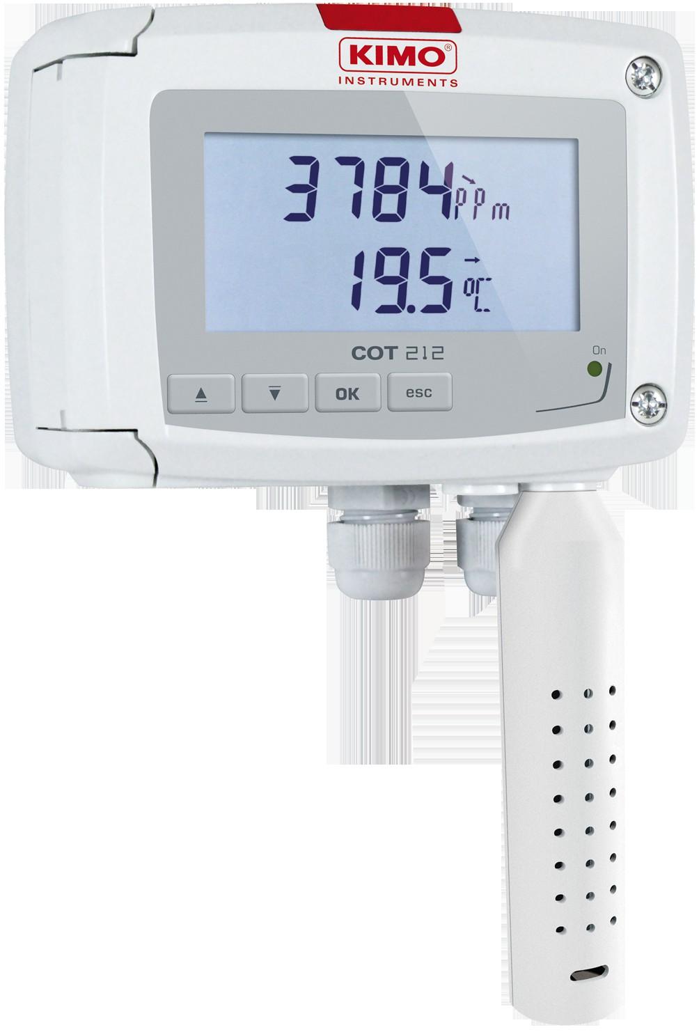
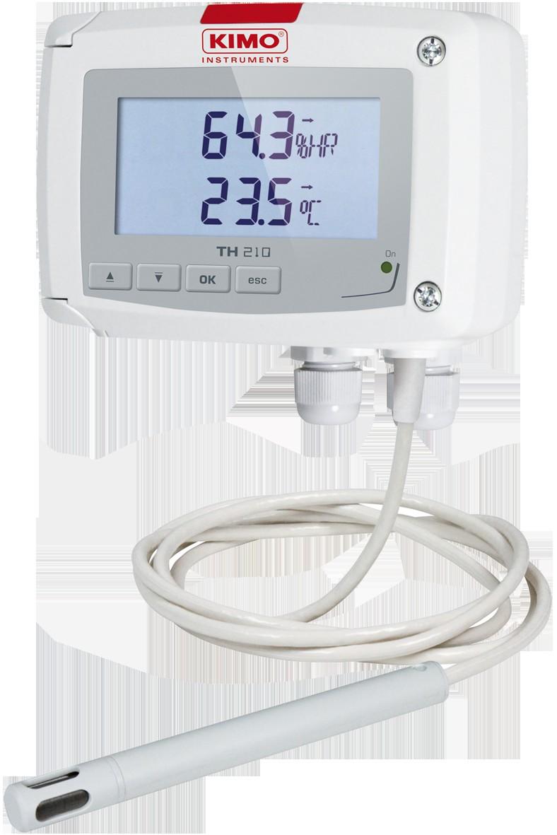
5 1. Introduction 1.1. Description of the transmitter Class 210 transmitters with display can be configured via keypad. It is possible to set measurement units, activate or not a channel,... Principle : the configuration options are accessed via folders and sub-folders. Access is made via a numerical code (full details in this manual). 10 pa Indicator light Up key Down key OK key Esc key Trend indicator : on the screen, a trend indicator represented by a rising arrow, a going down arrow or a stable arrow is displayed above the measurement unit. It means the calculation of a moving average on the last hour (M1) to compare with a moving average on the last 5 minutes (M2) : If M1 = M2, the trend is stable. If M1 < M2 the trend is upwards. If M1 > M2 the trend is downward. Indicator light : the indicator light blinks quickly during the initialization phase of the transmitter then becomes fixed when this phase has been completed. For the pressure transmitters with solenoid valve (CP211 and CP212), it blinks when the solenoid valve is activated Description of the keys Up key : increments a value or a level Down key : decrements a value or a level OK key : validates an input Esc key : cancels an input or backs to the previous step Introduction 5
6 1.3. Selection of the output signal The selection of the output signal in voltage (0-10 V or 0-5 V) or in current (4-20 ma or 0-20 ma) must be performed with the transmitter NOT ENERGIZED and is made with the DIP switch of the electronic board putting the on-off switches as shown on the table below : Configuration 4-20 ma 0-10 V 0-5 V 0-20 ma Combinations 1.4. Protection tip of the sensors It's extremely unwise to remove the protection tip of our hygrometry probes as the sensitive element is very fragile even to light contacts. However, if you have to remove the protection tip, take all possible precautions and avoid any contact with the sensitive element. To remove the protection tip, unscrew it or unclip it. 6 Protection tip to unscrew Protection tip to unscrew Sensitive element Sensitive element Introduction
7 2. Access to the different functions This step is compulsory for each configuration. First, to access to the transmitter functions, and for safety, a safety code must be entered. This safety code is 0101 can not be modified. The transmitter must be energized. Connect the transmitter. Wait for the initialization phase. The screen displays Code with «0000». The first 0 blinks. Press OK to go to the second 0. It blinks. Press Up key to display 1 then press OK. The third 0 blinks. Press OK to go to the fourth 0. Press Up key to display 1 then press OK. The following screen is displayed : Code 0101 F 100 F 100 is for the number of the configuration folder. There are 5 folders : F 100 : folder of the transmitter configuration. See page 8 F 200 : folder of the channels and units of measurement. See page 10 F 300 : folder of the analogue outputs. See page 11 F 500 : folder of the measurement configuration. See page 14 F 600 : folder of the measurement configuration specific to the CO 212, CP210 and CTV210 transmitters. See page 17 To select required folder : F 100 is displayed and 1 is blinking. Press up key until the number of the required folder is display (F 100, F 200, F 300, F 500 or F 600 according to the type of transmitter). If a wrong code is entered, CODE blinks a few seconds on the bottom right of the screen then the measured values are displayed. It is necessary to enter the right code. Access to the different functions 7
8 3. F 100 : Configure the transmitter This folder allows to configure the following parameters of the transmitter : contrast, backlight and keypad locking. It also indicates the firmware version of the transmitter Access to the firmware version The activation code is validated and F 100 is displayed (see previous page). F 101 is displayed with the firmware version number above. (Ex : 1.04) 3.2. Configure the screen Set the contrast : F 110 F 100 folder is displayed. Press Up key to go the F110 folder. F 110 is displayed with the number corresponding to the contrast level between 0 and 5. The contrast number blinks. Set it between 0 and 5 pressing Up and Down keys. When pressing Up or Down key to change the contrast level, there is a lag time of 1 s where the digits disappear then they reappear with the new contrast Set the backlight duration : F 111 It is possible to set the backlight duration : 0 : backlight is inactive 1 : backlight lasts 10 s. 2 : backlight lasts 30 s. 3 : backlight lasts 60 s. 4 : backlight is permanent. Backlight is activated pressing any key (unless the level 0 is selected). F110 sub-folder is displayed. Press Up key. F 111 is displayed with the number corresponding to the backlight duration between 0 and 4. The backlight duration blinks. Set it between 0 and 4 pressing Up and Down keys Set the backlight F111 sub-folder is displayed. Press Up key. F 112 is displayed with the number corresponding to the backlight level between 0 and 10. The backlight level blinks. Set it between 0 and 10 pressing Up and Down keys. 8 F 100 : Configure the transmitter
9 3.3. Lock the keypad : F 140 For more safety and avoid any unwanted manipulation, it is possible to lock the keys of the transmitter. F112 sub-folder is displayed. Press Up key. F 140 is displayed with OFF meaning that the locking is deactivated. OFF blinks. Press Up or Down key, ON blinks, then press OK. LOCK is displayed for a few seconds then the transmitter displays the measured values. All the keys are inactive. To reactivate them : Press for 10 seconds on the OK key. LOCK blinks for a few seconds then the measured values are displayed and the keys are activated. F 100 : Configure the transmitter 9
10 4. F 200 : Configuration of the channels and measurement units This folder allows to activate one two channels and to configure the measurement unit for each channel. Press Up key to go to the folder F blinks and the unit corresponding to the channel 1 is displayed. The unit blinks. Press Up and Down keys to select the required unit according to the type of transmitter. Or when 00 blinks : Press Up or Down key to select the sub-folder F 210 corresponding to the channel 2. Press Up and Down keys to select the required unit according to the type of transmitter. --- sign allows to deactivate the channel. Units available according to the channel and the type of transmitter : CP : Pa, mmh2o, inwg, mbar, mmhg, dapa, kpa, hpa, m/s*, fpm*, m3/h*, l/s*, cfm*, m3/s*, dam3/h*, C, F CP : Pa, mmh2o, inwg, mbar, mmhg, dapa, kpa, hpa, PSI, C, F CTV210 : m/s, fpm, km/h, m3/h, l/s, cfm, m3/s, dam3/h, C, F COT210 : ppm, C, F COT212 : ppm, C, F TM210 : C, F, dt TH210 : %RH, g/kg, Kj/Kg, C td, F td, C tw, F tw, C, F * : units regarding the air velocity and airflow calculation, available on CP transmitters with SQR3 option only. 10 F 200 : Configuration of the channels and measurement units
 or a current (between 0 and 20 ma) according to the setting of the DIP switch of the transmitter electronic board.")

11 5. F 300 : Management of the analogue outputs 5.1. Outputs diagnostic This function allows to check on a measurement device (multimeter, regulator or automate)s the proper functioning of the outputs. The transmitter will generate a voltage (between 0 and 10 V) or a current (between 0 and 20 ma) according to the setting of the DIP switch of the transmitter electronic board. For a 0-10 V output signal, the transmitter will generate 0 5 or 10 V. For a 0-5 V output signal, the transmitter will generate or 5 V. For a 4-20 ma output signal, the transmitter will generate 4 12 or 20 ma. For a 0-20 ma output signal, the transmitter will generate 0 10 or 20 ma Connection configuration Before carrying out the output diagnostics, all connections and configurations of the transmitter must be enabled, to avoid any damage on the transmitter and the measurement device! Select a channel for the outputs diagnostic. OUT1 or OUT2, indicated on the electronic board above the terminal blocks. Connect a measurement device on the channel 1 or on the channel Perform the outputs diagnostic Once the connection to the measurement device is complete, the outputs diagnostic on several check points can be performed : Press Up key to go to the F 300 folder. F 301 blinks, corresponding to the diagnostic of the channel 1. Press Up and Down keys to select the signal that the transmitter has to generate. Screen Generated output Example 0 Deactivated - 1 Simulates 0 % of the output range On the 0-10V range, the transmitter will generate 0 V. 2 Simulates 50 % of the output range On the 0-10V range, the transmitter will generate 5 V. 3 Simulates 100 % of the output range On the 0-10V range, the transmitter will generate 10 V. F 300 : Management of the analogue outputs 11
12 If the deviations are too large (> 0,05V or > 0,05mA) between the signal issued and the value displayed on the multimeter, we recommend that you return the transmitter to our factory. For the diagnostic of the channel 2, go to F 311 folder and do the same procedure as the channel Set the range of the analogue outputs This function allows to modify the range of the analogue outputs. Values to enter depend on the unit of measurement and not on the measurement range of the transmitter. Ex : on a CP 211 pressure transmitter (0 to ±1000 Pa) with a reading in mmh2o, the minimum and maximum ranges must be configured on measuring range of 0 to ±102 mmh2o. See conversion chart above. Press Up key to go to folder F 302 corresponding to the low range of the channel 1. The first digit of the low range blinks. Enter with Up and Down keys the figure value or the negative sign of the value then press OK. The second digit blinks. Enter with Up and Down keys its value then press OK. Perform the same procedure for the following figures. Press OK when the last figure has been configured. F 302 blinks, the low range is configured. Press Up key then press OK to enter in the folder F 303 corresponding to the high range of the channel 1. The first digit of the high range blinks. Enter with Up and Down keys the figure value or the negative sign of the value then press OK. The second digit blinks. Enter with Up and Down keys its value then press OK. Perform the same procedure for the following figures. Press OK when the last figure has been configured. F 303 blinks, the high range is configured. To set the low and high ranges of the channel 2, go to the folders F 312 (low range) and F 313 (high range) and follow the setting procedure of the channel 1. Unit of measurement conversion chart Pressure Pa mmh2o InWG mbar mmhg kpa PSI dapa hpa CP211 ±100 ±10.2 ±0.40 ±1.00 ±0.75 ± ±10.0 ±1.00 CP212 ±1000 ±102.0 ±4.01 ±10.00 ±7.50 ± ±100.0 ±10.00 CP213 ± ± ±40.14 ± ±75.00 ± ± ± CP214 - ±5099 CP215 - ±20394 ±802.9 ± ±200.7 ±500 ± ±7.25 ±5000 ± ± ±29.00 ±20000 ± F 300 : Management of the analogue outputs
13 Temperature TH210 C F Ambient model From 0.0 to From to Model with polycarbonate probe From to From -4.0 to Model with stainless steel probe From to From to TM210 C F Ambient model From 0.0 to From to Terminal block model From to From to CTV210 / COT210 / COT212 C F Ambient model From 0.0 to From to CP210 C F On terminal block From to From to Air velocity CTV210 m/s fpm km/h Standard From 0 to 30 From 0 to 5905 From 0 to 108 Omnidirectional From 0 to 5 From 0 to 984 From 0 to 18 F 300 : Management of the analogue outputs 13
14 6. F 500 : Setting of the measurement In order to compensate a potential drift of the transmitter, it is possible to add an offset to value displayed by the transmitter. Adding an offset is only possible for the measured parameters (temperature, humidity, pressure, air velocity...). It is not possible to add it one for the calculated parameters (airflow, psychrometry..) Autozero (CP210) Class 210 pressure transmitters have an autozero which guarantees a good reliability of the measurement in high and low ranges. The autozero compensates for any long-term drifts of the sensitive element, with the manual adjusting of the zero. To perform a self-calibration : Unplug the 2 pressure connections tubes. Press autozero button. (See Connection on the datasheet). If the instrument has a display, it is possible to perform an autozero pressing for 3 seconds the Esc key. AutoZ is displayed briefly meaning the autozero has been well performed. On CP 211 and CP 212 transmitters, it is not necessary to unplug the 2 pressures connections tubes (see chapter 6.3) Pressure measurement integration (CP210) This function is available on CP210 transmitters only. The pressure measurement element is very sensitive and reacts to pressure changes. When making measurements in unstable air movement conditions, the pressure measurement may fluctuate. The integration coefficient (from 0 to 9) makes an average of the measurements ; this helps to avoid any excessive variations and guarantees a stable measurement. New displayed value = [((10 - Coef.) x New value) + (Coef. x Old value)] /10 Example : CP212 ( Pa) Current measurement : 120 Pa New measurement : 125 Pa The pressure source being stable, the user selects a low integration. Integration : 1, maximum admitted variation ±10 Pa. The variation is lower than 10 Pa, it is possible to apply the integration calculation formula. Next displayed value : ((9 * 125) + (1 *120 ))/10 = i.e, 124 Pa. If the new measurement had been de 131 Pa, the next displayed value would have been 100% of the new value i.e, 131 Pa. Press Up key to go to folder F 500. Set the integration value with Up and Down keys. This value must be between 0 and 9 with : Coefficient 0 : no integration, important fluctuation of the displayed value. Coefficient 9 : maximum integration, more stable measurement display Time-delay between two autozeros (CP211 and CP212) On transmitters having a solenoid valve for autozero (CP 211 and CP 212), it is possible to set an interval between 2 autozeros : 14 F 500 : Setting of the measurement
15 Press Up key to go to folder F 500. Press Up key to go to folder F 510. The duration between two autozeros is displayed. Set it with Up and Down keys. This time-delay must be between 0 (no autozero) and 60 minutes. Press OK to validate the duration Air velocity measurement integration (CTV210) This function is available on CTV210 transmitters only. The air velocity measurement element of the class 200 is very sensitive and reacts to air velocity changes. When making measurements in unstable air systems, the air velocity measurement may fluctuate. The integration coefficient (from 0 to 9) makes an average of the measurement ; this helps to avoid any excessive variations and guarantees a stable measurement. New displayed value = [((10 - Coef.) x New value) + (Coef. x Old value)] /10 Example : CTV210 with hot wire (0-30 m/s) Current measurement : 2 m/s New measurement : 8 m/s The air velocity source being unstable, the user selects a strong integration. Integration : 7. The variation is lower than 10 m/s, it is possible to apply the integration calculation formula. Next displayed value : ((2 * 8) + (7 *2 ))/10 = 3 m/s. Press Up key to go to folder F 501. Set the integration value with Up and Down keys. This value must be between 0 and 9 with : Coefficient 0 : no integration, important fluctuation of the displayed value. Coefficient 9 : maximum integration, more stable measurement display Add an offset The transmitter is power on. Press Up key to go to folder F 500. F 521 blinks, corresponding to the setting folder for the main parameter. The first number of the offset blinks. Enter with Up and Down keys the number value or the negative sign of the value then press OK. The second number blinks. Enter with Up and Down keys its value then press OK. Repeat the procedure for the following numbers. Press OK when the last number is set. F 521 blinks, the offset for the main parameter is configured. Press Up key then press OK to enter in the F 531 folder corresponding to the offset of the second parameter. F 500 : Setting of the measurement 15
16 The first number of the offset blinks. Enter with Up and Down keys the number value or the negative sign of the value then press OK. The second number blinks Enter with Up and Down keys its value then press OK. Repeat the procedure for the following numbers. Press OK when the last number is set. F 531 blinks, the offset for the main parameter is configured. The unit of the offset is set by default and can not be modified. If this unit is not the same than the unit of measurement, a conversion must be done. 16 F 500 : Setting of the measurement
17 7. F 600 : Compensation, means of measurement and section settings 7.1. Temperature compensation (CP 210) It is possible to modify the temperature compensation. Indeed the air velocity and airflow measured with a differential probe (such as Pitot tube, Debimo blade, orifice plate...) depends on the working temperature. Then, it is required to enter the working temperature to get more accurate results Set the unit Press Up key to go to F 600 folder. Select 0 for C or 1 for F then press OK Set the temperature compensation value temperature Press Up key to go to F 602 folder. The 1st digit blinks. Press Up or Down key to set the temperature sign : 0 for a positive temperature ou for a negative temperature. The 2nd digit blinks. Press Up or Down key to set the digit then press OK. Repeat the procedure for the following digits. Press OK when the last digit has been set to validate the temperature compensation value Altitude compensation (CO 212, CP 210 and CTV 210) If measurements are performed at a specific altitude, it is advised to set the altitude in which the transmitter is. Press Up key to go to F 605 folder. The 1st digit blinks. Press Up or Down to set the digit : only 1 and 0 are available The 2nd digit blinks. Press Up and Down key to set the digit then press OK. Repeat the procedure to set the following digits. Press OK when the last digit has been set to validate the altitude value Selection of the means of measurement (CP 210) F 600 : Compensation, means of measurement and section settings 17
18 The calculation of air velocity being calculated from the pressure (for a CP 210 transmitter) and from a differential pressure element, the used differential pressure element must be selected to perform the measurements. The coefficient of this element and the air velocity correction coefficient must be then entered Select the means of measurement Press Up key to go to F 610 folder. Select 0, 1, 2 or 3 for : 0 : Pitot L tube 1 : Pitot S tube 2 : Debimo blade 3 : Factor Press Up key to go to F 611 folder. Set the 1st digit with Up and Down keys then press OK to set the 2 nd digit. Repeat the procedure to set the following digits. Press OK when the last digit has been set to validate the coefficient. This coefficient is between and Set the coefficient value of the differential pressure element Set the correction factor value of the air velocity Press Up key to go to F 612 folder. Set the 1st digit with Up and Down keys then press OK to set the 2 nd digit. Repeat the procedure to set the following digits. Press OK when the last digit has been set to validate the factor. This coefficient is between and Setting of the type of section and airflow coefficient This function is available for CP210 transmitters with SQR3 option only Select the type of section (CP 210 and CTV 210) 18 F 600 : Compensation, means of measurement and section settings
19 Press Up key to go to F 620 folder. Select 0, 1, or 2 for : 0 : rectangular section 1 : circular section 2 : coefficient Select the unit if the section (CP 210 et CTV 210) Press Up key to go to F 621 folder. Select 0 or 1 for : 0 : section in mm 1 : section in inch Set the size of the section (CP 210 et CTV 210) For a rectangular section : Press Up key to go to F 622 folder to set the length of the rectangular section. Set the length with Up and Down keys. Press OK when the last digit has been set to validate the length. Press Up key to go to F 623 folder to set the width of the rectangular section Set the width with Up and Down keys. Press OK when the last digit has been set to validate the width. For a circular section : Press Up key to go to F 624 folder to set the diameter of the circular section. Set the diameter with Up and Down keys. Press OK when the last digit has been set to validate the diameter Set the airflow coefficient (CP 210) This function is available on CP 210 with SQR3 option only. This coefficient allows to calculate an airflow from the pressure. It is indicated by the manufacturer that supplies air vents with pressure connections (+ and -). From the square root of the measured pressure (Delta P), and this coefficient, you will get the airflow : Airflow=C D Δ pressure F 600 : Compensation, means of measurement and section settings 19
20 Press Up key to go to F 625 folder to set the coefficient value. Set the coefficient with Up and Down keys. Press OK when the last digit has been set to validate the coefficient. This coefficient must be between and Press Up key to go to F 626 folder to set the unit of measurement. Select 0, 1, 2, 3 or 4 for : 20 CP211 CP212 CP213 CP214 CP215 0 Pa Pa Pa mbar mbar 1 mmh2o mmh2o mmh2o inwg inwg 2 inwg inwg inwg kpa kpa 3 mbar mbar mbar PSI PSI 4 mmhg mmhg mmhg mmhg mmhg F 600 : Compensation, means of measurement and section settings
21 8. Functions recap 8.1. F 100 Code Description Possibilities F 101 Firmware version - F 110 Screen contrast From 0 to 5 F 111 Backlight duration From 0 to 4 F 112 Screen backlight From 0 to 10 F 140 Keypad locking Off 8.2. F 200 Code Description Possibilities F 200 Change unit channel 1 / deactivation of the channel According to the type of transmitter (see below) F 210 Change unit channel 2 / deactivation of the channel According to the type of transmitter (see below) Units available according to the channel and the type of transmitter : CP : Pa, mmh2o, inwg, mbar, mmhg, dapa, kpa, hpa, m/s*, fpm*, m3/h*, l/s*, cfm*, m3/s*, dam3/h*, C, F CP : Pa, mmh2o, inwg, mbar, mmhg, dapa, kpa, hpa, PSI, C, F CTV210 : m/s, fpm, km/h, m3/h, l/s, cfm, m3/s, dam3/h, C, F COT210 : ppm, C, F COT212 : ppm, C, F TM210 : C, F, dt TH210 : %RH, g/kg, Kj/Kg, C td, F td, C tw, F tw, C, F * : units regarding the air velocity and airflow calculation, available on CP transmitters with SQR3 option only. --- sign allows to deactivate the channel. Functions recap 21
22 8.3. F 300 Code Description F 301 Diagnostic of the channel 1 : generation of current or voltage Possibilities Display Generation according to the output signal 0-10 V 0-5 V 0 no generation 1 0V 0V 0 ma 4 ma 2 5V 2.5 V 10 ma 12 ma 3 10 V 5V 20 ma 20 ma F 302 Low rang of the channel 1 According to the type of transmitter F 303 High range of the channel 1 According to the type of transmitter F 311 Diagnostic of the channel 2 : generation of current or voltage Display Generation according to the output signal 0-10 V 0-5 V ma 4-20 ma no generation 1 0V 0V 0 ma 4 ma 2 5V 2.5 V 10 ma 12 ma 3 10 V 5V 20 ma 20 ma F 312 Low rang of the channel 2 According to the type of transmitter F 313 High range of the channel 2 According to the type of transmitter ma 4-20 ma F 500 Code Transmitter Description Possibilities F 500 Only CP 210 Integration of the measurement (pressure) From 0 to 9 F 501 Only CTV 210 Integration of the measurement (air velocity) From 0 to 9 F 510 Only CP 210 with solenoid valve Time-delay between two autocalibrations From 0 to 60 min F 521 All Offset main parameter According to the measurement range of the transmitter F 531 All Offset secondary parameter According to the measurement range of the transmitter 22 Functions recap
23 8.5. F 600 Code Transmitter Description Possibilities F 600 CP 210 Temperature unit 0 : C 1 : F F 602 CP 210 Temperature compensation F 605 CO 212, CP 210 et CTV 210 Altitude compensation F 610 CP 210 Means of measurement F 611 CP 210 Differential pressure coefficient F 612 CP 210 Factor of air velocity correction F 620 CP 210 et CTV 210 Type of section 0 : Rectangular 1 : Circular 2 : Coefficient F 621 CP 210 et CTV 210 Unit of the section 0 : mm 1 : inch F 622 CP 210 et CTV 210 Rectangular section length F 623 CP 210 et CTV 210 Rectangular section width F 624 CP 210 et CTV 210 Circular section diameter F 625 CP 210 Airflow coefficient F 626 CP 210 Unit of measurement 0 : Pitot L 1 : Pitot S 2 : Debimo blade 3 : Factor Pa, mbar, mmh2o, inwg, kpa, mmhg, PSI (according to the transmitter, see table below) CP211 CP212 CP213 CP214 CP215 0 Pa Pa Pa mbar mbar 1 mmh2o mmh2o mmh2o inwg inwg 2 inwg inwg inwg kpa kpa 3 mbar mbar mbar PSI PSI 4 mmhg mmhg mmhg mmhg mmhg Functions recap 23
24 NTang transmitters_class_210-05/09/13 - RCS (24) Périgueux Non-contractual document We reserve the right to modify the characteristics of our products without prior notice.
Configuration of CPE 310-S and CPE 311-S transmitters by keypad
 Configuration of CPE 310-S and CPE 311-S transmitters by keypad Table of contents 1. Introduction...5 1.1. Description of the transmitter...5 1.2. Description of the keys...5 1.3. Protection tips of the
Configuration of C310 multifunction transmitters by keypad
 Configuration of C310 multifunction transmitters by keypad Table of contents 1. Introduction...5 1.1. Description of the transmitter...5 1.2. Description of the keys...5 1.3. Protection tips of the sensor...6
User Manual TH300 > CTV310 > TH300 > < TT300 TT300 > Air velocity. Temperature Humidity. Temperature. Pressure CP300 > Standard probe.
 User Manual Configuration of Class 00 Transmitters New New Keypad Remote control network Temperature Humidity Air velocity TH00 Remote probe Pressure TH00 Standard probe CTV0 Standard probe Temperature
Temperature Humidity < THA 300
 User Manual Presure Temperature Humidity Air Velocity Air Flow USER MANUAL Configuration of CPA00 and THA00 New New Remote control MODBUS System Temperature Humidity < THA 00 Pressure CPA 00 > Summary.
LCC-100 software User manual
 User Manual Pressure Temperature Humidity Air Velocity Airflow Sound level New LCC-100 software User manual Configuration software for Monostats - Class 50 and 100 units - ranges - relays - set points
Differential pressure transmitter CP 111 CP 112 CP 113
 Differential pressure transmitter CP CP CP KEY POINTS Ranges from 00/00 Pa to 0000/0000 Pa (accding to models) Configurable intermediary ranges 00 V 0 m output, active, power supply Vac/Vdc ( wires) 0
Sensors Transmitters. Pressure / Temperature / Humidity / Air velocity / Airflow / Air quality / Solar / Light
 Sensors Transmitters Pressure / Temperature / Humidity / Air velocity / Airflow / Air quality / Solar / Light 1 Sensors Transmitters Pressure / Temperature / Humidity / Air velocity Airflow / Air quality
JUMO Wtrans E01. Measuring probe for humidity, temperature, and CO 2 with wireless data transmission. Brief description. Universal Wtrans receiver
 Page 1/13 JUMO Wtrans E01 Measuring probe for humidity, temperature, and CO 2 with wireless data transmission Humidity from 0 to 100 % RH (incl. -40 to +80 C) or CO 2 from 0 to 2000/5000/10000 ppm or Temperature
USER MANUAL RASI 900 / RASI 901. EiUK Eurotron Instruments (UK) ltd
 ltd") USER MANUAL RASI 900 / RASI 901 EiUK Eurotron Instruments (UK) ltd 2 We are grateful for your purchase of EiUK Eurotron Instruments (UK) ltd Gas Analyzer First read this instruction manual carefully until
USER MANUAL RASI 900 / RASI 901 EiUK Eurotron Instruments (UK) ltd 2 We are grateful for your purchase of EiUK Eurotron Instruments (UK) ltd Gas Analyzer First read this instruction manual carefully until
Thermo-hygrometer-anemometer VT 210
 Thermo-hygrometer-anemometer VT 210 Measurement of temperature, hygrometry and air velocity (depending on models) Interchangeable modules Interchangeable measurement modules 1 device = several possible
Series 10-ZSE80/10-ISE80
 Series 0-ZSE80/0-ISE80 RoHS -Color Display Digital Pressure Switch For General Fluids Directional Control Valves For positive 0 80 For vacuum/ compound 80 80F N P B R T S V Rated range Symbol -X50 Clean
MITOS VT6 AIR USER MANUAL. 02/10/2015 Manual_MITOS_VT6_AIR_ver3p3_eng
 MITOS VT6 AIR USER MANUAL 02/10/2015 Manual_MITOS_VT6_AIR_ver3p3_eng Summary: GENERAL DESCRIPTION... 3 GENERAL FEATURES... 3 FUNCTIONING PARAMETERS... 4 FUNCTIONING MODE OF THE MITOS VT6 AIR... 7 FUNCTIONING
Series 10-ZSE30A(F)/10-ISE30A
/10-ISE30A") Series 10-ZSEA(F)/10-ISEA RoHS 2-Color Display High-Precision Digital Pressure Switch Clean series For positive For vacuum/ compound Rated range ISEA 0.1 to 1 MPa How to Order 10 ISEA 01 N M 01 N01 C4H
Series 10-ZSEA(F)/10-ISEA RoHS 2-Color Display High-Precision Digital Pressure Switch Clean series For positive For vacuum/ compound Rated range ISEA 0.1 to 1 MPa How to Order 10 ISEA 01 N M 01 N01 C4H
Operating instructions. Combined pressure sensor PN /00 11/03
 Operating instructions R Combined pressure sensor PN 7080/00 /03 Contents afety instructions..................................... page 5 Controls and indicating elements.......................... page
FST Series HUMIDITY-TEMPERATURE TRANSMITTERS INSTRUCTION MANUAL
 FST Series HUMIDITY-TEMPERATURE TRANSMITTERS INSTRUCTION MANUAL 20020628 CONTENTS DESCRIPTION... 3 OPERATION... 4 Power Supply...4 Output Range...4 Temperature Operating Range and Temperature Limits...4
Programmable transmitter of temperature, relative humidity and other derived humidity values with 4-20 ma outputs Instruction Manual
 T3110 TRANSMITTER Programmable transmitter of temperature, relative humidity and other derived humidity values with 4-20 ma outputs Instruction Manual Instruction manual for use of T3110 transmitter Transmitter
Operating instructions. Electronic pressure sensor PY2068 ENGLISH
 Operating instructions R Electronic pressure sensor PY068 704803/00 06/00 ENGLIH Contents afety instructions................................ page 0 Controls and indicating elements.....................
Simplified Operations for TM-3100 Series Digital Tachometer
 Simplified Operations for TM-3100 Series Digital Tachometer The TM-3100 series Digital Tachometers has the most fundamental function in rotational measurement of four standard models (rotation speed display,
SITRANS F flowmeters. SITRANS F System information MAGFLO electromagnetic flowmeters 4/9
 Overview MAGFLO family MAGFLO electromagnetic are designed for measuring the flow of electrically conductive mediums. The patented MAGFLO Verificator guarantees accurate measurement and simple verification.
ED701 General Industry Pressure Transmitter
 ED701 General Industry Pressure Transmitter Standard industrial process connections Complete range of electrical connections 4... 20 ma and Voltage outputs Accuracy: 0.1%, 0.2% and 0.4% FS Quick response
User's Guide. Heavy Duty CFM Thermo-Anemometer. Model Washington Street Melrose, MA Phone Toll Free
 User's Guide 99 Washington Street Melrose, MA 02176 Phone 781-665-1400 Toll Free 1-800-517-8431 Visit us at www.testequipmentdepot.com Heavy Duty CFM Thermo-Anemometer Model 407113 above is inclusive and
SITRANS F flowmeters. SITRANS F M System information MAGFLO electromagnetic flowmeters. 4/18 Siemens FI
 Function All are based on Faraday s law of induction: U M = B v d k U M = Measured voltage induced in the medium perpendicular to the magnetic field and the flow direction. The voltage is tapped at two
Programmable transmitter of temperature, relative humidity and other derived humidity values with 4-20 ma outputs Instruction Manual
 T3111 TRANSMITTER Programmable transmitter of temperature, relative humidity and other derived humidity values with 4-20 ma outputs Instruction Manual Instruction manual for use of T3111 transmitters Transmitter
Programmable transmitter of temperature, relative humidity and other derived humidity values with 0 to 10 V outputs Instruction Manual
 T0213 TRANSMITTER Programmable transmitter of temperature, relative humidity and other derived humidity values with 0 to 10 V outputs Instruction Manual Instruction manual for use of T0213 transmitter
Programmable transmitter of temperature, relative humidity and other derived humidity values with 4-20 ma outputs Instruction Manual
 T3111 TRANSMITTER Programmable transmitter of temperature, relative humidity and other derived humidity values with 4-20 ma outputs Instruction Manual Instruction manual for use of T3111 transmitters Transmitter
Posiflow Proportional Solenoid Valves % ^ ) 2/2. Brass or Stainless Steel Bodies 1/8" to 1/2" NPT. Proportional Valves. Features.
 2/2. Brass or Stainless Steel Bodies 1/8 to 1/2 NPT. Proportional Valves. Features.") 4 Posiflow Solenoid Brass or Stainless Steel Bodies 1/8" to 1/2" NPT 2/2 Features Flow rates adjustable between 0% and 100% of rating Control achieved by applying straight voltage between 0 and 24 VDC
4 Posiflow Solenoid Brass or Stainless Steel Bodies 1/8" to 1/2" NPT 2/2 Features Flow rates adjustable between 0% and 100% of rating Control achieved by applying straight voltage between 0 and 24 VDC
FAST SAMPLING CONVERTER
 FAST SAMPLING CONVERTER ML4-F1 HIGH SAMPLING RATE CONVERTER (UP TO 400 SAMPLES/SECOND) Warranty conditions are available on this website: www.isomag.eu only in English version INDEX TECHNICAL DATA... 3
SEN TRONIC AG ! "#! $ % & "! ' ( #& #$ #& ) * +,! ( ( ( 7 * 6 ( ) 6 * )! ( ( 7 * 6 ( ) 6 ( * ) ( ( / 8 6 ( ) 6 * )! ( ( / 8 6 ( ) 6 ( * )
 * +,! ( ( ( 7 * 6 ( ) 6 * )! ( ( 7 * 6 ( ) 6 ( * ) ( ( / 8 6 ( ) 6 * )! ( ( / 8 6 ( ) 6 ( * )") / (.+ + /.+/ +* /((* ) /0** /1(2*(/345*(*+ /.(( (2657/7/ **( (2 5 //)+*2 5 / *77 8 6( ) /9( (*. /3(2 5 /:946';")2 5 /(.666(+'. * ) /)(.66/(! "#!$ %&"! ' (#&#$#& )*+,!( -.! (( 7* 6( )6* )! (( 7* 6(
/ (.+ + /.+/ +* /((* ) /0** /1(2*(/345*(*+ /.(( (2657/7/ **( (2 5 //)+*2 5 / *77 8 6( ) /9( (*. /3(2 5 /:946';")2 5 /(.666(+'. * ) /)(.66/(! "#!$ %&"! ' (#&#$#& )*+,!( -.! (( 7* 6( )6* )! (( 7* 6(
PORTABLES ANEMOMETERS
 CRN TECNOPART, S.A. Sant Roc 30 08340 VILASSAR DE MAR (Barcelona) Tel 902 404 748-937 591 484 Fax 937 591 547 e-mail: crn@crntp.com http:// www.crntp.com DO-060.22E HD2303.0 PORTABLES ANEMOMETERS THERMO-ANEMOMETER
Programmable transmitter of temperature, relative humidity and other derived humidity values with 4-20 ma outputs Instruction Manual
 T3110 TRANSMITTER Programmable transmitter of temperature, relative humidity and other derived humidity values with 4-20 ma outputs Instruction Manual Instruction manual for use of T3110 transmitter Transmitter
Use of the application program. Contents. instabus EIB Application program description. September S2 Room temperature controller
 Use of the application program Product family: Product type: Manufacturer: Heating, Air conditioning, Ventilation Thermostat Siemens Name: Room temperature controller IKE 250 DELTA millennium Order no.:
Temp / RH / CO 2 Hand-Held Meter
 Temp / RH / CO 2 Hand-Held Meter PRODUCT MANUAL Item # 3440 CONTENTS Specifications 2 Battery 3 LCD Display 3 Keypad 3 Operation 4 Troubleshooting 7 Warranty 8 CE Declaration of Conformity 8 Thank you
Roline L1 Series. Humidity - Temperature Transmitters INSTRUCTION MANUAL
 Roline L1 Series Humidity - Temperature Transmitters INSTRUCTION MANUAL 20030314 CONTENTS Overview... 3 Operation... 5 Power supply... 5 Operating range and limits... 5 Temperature compensation of the
M1 Series. Humidity - Temperature Transmitter INSTRUCTION MANUAL
 M1 Series Humidity - Temperature Transmitter INSTRUCTION MANUAL 20031110 -2- CONTENTS Overview... 3 Operation... 4 Power supply... 4 Operating range and limits... 4 Temperature compensation of the humidity
SELECTION TABLES OF TEMPERATURE,HUMIDITY, PRESSURE CO TRANSMITTERS Txxxx, Pxxxx
 SELECTION TABLES OF TEMPERATURE,HUMIDITY, PRESSURE CO TRANSMITTERS Txxxx, Pxxxx INDUSTRIAL TRANSMITTERS of Txxxx, Pxxxx family: MEASURED VALUE /OUTPUT 4 to 0mA 0 to 10V RS485 RS3 Ethernet temperature humidity
Operating instructions Electronic level sensor LK / / 2008
 Operating instructions Electronic level sensor LK31 UK 704046 / 00 01 / 2008 Contents Safety instructions...2 Menu structure...3 Controls and indicating elements...4 Function and features...5 Functional
SELECTION TABLES OF TEMPERATURE,HUMIDITY, PRESSURE CO TRANSMITTERS Txxxx, Pxxxx
 SELECTION TABLES OF TEMPERATURE,HUMIDITY, PRESSURE CO TRANSMITTERS Txxxx, Pxxxx INDUSTRIAL TRANSMITTERS of Txxxx, Pxxxx family: MEASURED VALUE /OUTPUT 4 to 0mA 0 to 10V RS48 RS Ethernet temperature humidity
MHPS MHPS. Modular pressure transmitter. Technical documentation. Table of content. Characteristics - applications - technical data
 Technical documentation Table of content Page 2: Page 3: Page 4: Page 5: Page 6: Page 7: Page 8: Characteristics - applications - technical data Technical data - input quantity - output quantity Electrical
Schedule of Accreditation issued by United Kingdom Accreditation Service 2 Pine Trees, Chertsey Lane, Staines-upon-Thames, TW18 3HR, UK
 2 Pine Trees, Chertsey Lane, Staines-upon-Thames, TW18 3HR, UK PRESSURE Hydraulic Pressure (Gauge) Hewett Road Gapton Hall Industrial Estate Great Yarmouth Norfolk NR31 0NN Contact: Mr J Gunn Tel: +44
Programmable transmitter of temperature, relative humidity and other derived humidity values with 4-20 ma outputs Instruction Manual
 T3110 TRANSMITTER Programmable transmitter of temperature, relative humidity and other derived humidity values with 4-20 ma outputs Instruction Manual Instruction manual for use of T3110 transmitter Transmitter
High-precision process calibrator Model CED7000
 Calibration technology High-precision process calibrator Model CED7000 WIKA data sheet CT 85.51 Applications Research and development laboratories Calibration service companies and service industry Industry
DP2500 DP0100 DP0250 Differential Pressure Transmitter
 PB_DPT_03 2010 DP2500 DP0100 DP0250 Differential Pressure Transmitter The DP Low Differential Pressure Transmitter series is an accurate and cost competitive solution for measuring low pressures of air
Monocrystalline silicon smart differential pressure transmitter. High stability. Benefits. application DRS
 DRS 300 1 Monocrystalline silicon smart differential pressure transmitter DRS300 High stability Detailed Information application the flow of gas, vapor and liquid measurement with device (volume or mass
ENGLISH. General features 2. Technical features 3. Installation 10. Preliminary operations 12. Front panel description 13.
 LDI 35 OPERATING INSTRUCTIONS General features 2 Technical features 3 Installation 10 Preliminary operations 12 Front panel description 13 Operating mode 15 Important: We suggest you keep the original
Heavy Duty CFM-CMM Thermo-Anemometer With built-in non-contact IR Thermometer and Laser Pointer Model HD300
 User Guide Heavy Duty CFM-CMM Thermo-Anemometer With built-in non-contact IR Thermometer and Laser Pointer Model HD300 Introduction Congratulations on your purchase of the Extech HD300 CFM Thermo-Anemometer.
GasSense NDIR INFRARED TRANSMITTER
 GasSense is an innovative high specification dual channel infrared gas sensor with integrated transmitter for the measurement of CO2, CO, CH4, N2O or hydrocarbons. Featuring automatic temperature compensation,
Use of the application program. Contents. 1. Functional description General. GAMMA instabus Application program description.
 Use of the application program Product family: Product type: Manufacturer: Heating, air conditioning, ventilation Thermostat Siemens Name: Temperature controller UP 237 DELTA i-system Order no.: 5WG1 237-2AB_1
HD 9408T BARO - HD 9408TR BARO HD 9908T BARO - HD 9408PS 50
 HD 9408T BARO - HD 9408TR BARO HD 9908T BARO - HD 9408PS 50 BAROMETRIC PRESSURE TRANSMITTERS - STATIC PORT FOR BAROMETRIC MEASUREMENTS GENERAL DESCRIPTION HD 9408T BARO, HD 9408TR BARO and HD 9908T BARO
GE Infrastructure Sensing. Druck DPI 841/842. Frequency calibrator and Frequency loop calibrator User manual - K395
 GE Infrastructure Sensing Druck DPI 841/842 Frequency calibrator and Frequency loop calibrator User manual - K395 A1 B1 10 1 A 2 9 A 3 8 2 3 7 6 11 4 5 B1 12 A2 DPI 842 13 15 14 A3 19 18 17 16 27 20 21
AirChip3000. Description and Main Functions
 Page 1 of 17 Page 2 of 17 Table of contents 1 OVERVIEW... 3 1.1 Introducing the... 3 1.2 Function overview... 4 1.3 Relevance of the functions... 4 1.4 Access to the configuration and user functions...
TECHNICAL INSTRUCTIONS FOR DataTrace CALIBRATION PROCEDURES
 TECHNICAL INSTRUCTIONS FOR DataTrace CALIBRATION PROCEDURES HUMIDITY CALIBRATION The following procedures provide instructions for performing field calibrations on DataTrace equipment. There are two types
Submersible pressure sensor For oils and fuels Model LF-1
 Level measurement Submersible pressure sensor For oils and fuels Model LF-1 WIKA data sheet LM 40.04 Applications Level measurement in vessel and storage systems for oils and fuels Overfilling and dry-run
DP2500 DP0100 DP0250 Differential Pressure Transmitter
 PB_DP_03 2011 DP2500 DP0100 DP0250 Differential Pressure Transmitter The DP Low Differential Pressure Transmitter series is an accurate and cost competitive solution for measuring low pressures of air
Atlas 5TM. Instruction Manual. Handheld Indoor Air Quality Monitor. Measures CO 2, Temperature and Humidity
 Atlas 5TM Handheld Indoor Air Quality Monitor Instruction Manual Measures C 2, Temperature and Humidity ITRDUCTI Thank you for purchasing this portable meter. This device measures ppm levels, air temperature
SELECTION TABLES OF TEMPERATURE,HUMIDITY, PRESSURE CO TRANSMITTERS Txxxx, Pxxxx
 SELECTION TABLES OF TEMPERATURE,HUMIDITY, PRESSURE CO TRANSMITTERS Txxxx, Pxxxx 2 INDUSTRIAL TRANSMITTERS of Txxxx, Pxxxx family: MEASURED VALUE /OUTPUT 4 to 20mA 0 to 10V RS485 RS232 Ethernet temperature
P-AK. Smart/HART pressure transmitter
 P-AK Smart/HART pressure transmitter 825B107B Features Measured pressure: Power supply: gauge, absolute and negative 12 45Vdc Accuracy: with silicon sensor A1 standard : 0,2/,0,5% with silicon sensor A2
T5340, T5341, T5440, T5441 T6340, T6341, T6440, T6441
 Programmable transmitter of CO2 concentration T5340, T5341, T5440, T5441 Programmable transmitter of temperature, relative humidity, CO2 and other derived humidity values T6340, T6341, T6440, T6441 with
General Specifications
 General Specifications GS J08X0-0E FX Series Computing Units (Variable Software Type) Moving Average Unit, Dead Time Unit, Velocity Unit, First Order Lug Unit, First Order Lead Unit, Velocity Limiter,
JUMO dtrans T02 LCD programmable transmitter. B Operating Instructions 10.00/
 JUMO dtrans T02 LCD programmable transmitter B 95.6522 Operating Instructions 10.00/00384955 Overview of operation JUMO dtrans T02 LCD Standard accessory 1 Type designation (1) Basic version 956522 programmable
Warranty conditions are available on this website: only in English version
 THE MOST ACCURATE BATTERY POWERED SYSTEM FLOWIZ ( M L 2 5 2 ) C O N V E R T E R W I T H B A T T E R Y S U P P L Y Warranty conditions are available on this website: www.isomag.eu only in English version
FW100 Dust Measurement Device
 product InForMAtIon FW100 Dust Measurement Device Preventing fine dust polluting the air by using scattered-light technology Analyzers and Process Instrumentation FW100 using Scattered Light Technology
Bachelor of Engineering Technology in Control and Automation Systems. Bachelor of Engineering Technology in Electrical Energy Systems
 (Code for Paper) S009/ DUBLIN INSTITUTE OF TECHNOLOGY KEVIN STREET, DUBLIN 8 Bachelor of Engineering Technology in Control and Automation Systems Bachelor of Engineering Technology in Electrical Energy
General Specifications
 General Specifications GS J08X0-0E FX Series Computing Units (mv Input/Variable Software Type) Moving Average Unit, Dead Time Unit, Velocity Unit, First Order Lug Unit, First Order Lead Unit, Velocity
Schedule of Accreditation issued by United Kingdom Accreditation Service 2 Pine Trees, Chertsey Lane, Staines-upon-Thames, TW18 3HR, UK
 2 Pine Trees, Chertsey Lane, Staines-upon-Thames, TW18 3HR, UK Laboratory locations: Old Lane West Berkshire RG12 7AH Contact: Mr M Trotter Tel: +44 (0)1344 459314 Fax: +44 (0)1344 465556 E-Mail: martin.trotter@bsria.co.uk
User manual. paper moisture meter RH5.1 with sword-sensor
 User manual paper moisture meter RH5.1 with sword-sensor version 2.0_en Schaller GmbH 2012 User manual Positioning the instrument Insert the sword-sensor into the stack for only approx. 10 cm, and push
Operating Manual. Differential Pressure Transmitter DPS 100
 Operating Manual Differential Pressure Transmitter DPS 100 Important notes: Please read this operating manual carefully before installing and starting up the pressure transmitter. This operating manual
4-in-1 Humidity, Temperature Airflow and Light Meter
 User's Guide 99 Washington Street Melrose, MA 02176 Phone 781-665-1400 Toll Free 1-800-517-8431 Visit us at www.testequipmentdepot.com 4-in-1 Humidity, Temperature Airflow and Light Meter Model 45170 Introduction
General Specifications
 General Specifications GS 77J09X01-01E WX1 Series Computing Units (Variable Software Type) Moving Average Unit, Dead Time Unit, Velocity Unit, First Order Lug Unit, First Order Lead Unit, Velocity Limiter,
Operating manual XA1000 / XP200 / XP400
 Operating manual XA1000 / XP200 / XP400 Table of contents Notes regarding the operating manual... 01 Information about the device... 03 Safety... 05 Transport and storage... 07 Operation... 08 Calibration...
A New Generation Of Pressure Transmitters -AII V5. ECNO : 610e
 A New Generation Of Pressure Transmitters -AII V5 ECNO : 610e A New Transmitter at the edge of Technology As a leader in the field of measurement, Fuji Electric has an installed base of more than 1 000
CONTROL Room. Room product for Swegon s WISE system for demand-controlled ventilation. Quick facts Room control against temperature, CO 2
 Room product for Swegon s WISE system for demand-controlled ventilation Quick facts Room control against temperature, CO 2, content, etc. Static pressure and flow measurement Position-independent Shut-off-capable
INSTRUCTION MANUAL SMART POSITIONER ESL & ESR SERIES. ESL & ESR Series. Installation & Maintenance Manual
 INSTRUCTION MANUAL SMART POSITIONER ESL & ESR SERIES 1 September 26, 2005 - I N D E X - 1. Features.... P.3 11-6] Sub-Parameters... P.14 2. Specifications 11-6-1] Changing Input Signal. 3. Principle of
Receiver Controller and Transmitter
 9-12 Receiver Controller and Transmitter Calibration Kit Instruction Booklet This kit is designed for use in: 1. The setup and calibration of receiver controllers. 2. Checking transmitter operation and
EV-120 PRESSURE INDICATOR OPERATING MANUAL
 a Mano 2000 product PRESSURE INDICATOR OPERATING MANUAL www.keller-druck.com June 2007 KELLER AG für Druckmesstechnik St.Gallerstrasse 119 CH-8404 Winterthur Tel. 052-235 25 25 Fax 052-235 25 00 KELLER
STR-LCF. Security Advice Caution. Notes on Disposal. Electronic Fan Coil Thermostat (Flush mounting) Datasheet. Application
 Datasheet. Application") STR-LCF Electronic Fan Coil Thermostat (Flush mounting) Datasheet Subject to technical alteration Issue date: 28.2.217 Application The fan coil room thermostat has been designed for individual control
STR-LCF Electronic Fan Coil Thermostat (Flush mounting) Datasheet Subject to technical alteration Issue date: 28.2.217 Application The fan coil room thermostat has been designed for individual control
IXIAN TM class V 1.5. EC Transmitter This is an evolving document. EC Transmitter IXIAN TM. Features
 class V 1.5 EC Transmitter This is an evolving document check back for updates. Features 4 20mA output Reads conductivity from 0.07µs to 100,000µs Accuracy +/- 2% Calibrate remotely through a PLC or directly
Posiflow Proportional Solenoid Valves % ^ ) 2/2. Brass or Stainless Steel Bodies 1/4" to 1/2" NPT. Proportional Valves. Features.
 2/2. Brass or Stainless Steel Bodies 1/4 to 1/2 NPT. Proportional Valves. Features.") 4 Posiflow Solenoid Brass or Stainless Steel Bodies 1/4" to 1/2" NPT 2/2 Features Flow rates adjustable between 0% and 100% of rating Flow rate can also be regulated by a range of electrical inputs (sensors,
4 Posiflow Solenoid Brass or Stainless Steel Bodies 1/4" to 1/2" NPT 2/2 Features Flow rates adjustable between 0% and 100% of rating Flow rate can also be regulated by a range of electrical inputs (sensors,
UNICONT. PMG-400 Universal controller and display unit USER'S AND PROGRAMMING MANUAL 1. pmg4111a0600p_01 1 / 24. ST edition
 UNICONT PMG-400 Universal controller and display unit USER'S AND PROGRAMMING MANUAL 1 ST edition pmg4111a0600p_01 1 / 24 TABLE OF CONTENTS 1. GENERAL DESCRIPTION... 3 2. ORDER CODE... 3 3. TECHNICAL DATA...
made in finland product catalogue
 made in finland product catalogue EN 2 HK instruments references 3 High-quality measuring Cooperation with CTS Teknik in Denmark devices for clean indoor air HK Instruments is a family-owned Finnish company
Operating instructions. Radio weather station
 Operating instructions Radio weather station 0334.. Notes regarding the battery Batteries and button cells do not belong in the hands of children. Contact a doctor immediately if a button cell has been
wireless computer owner s manual 80mm x 110mm Black
 wireless computer owner s manual 80mm x 110mm Black Contents Package Contents... 3 Using Your Computer... 4 1.Main Unit Setup... 4 1. Initiation of Main Unit 2. Basic Display Modes 2. Overview of Button
MJK Expert 700 / 800 / 900 / 1100 / 2100 MJK Expert 1400 / 3400
 Data Sheet MJK Expert 700 / 800 / 900 / 1100 / 2100 MJK Expert 1400 / 3400 Submersible Hydrostatic s Rugged and versatile We reserve the right to continuously improve our products and make any change in
2600T Series Pressure Transmitter Model 264DS Differential Pressure Transmitter. Kent-Taylor
 INDUSTRIAL INSTRUMENTS AND CONTROLS SPECIALIST Kent-Taylor 2600T Series Pressure Transmitter Model 264DS Differential Pressure Transmitter Features Include Base accuracy : ±0.075% Span limits 0.134 to
8000 SERIES PRECISION MULTIMETER VERIFICATION AND ADJUSTMENT GUIDE
 8000 SERIES PRECISION MULTIMETER VERIFICATION AND ADJUSTMENT GUIDE TRANSMILLE LTD. Version 1.1 : Apr 2015 TABLE OF CONTENTS PREPARING FOR CALIBRATION... 4 INTRODUCTION... 4 CALIBRATION INTERVAL SELECTION...
User Manual. PolyGard AT-2000 V3. Infrared Refrigerant Gas Transmitter Serial No. AT March, 2009
 PolyGard AT-2000 V3 Infrared Refrigerant Gas Transmitter Serial No. AT-2000 User Manual March, 2009 February 16, 2016 Revision Specifications subject to change without notice. USA 160216 Page 2 of 13 1
Additel 875 Series Dry Well Calibrators
 Additel 875 Series Dry Well Calibrators Three models ranging from -40 to 660 Portable, rugged, and quick to temperature Metrology-level performance in stability, uniformity, accuracy and loading effect
RigExpert AA-170 Antenna Analyzer (0.1 to 170 MHz) User s manual
 User s manual") RigExpert AA-170 Antenna Analyzer (0.1 to 170 MHz) User s manual Table of contents 1. Description... 3 2. Specifications... 4 3. Precautions... 5 4. Operation... 6 4.1. Preparation for use... 6 4.2. Turning
RigExpert AA-170 Antenna Analyzer (0.1 to 170 MHz) User s manual Table of contents 1. Description... 3 2. Specifications... 4 3. Precautions... 5 4. Operation... 6 4.1. Preparation for use... 6 4.2. Turning
PAD - Heavy Duty Differential Pressure Trasmitter
 Benefits and Features Span: 0.3" W.C. 6" W.C. to 60 6000 PSIG Static Pressure: Max. 4500 PSIG t max : 248 F Process Connection: ½" NPT, ¼" NPT, or Various Diaphragm Seals Available upon Request Material:
Digital inductive conductivity transmitter
 Digital inductive conductivity transmitter Optimal solution for conductivity measurements in difficult fluids (polluted, dirty,...) PEEK/PPA version for CIP applications Large range of process connections
CONTENTS. PTU200 Series Transmitters USER'S GUIDE M210195EN-A AUGUST 2001 VAISALA I
 CONTENTS PTU200 Series Transmitters USER'S GUIDE M210195EN-A AUGUST 2001 VAISALA I USER'S GUIDE Table of contents CHAPTER 1 GENERAL INFORMATION... 1 Safety... 1 Warranty... 2 CHAPTER 2 PRODUCT DESCRIPTION...
Please enter the identity code of your device here!
 Operating Instructions DULCOMETER D2C Part 2: Adjustment and Operation, Measured Variables ph/chlorine dioxide ProMinent D2C2-001-pH/CIO2-GB ph/clo 2 7.20 ph 0.45 ppm DULCOMETER STOP STAR T ph/clo 2 7.20
THT2. Intelligent sensor. Humidity measuring range: 0 to 100 % Temperature measuring range: 40 to +125 C. Dew point automatic calculation
 Intelligent sensor Humidity measuring range: 0 to 100 % Temperature measuring range: 40 to +125 C Dew point automatic calculation Communication via RS485 line Removable sensor 2. July 2018 w w w. p a p
Global Water Instrumentation, Inc.
 Global Water Instrumentation, Inc. 151 Graham Road P.O. Box 9010 College Station, TX 77842-9010 T: 800-876-1172 Int l: (979) 690-5560, Fax: (979) 690-0440 E-mail : globalw@globalw.com PC320 Process Controller
Click on the desired Specification link, select the text, then copy into your document
 SPECIFICATIONS Click on the desired Specification link, select the text, then copy into your document Ducted Airflow Measurement & Control Outside Airflow Measurement & Control Fume Hood Flow Monitoring
AEROCONNECT 1B NA C Control manual
 AEROCONNECT 1B NA 11.3 C 03-01 Control manual EN CONTENTS PAGE 1 - IMPORTANT RECOMMENDATIONS 1.1 Power supply 1. Electronic board specifications 1.3 Caution 1.4 Earth 1. Sensor connections 1.6 Communication
Senseair S8 Commercial
 Product Specification Senseair S8 Commercial Miniature infrared CO 2 sensor module 1 (8) Item Senseair S8 Commercial Article No. 004-0-0010, 004-0-0075 Target gas CO 2 Operating Principle Non-dispersive
Instruction Manual. gizzmo. Real Performance Product By GIZZMO
 Real Performance Product By GIZZMO Thank you for purchasing the Gizzmo IBC-R RPM dependent Boost Controller Boost Controller. This manual contains operating instructions and installation procedures that
Submersible pressure sensor For water and wastewater Model LW-1
 Replacement product: Model LF-1 Level measurement Submersible pressure sensor For water and wastewater Model LW-1 WIKA data sheet LM 40.03 Applications Level measurement in rivers and lakes Deep well and
Directional Drilling Locating System. Operator s Manual. Supplement A: Mode DIGITAL CONTROL INCORPORATED.
 F5 Directional Drilling Locating System Operator s Manual Supplement A: Mode DIGITAL CONTROL INCORPORATED dci@digital-control.com www.digitrak.com 403-2501-00-B1, May 2015 2013 2015 by Digital Control