Short-term stay in UC Davis Technical report
|
|
|
- Clement Carr
- 5 years ago
- Views:
Transcription
1 Short-term stay in UC Davis Technical report Introduction The purpose of this document is reporting the activities conducted during the short-term stay in UC Davis by José Enrique Almanza Medina during the period from January 19 th to April 24 th 215 supported by the UC MEXUS-CICESE program. The purpose of this stay was to build a Frequency Modulated Continuous Wave (FMCW) radar in the ISM frequency band of 2.4GHz capable of performing ranging and speed measurement and generating images using it as a Synthetic Aperture Radar (SAR). In order to complete this project, the lab materials used in ECC 193 class were used as a guide but making some changes in the radar proposed in it such as using different the components in the generation and acquisition of analog signals. The construction and testing were done in the laboratory 3182 in Kemper Hall in UC Davis and outside of the building. The blocks diagram of the radar is shown in Figure 1 and each individual part is described in the following sections.
2 Ramp generator Oscilator (VCO) Attenuator Power amplifier Splitter Antenna1 Data acqn Sinc. Processing Antenna2 Low pass filter ADC Video amplifier Amplifier Figure 1 Mixer Low noise amplifier
3 Triangle and square signals The first part of the radar construction was generating a triangle and a square wave using the DAQ card NI 6211 of National Instruments. This was done writing a Matlab script to control the DAQ. Figure 2 shows the result of generation of the signals. 5 Triangle and Square signals Voltage (V) Time (s) Figure 2 RF components In this part the RF components were connected based on the diagram in Figure 1. The part number of each component can be seen in Table 1. Part no. Description Brand ZX C+ VCO, +6 dbm Out MHz Mini-Circuits VAT-3+ 3dB SMA M-F attenuator Mini-Circuits ZX6-272LN-S+ Power Amplifier (PA) & Low Noise Amplifier (LNA) - Gain 14 db, NF=1.2 db, IP1= 18.5 dbm Mini-Circuits ZX Splitter MHz,.1 db insertion loss Mini-Circuits ZX5-43MH-S+ Mixer - 13 dbm LO, RF to LO loss 6.1 db, IP1 9dBm Mini-Circuits SM-SM5+ SMA-SMA M-M barrel Mini-Circuits Table 1
4 Antennas The construction of the antennas was done following the theory from the book Antennas, For All Applications, Chapter 2 & 3, John D. Kraus, 3rd Ed., McGraw Hill, 21 and Waveguide Handbook, N. Marcuvitz, Nework: MIT Radiation Laboratory Series, Based on these books, 2 coffee can antennas were built and tested using a network analyzer, obtaining the response in their S 11 parameters shown in the Figure 3 and Figure 4. 5 Minimum value: db in GHz -5-1 db Frequency Hz x 1 9 Figure 3
5 5 Minimum value: db in GHz db Frequency Hz x 1 9 Figure 4 It can be seen that both antennas can work correctly in the frequency band of 2.4GHz as required. Video section This part was accomplished assembling the schematic diagram shown in Figure 5. The purpose of this section is to reduce the noise of the resulting signal from the mixer using a low pass filter of 2 KHz approximately, letting pass only the baseband frequencies. This avoids that the data acquisition card receive unnecessary noise signals. This section also amplifies the signal one more time to make it easier to be sensed by the card.
6 Figure 5
 to obtain a sine wave of 3Vpp in the output.")
7 The circuit was tested using a function generator and an oscilloscope. It was calibrated putting a sine wave of 1 KHz with 5mVpp as input of the video amplifier and adjusted the potentiometer (POT1) to obtain a sine wave of 3Vpp in the output. Data processing for ranging This section as mentioned before was done using a Matlab script which was provided by Prof. Leo Liu and originally written by Gregory L. Charvat. It works using the output of the mixer after video amplification/filtering. This signal is the frequency difference of the frequency transmitted (output of the VCO and it is a FM modulation done by triangle signal generated by the DAQ) and the frequency received by the receiving antenna. This can be represented as Rearranging gives the range f IF = f T f R = mτ = F T R = ct 2 F f IF 2R c Figure 6 Where R is the range, the distance from the radar to any object detected. f IF is the difference of the frequency transmitted and the frequency received. f T is the frequency transmitted. f R is the frequency received. c is the value of the speed of light ( m/s) the delay τ is directly related to the distance R between the radar and the target (τ=2r/c) m is how fast the frequency changes relative to time (ΔF/T = (f m-f o)/t) This way the distance to an object is calculated for each instant of time and displayed in a Matlab graph.

8 Radar assembling After assembling all the components described in the previous sections, the result is the radar built and it is shown in Figure 7. Figure 7 It is capable of range measuring. Figure 8 shows a person walking away from the radar from 2 to 12 meters approximately in 1 seconds. Figure 9 shows again a person walking away from the radar but from 15 to almost 3 meters approximately in 1 seconds. Figure 1 shows 2 people walking away from the radar and returning, this demonstrates the capability of measuring 2 different objects at the same time.
 5 6 7 8-4 -5-6 9-7 1 1 2 3 4-8 range (m) Figure")
9 RTI without clutter rejection time (s) range (m) Figure 8 RTI without clutter rejection time (s) range (m) Figure 9
 as can be seen in Figure 11.")

10 RTI with 2-pulse cancelor clutter rejection time (s) range (m) Figure 1 Resolution tests were done as well, for this, 2 metal plates were placed separated at different distances from the radar (moving one of the targets and letting fixed the other) as can be seen in Figure 11. This was done to visually obtain a range resolution value of the radar. The different distances and their resulting graphs can be seen in Figure 12 to Figure 15. Figure 11 In Figure 12, the objects can be observed at approximately 6 and 11.5 meters from the radar, represented with a yellow strip in the graph. Clearly they are not overlapped. In Figure 13, the objects can be observed at approximately 6 and 9 meters from the radar, represented with a cyan strip in the graph. They are not overlapped either.

 5 6-4 -5 7 8 9-6 -7 2 4 6 8 1 12 range (m) Figure 12-8 RTI without clutter rejection 1 2 3 4-1 -2-3 time (s) 5 6-4 -5 7")
11 In Figure 14, the objects can be observed at approximately 6 and 7.5 meters from the radar, represented with a yellow strip in the graph. It can be seen that the object at 7.5 meters introduces noise to the detection of other object. Finally in Figure 15, the objects were placed at approximately 6 and 6.5 meters from the radar, represented with a red/yellow strip in the graph. It can be seen how the objects cannot be recognized separately and they are totally overlapped. RTI without clutter rejection time (s) range (m) Figure 12-8 RTI without clutter rejection time (s) range (m) Figure 13-8
 Figure 14-8")
12 RTI without clutter rejection time (s) range (m) Figure 14-8 RTI without clutter rejection time (s) range (m) Figure 15-8


13 Rail construction In this section it is described how the rail which carries the SAR was designed and constructed. For this, the components listed in Table 2 were used: Component picture Component description Part no. Brand Quantity T-slot Alluminium extrusion (97 inch) 11 8/2 1 Double flange linear bearing /2 1 Double mesh retainer - Black (1 S) /2 1 BOLT ASSY 1/4-2 X 1/2" FBHSCS+NUT /2 2 SCREW FBHSCS 1/4-2 X 3/8" 339 8/2 4 Tripod Sokkia 1 Table 2 Assembling all the components the result is shown in Figure 16.

 as show in the Figure 17.")
14 Figure 16 SAR processing The radar was mounted on the rail and set up to use the script in MATLAB to generate the continuous signals (square and ramp) as show in the Figure 17. Figure 17
15 The SAR operating mode consists in moving the radar over the rail every 2 inches and every step (48 steps for the 96 inches rail) the radar records 25 ms of returns in ranges measured like in range measuring mode explained before. Each record is called Range profile, so it generates a total of 48 Range profiles. In order to make the recording more simple, synchronization pulses (square signal) are interrupted by toggle switch whenever the radar is moved between 2 inch increments, thereby showing the MATLAB script the position of the radar along the linear rail as can be seen in Figure Groups of syncronization pulses.15.1 Amplitude (V) Time (s) Figure 18


16 Figure 19 After recording all the Range profiles, the MATLAB script parses through the channel with the square signal first, searching for groups of synchronization pulses and saving both the group of synchronization pulses and the corresponding channel video data to an array. It then parses through each of these arrays, coherently integrating all video data lined up with their synchronization pulses within the pulse group. These video data for each two inch position are then fed to an RMA SAR imaging algorithm which produces the SAR image as expected in Figure 19. The RMA SAR imaging code was provided by Prof. Leo in the ECC 193 course and it was originally written by Gregory L. Charvat. To learn more about the algorithm, it can be reviewed in book: W.G. Carrara, R.S. Goodman, and R.M. Majewski, Spotlight Synthetic Aperture Radar Signal Processing Algorithms, Artech House, Boston, MA, 1995.

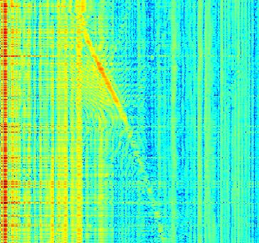
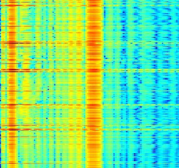
17 Results and further work The complete system was tested in the lab and in some green areas of UC Davis. Unfortunately during the short-term stay in UC Davis, it wasn t possible to generate an image with the SAR system that proves the correct performance of it. The images obtained show unidentified forms. An example of this is the following, Figure 2 shows a scene that was tried to be imaged and Figure 21 and Figure 22 show the result of capturing data twice along the rail and introducing the data to the RMA script in MATLAB. Figure 2

18 Figure 21 Figure 22 This could not be completed due to some unexpected delays occurred in the delivery of the components to build the rail. The research and correct implementation is still being worked in the CICESE as part of the thesis research and continuing with the work done in Davis. The results will be shared with Prof. Leo Liu in the future.
A Low-Power, High Sensitivity, X-Band Rail SAR Imaging System
 A Low-Power, High Sensitivity, X-Band Rail SAR Imaging System Gregory L. Charvat 1,, Leo C. Kempel 1, and Chris Coleman 2 1 Department of Electrical and Computer Engineering Michigan State University,
RF SENIOR DESIGN PROJECT REPORT
 EEC 134 Project Report 1 RF SENIOR DESIGN PROJECT REPORT EEC 134 Professor Xiaoquang Liu Team DMK Team members: Duyen Tran Khoa Huynh Michelle Lee Date: 5/25/2016 EEC 134 Project Report 2 RF SENIOR DESIGN
EEC 134 Final Report
 EEC 134 Final Report Team Falcon 9 Alejandro Venegas Marco Venegas Alexis Torres Gerardo Abrego Abstract: EEC 134 By Falcon 9 In the EEC 134 course the focus is on RF/microwave systems design. The main
EEC 134AB. Application Note. Radar System Design for RF. By: Yharo Torres. Group: Diode Hard 3. Fundamental Design of Radar:
 EEC 134AB Application Note Radar System Design for RF By: Yharo Torres Group: Diode Hard 3 Fundamental Design of Radar: The radar design we decided to go with for the quarter 2 design is one that is fundamentally
EEC 134 Project Report RF/Microwave System Design Fall - Winter 2016 Professor Liu. Team RF Eater Qun Xia Yueming Qiu Tianyi Gao Jiaming She
 EEC 134 Project Report RF/Microwave System Design Fall - Winter 2016 Professor Liu Team RF Eater Qun Xia Yueming Qiu Tianyi Gao Jiaming She Abstract This two quarters we work on a Frequency Modulated Continuous
EEC134 Application Note. FMCW Radar System Test. By Ghazanfar Abbas Alvi
 EEC134 Application Note FMCW Radar System Test By Ghazanfar Abbas Alvi April 12 th, 2016 Overview The system technology implemented is classified as frequency modulation continuous wave (FMCW) radar that
Project Report. Laptop Based Radar
 Project Report Laptop Based Radar Selected Topics in Microelectronics I (EE 680) (Spring Semester 2013) Submitted by: 1. Mirmehdi seyedesfahlan 2. Mohammad hossein Nemati 3. Efe Ozturk 4. Haq Nawaz 5.
RF Board Design. EEC 134 Application Note. Jo Han Yu
 EEC 134 Application Note Jo Han Yu EEC 134 Application Note RF Board Design Introduction The objective of this application note is to outline the process of designing system and PCB layout for RF board
S-Band 2.4GHz FMCW Radar
 S-Band 2.4GHz FMCW Radar Iulian Rosu, YO3DAC / VA3IUL, Filip Rosu, YO3JMK, http://qsl.net/va3iul A Radar detects the presence of objects and locates their position in space by transmitting electromagnetic
Frequency Modulated Continuous Wave Radar
 Frequency Modulated Continuous Wave Radar Albert Yeh Diana Nguyen Onyedikachi Okemiri Timothy Lau Teacher Assistants : Daniel Kuzmenko, Hao Wang, Songjie Bi Professor : Xiaoguang Leo Liu Course : EEC 134
Digital Signal Processing (DSP) Algorithms for CW/FMCW Portable Radar
 Algorithms for CW/FMCW Portable Radar") Digital Signal Processing (DSP) Algorithms for CW/FMCW Portable Radar Muhammad Zeeshan Mumtaz, Ali Hanif, Ali Javed Hashmi National University of Sciences and Technology (NUST), Islamabad, Pakistan Abstract
Digital Signal Processing (DSP) Algorithms for CW/FMCW Portable Radar Muhammad Zeeshan Mumtaz, Ali Hanif, Ali Javed Hashmi National University of Sciences and Technology (NUST), Islamabad, Pakistan Abstract
Optical Delay Line Application Note
 1 Optical Delay Line Application Note 1.1 General Optical delay lines system (ODL), incorporates a high performance lasers such as DFBs, optical modulators for high operation frequencies, photodiodes,
RF/IF Terminology and Specs
 RF/IF Terminology and Specs Contributors: Brad Brannon John Greichen Leo McHugh Eamon Nash Eberhard Brunner 1 Terminology LNA - Low-Noise Amplifier. A specialized amplifier to boost the very small received
A Unique Approach to Frequency-Modulated Continuous-Wave Radar Design
 Electromagnetics Research Group G.L. Charvat, L.C. Kempel, Michigan State University AMTA 2004 1 Overview of Presentation Principles of Frequency-Modulated Continuous-Wave (FMCW) Radar The unique approach
Windfreak Technologies SynthHD v1.4 Preliminary Data Sheet v0.2b
 Windfreak Technologies SynthHD v1.4 Preliminary Data Sheet v0.2b $1299.00US 54 MHz 13.6 GHz Dual Channel RF Signal Generator Features Open source Labveiw GUI software control via USB Run hardware functions
Radar Shield System Design
 University of California, Davis EEC 193 Final Project Report Radar Shield System Design Lit Po Kwong: lkwong853@gmail.com Yuyang Xie: szyuyxie@gmail.com Ivan Lee: yukchunglee@hotmail.com Ri Liang: joeliang914@gmail.com
Synthetic Aperture Radar (SAR) Imaging using Global Back Projection (GBP) Algorithm For Airborne Radar Systems
 Imaging using Global Back Projection (GBP) Algorithm For Airborne Radar Systems") Proc. of Int. Conf. on Current Trends in Eng., Science and Technology, ICCTEST Synthetic Aperture Radar (SAR) Imaging using Global Back Projection (GBP) Algorithm For Airborne Radar Systems Kavitha T M
Proc. of Int. Conf. on Current Trends in Eng., Science and Technology, ICCTEST Synthetic Aperture Radar (SAR) Imaging using Global Back Projection (GBP) Algorithm For Airborne Radar Systems Kavitha T M
Real-Time Through-Wall Imaging Using an Ultrawideband Multiple-Input Multiple-Output (MIMO) Phased-Array Radar System
 Phased-Array Radar System") Real-Time Through-Wall Imaging Using an Ultrawideband Multiple-Input Multiple-Output (MIMO) Phased-Array Radar System G. L. Charvat, T. S. Ralston, and J. E. Peabody Aerospace Sensor Technology Group This
Real-Time Through-Wall Imaging Using an Ultrawideband Multiple-Input Multiple-Output (MIMO) Phased-Array Radar System G. L. Charvat, T. S. Ralston, and J. E. Peabody Aerospace Sensor Technology Group This
ELEC RADAR FRONT-END SUMMARY
 ELEC Radar Front-End is designed for FMCW (including CW) radar application. The output frequency of each RX provides range, speed, and amplitude information to DSP. It will detect target azimuth angle
A LOW-POWER, REAL-TIME, S-BAND RADAR IMAGING SYSTEM
 A LOW-POWER, REAL-TIME, S-BAND RADAR IMAGING SYSTEM Gregory L. Charvat, Leo C. Kempel, and Edward J. Rothwell Dept. of Electrical and Computer Engineering, 2120 Engineering Building, Michigan State University,
Design Implementation Description for the Digital Frequency Oscillator
 Appendix A Design Implementation Description for the Frequency Oscillator A.1 Input Front End The input data front end accepts either analog single ended or differential inputs (figure A-1). The input
The Discussion of this exercise covers the following points:
 Exercise 3-2 Frequency-Modulated CW Radar EXERCISE OBJECTIVE When you have completed this exercise, you will be familiar with FM ranging using frequency-modulated continuous-wave (FM-CW) radar. DISCUSSION
AC LAB ECE-D ecestudy.wordpress.com
 PART B EXPERIMENT NO: 1 AIM: PULSE AMPLITUDE MODULATION (PAM) & DEMODULATION DATE: To study Pulse Amplitude modulation and demodulation process with relevant waveforms. APPARATUS: 1. Pulse amplitude modulation
David Fisher EEC 134 Application Note
 David Fisher EEC 134 Application Note RF System Design and Component Selection for a FMCW Radar System Introduction Since their initial development in the first half of the twentieth century, radar systems
Exercise 1: RF Stage, Mixer, and IF Filter
 SSB Reception Analog Communications Exercise 1: RF Stage, Mixer, and IF Filter EXERCISE OBJECTIVE DISCUSSION On the circuit board, you will set up the SSB transmitter to transmit a 1000 khz SSB signal
Unprecedented wealth of signals for virtually any requirement
 Dual-Channel Arbitrary / Function Generator R&S AM300 Unprecedented wealth of signals for virtually any requirement The new Dual-Channel Arbitrary / Function Generator R&S AM300 ideally complements the
TestData Summary of 5.2GHz WLAN Direct Conversion RF Transceiver Board
 Page 1 of 16 ========================================================================================= TestData Summary of 5.2GHz WLAN Direct Conversion RF Transceiver Board =========================================================================================
Receiver Architecture
 Receiver Architecture Receiver basics Channel selection why not at RF? BPF first or LNA first? Direct digitization of RF signal Receiver architectures Sub-sampling receiver noise problem Heterodyne receiver
Notes on Experiment #1
 Notes on Experiment #1 Bring graph paper (cm cm is best) From this week on, be sure to print a copy of each experiment and bring it with you to lab. There will not be any experiment copies available in
Frequency-Modulated Continuous-Wave Radar (FM-CW Radar)
") Frequency-Modulated Continuous-Wave Radar (FM-CW Radar) FM-CW radar (Frequency-Modulated Continuous Wave radar = FMCW radar) is a special type of radar sensor which radiates continuous transmission power
Frequency-Modulated Continuous-Wave Radar (FM-CW Radar) FM-CW radar (Frequency-Modulated Continuous Wave radar = FMCW radar) is a special type of radar sensor which radiates continuous transmission power
The Phased Array Feed Receiver System : Linearity, Cross coupling and Image Rejection
 The Phased Array Feed Receiver System : Linearity, Cross coupling and Image Rejection D. Anish Roshi 1,2, Robert Simon 1, Steve White 1, William Shillue 2, Richard J. Fisher 2 1 National Radio Astronomy
Characteristics of an Optical Delay Line for Radar Testing
 Naval Research Laboratory Washington, DC 20375-5320 NRL/MR/5306--16-9654 Characteristics of an Optical Delay Line for Radar Testing Mai T. Ngo AEGIS Coordinator Office Radar Division Jimmy Alatishe SukomalTalapatra
Lab Exercise PN: Phase Noise Measurement - 1 -
 Lab Exercise PN: Phase Noise Measurements Phase noise is a critical specification for oscillators used in applications such as Doppler radar and synchronous communications systems. It is tricky to measure
Receiver Design. Prof. Tzong-Lin Wu EMC Laboratory Department of Electrical Engineering National Taiwan University 2011/2/21
 Receiver Design Prof. Tzong-Lin Wu EMC Laboratory Department of Electrical Engineering National Taiwan University 2011/2/21 MW & RF Design / Prof. T. -L. Wu 1 The receiver mush be very sensitive to -110dBm
A DSP IMPLEMENTED DIGITAL FM MULTIPLEXING SYSTEM
 A DSP IMPLEMENTED DIGITAL FM MULTIPLEXING SYSTEM Item Type text; Proceedings Authors Rosenthal, Glenn K. Publisher International Foundation for Telemetering Journal International Telemetering Conference
Design and implementation of a C-Band transceiver for the South African Synthetic Aperture Radar (SASAR II) project
 project") Design and implementation of a C-Band transceiver for the South African Synthetic Aperture Radar (SASAR II) project Jonathan Michael Ward A project report submitted to the Department of Electrical Engineering,
Design and implementation of a C-Band transceiver for the South African Synthetic Aperture Radar (SASAR II) project Jonathan Michael Ward A project report submitted to the Department of Electrical Engineering,
Modulation is the process of impressing a low-frequency information signal (baseband signal) onto a higher frequency carrier signal
 onto a higher frequency carrier signal") Modulation is the process of impressing a low-frequency information signal (baseband signal) onto a higher frequency carrier signal Modulation is a process of mixing a signal with a sinusoid to produce
Modulation is the process of impressing a low-frequency information signal (baseband signal) onto a higher frequency carrier signal Modulation is a process of mixing a signal with a sinusoid to produce
Features. = +25 C, Vdc = +12V
 Typical Applications The VCO Module is ideal for: Industrial/Medical Equipment Test & Measurement Equipment Military Radar, EW & ECM Lab Instrumentation Functional Diagram Electrical Specifications, T
Evaluation of Millimeter wave Radar using Stepped Multiple Frequency Complementary Phase Code modulation
 Evaluation of Millimeter wave Radar using Stepped Multiple Frequency Complementary Phase Code modulation Masato WATANABE and Takayuki INABA Graduate School of Electro-Communications, The University of
DS H01 DIGITAL SYNTHESIZER MODULE SYSTEM SOLUTIONS. Features Applications 174 x 131 x 54 mm. Technical Description
 DS H01 The DS H01 is a high performance dual digital synthesizer with wide output bandwidth specially designed for Defense applications where generation of wideband ultra-low noise signals along with very
Design of a metal detector
 FACULTY OF ENGINEERING AND SUSTAINABLE DEVELOPMENT Department of Electronics, Mathematics and Natural Sciences Design of a metal detector Ammar Haider 2018 Student thesis, Advanced level (Master degree,
An Interactive Radar Demonstration for Children
 An Interactive Radar Demonstration for Children Team 5: Nur Syuhada Zakaria Andy Myrick Steve Hughey Andrew Renton Sponsor: MIT Lincoln Laboratory Facilitator: Dr. Radha Outline Introduction and goals
Exercise 1-4. The Radar Equation EXERCISE OBJECTIVE DISCUSSION OUTLINE DISCUSSION OF FUNDAMENTALS
 Exercise 1-4 The Radar Equation EXERCISE OBJECTIVE When you have completed this exercise, you will be familiar with the different parameters in the radar equation, and with the interaction between these
Case Study: and Test Wireless Receivers
 Case Study: Using New Technologies to Design and Test Wireless Receivers Agenda Architecture of a receiver Basic GPS Receiver Measurements Case Study 1: GPS Simulation How Testing Works Simulation vs.
Radio Receivers. Al Penney VO1NO
 Radio Receivers Al Penney VO1NO Role of the Receiver The Antenna must capture the radio wave. The desired frequency must be selected from all the EM waves captured by the antenna. The selected signal is
DESCRIPTION OF THE OPERATION AND CALIBRATION OF THE MILLIMETER I/Q PHASE BRIDGE-INTERFEROMETER
 DESCRIPTION OF THE OPERATION AND CALIBRATION OF THE MILLIMETER I/Q PHASE BRIDGE-INTERFEROMETER Overview of Interferometer Operation The block diagram of the I/Q Phase Bridge-Interferometer is shown below
Broadband Millimeter-wave FMCW Radar for Imaging of Humans
 Broadband Millimeter-wave FMCW Radar for Imaging of Humans A. Dallinger, S. Schelkshorn, J. Detlefsen Technische Universität München, Lehrstuhl für Hochfrequenztechnik, Fachgebiet Hochfrequente Felder
60 GHz Receiver (Rx) Waveguide Module
 Waveguide Module") The PEM is a highly integrated millimeter wave receiver that covers the GHz global unlicensed spectrum allocations packaged in a standard waveguide module. Receiver architecture is a double conversion,
The PEM is a highly integrated millimeter wave receiver that covers the GHz global unlicensed spectrum allocations packaged in a standard waveguide module. Receiver architecture is a double conversion,
EEC134 Final Report. Cameron Vossoughi PCB Design. Christian Hernandez RF Design. Kevin Matsui RF Design and PCB Assembly
 EEC134 Final Report Christian Hernandez RF Design Kevin Matsui RF Design and PCB Assembly Cameron Vossoughi PCB Design Colin Lewis PCB Assembly and Debugging I. SYSTEM DESIGN Our main priorities for our
60 GHz RX. Waveguide Receiver Module. Features. Applications. Data Sheet V60RXWG3. VubIQ, Inc
 GHz RX VRXWG Features Complete millimeter wave receiver WR-, UG-8/U flange Operates in the to GHz unlicensed band db noise figure Up to.8 GHz modulation bandwidth I/Q analog baseband interface Integrated
THE USE OF A FREQUENCY DOMAIN STEPPED FREQUENCY TECHNIQUE TO OBTAIN HIGH RANGE RESOLUTION ON THE CSIR X-BAND SAR SYSTEM
 THE USE OF A FREQUENCY DOMAIN STEPPED FREQUENCY TECHNIQUE TO OBTAIN HIGH RANGE RESOLUTION ON THE CSIR X-BAND SAR SYSTEM Willie Nel, CSIR Defencetek, Pretoria, South Africa Jan Tait, CSIR Defencetek, Pretoria,
Model 855 RF / Microwave Signal Generator
 Features Very low phase noise Fast switching Phase coherent switching option 2 to 8 phase coherent outputs USB, LAN, GPIB interfaces Applications Radar simulation Quantum computing High volume automated
Lecture 6 SIGNAL PROCESSING. Radar Signal Processing Dr. Aamer Iqbal Bhatti. Dr. Aamer Iqbal Bhatti
 Lecture 6 SIGNAL PROCESSING Signal Reception Receiver Bandwidth Pulse Shape Power Relation Beam Width Pulse Repetition Frequency Antenna Gain Radar Cross Section of Target. Signal-to-noise ratio Receiver
Simulating and Testing of Signal Processing Methods for Frequency Stepped Chirp Radar
 Test & Measurement Simulating and Testing of Signal Processing Methods for Frequency Stepped Chirp Radar Modern radar systems serve a broad range of commercial, civil, scientific and military applications.
Advanced Digital Receiver
 Advanced Digital Receiver MI-750 FEATURES Industry leading performance with up to 4 M samples per second 135 db dynamic range and -150 dbm sensitivity Optimized timing for shortest overall test time Wide
TBSI W32 System Manual Version 3.0
 TBSI W32 System Manual Version 3.0 Triangle BioSystems International 2224 Page Rd. Suite 108 Durham, NC 27703 Phone: (919) 361-2663 Fax: (919) 544-3061 www.trianglebiosystems.com Contents 32 CHANNEL WIRELESS
UNIT-3. Electronic Measurements & Instrumentation
 UNIT-3 1. Draw the Block Schematic of AF Wave analyzer and explain its principle and Working? ANS: The wave analyzer consists of a very narrow pass-band filter section which can Be tuned to a particular
Proceedings of the ASME th International Conference on Ocean, Offshore and Arctic Engineering OMAE2017 June 25-30, 2017, Trondheim, Norway
 Proceedings of the ASME 2017 36th International Conference on Ocean, Offshore and Arctic Engineering OMAE2017 June 25-30, 2017, Trondheim, Norway OMAE2017-61264 A UAV SAR PROTOTYPE FOR MARINE AND ARCTIC
A LOW-COST SOFTWARE-DEFINED TELEMETRY RECEIVER
 A LOW-COST SOFTWARE-DEFINED TELEMETRY RECEIVER Michael Don U.S. Army Research Laboratory Aberdeen Proving Grounds, MD ABSTRACT The Army Research Laboratories has developed a PCM/FM telemetry receiver using
Ka Band Radar Transceiver
 Ka Band Radar Transceiver Ka-Band Radar Transceiver with Integrated LO Source Homodyne System with Integrated TX & LO Multiplied VCO with Phase noise
and GHz. ECE Radiometer. Technical Description and User Manual
 E-mail: sales@elva-1.com http://www.elva-1.com 26.5-40 and 76.5-90 GHz ECE Radiometer Technical Description and User Manual November 2008 Contents 1. Introduction... 3 2. Parameters and specifications...
ANALOG COMMUNICATION
 ANALOG COMMUNICATION TRAINING LAB Analog Communication Training Lab consists of six kits, one each for Modulation (ACL-01), Demodulation (ACL-02), Modulation (ACL-03), Demodulation (ACL-04), Noise power
On the Design of Software and Hardware for a WSN Transmitter
 16th Annual Symposium of the IEEE/CVT, Nov. 19, 2009, Louvain-La-Neuve, Belgium 1 On the Design of Software and Hardware for a WSN Transmitter Jo Verhaevert, Frank Vanheel and Patrick Van Torre University
RFID Reader Frontends for a Dual-Frequency (13 MHz and 868 MHz) Rapid Prototyping Environment
 Rapid Prototyping Environment") RFID Reader Frontends for a Dual-Frequency (13 MHz and 868 MHz) Rapid Prototyping Environment Robert Langwieser, Michael Fischer and Prof. Dr. Arpad L. Scholtz Vienna University of Technology www.tuwien.ac.at
RFID Reader Frontends for a Dual-Frequency (13 MHz and 868 MHz) Rapid Prototyping Environment Robert Langwieser, Michael Fischer and Prof. Dr. Arpad L. Scholtz Vienna University of Technology www.tuwien.ac.at
Smart Energy Solutions for the Wireless Home
 Smart Energy Solutions for the Wireless Home Advanced Metering Infrastructure (AMI) ZigBee (IEEE 802.15.4) Wireless Local Area Networks (WLAN) Industrial and Home Control Plug-in Hybrid Electric Vehicles
Feedback Loop Canceller Circuit
 Feedback Loop Canceller Circuit Bachelor Thesis Ahmad Bader Ibrahim Obeidat Supervised by Prof. Dr.-Ing. Klaus Solbach 17.11.2014 Outline: 1 Motivation 2 Circuit description 3 Tasks and objectives 4 Active
EXHIBIT 7: MEASUREMENT PROCEDURES Pursuant 47 CFR 2.947
 EXHIBIT 7: MEASUREMENT PROCEDURES Pursuant 47 CFR 2.947 7.1 RF Power -- Pursuant to 47 CFR 2.947(c) Method of Conducted Output Power Measurement: Adaptation of TIA/EIA-603-A clause 2.2.1 for Pulsed Measurements
Developing a Generic Software-Defined Radar Transmitter using GNU Radio
 Developing a Generic Software-Defined Radar Transmitter using GNU Radio A thesis submitted in partial fulfilment of the requirements for the degree of Master of Sciences (Defence Signal Information Processing)
Signal Processing and Display of LFMCW Radar on a Chip
 Signal Processing and Display of LFMCW Radar on a Chip Abstract The tremendous progress in embedded systems helped in the design and implementation of complex compact equipment. This progress may help
Software Defined Radio in Ham Radio Dennis Silage K3DS TS EPA Section ARRL
 Software Defined Radio in Ham Radio Dennis Silage K3DS silage@arrl.net TS EPA Section ARRL TUARC K3TU SDR in HR The crystal radio was once a simple introduction to radio electronics and Amateur Radio.
ECE 4670 Spring 2014 Lab 1 Linear System Characteristics
 ECE 4670 Spring 2014 Lab 1 Linear System Characteristics 1 Linear System Characteristics The first part of this experiment will serve as an introduction to the use of the spectrum analyzer in making absolute
DEPARTMENT OF INFORMATION ENGINEERING. Test No. 1. Introduction to Scope Measurements. 1. Correction. Term Correction. Term...
 2. Correction. Correction Report University of Applied Sciences Hamburg Group No : DEPARTMENT OF INFORMATION ENGINEERING Laboratory for Instrumentation and Measurement L: in charge of the report Test No.
Measurement Setup for Phase Noise Test at Frequencies above 50 GHz Application Note
 Measurement Setup for Phase Noise Test at Frequencies above 50 GHz Application Note Products: R&S FSWP With recent enhancements in semiconductor technology the microwave frequency range beyond 50 GHz becomes
GENERATION OF SIGNALS USING LABVIEW FOR MAGNETIC COILS WITH POWER AMPLIFIERS
 GENERATION OF SIGNALS USING LABVIEW FOR MAGNETIC COILS WITH POWER AMPLIFIERS Ashmi G V 1, Meena M S 2 1 ER&DCI-IT, Centre for Development of Advanced Computing, Thiruvananthapuram(India) 2 LAMP Group,
A COMPACT, AGILE, LOW-PHASE-NOISE FREQUENCY SOURCE WITH AM, FM AND PULSE MODULATION CAPABILITIES
 A COMPACT, AGILE, LOW-PHASE-NOISE FREQUENCY SOURCE WITH AM, FM AND PULSE MODULATION CAPABILITIES Alexander Chenakin Phase Matrix, Inc. 109 Bonaventura Drive San Jose, CA 95134, USA achenakin@phasematrix.com
SynthNV - Signal Generator / Power Detector Combo
 SynthNV - Signal Generator / Power Detector Combo The Windfreak SynthNV is a 34.4MHz to 4.4GHz software tunable RF signal generator controlled and powered by a PC running Windows XP, Windows 7, or Android
12kHz LIF Converter V2.43 9Mhz version
 12kHz LIF Converter V2.43 9Mhz version Please Note: This document supersedes all previously released documents and drawings on the LIF subject. This is the latest and most up-to-date document at this time.
LUXONDES. See the electromagnetic waves. Product 2018 / 19
 LUXONDES See the electromagnetic waves Product 2018 / 19 RADIO WAVES DISPLAY - 400 The Luxondes radiofrequency to optical conversion panel directly displays the ambient EM-field or the radiation of a transmitting
Instrumentation Receiver: Analog Signal Processing for a DSP World. Rick Campbell Portland State University
 Instrumentation Receiver: Analog Signal Processing for a DSP World Rick Campbell Portland State University Tonight s Talk discusses 3 questions: What is an Instrumentation Receiver? How does Rick design
Microwave Metrology -ECE 684 Spring Lab Exercise I&Q.v3: I&Q Time and Frequency Domain Measurements
 Lab Exercise I&Q.v3: I&Q Time and Frequency Domain Measurements In this lab exercise you will perform measurements both in time and in frequency to establish the relationship between these two dimension
K-MC2 RADAR TRANSCEIVER Replaced by K-MC3 Datasheet. Features. Applications. Description. Blockdiagram
 Features 24 GHz short range transceiver 90MHz sweep FM input High sensitivity, integrated RF/IF amplifier Dual 62 patch narrow beam antenna Buffered, gain adjustable I/Q IF outputs Additional DC IF outputs
Contents. ZT530PCI & PXI Specifications. Arbitrary Waveform Generator. 16-bit, 400 MS/s, 2 Ch
 ZT530PCI & PXI Specifications Arbitrary Waveform Generator 16-bit, 400 MS/s, 2 Ch Contents Outputs... 2 Digital-to-Analog Converter (DAC)... 3 Internal DAC Clock... 3 Spectral Purity... 3 External DAC
RECOMMENDATION ITU-R SM Method for measurements of radio noise
 Rec. ITU-R SM.1753 1 RECOMMENDATION ITU-R SM.1753 Method for measurements of radio noise (Question ITU-R 1/45) (2006) Scope For radio noise measurements there is a need to have a uniform, frequency-independent
Keysight Technologies Pulsed Antenna Measurements Using PNA Network Analyzers
 Keysight Technologies Pulsed Antenna Measurements Using PNA Network Analyzers White Paper Abstract This paper presents advances in the instrumentation techniques that can be used for the measurement and
DEPARTMENT OF ELECTRONIC ENGINEERING PRACTICAL MANUAL CONTROL SYSTEMS 3 CSYS 302
 Name: Student number: Mark: DEPARTMENT OF ELECTRONIC ENGINEERING PRACTICAL MANUAL CONTROL SYSTEMS 3 (Process Instrumentation and Mechatronics) CSYS 30 Latest Revision: Semester 1-016 1 INTRODUCTION The
Initial ARGUS Measurement Results
 Initial ARGUS Measurement Results Grant Hampson October 8, Introduction This report illustrates some initial measurement results from the new ARGUS system []. Its main focus is on simple measurements of
MICROWAVE MICROWAVE TRAINING BENCH COMPONENT SPECIFICATIONS:
 Microwave section consists of Basic Microwave Training Bench, Advance Microwave Training Bench and Microwave Communication Training System. Microwave Training System is used to study all the concepts of
Radio Frequency Electronics (RFE)
") Radio Frequency Electronics (RFE) by Prof. Dr.rer.nat. Dr.h.c. Manfred Thumm 5th Edition: 2011 Forschungszentrum Karlsruhe in der Helmholtz - Gemeinschaft Universität Karlsruhe (TH) Research University
Radio Frequency Electronics (RFE) by Prof. Dr.rer.nat. Dr.h.c. Manfred Thumm 5th Edition: 2011 Forschungszentrum Karlsruhe in der Helmholtz - Gemeinschaft Universität Karlsruhe (TH) Research University
Advanced RF Measurements You Didn t Know Your Oscilloscope Could Make. Brad Frieden Philip Gresock
 Advanced RF Measurements You Didn t Know Your Oscilloscope Could Make Brad Frieden Philip Gresock Agenda RF measurement challenges Oscilloscope platform overview Typical RF characteristics Bandwidth vs.
A Microwave Reflectometer Prototype for Detection of Body Through the Rubble of Collapsed Buildings
 Advances in Science, Technology and Engineering Systems Journal Vol. 2, No. 3, 1092-1106 (2017) www.astesj.com Special Issue on Recent Advances in Engineering Systems ASTESJ ISSN: 2415-6698 A Microwave
Scalable Front-End Digital Signal Processing for a Phased Array Radar Demonstrator. International Radar Symposium 2012 Warsaw, 24 May 2012
 Scalable Front-End Digital Signal Processing for a Phased Array Radar Demonstrator F. Winterstein, G. Sessler, M. Montagna, M. Mendijur, G. Dauron, PM. Besso International Radar Symposium 2012 Warsaw,
Contents. CALIBRATION PROCEDURE NI PXIe-5668R 14 GHz and 26.5 GHz Signal Analyzer
 CALIBRATION PROCEDURE NI PXIe-5668R 14 GHz and 26.5 GHz Signal Analyzer This document contains the verification procedures for the National Instruments PXIe-5668R (NI 5668R) vector signal analyzer (VSA)
Microwave. Accessories for Microwave Scalar and System Analyzers
 Microwave Accessories for Microwave Scalar and System Analyzers The following optional accessories are designed for use with the 6200B series of Microwave Test Sets, the 6820 series Scalar Analyzers and
Heterodyne Sweeping Radiometer
 46 Robezu str. LV-1004 Riga, Latvia Fax: +371-7-065102 Mm-wave Division in St. Petersburg, Russia Fax: +7-812- 326-10-60 Tel: +7-812-326-59-24 E-mail: ivanovph@nnz.ru Heterodyne Sweeping Radiometer Operation
DEPARTMENT OF THE ARMY TECHNICAL BULLETIN CALIBRATION PROCEDURE FOR SHF SIGNAL GENERATOR AN/USM-47 (HEWLETT-PACKARD MODEL 626A) (NSN )
 (NSN )") DEPARTMENT OF THE ARMY TECHNICAL BULLETIN CALIBRATION PROCEDURE FOR SHF SIGNAL GENERATOR AN/USM-47 (HEWLETT-PACKARD MODEL 626A) (NSN 6625-00-455-6917) Headquarters, Department of the Army, Washington,
DEPARTMENT OF THE ARMY TECHNICAL BULLETIN CALIBRATION PROCEDURE FOR SHF SIGNAL GENERATOR AN/USM-47 (HEWLETT-PACKARD MODEL 626A) (NSN 6625-00-455-6917) Headquarters, Department of the Army, Washington,
RADIO RECEIVERS ECE 3103 WIRELESS COMMUNICATION SYSTEMS
 RADIO RECEIVERS ECE 3103 WIRELESS COMMUNICATION SYSTEMS FUNCTIONS OF A RADIO RECEIVER The main functions of a radio receiver are: 1. To intercept the RF signal by using the receiver antenna 2. Select the
DR-TRC105-EV Evaluation Kit. User s Guide
 DR-TRC105-EV Evaluation Kit User s Guide DR-TRC105-304-EV DR-TRC105-315-EV DR-TRC105-345-EV DR-TRC105-372-EV DR-TRC105-390-EV DR-TRC105-403-EV DR-TRC105-434-EV DR-TRC105-450-EV 2010-2015 by Murata Electronics
SERIES PLS PHASE LOCKED SYNTHESIZER. FEATURES: Small Size, Low Cost, Simple to use Low Phase Noise Auto-sensing Internal or External 10MHz Reference
 PHASE LOCKED SYNTHESIZER FEATURES: Small Size, Low Cost, Simple to use Low Phase Noise Auto-sensing Internal or External 10MHz Reference Can be utilized as a synthesizer, or a fixed frequency oscillator
Radar System Design Considerations -- System Modeling Findings (MOS-AK Conference Hangzhou 2017)
") Radar System Design Considerations -- System Modeling Findings (MOS-AK Conference Hangzhou 2017) Silicon Radar GmbH Im Technologiepark 1 15236 Frankfurt (Oder) Germany Outline 1 Introduction to Short Distance
Radar System Design Considerations -- System Modeling Findings (MOS-AK Conference Hangzhou 2017) Silicon Radar GmbH Im Technologiepark 1 15236 Frankfurt (Oder) Germany Outline 1 Introduction to Short Distance
USER OPERATION AND MAINTENANCE MANUAL
 46 Robezu str. LV-1004 Riga Latvia Phone: +371-7-065-100, Fax: +371-7-065-102 Mm-wave Division in St. Petersburg, Russia Phone: +7-812-326-5924, Fax: +7-812-326-1060 USER OPERATION AND MAINTENANCE MANUAL