Rev. A ( /10) By: AY, SA, JB (OPAL-RT)
|
|
|
- Reynold Bond
- 5 years ago
- Views:
Transcription
 OPAL-RT Technologies reserves")


1 Rev. A ( /10) By: AY, SA, JB (OPAL-RT) OPAL-RT Technologies reserves all rights in this document and in the information contained herein. Reproduction, use or disclosure to third parties without express authority is strictly forbidden.
2 A. Solar Power Conditioner Using a Zigzag-Connected Chopper Converter (Public) 1) Circuit 2) Time step Requirement 3) Test Results and Accuracy 4) Possible Solutions 5) Typical Model Separation 6) Real time simulation performance of the conditioner system 7) References Copyright (C) OPAL-RT Technologies 2
3 HIL Simulator of Solar Power Conditioner Copyright (C) OPAL-RT Technologies 3
4 Solar Power Conditioner Using a Zigzag-Connected Chopper Converter Copyright (C) OPAL-RT Technologies 4
")

5 Refer to reference (1) Copyright (C) OPAL-RT Technologies 5
6 The circuit was simulated: With PLECS With Simulink, SimPowerSystems (SPS) With Simulink, SimPowerSystems, with ARTEMIS, and TSB blocks for power converters Compared Simulation accuracy and Speed Copyright (C) OPAL-RT Technologies 6
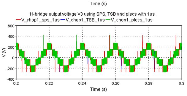
7 The simulation of PLECS, SPS, and TSB models showed that the waveforms exactly the same at very small time-step (1 us) Results are given on the next 3 slides. Therefore, in following tests, the model SPS at 1 us was taken as reference for the comparison. Copyright (C) OPAL-RT Technologies 7
8 Copyright (C) OPAL-RT Technologies 8
")
9 Copyright (C) OPAL-RT Technologies 9
10 Copyright (C) OPAL-RT Technologies 10
11 Copyright (C) OPAL-RT Technologies 11
12 Solar Power Conditioner Using a Zigzag-Connected Chopper Converter Copyright (C) OPAL-RT Technologies 12
13 The following tests were made on the circuit: SPS: at 1 us & 10 us TSB: at 1 us & 10 us PLECS: at 1 us & 10 us Copyright (C) OPAL-RT Technologies 13
14 If the (fixed) time step is increased then: both SPS and PLECS models loose their accuracy SPS-TSB model retains very good accuracy This is understandable because the simulation of switching converters in the circuit requires the use of interpolation when fixed step is used. And Interpolation is available only in OPAL-RT s TSB OPAL-RT studies show the following figures: With PLECS or SPS (no interpolation), the required step size needed for good accuracy is 1 to 2 % or the PWM period With TSB (with interpolation), the required step size is higher, % of PWM period 25 to 50 us is usually needed for other power system components Example PV conversion system switching at 20 khz (PWM cycle of 50 us), the required time step is: PLECS or SPS: 0.5 to 1 us OPAL-RT TSB: 5 to 10 us Solutions: Either decrease the time step to a very low value FPGA implementation Or increase the time step to a reasonable value CPU implementation using TSB converter models Copyright (C) OPAL-RT Technologies 14
15 Copyright (C) OPAL-RT Technologies 15
16 Copyright (C) OPAL-RT Technologies 16
17 Copyright (C) OPAL-RT Technologies 17
18 Solar Power Conditioner Using a Zigzag-Connected Chopper Converter Copyright (C) OPAL-RT Technologies 18
19 Bad results with non-characteristic unreal harmonics when no interpolation is used(plecs& SPS) Incorrect steady state results without interpolation(plecs& SPS) Good results when TSB blocks are used, because of interpolation of switching goodsteadystateresultswithtsb Bad staircase relation between Duty Cycle and steady-state output without interpolation (PLECS, SPS) and good linear relation with interpolation(tsb) Because TSB uses interpolation, it is able and does simulate dead-time effect(impossible with PLECS, or SPS) Copyright (C) OPAL-RT Technologies 19
20 100 V upper IG B T 1 m H 0.1 Ω lower IG BT load current The load current should be linearly dependent upon the chopper duty-cycle 150 Variation of Duty Cycle with step 0.1µs Load Current Vs Duty Cycle Load Current (A) TSB 0.1us PLECS 0.1us SPS 0.1us duty Cycle (%) Copyright (C) OPAL-RT Technologies 20
21 500 Variation of Duty Cycle with step 1µs Load Current Vs Duty Cycle 400 Load Current (A) TSB 1us 100 PLECS 1us SPS 1us duty Cycle (%) Load Current (A) Variation of Duty Cycle with step 10µs Load Current Vs Duty Cycle SPS_TSB_10us PLECS 10 SPS 10us Observation steady state results are totally incorrect & not acceptable without interpolation (PLECS or SPS), resulting in this staircase shape when duty is increased slowly TSB 10us PLECS 10us SPS 10us duty Cycle (%) Copyright (C) OPAL-RT Technologies 21
22 Solar Power Conditioner Using a Zigzag-Connected Chopper Converter Copyright (C) OPAL-RT Technologies 22
23 Mixed Simulation Targets Converters on FPGA, with OPAL- RT s converter model for FPGA Power component on CPU with PLECS or SPS All-CPU Simulation Converters model one CPU with OPAL-RT TSB Power component on a second CPU with PLECS or SPS FPGA CPU CPU 1 CPU 2 Copyright (C) OPAL-RT Technologies 23
24 Solar Power Conditioner Using a Zigzag-Connected Chopper Converter Copyright (C) OPAL-RT Technologies 24
25 Real time simulation performance of the PV conditioner developed in Matlab using OPAL-RT software platform This real time simulation ran on a dual-xeon-based, 3.33 GHz and RT-LAB simulator with a time step of 10µs. The overall system was run using two CPUs core out of 12 processor cores available. The processors allocation and Real-Time Performance are summarized in Table bellow. CPUs Descript ions CPU 1: (10 µs) CPU 2: (10us) Components Content SS_PV_conditioner (complete system in slide 5) SM_PV_conditioner (controller) Model Calculation Time 2.5 µs 1 µs Minimu m time step Accelera tion factor 5 µs 23 Copyright (C) OPAL-RT Technologies 25
26 Real time simulation performance of the PV conditioner developed in PLECS A PLECS circuit cannot contain more than 1024 = 2 10 possible topologies[2] which is equivalent to 10 switches per PLECS circuit. The solution of this problem is to divide the system into a number of PLECS sub-circuits in order to reduce the number of switches to less than 10 switches per PLECS. The other solution is to increase the possible topologies by PLECS Company. The PV conditioner given in slide 5 was separated into two PLECS circuits. Each circuit contains one of the two phases of the PV conditioner. This separation introduces some delays to connect the two PLECS circuits which can in some cases, affect the accuracy and the stability of the system depending on the number of delays introduced to separate the system. Copyright (C) OPAL-RT Technologies 26
27 Real time simulation performance of the PV conditioner developed in Matlab using PLECS This real time simulation ran on a dual-xeon-based, 3.33 GHz and RT-LAB simulator with a time step of 10µs. The overall system was run using two CPUs core out of 12 processor cores available. The processors allocation and Real-Time Performance are summarized in Table bellow. CPUs Descript ions CPU 1: (10 µs) CPU 2: (10us) Components Content SS_PV_conditioner (complete system in slide 5) SM_PV_conditioner (controller) Model Calculation Time 2.5 µs 1 µs Minimu m time step Accelera tion factor 5 µs 14 Copyright (C) OPAL-RT Technologies 27
28 1) Hideaki Fujita, A High-Efficiency Solar Power Conditioner Using a Zigzag-Connected Chopper Converter, The 2010 International Power Electronics Conference, Tokyo Institute of Technology, Tokyo, Japan. 2) PLECS Manual: Copyright (C) OPAL-RT Technologies 28
Hardware-In-the-Loop Simulation of Power Drives with RT-LAB
 Hardware-In-the-Loop Simulation of Power Drives with RT-LAB Christian Dufour, Simon Abourida, Jean Bélanger Opal-RT Technologies inc. 1751 Richardson, #2525 Montreal (Quebec), H3K 1G6, Canada {christian.dufour,
Fast solver to get steady-state waveforms for power converter design
 Fast solver to get steady-state waveforms for power converter design Guillaume Fontes, Power Design Technologies, France, guillaume.fontes@powerdesign.tech Regis Ruelland, Power Design Technologies, France,
Development of Dynamic Test Cases in OPAL-RT Real-time Power System Simulator
 Development of Dynamic Test Cases in OPAL-RT Real-time Power System Simulator Shiv Kumar Singh, Bibhu P. Padhy, Student Member, IEEE, S. Chakrabarti, Senior Member, IEEE, S.N. Singh, Senior Member, IEEE,
Closed Loop Single Phase Bidirectional AC to AC Buck Boost Converter for Power Quality Improvement
 International Journal of Engineering Research and Development e-issn: 2278-067X, p-issn: 2278-800X, www.ijerd.com Volume 7, Issue 11 (July 2013), PP. 35-42 Closed Loop Single Phase Bidirectional AC to
IMPROVING THE VOLTAGE GAIN OF DC- DC BOOST CONVERTER BY COUPLED INDUCTOR
 IMPROVING THE VOLTAGE GAIN OF DC- DC BOOST CONVERTER BY COUPLED INDUCTOR YENISETTI NEELIMA 1 1 ASST PROF CJIT JANGAON. Abstract The high gain DC-DC converter with coupling inductor is design to boost low
Validation of Frequency- and Time-domain Fidelity of an Ultra-low Latency Hardware-in-the-Loop (HIL) Emulator
 Emulator") Validation of Frequency- and Time-domain Fidelity of an Ultra-low Latency Hardware-in-the-Loop (HIL) Emulator Elaina Chai, Ivan Celanovic Institute for Soldier Nanotechnologies Massachusetts Institute
Validation of Frequency- and Time-domain Fidelity of an Ultra-low Latency Hardware-in-the-Loop (HIL) Emulator Elaina Chai, Ivan Celanovic Institute for Soldier Nanotechnologies Massachusetts Institute
D-UPFC Application as the Series Power Device in the Massive Roof-top PVs and Domestic Loads
 Current Photovoltaic Research 4(4) 131-139 (2016) pissn 2288-3274 DOI:https://doi.org/10.21218/CPR.2016.4.4.131 eissn 2508-125X D-UPFC Application as the Series Power Device in the Massive Roof-top PVs
Current Rebuilding Concept Applied to Boost CCM for PF Correction
 Current Rebuilding Concept Applied to Boost CCM for PF Correction Sindhu.K.S 1, B. Devi Vighneshwari 2 1, 2 Department of Electrical & Electronics Engineering, The Oxford College of Engineering, Bangalore-560068,
Chapter 3 : Closed Loop Current Mode DC\DC Boost Converter
 Chapter 3 : Closed Loop Current Mode DC\DC Boost Converter 3.1 Introduction DC/DC Converter efficiently converts unregulated DC voltage to a regulated DC voltage with better efficiency and high power density.
10 pf ~ 32 pf or Series Resonance. ±3 ppm per year max. -55 /+125 C OTHER PARAMETERS ARE AVAILABLE ON REQUEST / CREATE HERE YOUR SPECIFICATION
 SMD QUARTZ CRYSTAL SERIES SMD0507 (2 pad housing 7.0x5.0mm) Please do not use this housing for new design. Please use SMD0507/4 housing FEATURES + Large frequency spectrum available + Do not use for new
Grid Connected photovoltaic system based on Chain cell converter Using Simulink
 Grid Connected photovoltaic system based on Chain cell converter Using Simulink Problem statement To prove Chain cell converter performance superior when compared with the traditional Pulse width modulation
A Unity Power Factor Boost Rectifier with a Predictive Capacitor Model for High Bandwidth DC Bus Voltage Control
 A Unity Power Factor Boost Rectifier with a Predictive Capacitor Model for High Bandwidth DC Bus Voltage Control Peter Wolfs Faculty of Sciences, Engineering and Health Central Queensland University, Rockhampton
Circuit Simulation for Solar Power Maximum Power Point Tracking with Different Buck-Boost Converter Topologies
 Circuit Simulation for Solar Power Maximum Power Point Tracking with Different Buck-Boost Converter Topologies Jaw-Kuen Shiau, Min-Yi Lee, Yu-Chen Wei, and Bo-Chih Chen Department of Aerospace Engineering,
Jawad Ali, Muhammad Iftikhar Khan, Khadim Ullah Jan
 International Journal of Scientific & Engineering Research, Volume 5, Issue 8,August-2014 664 New Operational Mode of Diode Clamped Multilevel Inverters for Pure Sinusoidal Output Jawad Ali, Muhammad Iftikhar
MMC (Modular Multilevel Converter)
") MMC (Modular Multilevel Converter) Lisbon September 29 2017 Susana Apiñániz Smart Grids Energy and environment Division Tecnalia susana.apinaniz@tecnalia.com INDEX 1. General information 2. Power sub-modules
MMC (Modular Multilevel Converter) Lisbon September 29 2017 Susana Apiñániz Smart Grids Energy and environment Division Tecnalia susana.apinaniz@tecnalia.com INDEX 1. General information 2. Power sub-modules
New Conceptual High Efficiency Sinewave PV Power Conditioner with Partially-Tracked Dual Mode Step-up DC-DC Converter
 IEEE PEDS 2015, Sydney, Australia 9 12 June 2015 New Conceptual High Efficiency Sinewave PV Power Conditioner with Partially-Tracked Dual Mode Step-up DC-DC Converter Koki Ogura Kawasaki Heavy Industries,
A Bi-directional Z-source Inverter for Electric Vehicles
 A Bi-directional Z-source Inverter for Electric Vehicles Makoto Yamanaka and Hirotaka Koizumi Tokyo University of Science 1-14-6 Kudankita, Chiyoda-ku Tokyo 102-0073 Japan Email: hosukenigou@ieee.org littlespring@ieee.org
CHAPTER 3 APPLICATION OF THE CIRCUIT MODEL FOR PHOTOVOLTAIC ENERGY CONVERSION SYSTEM
 63 CHAPTER 3 APPLICATION OF THE CIRCUIT MODEL FOR PHOTOVOLTAIC ENERGY CONVERSION SYSTEM 3.1 INTRODUCTION The power output of the PV module varies with the irradiation and the temperature and the output
Success Story. An innovative HIL Test Bench to Validate Embedded SOCOMEC Inverter Software
 An innovative HIL Test Bench to Validate Embedded SOCOMEC Inverter Software SOCOMEC is represented on 5 continents, either through direct affiliates or distributors. Thanks to its commitment to innovation,
CHAPTER 5 MODIFIED SINUSOIDAL PULSE WIDTH MODULATION (SPWM) TECHNIQUE BASED CONTROLLER
 TECHNIQUE BASED CONTROLLER") 74 CHAPTER 5 MODIFIED SINUSOIDAL PULSE WIDTH MODULATION (SPWM) TECHNIQUE BASED CONTROLLER 5.1 INTRODUCTION Pulse Width Modulation method is a fixed dc input voltage is given to the inverters and a controlled
74 CHAPTER 5 MODIFIED SINUSOIDAL PULSE WIDTH MODULATION (SPWM) TECHNIQUE BASED CONTROLLER 5.1 INTRODUCTION Pulse Width Modulation method is a fixed dc input voltage is given to the inverters and a controlled
CHAPTER 4 DESIGN OF CUK CONVERTER-BASED MPPT SYSTEM WITH VARIOUS CONTROL METHODS
 68 CHAPTER 4 DESIGN OF CUK CONVERTER-BASED MPPT SYSTEM WITH VARIOUS CONTROL METHODS 4.1 INTRODUCTION The main objective of this research work is to implement and compare four control methods, i.e., PWM
CHAPTER 3 CUK CONVERTER BASED MPPT SYSTEM USING ADAPTIVE PAO ALGORITHM
 52 CHAPTER 3 CUK CONVERTER BASED MPPT SYSTEM USING ADAPTIVE PAO ALGORITHM 3.1 INTRODUCTION The power electronics interface, connected between a solar panel and a load or battery bus, is a pulse width modulated
Three Phase PFC and Harmonic Mitigation Using Buck Boost Converter Topology
 Three Phase PFC and Harmonic Mitigation Using Buck Boost Converter Topology Riya Philip 1, Reshmi V 2 Department of Electrical and Electronics, Amal Jyothi College of Engineering, Koovapally, India 1,
Real-time Volt/Var Optimization Scheme for Distribution Systems with PV Integration
 Grid-connected Advanced Power Electronic Systems Real-time Volt/Var Optimization Scheme for Distribution Systems with PV Integration 02-15-2017 Presenter Name: Yan Chen (On behalf of Dr. Benigni) Outline
In this lab you will build a photovoltaic controller that controls a single panel and optimizes its operating point driving a resistive load.
 EE 155/255 Lab #3 Revision 1, October 10, 2017 Lab3: PV MPPT Photovoltaic cells are a great source of renewable energy. With the sun directly overhead, there is about 1kW of solar energy (energetic photons)
A Switched Boost Inverter Fed Three Phase Induction Motor Drive
 A Switched Boost Inverter Fed Three Phase Induction Motor Drive 1 Riya Elizabeth Jose, 2 Maheswaran K. 1 P.G. student, 2 Assistant Professor 1 Department of Electrical and Electronics engineering, 1 Nehru
Laboratory set-up for Real-Time study of Electric Drives with Integrated Interfaces for Test and Measurement
 Laboratory set-up for Real-Time study of Electric Drives with Integrated Interfaces for Test and Measurement Fong Mak, Ram Sundaram, Varun Santhaseelan, and Sunil Tandle Gannon University, mak001@gannon.edu,
Real-Time Power System Simulation:
 OPAL-RT Technologies Real-Time Power System Simulation: EMT vs. Phasor White Paper OPAL-RT Technologies Inc. White Paper: opwp150620-sa-reva Last update: 02 September 2016 By: Simon Abourida, Jean Bélanger,
CHAPTER 4 FUZZY BASED DYNAMIC PWM CONTROL
 47 CHAPTER 4 FUZZY BASED DYNAMIC PWM CONTROL 4.1 INTRODUCTION Passive filters are used to minimize the harmonic components present in the stator voltage and current of the BLDC motor. Based on the design,
CASCADED H-BRIDGE THREE-PHASE MULTILEVEL INVERTERS CONTROLLED BY MULTI-CARRIER SPWM DEDICATED TO PV
 CASCADED H-BRIDGE THREE-PHASE MULTILEVEL INVERTERS CONTROLLED BY MULTI-CARRIER SPWM DEDICATED TO PV 1 ABDELAZIZ FRI, 2 RACHID EL BACHTIRI, 3 ABDELAZIZ EL GHZIZAL 123 LESSI Lab, FSDM Faculty, USMBA University.
Dsp Sine Wave Generation
 Dsp Free PDF ebook Download: Dsp Download or Read Online ebook dsp sine wave generation in PDF Format From The Best User Guide Database Sine wave generation using IIR filter. Introduction.. There exists
Modeling and Simulation of a DC-DC Boost converter and its performance analysis based on various parameters
 Modeling and Simulation of a DC-DC Boost converter and its performance analysis based on various parameters 1 Poonam Verma, 2 Dr. M. K. Bhaskar, Surbhi Bhandari 3 1 PG Scholar, 2 Professor, 3 Assistant
A Real-Time Multi Electrical System Integrated Simulator (MESIS) for Validation and Testing of More Electric Aircraft (MEA) Equipment
 for Validation and Testing of More Electric Aircraft (MEA) Equipment") A Real-Time Multi Electrical System Integrated Simulator (MESIS) for Validation and Testing of More Electric Aircraft (MEA) Equipment M. Hicar (a), C. Fallaha (b) and J-N. Paquin (c) (a) Bombardier Aerospace,
A Real-Time Multi Electrical System Integrated Simulator (MESIS) for Validation and Testing of More Electric Aircraft (MEA) Equipment M. Hicar (a), C. Fallaha (b) and J-N. Paquin (c) (a) Bombardier Aerospace,
Single Phase AC Converters for Induction Heating Application
 Single Phase AC Converters for Induction Heating Application Neethu Salim 1, Benny Cherian 2, Geethu James 3 P.G. student, Mar Athanasius College of Engineering, Kothamangalam, Kerala, India 1 Professor,
CHAPTER 5 NOVEL CARRIER FUNCTION FOR FUNDAMENTAL FORTIFICATION IN VSI
 98 CHAPTER 5 NOVEL CARRIER FUNCTION FOR FUNDAMENTAL FORTIFICATION IN VSI 5.1 INTRODUCTION This chapter deals with the design and development of FPGA based PWM generation with the focus on to improve the
A Double Input DC to DC Buck-Boost Converter for Low Voltage Photovoltaic/Wind Systems
 International Journal of ChemTech Research CODEN( USA): IJCRGG ISSN : 0974-4290 Vol.5, No.2, pp 1016-1023, April-June 2013 ICGSEE-2013[14 th 16 th March 2013] International Conference on Global Scenario
UNISONIC TECHNOLOGIES CO., LTD
 U UNISONIC TECHNOLOGIES CO., LTD REGULATING PWM IC DESCRIPTION The UTC U is a pulse width modulator IC and designed for switching power supplies application to improve performance and reduce external parts
Data Sheet. Peak, CW & Average. Power Sensors. Taking performance to a new peak
 Data Sheet Peak, CW & Average Power Sensors Taking performance to a new peak Peak, CW & Average Power Sensors The overall performance of a power meter dependents on the power sensor employed. Boonton has
Self Lifted SEPIC-Cuk Combination Converter
 Self Lifted SEPIC-Cuk Combination Converter Anooja Shahul 1, Prof. Annie P Oommen 2, Prof. Benny Cherian 3 1 PG Scholar, 2,3 Professor, Department of Electrical and Electronics Engineering, Mar Athanasius
CONCLUSIONS AND SCOPE FOR FUTURE WORK
 Chapter 6 CONCLUSIONS AND SCOPE FOR FUTURE WORK 6.1 CONCLUSIONS Distributed generation (DG) has much potential to improve distribution system performance. The use of DG strongly contributes to a clean,
An Interleaved High-Power Fly back Inverter for Photovoltaic Applications
 An Interleaved High-Power Fly back Inverter for Photovoltaic Applications S.Sudha Merlin PG Scholar, Department of EEE, St.Joseph's College of Engineering, Semmencherry, Chennai, Tamil Nadu, India. ABSTRACT:
PA-AB 4Q POWER AMPLIFIER
 PA series is a real 4 quadrants AC+DC amplifier to test or simulate all kind of loads or generators with power, high dymamic, a low distortion and a large bandwidth. Our own high performance linear technology
Simulation of Perturb and Observe MPPT algorithm for FPGA
 Simulation of Perturb and Observe MPPT algorithm for FPGA Vinod Kumar M. P. 1 PG Scholar, Department of Electrical and Electronics Engineering, NMAMIT, Nitte, Udupi, India 1 ABSTRACT: The generation of
Generalized Multilevel Current-Source PWM Inverter with No-Isolated Switching Devices
 Generalized Multilevel Current-Source PWM Inverter with No-Isolated Switching Devices Suroso* (Nagaoka University of Technology), and Toshihiko Noguchi (Shizuoka University) Abstract The paper proposes
Bidirectional Ac/Dc Converter with Reduced Switching Losses using Feed Forward Control
 Bidirectional Ac/Dc Converter with Reduced Switching Losses using Feed Forward Control Lakkireddy Sirisha Student (power electronics), Department of EEE, The Oxford College of Engineering, Abstract: The
Design of Chopper Fed Z Source PWM Inverter
 Volume 119 No. 12 2018, 15165-15175 ISSN: 1314-3395 (on-line version) url: http://www.ijpam.eu ijpam.eu Design of Chopper Fed Z Source PWM Inverter 1 K. Vibha and 2 K. Sudha 1 Department of Electronics
DC Chopper. Prof. Dr. Fahmy El-khouly
 DC Chopper Prof. Dr. Fahmy El-khouly Definitions: The power electronic circuit which converts directly from dc to dc is called dc-to-dc converter or dc-chopper. Chopper is a dc to dc transformer: The input
SIMULATIONS WITH THE BOOST TOPOLOGY EE562: POWER ELECTRONICS I COLORADO STATE UNIVERSITY. Modified February 2006
 SIMULATIONS WITH THE BOOST TOPOLOGY EE562: POWER ELECTRONICS I COLORADO STATE UNIVERSITY Modified February 26 Page 1 of 24 PURPOSE: The purpose of this lab is to simulate the Boost converter using ORCAD
DIGITAL SIMULATION OF MULTILEVEL INVERTER BASED STATCOM
 DIGITAL SIMULATION OF MULTILEVEL INVERTER BASED STATCOM G.SUNDAR, S.RAMAREDDY Research Scholar, Bharath University Chenna Professor Jerusalam College of Engg. Chennai ABSTRACT This paper deals with simulation
CHAPTER 3 MODELLING OF PV SOLAR FARM AS STATCOM
 47 CHAPTER 3 MODELLING OF PV SOLAR FARM AS STATCOM 3.1 INTRODUCTION Today, we are mostly dependent on non renewable energy that have been and will continue to be a major cause of pollution and other environmental
CHAPTER-III MODELING AND IMPLEMENTATION OF PMBLDC MOTOR DRIVE
 CHAPTER-III MODELING AND IMPLEMENTATION OF PMBLDC MOTOR DRIVE 3.1 GENERAL The PMBLDC motors used in low power applications (up to 5kW) are fed from a single-phase AC source through a diode bridge rectifier
IJSRD - International Journal for Scientific Research & Development Vol. 4, Issue 01, 2016 ISSN (online):
:") IJSRD - International Journal for Scientific Research & Development Vol. 4, Issue 01, 2016 ISSN (online): 2321-0613 Study of Bidirectional AC/DC Converter with Feedforward Scheme using Neural Network Control
IJSRD - International Journal for Scientific Research & Development Vol. 4, Issue 01, 2016 ISSN (online): 2321-0613 Study of Bidirectional AC/DC Converter with Feedforward Scheme using Neural Network Control
Importance of object middleware on a digital signal processor for SCA type architectures - a power/cpu management perspective
 Importance of object middleware on a digital signal processor for SCA type architectures - a power/cpu management perspective S. Aslam-Mir, M. Robert. J. Reed PrismTech & Virginia Tech September 2004 Agenda!
A Novel 2 - Stage Power Conditioning System for PV Power Generation Using FPGA
 A Novel 2 - Stage Power Conditioning System for PV Power Generation Using FPGA Abhimanyu Bhimarjun Panthee 1, C.Dinakaran 2, Dr.M.Muralidhar 3 PG Scholar (PE&ED), Department of EEE, S.V.C.E.T, Chittoor,
A Hybrid Particle Swarm Optimization Algorithm for Maximum Power Point Tracking of Solar Photovoltaic Systems
 Proceedings of The National Conference On Undergraduate Research (NCUR) 2017 University of Memphis Memphis, Tennessee April 6-8, 2017 A Hybrid Particle Swarm Optimization Algorithm for Maximum Power Point
Design and Simulation of FPGA Based Digital Controller for Single Phase Boost PFC Converter
 Design and Simulation of FPGA Based Digital Controller for Single Phase Boost PFC Converter Aishwarya B A M. Tech(Computer Applications in Industrial Drives) Dept. of Electrical & Electronics Engineering
Power quality improvement and ripple cancellation in zeta converters
 Power quality improvement and ripple cancellation in zeta converters Mariamma John 1, Jois.K.George 2 1 Student, Kottayam Institute of Technology and Science, Chengalam, Kottayam, India 2Assistant Professor,
Bidirectional AC/DC Converter Using Simplified PWM with Feed-Forward Control
 Bidirectional AC/DC Converter Using Simplified PWM with Feed-Forward Control VeenaVivek 1, ManjushaV. A 2 P.G. Student, Department of Electrical & Electronics Engineering, Amal Jyothi College of Engineering,
Real-Time Simulation and Research on Photovoltaic Power System based on RT-LAB
 Send Orders for Reprints to reprints@benthamscience.ae The Open Fuels & Energy Science Journal, 2015, 8, 183-188 183 Open Access Real-Time Simulation and Research on Photovoltaic Power System based on
PA-AB 4Q POWER AMPLIFIER VA Page 1/5
 PA-AB 4Q POWER AMPLIFIER 600-1000-2000-3000-5000VA Page 1/5 PA series is a real 4 quadrants AC+DC amplifier to test or simulate all kind of loads or generators with power, high dymamic, a low distortion
When to use an FPGA to prototype a controller and how to start
 When to use an FPGA to prototype a controller and how to start Mark Corless, Principal Application Engineer, Novi MI Brad Hieb, Principal Application Engineer, Novi MI 2015 The MathWorks, Inc. 1 When to
Modeling and Analysis of Flyback Switching Power Converter using FPGA
 International Journal of Electrical Engineering. ISSN 0974-2158 Volume 5, Number 6 (2012), pp. 731-742 International Research Publication House http://www.irphouse.com Modeling and Analysis of Flyback
Regulating Pulse Width Modulators
 Regulating Pulse Width Modulators UC1525A/27A FEATURES 8 to 35V Operation 5.1V Reference Trimmed to ±1% 100Hz to 500kHz Oscillator Range Separate Oscillator Sync Terminal Adjustable Deadtime Control Internal
A Pv Fed Buck Boost Converter Combining Ky And Buck Converter With Feedback
 International Journal of Engineering Research and Development e-issn: 2278-067X, p-issn: 2278-800X, www.ijerd.com Volume 10, Issue 2 (February 2014), PP.84-88 A Pv Fed Buck Boost Converter Combining Ky
Research on Parallel Three Phase PWM Converters base on RTDS
 IOP Conference Series: Earth and Environmental Science PAPER OPEN ACCESS Research on Parallel Three Phase PWM Converters base on RTDS To cite this article: Yan Xia et al 208 IOP Conf. Ser.: Earth Environ.
Proposed System Model and Simulation for Three Phase Induction Motor Operation with Single PV Panel
 Proposed System Model and Simulation for Three Phase Induction Motor Operation with Single PV Panel Eliud Ortiz-Perez, Ricardo Maldonado, Harry O Neill, Eduardo I. Ortiz-Rivera (IEEE member) University
AN ABSTRACT OF THE THESIS OF
 AN ABSTRACT OF THE THESIS OF Ean A. Amon for the degree of Master of Science in Electrical and Computer Engineering presented on January 8, 2007. Title: Hybrid Electric Vehicle Active Rectifier Performance
N-Channel 2.5-V (G-S) Battery Switch, ESD Protection
 Battery Switch, ESD Protection") N-Channel.-V (G-S) Battery Switch, ESD Protection Si694AEDQ PRODUCT SUMMARY V DS (V) R DS(on) (Ω) I D (A).33 at V GS = 4. V 4.6 8.38 at V GS = 3. V 4.3.4 at V GS =. V 4. FEATURES Halogen-free Low R DS(on)
N-Channel.-V (G-S) Battery Switch, ESD Protection Si694AEDQ PRODUCT SUMMARY V DS (V) R DS(on) (Ω) I D (A).33 at V GS = 4. V 4.6 8.38 at V GS = 3. V 4.3.4 at V GS =. V 4. FEATURES Halogen-free Low R DS(on)
Matlab /Simlink based closed Loop Control of Bi-Directional DC - DC Converter
 Matlab /Simlink based closed Loop Control of Bi-Directional DC - DC Converter S. Preethi 1, I Mahendiravarman 2, A. Ragavendiran 3 and M. Arunprakash 4 Department of EEE, AVC college of Engineering, Mayiladuthurai.
An Overview of Simulation Tools for Electromagnetic Transients in Power Systems
 An Overview of Simulation Tools for Electromagnetic Transients in Power Systems J. Mahseredjian, V. Dinavahi, J. A. Martinez IEEE PES General Meeting, 2007 1 Overview and Summary EMT-type (EMTP-type) Electromagnetic
Experiment DC-DC converter
 POWER ELECTRONIC LAB Experiment-7-8-9 DC-DC converter Power Electronics Lab Ali Shafique, Ijhar Khan, Dr. Syed Abdul Rahman Kashif 10/11/2015 This manual needs to be completed before the mid-term examination.
Linear vs. PWM/ Digital Drives
 APPLICATION NOTE 125 Linear vs. PWM/ Digital Drives INTRODUCTION Selecting the correct drive technology can be a confusing process. Understanding the difference between linear (Class AB) type drives and
ECE 231 Laboratory Exercise 3 Oscilloscope/Function-Generator Operation ECE 231 Laboratory Exercise 3 Oscilloscope/Function Generator Operation
 ECE 231 Laboratory Exercise 3 Oscilloscope/Function Generator Operation Laboratory Group (Names) OBJECTIVES Gain experience in using an oscilloscope to measure time varying signals. Gain experience in
A8230A ULTRA LOW-DROPOUT CONSTANT-CURRENT WITHOUT WHITE LED BIAS
 DESCRIPTION The is a high performance ultra lowdropout constant current bias supply for white LEDs. It can be used as an alternative to the simple ballast resistors in conventional parallel white LEDs
SG2525A SG3525A REGULATING PULSE WIDTH MODULATORS
 SG2525A SG3525A REGULATING PULSE WIDTH MODULATORS 8 TO 35 V OPERATION 5.1 V REFERENCE TRIMMED TO ± 1 % 100 Hz TO 500 KHz OSCILLATOR RANGE SEPARATE OSCILLATOR SYNC TERMINAL ADJUSTABLE DEADTIME CONTROL INTERNAL
SIMULATION OF FOUR SWITCH PWM AC CHOPPER FED SINGLE PHASE INDUCTION MOTOR. M. Narendra Kumar and K.S.R. Anjaneyulu
 ELECTROTECHNICS, ELECTRONICS, AUTOMATIC CONTROL, INFORMATICS SIMULATION OF FOUR SWITCH PWM AC CHOPPER FED SINGLE PHASE INDUCTION MOTOR M. Narendra Kumar and K.S.R. Anjaneyulu Research Scholar, JNTU and
An Innovative Option for Electrical Energy Conservation with a Step-Up DCto-DC Power Converter Based Grid Tie Inverter
 An Innovative Option for Electrical Energy Conservation with a Step-Up DCto-DC Power Converter Based Grid Tie Inverter Zaber Hasan Mahmud 1, Dr. Md. Kamrul Hassan 2 Department of Electrical & Electronic
DESIGN AND FPGA IMPLEMENTATION OF SLIDING MODE CONTROLLER FOR BUCK CONVERTER
 DESIGN AND FPGA IMPLEMENTATION OF SLIDING MODE CONTROLLER FOR BUCK CONVERTER 1 ABHINAV PRABHU, 2 SHUBHA RAO K 1 Student (M.Tech in CAID), 2 Associate Professor Department of Electrical and Electronics,
CHAPTER 4 PI CONTROLLER BASED LCL RESONANT CONVERTER
 61 CHAPTER 4 PI CONTROLLER BASED LCL RESONANT CONVERTER This Chapter deals with the procedure of embedding PI controller in the ARM processor LPC2148. The error signal which is generated from the reference
CHAPTER 2 AN ANALYSIS OF LC COUPLED SOFT SWITCHING TECHNIQUE FOR IBC OPERATED IN LOWER DUTY CYCLE
 40 CHAPTER 2 AN ANALYSIS OF LC COUPLED SOFT SWITCHING TECHNIQUE FOR IBC OPERATED IN LOWER DUTY CYCLE 2.1 INTRODUCTION Interleaving technique in the boost converter effectively reduces the ripple current
Photovoltaic Grid-Connected System Based On Cascaded Quasi-Z-Source Network
 Photovoltaic Grid-Connected System Based On Cascaded Quasi-Z-Source Network T. Hari Hara Kumar 1, P. Aravind 2 Final Year B.Tech, Dept. of EEE, K L University, Guntur, AP, India 1 Final Year B.Tech, Dept.
International Journal of Engineering Research and General Science Volume 3, Issue 4, July-August, 2015 ISSN
 A High-Performance Single-Phase Bridgeless Interleaved PFC Converter with Over - Current Protection Edwin Basil Lal 1, Bos Mathew Jos 2,Leena Thomas 3 P.G Student 1, edwinbasil@gmail.com, 9746710546 Abstract-
Reduced losses in PV converters by modulation of the DC link voltage
 International Journal of Energy and Power Engineering 01; (): 1-11 Published online May 0, 01 (http://www.sciencepublishinggroup.com/j/ijepe) doi: 10.118/j.ijepe.0100.1 Reduced losses in PV converters
FEATURES APPLICATION
 DESCRIPTION The is a Boost LED driver for driving up to 39 LEDs (3-series and 13-parallel) from a 5V system rail. The uses current mode, fixed frequency architecture to regulate the LED current, which
Lecture 2 Exercise 1a. Lecture 2 Exercise 1b
 Lecture 2 Exercise 1a 1 Design a converter that converts a speed of 60 miles per hour to kilometers per hour. Make the following format changes to your blocks: All text should be displayed in bold. Constant
Modelling and Simulation of a DC Motor Drive
 Modelling and Simulation of a DC Motor Drive 1 Introduction A simulation model of the DC motor drive will be built using the Matlab/Simulink environment. This assignment aims to familiarise you with basic
Simulation of Three Phase Nine-level Inverter for Interfacing with Solar PV system
 Simulation of Three Phase Nine-level Inverter for Interfacing with Solar PV system D.Ganesh 1, Dr.G.Chandra Sekhar 2 P.G. Student, GMR Institute of Technology, Rajam, India Professor, GMR Institute of
High Frequency Soft Switching Of PWM Boost Converter Using Auxiliary Resonant Circuit
 RESEARCH ARTICLE OPEN ACCESS High Frequency Soft Switching Of PWM Boost Converter Using Auxiliary Resonant Circuit C. P. Sai Kiran*, M. Vishnu Vardhan** * M-Tech (PE&ED) Student, Department of EEE, SVCET,
Energy System Protection for Grid Resilience. Xianyong Feng, PhD, PE Center for Electromechanics The University of Texas at Austin October 31, 2017
 Energy System Protection for Grid Resilience Xianyong Feng, PhD, PE Center for Electromechanics The University of Texas at Austin October 31, 1 Presentation Outline Overview Mission Critical Energy Systems
THESIS REAL-TIME MODELING AND SIMULATION OF DISTRIBUTION FEEDER AND DISTRIBUTED RESOURCES. Submitted by. Pawan Singh
 THESIS REAL-TIME MODELING AND SIMULATION OF DISTRIBUTION FEEDER AND DISTRIBUTED RESOURCES Submitted by Pawan Singh Department of Electrical and Computer Engineering In partial fulfillment of the requirements
2N/PN/SST4391 Series. N-Channel JFETs. Vishay Siliconix 2N4391 PN4391 SST4391 2N4392 PN4392 SST4392 2N4393 PN4393 SST4393
 2N/PN/SST49 Series N-Channel JFETs 2N49 PN49 SST49 2N492 PN492 SST492 2N49 PN49 SST49 Part Number GS(off) () r DS(on) Max ( ) I D(off) Typ (pa) t ON Typ (ns) 2N/PN/SST49 4 to 5 4 2N/PN/SST492 2 to 5 6
REDUCED SWITCHING LOSS AC/DC/AC CONVERTER WITH FEED FORWARD CONTROL
 REDUCED SWITCHING LOSS AC/DC/AC CONVERTER WITH FEED FORWARD CONTROL Avuluri.Sarithareddy 1,T. Naga durga 2 1 M.Tech scholar,lbr college of engineering, 2 Assistant professor,lbr college of engineering.
5. Active Conditioning for a Distributed Power System
 5. Active Conditioning for a Distributed Power System 5.1 The Concept of the DC Bus Conditioning 5.1.1 Introduction In the process of the system integration, the greatest concern is the dc bus stability
SIMULATIONS WITH THE BUCK-BOOST TOPOLOGY EE562: POWER ELECTRONICS I COLORADO STATE UNIVERSITY. Modified February 2006
 SIMULATIONS WITH THE BUCK-BOOST TOPOLOGY EE562: POWER ELECTRONICS I COLORADO STATE UNIVERSITY Modified February 2006 Page 1 of 13 PURPOSE: The purpose of this lab is to simulate the Buck-Boost converter
J/SST/U308 Series. N-Channel JFETs. Vishay Siliconix J308 SST308 U309 J309 SST309 U310 J310 SST310 PRODUCT SUMMARY FEATURES BENEFITS APPLICATIONS
 J/SST/U8 Series N-Channel JFETs J8 SST8 U9 J9 SST9 U J SST PRODUCT SUMMARY Part Number V GS(off) (V) V (BR)GSS Min (V) g fs Min (ms) I DSS Min (ma) J8 to.5 25 8 J9 to 25 J 2 to.5 25 8 2 SST8 to.5 25 8
knowledge generating NOVEL PULSED-DC TECHNOLOGY DUAL USAGE POWER SUPPLY Background The challenge: effective application of plasma power supply
 generating knowledge NOVEL PULSED-DC TECHNOLOGY DUAL USAGE POWER SUPPLY Background The DC and Pulsed-DC sputtering is one of the most commonly used sputtering technique on the industrial scale. It is used
Real-Time Step Motor Emulator for Hardware-in-the-Loop Simulation
 Real-Time Step Motor Emulator for Hardware-in-the-Loop Simulation A. Oceguera 1, T. Basten 1,2, L. Somers 1,3, S. Hulsenboom 3 1 Eindhoven University of Technology, 2 Embedded Systems Institute, 3 Océ
Power Electronics (BEG335EC )
") 1 Power Electronics (BEG335EC ) 2 PURWANCHAL UNIVERSITY V SEMESTER FINAL EXAMINATION - 2003 The figures in margin indicate full marks. Attempt any FIVE questions. Q. [1] [a] A single phase full converter
1 Power Electronics (BEG335EC ) 2 PURWANCHAL UNIVERSITY V SEMESTER FINAL EXAMINATION - 2003 The figures in margin indicate full marks. Attempt any FIVE questions. Q. [1] [a] A single phase full converter
IMPLEMENTATION OF SOFTWARE-BASED 2X2 MIMO LTE BASE STATION SYSTEM USING GPU
 IMPLEMENTATION OF SOFTWARE-BASED 2X2 MIMO LTE BASE STATION SYSTEM USING GPU Seunghak Lee (HY-SDR Research Center, Hanyang Univ., Seoul, South Korea; invincible@dsplab.hanyang.ac.kr); Chiyoung Ahn (HY-SDR
A Control Scheme Research Based on Sliding Mode and Proportional-Integral Control for Three-phase Rectifier
 This article has been accepted and published on J-STAGE in advance of copyediting. Content is final as presented. A Control Scheme Research Based on Sliding Mode and Proportional-Integral Control for Three-phase