Upgrading Antennas to Improve Radio Performance
|
|
|
- Dorcas Manning
- 5 years ago
- Views:
Transcription

1 Application Note Upgrading Antennas to Improve Radio Performance Author: Adam Krumbein, Marketing Director, Southwest Antennas Testing and reporting performed by Aliter Technologies Product support provided by Obsidian Technologies 1. Summary Utilizing high quality antennas is a cost effective way to upgrade the performance of an existing radio systems for better RF link margin and higher data/video throughput across many types of terrain and operating conditions. While many radios are now outfitted with performance-focused antennas direct from the factory, older radios or products that have seen multiple years of field deployment may no longer be matched with the best performing accessories. Upgrading the antennas used with each radio is an easy way to extend the operating life of existing radio stock and ensures those who are using them can communicate when and where they need without technical difficulties. Application Note Page 1


2 2. Test Parameters In the fall of 2016, Aliter Technologies tested the Persistent Systems MPU4 radio with three antennas including one from Southwest Antennas, in three different environments: open field, forest, and urban. On one side of the test link was a radio stationed at a fixed position, while the other side of the link was moved at specific distance intervals, where SNR (db) and uplink / downlink speeds were recorded for each antenna type. Each antenna was tested at the same distance during the same weather conditions. 2.1 Antenna Selection: Antenna 1 Southwest Antennas Part # Frequency: GHz Impedance: 50 Ohms VSWR: <2.0:1 Gain: 4 dbi Polarization: Vertical Antenna 2 Antenna 3 Frequency: GHz Impedance: 50 Ohms VSWR: <2.0:1 Gain: 4 dbi Polarization: Vertical Frequency: GHz Impedance: 50 Ohms VSWR: <2.0:1 Gain: 2 dbi Polarization: Vertical 2.2 Radio Specifications: Radio: Persistent Systems MPU4 (Serial Numbers: 15227, 15228) Firmware Version: f Frequency: 2,327 MHz Bandwidth: 5 MHz Maximum Link Distance: 1.98 miles / 3.2 km Channel Density: 4-8 nodes Max Transmit Power: 2 Watts Application Note Page 2

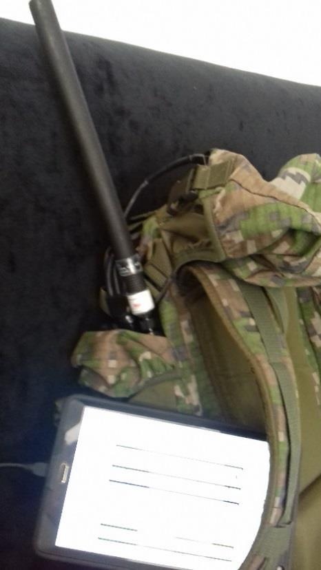
3 Test 1: Open Field / Ground Wave Area of testing: Lat , Long Date: October 25 th, 2016 Weather conditions: Cloudy Photograph of testing area Application Note Page 3
 46.55 21.8 19.6 656 ft (200 m) Antenna 2 37.8 19.6 20.3 Antenna 3 41.45 21.9 20.1 Antenna 1 (SWA) 40.92 20.1 16.")
 32.68 14.3 13.4 1,650 ft (500 m) Antenna 2 21.30 10.7 8.12 Antenna 3 25.62 12.6 10.2 Antenna 1 (SWA) 26.10 13.1 11.5 1,968 ft (600 m) Antenna 2 14.3 -- 6.")
4 Radios used in open field test Test 1 Results Distance Antenna Type SNR (db) Uplink Speed Downlink Speed Antenna 1 (SWA) ft (100 m) Antenna Antenna Antenna 1 (SWA) ft (200 m) Antenna Antenna Antenna 1 (SWA) ft (300 m) Antenna Antenna Antenna 1 (SWA) ,312 ft (400 m) Antenna Antenna Antenna 1 (SWA) ,650 ft (500 m) Antenna Antenna Antenna 1 (SWA) ,968 ft (600 m) Antenna Antenna Application Note Page 4
5 Test 1 Result Conclusions The Southwest Antennas Part # was able to significantly extend the effective operating distance of the radio, especially with distances in excess of 985 feet / 300 meters. At 1,968 feet / 600 meters, Part # offers nearly twice the uplink and downlink speed of the other antenna options. Application Note Page 5

6 Test 2: Forest Area of testing: Lat , Long Date: October 25 th, 2016 Weather condition: Sunny Photograph of testing area Application Note Page 6
 Antenna 2 32.6 13.4 13.1 Antenna 3 35.15 21.1 22.2 Antenna 1 (SWA) 23.3 22.2 22.4 656 ft (200 m) Antenna 2 16.5 9.7 13.")
 Antenna 2 11.3 7.6 8.8 Antenna 3 9.75 8.47 8.47 Antenna 1 (SWA) 1.")
7 Radios used in forest test Test 2 Results Distance Antenna Type SNR (db) Uplink Speed Downlink Speed Antenna 1 (SWA) ft (100 m) Antenna Antenna Antenna 1 (SWA) ft (200 m) Antenna Antenna Antenna 1 (SWA) ft (300 m) Antenna Antenna Antenna 1 (SWA) ,312 ft (400 m) Antenna Antenna Antenna 1 (SWA) ,650 ft (500 m) Antenna Antenna Application Note Page 7
8 Test 2 Conclusions Southwest Antennas Part # continues to improve radio performance at all communication distances, offering a significant uplink and downlink speeds beyond 656 feet / 200 meters. Application Note Page 8

9 Test 3: Urban Area of testing: Lat , Long Date: November 23 rd, 2016 Weather condition: Sunny Radio 1 located inside building, 1 st Floor Office where radio 1 was located during testing (center building) Application Note Page 9

")

10 Urban test locations (left) along road Application Note Page 10
11 Radios used during urban testing Test 3 Results Distance Antenna Type SNR (db) Uplink Speed Downlink Speed Antenna 1 (SWA) ft (100 m) Antenna Antenna Antenna 1 (SWA) ft (200 m) Antenna Antenna Antenna 1 (SWA) ft (250 m) Antenna Antenna Antenna 1 (SWA) ft (300 m) Antenna Antenna Antenna 1 (SWA) ,148 ft (350 m) Antenna Antenna Test 3 Conclusion During the urban testing, Southwest Antennas Part # was able to offer strong uplink and downlink speeds even at the edge of test area, located 1,148 feet / 350 meters from the base radio. Conclusion As testing demonstrates, upgrading to a high-performance antenna is one way to achieve better radio performance in challenging RF environments, and is an easy way to extend the lifespan of radio equipment. For help selecting the proper antennas for your system, please contact Southwest Antennas at sales@southwestantennas.com or call (858) Application Note Page 11
The Reverse Polarity TNC(m) RF connector can be easily secured or removed from equipment in the field by a single gloved hand, no tools required.
 RF connector can be easily secured or removed from equipment in the field by a single gloved hand, no tools required.") Overview Southwest Antennas is a half wave dipole omni antenna with a frequency range of 1.35 to 1.40 GHz and 2.15 dbi of peak gain. This product features an integrated RF bandpass filter to help eliminate
Overview Southwest Antennas is a half wave dipole omni antenna with a frequency range of 1.35 to 1.40 GHz and 2.15 dbi of peak gain. This product features an integrated RF bandpass filter to help eliminate
HyperLink Wireless High Density 2.4/5 GHz Four Element Dual Polarized Flat Panel Antenna Model: HG HDP-4NF
 HyperLink Wireless High Density 2.4/5 GHz Four Element Dual Polarized Flat Panel Antenna Model: HG2458-13HDP-4NF Features Four independent antennas, two vertical and two horizontal Narrow beamwidth for
Advanced Test Equipment Rentals ATEC (2832)
") Established 1981 Advanced Test Equipment Rentals www.atecorp.com 800-404-ATEC (2832) LOG PERIODIC DIPOLES 20 MHz - 18 GHz TRANSMIT - RECEIVE SPECIFICATIONS ELECTRICAL Impedance: 50 ohms INDIVIDUALLY CALIBRATED
Established 1981 Advanced Test Equipment Rentals www.atecorp.com 800-404-ATEC (2832) LOG PERIODIC DIPOLES 20 MHz - 18 GHz TRANSMIT - RECEIVE SPECIFICATIONS ELECTRICAL Impedance: 50 ohms INDIVIDUALLY CALIBRATED
Solution: NF=6 db, B=2.1 GHz, SNR min =7dB T=290 k, P in,1db = 10.5 dbm
 Consider a receiver with a noise figure of 6 db and a bandwidth of 2.1 GHz operating at room temperature. The input 1-dB compression point is 10.5 dbm and the detector at receiver output requires a minimum
HyperLink Wireless 2.4/ 5 GHz Dual Band / Dual Polarized Omni Antenna Model: HG DPU
 HyperLink Wireless 2.4/ 5 GHz Dual Band / Dual Polarized Omni Antenna Model: HG2458-11DPU Applications 2.4/5 GHz IEEE 802.11a/b/g applications Supports 1x2, 2x2 and 4x4 MIMO AP/Routers WiMax, WISP and
SB-400 HF Antennas SB-400
 SB-400 HF Antennas SB-400 The SB-400 Series of antennas are man-portable and rapid-deployable for HF communications. The HF ANTENNA communication mode is for paths from 10 to 400 km. This communication
Using the epmp Link Budget Tool
 Using the epmp Link Budget Tool The epmp Series Link Budget Tool can offer a help to determine the expected performances in terms of distances of a epmp Series system operating in line-of-sight (LOS) propagation
INSTALLATION and OPERATION INSTRUCTIONS. FOR FiberLink BI-DIRECTIONAL AMPLIFIER WITH DIVERSITY MW-FBDA-800AB-50W-DIV
 INSTALLATION and OPERATION INSTRUCTIONS FOR FiberLink BI-DIRECTIONAL AMPLIFIER WITH DIVERSITY MW-FBDA-800AB-50W-DIV Page 1 of 15 TABLE OF CONTENTS PARA No. PARAGRAPH PAGE No. 1. OVERVIEW 3 2. COMPONENT
Unit 3 - Wireless Propagation and Cellular Concepts
 X Courses» Introduction to Wireless and Cellular Communications Unit 3 - Wireless Propagation and Cellular Concepts Course outline How to access the portal Assignment 2. Overview of Cellular Evolution
Colubris Networks. Antenna Guide
 Colubris Networks Antenna Guide Creation Date: February 10, 2006 Revision: 1.0 Table of Contents 1. INTRODUCTION... 3 2. ANTENNA TYPES... 3 2.1. OMNI-DIRECTIONAL ANTENNA... 3 2.2. DIRECTIONAL ANTENNA...
Module contents. Antenna systems. RF propagation. RF prop. 1
 Module contents Antenna systems RF propagation RF prop. 1 Basic antenna operation Dipole Antennas are specific to Frequency based on dimensions of elements 1/4 λ Dipole (Wire 1/4 of a Wavelength) creates
Type 2701 and 2702 Series GRANGER Horizontally Polarized, Log-Periodic HF Antennas
 Type 2701 and 2702 Series GRANGER Horizontally Polarized, Log-Periodic HF Antennas 2-30 MHz Frequency Range Up to kw Average, kw Peak Power Rating Horizontal Polarization 2.0:1 Maximum VSWR Short-to-Medium-Range
FAST MAST ANTENNA SYSTEM
 FAST MAST ANTENNA SYSTEM FAST DEPLOYMENT RECEIVER HITCH 25 ANTENNA TOWER DEPLOY YOUR ANTENNA SYSTEM IN LESS THAN 5 MINUTES THE EXTENDS FROM 7.5 FT UP TO 25 FT OR ANY POINT INBETWEEN. CONSTRUCTED FROM HEAVY
Chapter 6 Antenna Basics. Dipoles, Ground-planes, and Wires Directional Antennas Feed Lines
 Chapter 6 Antenna Basics Dipoles, Ground-planes, and Wires Directional Antennas Feed Lines Some General Rules Bigger is better. (Most of the time) Higher is better. (Most of the time) Lower SWR is better.
Communications Amplifiers: Can They Really Take You Farther and Help You Be Heard Better?
 Communications Amplifiers: Can They Really Take You Farther and Help You Be Heard Better? By: Chris Heavens, Vice President/General Manager, AR Modular RF As a designer and manufacturer of RF amplifiers
INSTRUCTION SHEET WIDEBAND POWER SENSOR MODEL Copyright 2008 by Bird Electronic Corporation Instruction Book P/N Rev.
 INSTRUCTION SHEET WIDEBAND POWER SENSOR MODEL 5012 Copyright 2008 by Bird Electronic Corporation Instruction Book P/N 920-5012 Rev. C Description The Bird 5012 Wideband Power Sensor (WPS) is a Thruline
Huawei Outdoor Wireless Backhaul Solution
 Huawei Outdoor Wireless Backhaul Solution Outdoor Wireless Backhaul Usage Scenarios Wireless video surveillance backhaul Wireless data link Wireless link backup Camera WDS LSW Wireless link backup Long-distance
i-repeater Control and monitor all your repeaters through the cloud
 i-repeater Control and monitor all your repeaters through the cloud GSM, H+, 4G 800/900/1800/2100/2600Mhz Cloud control and monitoring Touch screen interface Diagrams SMA ports for internal antennas X4
RVRUSA - DATA DE REFERENCIA PARA INGENIEROS
 Useful formulae Electrical formulae Electrical power in KW: DC power [KW]: YROW DPSHUH YROW DPSHUH AC power (single phase) [KW]: AC power (three-phase) [KW]: where: cos( j ) YROW DPSHUH 73. cos( j) Volt:
ID SERIES OUTDOOR INDUSTRIAL DIPOLE ANTENNA
 ID SERIES OUTDOOR INDUSTRIAL DIPOLE ANTENNA Phone: (8) 736-6677 / Int: +1 541-471-6256 Email: info@linxtechnologies.com / Address: 159 Ort Lane, Merlin, OR 97532 ID SERIES OUTDOOR INDUSTRIAL DIPOLE ANTENNA
SPECIAL SPECIFICATION 6574 Low Power Wireless Modem
 2004 Specifications CSJ 1068-04-126, etc. SPECIAL SPECIFICATION 6574 Low Power Wireless Modem 1. Description. This work shall consist of furnishing and supplying a Low Power Wireless Modem at the locations
LMS4000 & NCL MHz Radio Propagation
 LMS4000 & NCL1900 900-MHz Radio Propagation This application note is an update to the previous LMS3000/LMS3100 900 MHz Radio Propagation note. It provides general guidelines to estimate CCU3000 & NCL1900
Chapter 5.0 Antennas Section 5.1 Theory & Principles
 Chapter 5.0 Antennas Section 5.1 Theory & Principles G3C11 (B) p.135 Which of the following antenna types will be most effective for skip communications on 40-meters during the day? A. A vertical antenna
Swept Return Loss & VSWR Antenna Measurements using the Eagle Technologies RF Bridge
 Swept Return Loss & VSWR Antenna Measurements using the Eagle Technologies RF Bridge April, 2015 Page 1 of 7 Introduction Return loss and VSWR are a measure of the magnitude of a transmitted RF Signal
Specification for Radiated susceptibility Test
 1 of 11 General Information on Radiated susceptibility test Supported frequency Range : 20MHz to 6GHz Supported Field strength : 30V/m at 3 meter distance 100V/m at 1 meter distance 2 of 11 Signal generator
Application Note: Swept Return Loss & VSWR Antenna Measurements using the Eagle Technologies RF Bridge
 : Swept Return Loss & VSWR Antenna Measurements using the Eagle Technologies RF Bridge FCT-1008A Introduction Return loss and VSWR are a measure of the magnitude of a transmitted RF Signal in relation
High Speed Data Downlink for NSF Space Weather CubeSats
 High Speed Data Downlink for NSF Space Weather CubeSats National Science Foundation Meeting Monday August 31, 2009 Charles Swenson Satellite Data Flow Onboard Instruments R collected Spacecraft Memory
RFID Antenna Family. RFID antennas for fixed readers. Comprehensive RFID antenna portfolio for diverse application needs
 SPECIFICATION SHEET RFID Antenna Family RFID antennas for fixed readers Comprehensive RFID antenna portfolio for diverse application needs Motorola s family of Radio Frequency Identification (RFID) Antennas
Chapter 15: Radio-Wave Propagation
 Chapter 15: Radio-Wave Propagation MULTIPLE CHOICE 1. Radio waves were first predicted mathematically by: a. Armstrong c. Maxwell b. Hertz d. Marconi 2. Radio waves were first demonstrated experimentally
Wireless Antenna Installation Guide
 Wireless Antenna Installation Guide 10 Tips for Making Your Wireless Installation a Success Making Wireless Easy Table of Contents 1 How to Choose the Right Antenna.................2 Yagi Antennas........................
HyperLink Wireless Low PIM MHz Omni-Directional Ceiling Antenna Model: HG35805CUPR-NF
 HyperLink Wireless Low PIM 380-6000 MHz Omni-Directional Ceiling Antenna Model: HG35805CUPR-NF Applications Public Safety DAS (Distributed Antenna Systems) 700 MHz and cellular applications TETRA compliant
The Physics of Radio By John White
 The Physics of Radio By John White Radio Bands and Channels The use of wireless devices is heavily regulated throughout the world. Each country has a government department responsible for deciding where
Submission on Proposed Methodology for Engineering Licenses in Managed Spectrum Parks
 Submission on Proposed Methodology and Rules for Engineering Licenses in Managed Spectrum Parks Introduction General This is a submission on the discussion paper entitled proposed methodology and rules
Wireless Antenna Installation Guide
 Wireless Antenna Installation Guide 10 Tips for Making Your Wireless Installation a Success Making Wireless Easy Connecting Your Industrial Devices - Simply and Reliably International Headquarters 707
INSTALLATION AND OPERATING MANUAL
 INSTALLATION AND OPERATING MANUAL FOR RBDA-PCS-1/25W-90-A INDOOR REPEATER TABLE OF CONTENTS PARAGRAPH PAGE NO BDA OVERVIEW 3 BDA BLOCK DIAGRAM DESCRIPTION 3 FCC INFORMATION FOR USER 3 BDA BLOCK DIAGRAM
9. MAXIMUM CONDUCTED OUTPUT POWER SPECTRAL DENSITY
 9. MAXIMUM CONDUCTED OUTPUT POWER SPECTRAL DENSITY 9.1. MEASUREMENT PROCEDURE (1). Connect EUT RF output port to the Spectrum Analyzer through an RF attenuator (2). Set the EUT Work on the top, the middle
Model:OS NM GHz 5.875GHz 12dBi Outdoor Mini Omni-Directional Antenna. Accessories
 5.125GHz 5.875GHz 12dBi Outdoor Mini Omni-Directional Antenna OS-515912-NM is a high quality of the ISM Band 5.125-5.875ghz Omni-directional antenna can be used for IEEE 802.11a, wireless networks can
The CubeSTAR Project. Design of a Prototype Communication System for the CubeSTAR Nano-satellite. Master presentation by Johan Tresvig 24th Aug.
 Design of a Prototype Communication System for the CubeSTAR Nano-satellite Master presentation by Johan Tresvig 24th Aug. 2010 The CubeSTAR Project Student satellite project at the University of Oslo Scientific
DAMs Universal Link Commander
 Application Note #0428 May 2012 Revised: DAMs Universal Link Commander Application Note The Link Commander enables link analysis with or without DAMs measured data. It also enables range and Bit Error
RFID Antenna Family. RFID antennas for fixed readers. Comprehensive RFID antenna portfolio for diverse application needs
 SPECIFICATION SHEET RFID Antenna Family RFID antennas for fixed readers Comprehensive RFID antenna portfolio for diverse application needs Motorola s family of Radio Frequency Identification (RFID) Antennas
The LoRa Protocol. Overview. Interference Immunity. Technical Brief AN205 Rev A0
 Technical Brief AN205 Rev A0 The LoRa Protocol By John Sonnenberg Raveon Technologies Corp Overview The LoRa (short for Long Range) modulation scheme is a modulation technique combined with a data encoding
Application Note AN-001: Range Extension using NuWaves NuPower Xtender TM Bidirectional Power Amplifiers
 Application Note AN-001: Extension using NuWaves NuPower Xtender TM Bidirectional Power Amplifiers Introduction This application note covers the basics of RF propagation, the effects of fading, multipath,
"High Frequency Ceramic Solutions"
 2.45 GHz Antenna ( Orientation P/N 2450AT45A100 Detail Specification: 07/10/09 Page 1 of 9 General Specifications Part Number 2450AT45A100 Input Power 3W max. Frequency Range 2400-2500 Mhz Impedance 50
Multi-Band Quasi-Omni Antenna
 DATA SHEET Two foot (0.6 m), multi-band, four port quasi-omni antenna with 360 of coverage, covering 698-896 MHz and 1710-2360 MHz frequencies Two wide high band ports covering 1710-2360 MHz and two wide
LRU User Manual March 2002
 User Manual March 2002 To contact SERCEL Nantes, France Commercial; Customer Support; Manufacturing & Repair. B.P. 439, 16 rue de Bel Air 44474 Carquefou Cedex Tel: +33 2 40 30 11 81, Fax: +33 2 40 30
Quick Site Testing with the 8800SX
 Quick Site Testing with the 8800SX Site Testing with the 8800SX Basic Tests 5 site testing involves several tests to verify site operation. NOTE: This is not intended to be a complete commissioning procedure.
ANT-915-CP-0.5 rev.44b Data Sheet Compact Circular Polarized Antenna for RFID
 Applied Wireless Identifications Group, Inc. 18300 Sutter Blvd., Morgan Hill, CA 95037 Tel: 408-825-1100 Fax: 408-782-7402 ANT-915-CP-0.5 rev.44b Data Sheet Compact Circular Polarized Antenna for RFID
Technical Bulletin. DIFFERENT OPERATING MODES, SPECTRAL BEHAVIOUR & DATA THROUGHPUT Prepared by: Jack Van der Star, P.Eng.
 DIFFERENT OPERATING MODES, SPECTRAL BEHAVIOUR & DATA THROUGHPUT Prepared by: Jack Van der Star, P.Eng. This technical bulletin provides observations of spectrum and data throughput behavior under different
Panel Antenna Solutions. Low Profile, Low PIM, Directional Antennas
 Panel Antenna Solutions Low Profile, Low PIM, Directional Antennas About RFI RFI is a global technology solutions company, specialising in wireless coverage. RFI has one of the largest, most innovative
SPECIFICATION : MA700.A.ABC.001
 SPECIFICATION Part No. : MA7.A.ABC.1 Product Name : Pantheon Antenna 3in1 MA.7 Screw-Mount (Permanent Mount) GPS/GLONASS/GALILEO / LTE Cellular / 2.4GHz / GHz Combination Antenna Features : Highest Efficiency/Peak
RECOMMENDATION ITU-R F Radio-frequency channel arrangements for fixed wireless systems operating in the 13 GHz ( GHz) frequency band
 frequency band") Rec. ITU-R F.497-7 1 RECOMMENDATION ITU-R F.497-7 Radio-frequency channel arrangements for fixed wireless systems operating in the 13 GHz (12.75-13.25 GHz) frequency band (Question ITU-R 136/9) (1974-1978-1982-1990-1992-1995-1999-2007)
Rec. ITU-R F.497-7 1 RECOMMENDATION ITU-R F.497-7 Radio-frequency channel arrangements for fixed wireless systems operating in the 13 GHz (12.75-13.25 GHz) frequency band (Question ITU-R 136/9) (1974-1978-1982-1990-1992-1995-1999-2007)
RECOMMENDATION ITU-R SA.1624 *
 Rec. ITU-R SA.1624 1 RECOMMENDATION ITU-R SA.1624 * Sharing between the Earth exploration-satellite (passive) and airborne altimeters in the aeronautical radionavigation service in the band 4 200-4 400
SPECIFICATION PATENT PENDING MHz, MHz. Covers worldwide 4G/3G/2G Bands. Isotropic Radiation Pattern
 SPECIFICATION PATENT PENDING Part No: Product Name: FXUB68.07.0180C Minima Embedded Flexible 4G LTE Wide Band Antenna 700-960MHz, 1700-2700MHz Features: Flexible Wideband Antenna Covers worldwide 4G/3G/2G
RF exposure impact on 5G rollout A technical overview
 RF exposure impact on 5G rollout A technical overview ITU Workshop on 5G, EMF & Health Warsaw, Poland, 5 December 2017 Presentation: Kamil BECHTA, Nokia Mobile Networks 5G RAN Editor: Christophe GRANGEAT,
IT-24 RigExpert. 2.4 GHz ISM Band Universal Tester. User s manual
 IT-24 RigExpert 2.4 GHz ISM Band Universal Tester User s manual Table of contents 1. Description 2. Specifications 3. Using the tester 3.1. Before you start 3.2. Turning the tester on and off 3.3. Main
LOG PERIODIC ANTENNA MODEL LPA MHz - 1 GHz
 INSTRUCTION MANUAL LOG PERIODIC ANTENNA 200 MHz - 1 GHz INSTRUCTION MANUAL THIS INSTRUCTION MANUAL AND ITS ASSOCIATED INFORMATION IS PROPRIETARY. UNAUTHORIZED REPRODUCTION IS FORBIDDEN. 1993 ELECTRO-METRICS
Panel Antenna Solutions
 RFI Panel Antenna Solutions Panel Antenna Solutions Low Profile, Low PIM, Directional Antennas About RFI RFI Panel Antenna Solutions RFI is a global technology solutions company, specialising in wireless
RoamAbout Outdoor Antenna Site Preparation Guide
 9033153 RoamAbout 802.11 Outdoor Antenna Site Preparation Guide Notice Notice Cabletron Systems reserves the right to make changes in specifications and other information contained in this document without
[Uplink_High] 150 ~ 30
![[Uplink_High] 150 ~ 30](/thumbs/93/117947833.jpg "[Uplink_High] 150 ~ 30") Report No.: HCT-R-1611-F007-2 Model: GST-IC-ELITE-1943 Page 97 of 125 9 ~ 150 [Uplink_High] 150 ~ 30 30 ~ 1 1 ~ 1.845 97 / 125 Report No.: HCT-R-1611-F007-2 Model: GST-IC-ELITE-1943 Page 98 of 125 1.845
Report No.: HCT-R-1611-F007-2 Model: GST-IC-ELITE-1943 Page 97 of 125 9 ~ 150 [Uplink_High] 150 ~ 30 30 ~ 1 1 ~ 1.845 97 / 125 Report No.: HCT-R-1611-F007-2 Model: GST-IC-ELITE-1943 Page 98 of 125 1.845
Ultra Wideband Six Beam Antenna
 DATA SHEET Ultra wideband coverage 1695-2690 MHz, including AWS & AWS-3, DCS 1800, PCS, UMTS 2100, WCS and BRS/2.6 GHz bands 3 ft (0.7 m) tall, single panel design supporting six beams without mount changes
Using Variable Coding and Modulation to Increase Remote Sensing Downlink Capacity
 Using Variable Coding and Modulation to Increase Remote Sensing Downlink Capacity Item Type text; Proceedings Authors Sinyard, David Publisher International Foundation for Telemetering Journal International
Title: Test on 5.8 GHz Band Outdoor WiFi (802.11b/g) Wireless Base Station
 Wireless Base Station") Page 20 of 51 Pages 7.5. Conducted spurious emission 7.5.1. Requirements: Clause 15.247(d). In any 100 khz bandwidth outside the frequency band in which the spread spectrum or digitally modulated intentional
Page 20 of 51 Pages 7.5. Conducted spurious emission 7.5.1. Requirements: Clause 15.247(d). In any 100 khz bandwidth outside the frequency band in which the spread spectrum or digitally modulated intentional
Test specification: Section (e)(1), Radiated emissions below 40 GHz Test procedure: ANSI C63.4, Sections 8.3.2, 13.2, 13.4 Test mode: Compliance
(1), Radiated emissions below 40 GHz Test procedure: ANSI C63.4, Sections 8.3.2, 13.2, 13.4 Test mode: Compliance") Test specification: Section 15.253(e)(1), Radiated emissions below 40 GHz Test procedure: ANSI C63.4, Sections 8.3.2, 13.2, 13.4 Plot 7.2.7 Radiated emission measurements at frequency 7280 MHz Low channel
Test specification: Section 15.253(e)(1), Radiated emissions below 40 GHz Test procedure: ANSI C63.4, Sections 8.3.2, 13.2, 13.4 Plot 7.2.7 Radiated emission measurements at frequency 7280 MHz Low channel
RADOME OMNI ANTENNA GHz, 6 dbi, FOAM FILLED
 RADOME OMNI 5.15-5.975 GHz, 6 dbi, FOAM FILLED PAGE 1/8 ISSUE 1525 SERIES RADOME OMNI 5.15-5.975 GHz, 6 dbi, FOAM FILLED PAGE 2/8 ISSUE 1525 SERIES ELECTRICAL CHARACTERISTICS Frequency:..... 5150-5975
Build a Wholesome WLAN Infrastructure with ZyXEL Selected Accessories
 Build a Wholesome WLAN Infrastructure with ZyXEL Selected Accessories Compatible with ZyXEL WLAN devices to get optimal signal quality Matching colors and exterior looks Multiple options to meet your current
Calculated Radio Frequency Emissions Report. Cotuit Relo MA 414 Main Street, Cotuit, MA 02635
 C Squared Systems, LLC 65 Dartmouth Drive Auburn, NH 03032 (603) 644-2800 support@csquaredsystems.com Calculated Radio Frequency Emissions Report Cotuit Relo MA 414 Main Street, Cotuit, MA 02635 July 14,
FCC Test Report. Received Date : Dec. 18, Tested Date : Jan. 08 ~ Jan. 23, 2014
 FCC Test Report FCC ID Equipment Model No. Brand Name Applicant Address Standard : MXF-WLTCS106 : WiMAX Gateway : WLTCS-106 : Gemtek Received Date : Dec. 18, 2013 : Gemtek Technology Co., Ltd. : No. 15-1
Datasheet. 5 GHz Carrier Backhaul Radio. Model: AF-5X. Up to 500+ Mbps Real Throughput, Up to 200+ km Range. Full-Band Certification including DFS
 5 GHz Carrier Backhaul Radio Model: AF-5X Up to 500+ Mbps Real Throughput, Up to 200+ km Range Full-Band Certification including DFS Ubiquiti s INVICTUS Custom Silicon Overview Ubiquiti Networks continues
SAS-543 Biconical Antenna Operation Manual
 SAS-543 Biconical Antenna Operation Manual 1 TABLE OF CONTENTS INTRODUCTION Introduction...3 Intended Purposes...4 Optional Equipment...5 OPERATING INSTRUCTIONS Assembly Instructions...6 Mounting Instructions...6
APPENDIX A TEST PLOTS. (Model: 15Z970)
") APPENDIX A APPENDIX A TEST PLOTS (Model: 15Z970) APPENDIX A-Page 1 of 36 TABLE OF CONTENTS A.1 6dB BANDWIDTH MEASUREMENT... 2 A.1.1 6dB Bandwidth Result... 2 A.1.2 Measurement Plots... 3 A.2 MAXIMUM PEAK
APPENDIX A APPENDIX A TEST PLOTS (Model: 15Z970) APPENDIX A-Page 1 of 36 TABLE OF CONTENTS A.1 6dB BANDWIDTH MEASUREMENT... 2 A.1.1 6dB Bandwidth Result... 2 A.1.2 Measurement Plots... 3 A.2 MAXIMUM PEAK
Small Cell 65 Degree Panel Antenna
 DATA SHEET Small Cell Sector antenna optimized over the PCS (1850-1995 MHz) and BRS (2496 to 2690 MHz) bands Cross-Pol design for 2x2 MIMO Excellent upper sidelobe suppression Designed for superior Front
Wideband Quasi-Omni Antenna
 DATA SHEET Two foot (0.5 m), two port, quasi-omni antenna with uniform horizontal beamwidths covering the extended band from 1710-2690 MHz 360 of coverage area across all bands of operation in a single
Antenna Basics. Antennas. A guide to effective antenna use
 A guide to effective antenna use Antennas Antennas transmit radio signals by converting radio frequency electrical currents into electromagnetic waves. Antennas receive the signals by converting the electromagnetic
RF Test Accessories. Antenna Coupler. TC-93010C fitted with F930102A TC-93013A. Frequency Range : 820 ~ 960 MHz. Frequency Range : 0.
 RF Test Accessories Antenna Coupler TC-93010C Tubular Type Antenna Coupler Frequency Range : 0.8 ~ 2GHz RF Connector : SMA(f) Weight : 60g Patent Pending # 2001-24403 Hole Size : 11mm TC-93010C fitted
4/29/2012. General Class Element 3 Course Presentation. Ant Antennas as. Subelement G9. 4 Exam Questions, 4 Groups
 General Class Element 3 Course Presentation ti ELEMENT 3 SUB ELEMENTS General Licensing Class Subelement G9 Antennas and Feedlines 4 Exam Questions, 4 Groups G1 Commission s Rules G2 Operating Procedures
Mobile RF Linear Amplifier
 Features High Reliability Design +13.8VDC Operation All Mode (AM, FM, SSB) 10-Meter Amateur Band Coverage Temperature Tracking Class-AB Bias High Output Power / Low Harmonic Content Quad MRF454 Configuration
iant101 Zone 1 Omni Directional Antenna
 iant101 Zone 1 Omni Directional Antenna External Antenna offering increased flexibility for positioning and greatly enhanced RF Propagation. ATEX Ex t IIIC T85 C Db IECEx Ex t IIIC T85 C Db -40 C to 60
CHAPTER 5 PRINTED FLARED DIPOLE ANTENNA
 CHAPTER 5 PRINTED FLARED DIPOLE ANTENNA 5.1 INTRODUCTION This chapter deals with the design of L-band printed dipole antenna (operating frequency of 1060 MHz). A study is carried out to obtain 40 % impedance
Yagi beam antennas CHAPTER 10 COMPOSITION OF A BEAM ANTENNA _
 CHAPTER 10 Yagi beam antennas The Yagi beam antenna (more correctly, the Yagi Uda antenna, after both of the designers of Tohoku University in Japan 1926) is unidirectional. It can be vertically polarized
360 inches (915 cm) 240 inches (610 cm) 120 inches (305 cm) 240 inches is the recommended pole length, 360 inches is the recommended free space area
 240 inches (610 cm) 120 inches (305 cm) 240 inches is the recommended pole length, 360 inches is the recommended free space area") FML C/P FM Antenna Right hand C/P Polarization Low wind load area Up to 1 kw Rating per bay Omni-directional Up to 8 kw input per array with power divider options The FML series of antennas are narrow
FML C/P FM Antenna Right hand C/P Polarization Low wind load area Up to 1 kw Rating per bay Omni-directional Up to 8 kw input per array with power divider options The FML series of antennas are narrow
Novel Broadband and Multi-band Antennas for Satellite and Wireless Applications
 Novel Broadband and Multi-band Antennas for Satellite and Wireless Applications The objective of our research is to develop novel antenna structures for broadband and/or multi-band satellite and wireless
Low Wideband Quasi-Omni Antenna
 DATA SHEET Two foot (0.7 m), singleband, two port quasi-omni antenna with 360 of coverage, covering 694-960 MHz frequencies Two wide low band ports covering 694-960 MHz in a low weight and low profile
RAPTORXR. Broadband TV White Space (TVWS) Backhaul Digital Radio System
 Backhaul Digital Radio System") RAPTORXR Broadband TV White Space (TVWS) Backhaul Digital Radio System TECHNICAL OVERVIEW AND DEPLOYMENT GUIDE CONTACT: BBROWN@METRICSYSTEMS.COM Broadband White Space Mesh Infrastructure LONG REACH - FAST
RAPTORXR Broadband TV White Space (TVWS) Backhaul Digital Radio System TECHNICAL OVERVIEW AND DEPLOYMENT GUIDE CONTACT: BBROWN@METRICSYSTEMS.COM Broadband White Space Mesh Infrastructure LONG REACH - FAST
Technology and Market Trends in Millimeter Waves
 Atmospheric Attenuation vs. Altitude for US Std Conditions 100000 10000 Attenuation (db/km) 1000 100 10 1 0.1 0.01 0.001 0 ft 5000 ft 10000 ft 15000 ft 20000 ft 25000 ft 30000 ft 35000 ft 40000 ft 45000
SPECIFICATION. MIMO Dual Band 2.4/5.0GHz. ISM Bands/ZigBee/WLAN/Bluetooth. IEEE n/IEEE ac. High Isolation between Antenna Elements
 SPECIFICATION Part No. : MA510.C.CG.005 Product Name : Heavy Duty Screw Mount Antenna MIMO Dual Band 2.4/5.0GHz Features : 2.4GHz/5.0GHz suitable for ISM Bands/ZigBee/WLAN/Bluetooth IEEE.802.11n/IEEE.802.11ac
Project PTP 820S 2+0 Co-Polar ACCP
 Project PTP 80S +0 Co-Polar ACCP 017-07-17 LINKPlanner PTP Installation Report 17 July 017 David Hensley Organization: Cambium Networks Phone: 6309186050 Email: david.hensley@cambiumnetworks.com center
Datasheet. Licensed Backhaul Radio. Model: AF-4X. Up to 687 Mbps Real Throughput, Up to 200+ km Range
 Licensed Backhaul Radio Model: AF-4X Up to 687 Mbps Real Throughput, Up to 200+ km Range Optimal Use of 4.9 GHz Radio Band for Public Safety Sector Ubiquiti s INVICTUS Custom Silicon Overview Ubiquiti
Antenna. Wilson. Wide-Band Panel Antenna Window, Ceiling, Wall & Outdoor Mounts. Appearance of device and accessories may vary.
 Antenna Window, Ceiling, Wall & Outdoor Mounts WINDOW PART# 304452-50 Ohms PART# 304472-75 Ohms CEILING PART# 304451-50 Ohms PART# 304471-75 Ohms WALL PART# 301135-50 Ohms UPGRADE-PART# 301147-50 Ohms
Ham Radio Activities at Marshall Space Flight Center during the 2017 Total Solar Eclipse: Transmitting Node
 Ham Radio Activities at Marshall Space Flight Center during the 2017 Total Solar Eclipse: Transmitting Node HamSCI Workshop February 23-24, 2018 NJIT, Newark, NJ Jesse McTernan, USRA/MSFC (KN4EZR) Linda
6 Radio and RF. 6.1 Introduction. Wavelength (m) Frequency (Hz) Unit 6: RF and Antennas 1. Radio waves. X-rays. Microwaves. Light
 Frequency (Hz) Unit 6: RF and Antennas 1. Radio waves. X-rays. Microwaves. Light") 6 Radio and RF Ref: http://www.asecuritysite.com/wireless/wireless06 6.1 Introduction The electromagnetic (EM) spectrum contains a wide range of electromagnetic waves, from radio waves up to X-rays (as
6 Radio and RF Ref: http://www.asecuritysite.com/wireless/wireless06 6.1 Introduction The electromagnetic (EM) spectrum contains a wide range of electromagnetic waves, from radio waves up to X-rays (as
August, Antennas 101: A Course in RF Basics
 August, 2012 Antennas 101: A Course in RF Basics Antenna Basics Agenda: In today s training, we will go over a brief summary of the following topics at a basic level: Electromagnetic Waves Frequency and
GSM DCS WCDMA Triple Band Repeater
 CRF-GDW27-F GSM DCS WCDMA Triple Band Repeater Gain 80dB, Output 27dBm Overview: CRF-GDW27-F wireless Pico Repeater is a fast and cost effective solution widely deployed to provide coverage improvement
Technician Licensing Class T9
 Technician Licensing Class T9 Amateur Radio Course Monroe EMS Building Monroe, Utah January 11/18, 2014 January 22, 2014 Testing Session Valid dates: July 1, 2010 June 30, 2014 Amateur Radio Technician
The Vertical Buddi Beam on 20m using no Coils.
 The Vertical Buddi Beam on 20m using no Coils. design by Lou Rummel KE4UYP In this article I am going to describe a totally new way to construct and use a very old design the two element Yagi antenna.
HyperLink Wireless Low PIM DAS 2x2 MIMO Ceiling Antenna Model: HG72706DPCUPR-NF
 HyperLink Wireless Low PIM DAS 2x2 MIMO Ceiling Antenna Model: HG72706DPCUPR-NF Applications DAS (Distributed Antenna Systems) 700 MHz and cellular applications AWS (Advanced wireless services) and PCS
Air Band Multicoupling Products MHz MHz
 Air Band Multicoupling Products 118-137 MHz 225-400 MHz AFL Proposal Page: 1 of 12 Air Band Cavity Filters Key Features Low Insertion Loss Easy to install 19 Rack Mount High isolation TX-TX MTBF > 500,000
Exploiting Link Dynamics in LEO-to-Ground Communications
 SSC09-V-1 Exploiting Link Dynamics in LEO-to-Ground Communications Joseph Palmer Los Alamos National Laboratory MS D440 P.O. Box 1663, Los Alamos, NM 87544; (505) 665-8657 jmp@lanl.gov Michael Caffrey
COPYRIGHT 2010 MESHDYNAMICS, INC. ALL RIGHTS RESERVED. DISCLOSURES PROTECTED BY MULTIPLE PATENTS
 COPYRIGHT 2010 MESHDYNAMICS, INC ALL RIGHTS RESERVED DISCLOSURES PROTECTED BY MULTIPLE PATENTS COPYRIGHT 2010 MESHDYNAMICS, INC ALL RIGHTS RESERVED DISCLOSURES PROTECTED BY MULTIPLE PATENTS long-range
Co-Existence of UMTS900 and GSM-R Systems
 Asdfadsfad Omnitele Whitepaper Co-Existence of UMTS900 and GSM-R Systems 30 August 2011 Omnitele Ltd. Tallberginkatu 2A P.O. Box 969, 00101 Helsinki Finland Phone: +358 9 695991 Fax: +358 9 177182 E-mail:
OMNI-DIRECTIONAL WIDEBAND ANTENNA MODEL EM GHz - 18 GHz
 INSTRUCTION MANUAL OMNI-DIRECTIONAL WIDEBAND ANTENNA MODEL EM-6865 2 GHz - 18 GHz INSTRUCTION MANUAL THIS INSTRUCTION MANUAL AND ITS ASSOCIATED INFORMATION IS PRO- PRIETARY. UNAUTHORIZED REPRO- DUCTION