Spectrum Analysis with HP-IB Systems
|
|
|
- Reginald May
- 5 years ago
- Views:
Transcription

1 Spectrum Analysis with HP-IB Systems HEWLETT jm] PACKARD

2 Measuring Wide-Band Noise with the HP 3045A The purpose of this application note is to outline the basic concerns of measuring noise with the 3045A Spectrum Analyzer. The possible sources of error are discussed and a program for the HP 9825A Controller is presented for making noise measurements in bandwidths wider than the 10 khz available in the HP 3571 A. Description of Method The technique and theory for measuring narrow-band noise with a spectrum analyzer are described in HP Application Note As shown in that note, spectrum analyzers read 2.5 db low on random noise measurements because of their logarithmic amplifier and envelope detector. Also, the noise power bandwidth of the filters is defined and shown to be about 12% wider than the 3 db bandwidth. Because the 3 db bandwidth can vary as much as 20%, a subroutine is provided in the following program for measuring the noise power bandwidth for each bandwidth setting. Minimum Noise Maximum Analyzer Noise Power Noise Filter Frequency Bandwidth Frequency Shape Wide-Band Noise Measurement Technique To measure noise in a wider bandwidth than the 10 khz available with the 3045A, it is necessary to take a series of properly spaced readings across the desired frequency band, convert them to power, sum them, convert the results back to db and add the 2.5 db mentioned above. This is easily done in a calculator-controlled spectrum analyzer like the 3045A. It is important at low frequencies to use a narrow enough bandwidth so that the local oscillator feed-through does not raise the noise floor. At higher frequencies, it is desirable for the sake of speed to use a wider bandwidth both because of its faster settling time and because fewer measurements are required to cover the desired frequency band. To assure that all the noise in the desired frequency band is measured, the readings are taken at frequencies spaced by the noise power bandwidth. Finally, 10 readings are taken at each frequency and averaged. This entire process is shown in Figure 1. The noise measurement subroutine in the program takes all these considerations into account and its results consistently agree with a true RMS measurement of band-limited, white noise to within ±0.2 db. Potential Source of Measurement Error The main problem with this measurement technique is that it doesn't actually measure the true RMS value of the signals in the desired frequency band. Thus, if a coherent signal is present in the measurement range, it can be emphasized by as much as the 2.5 db correction factor mentioned above. Also, if the noise is not white (i.e., not frequency flat) but steeply slopes through the noise power bandwidth, the reading will be in error. This is because the reading is an average, not true RMS. This error can be minimized if, as is typically the case, the frequency regions of non-white noise are known (e.g. low frequencies typically have 1/f noise).if narrow bandwidths are used in these regions, the measurement error will be reduced because within the noise power bandwidth, the noise is closer to white. The program presented later can be modified by the user to minimize this error in his problem frequency range. Disagreement with other Kinds of Analyzers Just as spectrum analyzers need a 2.5 db correction factor, other kinds of analyzers which are not true RMS require their own correction factors. For instance, the HP 331A Distortion Analyzer can be used as a wide band voltmeter, but its meter is average responding. This causes the 331 to read 1.05 db lower than a true RMS measurement when measuring white noise. Analyzers can disagree because they are measuring in different bandwidths. For instance, it may be desired to measure the noise in an audio amplifier. In this case, we are interested in the noise only from 20 Hz to 20 khz as this is the maximum range the ear can hear. This is easily done with the 3045A program, but without external filters the 331A will measure the noise out to several megahertz. As there could be significant noise beyond 20 khz, the 331A might read considerably higher than the desired result. One must not depend on the roll-off of the audio amplifier to limit the noise as it often will not. A third possible source of disagreement occurs when the noise measured by the 3045A and another non-rms analyzer is not frequency flat or contains coherent signals (tones). As stated before, the 3045A will not read the same as a true-rms measurement. In addition, the other analyzer will also be in error, but not by the same amount. Therefore, both analyzers can give a wrong answer, but not necessarily the same wrong answer. Finally, the possible lack of accuracy of the comparison analyzer can cause disagreement with the 3045A. This can be minimized by calibrating the analyzer at the normally expected noise level. Actual Measurements Despite all the warnings, it should be pointed out that a 331A calibrated at the noise level read consistently within.18 db of the 3045A on band-limited white noise.
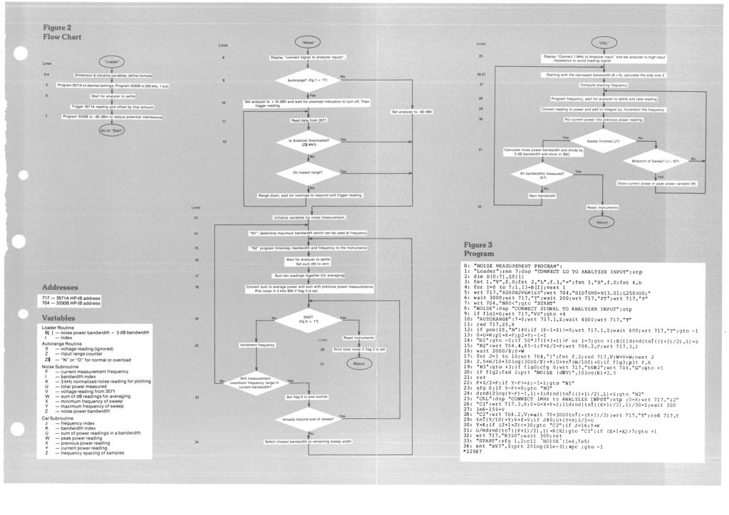
3 Program Description A flowchart for the program is given in figure 2 and the program itself is in figure 3. The program is actually a series of subroutines which can be called by the programmer to execute the desired measurement. The user's program which calls these routines starts on line 33 and is labeled "START". A typical two-line user program is included in the listing. This format makes it easy for the programmer to incorporate these routines in his own program. After the system has warmed up, the program can be run as follows. Lines 1-4 dimension the variables and set up the formats. The user must connect the 3330B synthesizer output to the input of the 3571A analyzer when prompted by the display "CONNECT LO TO ANA LYZER INPUT". This allows the software to calibrate the system to 0 db with a 1 volt input from the 3330B (50 0). This is done in lines 5-7. These lines also program the instruments to the desired test conditions. The program then jumps to line 33, the user's program. Here the user can call the U CAL" or "NOISE" subroutine or a routine he has added to the program. The "CAL" subroutine (lines 25-32) measures the noise power bandwidth of every bandwidth setting of the It does this by tuning the analyzer about a 1 MHz signal. The user must connect this signal from the rear panel when prompted by the message "CONNECT 1 MHz TO ANALYZER INPUT" (line 25). The subroutine measures the noise power bandwidth by a 30 point trapazoidal approximation to a true integral of power between the -60 db points of the filter and divides this integral by the peak power. The results are stored normalized to the 3 db bandwidth in B[0] to B[7] (3 Hz to 10 khz respectively). Since the noise power bandwidth is stable and this routine takes just over one minute to execute, it is recommended that it be done infrequently. (It is perhaps sufficiently accurate for most applications to use the nominal values of B[ ] set up in the Loader routine, line 4. This can be determined by experiment.) No variables need to be passed to the "CAL" routine. The "NOISE" routine (lines 8-24), on the other hand, needs several variables. These are: pi minimum freq. of desired measurement p2 maximum freq. of desired measurement flag 1 set for autoranging input flag 2 set to print total noise flag 3 set to plot noise vs. frequency The example user's program in line 33 measures the noise from 10 khz to 700 khz. Flag 1 is set to autorange the input (lines 10-13) until it is one range overloaded. This is the best range for noise measurements where harmonic distortion is generally not a problem. If flag 1 were not set, the analyzer would be set to its -60 dbv range by line 9, which would speed the test by avoiding the autorange routine. Flag 2 is set to print the total noise on the calculator printer (line 20), otherwise there would be no output at all. Flag 3 could be set to plot the noise in dbv normalized to a 3 khz bandwidth on a HP 9862 Plotter (line 18). A "Scale" statement is needed in the user's program if the plotter is to be used. This and any axes drawing or labeling can be added by the programmer to suit his own particular requirement. The user program example (lines 33-34) is a simple program to measure band-limited noise with the 3045A and then ask the user to input the mv reading from a true RMS voltmeter. Both answers are printed in dbv for ease of comparison and then the controller starts another measurement. The number of possible user programs is large and the programmer is encouraged to experiment.
4
5 HEWLETT [hpj PACKARD For more information, call your local HP Sales Office or East (201) Midwest (312) South (404) West (213) Or write: Hewlett-Packard, 1501 f Mill Road, Palo Alto, California In Europe: P.O. Box 85, CH-1217 Meyrin 2, Geneva, Switzerland. In Japan: YHP, , Yoyogi, Shibuya-Ku, Tokyo, 151. Printed in U.S.A. October,
Brief review of the concept and practice of third octave spectrum analysis
 Low frequency analyzers based on digital signal processing - especially the Fast Fourier Transform algorithm - are rapidly replacing older analog spectrum analyzers for a variety of measurement tasks.
HP 8901B Modulation Analyzer. HP 11722A Sensor Module. 150 khz MHz. 100 khz MHz. Technical Specifications. Four Instruments In One
 HP 8901B Modulation Analyzer 150 khz - 1300 MHz HP 11722A Sensor Module 100 khz - 2600 MHz Technical Specifications Four Instruments In One RF Power: ±0.02 db instrumentation accuracy RF Frequency: 10
Glossary of VCO terms
 Glossary of VCO terms VOLTAGE CONTROLLED OSCILLATOR (VCO): This is an oscillator designed so the output frequency can be changed by applying a voltage to its control port or tuning port. FREQUENCY TUNING
Model 4402B. Ultra-Pure Sinewave Oscillator 1Hz to 110kHz Typical Distortion of % Serial No. Operating Manual
 Model 4402B Ultra-Pure Sinewave Oscillator 1Hz to 110kHz Typical Distortion of 0.0005% Serial No. Operating Manual 15 Jonathan Drive, Unit 4, Brockton, MA 02301 U.S.A. Tel: (508) 580-1660; Fax: (508) 583-8989
HP 8901B Modulation Analyzer. HP 11722A Sensor Module. 150 khz MHz. 100 khz MHz. Technical Specifications. Four Instruments In One
 HP 8901B Modulation Analyzer 150 khz - 1300 MHz HP 11722A Sensor Module 100 khz - 2600 MHz Technical Specifications Four Instruments In One RF Power: ±0.02 db instrumentation accuracy RF Frequency: 10
PEARSON ELECTRONICS POWERLINE RIPPLE DETECTOR MODEL PRD-120 OPERATING MANUAL
 PEARSON ELECTRONICS POWERLINE RIPPLE DETECTOR MODEL PRD-120 OPERATING MANUAL Description. The Pearson PRD-120 facilitates the measurement of power line ac ripple using a frequency selective voltmeter,
3439A 3440A 3441A DIGITAL VOLTMETER. HEWLETT ftp] PACKARD 3444A 3445A 3446A TECHNICAL DATA 6 APRIL TO RESISTANCE
![3439A 3440A 3441A DIGITAL VOLTMETER. HEWLETT ftp] PACKARD 3444A 3445A 3446A TECHNICAL DATA 6 APRIL TO RESISTANCE](/thumbs/96/126991047.jpg "3439A 3440A 3441A DIGITAL VOLTMETER. HEWLETT ftp] PACKARD 3444A 3445A 3446A TECHNICAL DATA 6 APRIL TO RESISTANCE") HEWLETT ftp] PACKARD m DIGITAL VOLTMETER 3439A 3440A 3441A 3444A 3445A 3446A TECHNICAL DATA 6 APRIL TO RESISTANCE GENERAL The 3439A and 3440A are general purpose 4-digit Digital Voltmeters able to measure
HEWLETT ftp] PACKARD m DIGITAL VOLTMETER 3439A 3440A 3441A 3444A 3445A 3446A TECHNICAL DATA 6 APRIL TO RESISTANCE GENERAL The 3439A and 3440A are general purpose 4-digit Digital Voltmeters able to measure
TECHNICAL MANUAL CALIBRATION PROCEDURE FOR SYNTHESIZED SIGNAL GENERATOR 7200() (GIGA-TRONICS)
 (GIGA-TRONICS)") T.O. 33K3-4-3051-1 TECHNICAL MANUAL CALIBRATION PROCEDURE FOR SYNTHESIZED SIGNAL GENERATOR 7200() (GIGA-TRONICS) This publication replaces TO. 33K3-4-3051-1 dated 30 July 1997 and Change 1 30 December
T.O. 33K3-4-3051-1 TECHNICAL MANUAL CALIBRATION PROCEDURE FOR SYNTHESIZED SIGNAL GENERATOR 7200() (GIGA-TRONICS) This publication replaces TO. 33K3-4-3051-1 dated 30 July 1997 and Change 1 30 December
EXHIBIT 3 : FCC (c) (TEST DATA) AND FCC (MEASUREMENT PROCEDURES) INTRODUCTION TO TRANSMITTER MEASUREMENTS, Part 2.
 (TEST DATA) AND FCC (MEASUREMENT PROCEDURES) INTRODUCTION TO TRANSMITTER MEASUREMENTS, Part 2.") EXHIBIT 3 : FCC 2.1033(c) (TEST DATA) AND FCC 2.1041 (MEASUREMENT PROCEDURES) INTRODUCTION TO TRANSMITTER MEASUREMENTS, Part 2.1033(c)(14) Exhibits 4 through 9 on the following pages present the required
EXHIBIT 3 : FCC 2.1033(c) (TEST DATA) AND FCC 2.1041 (MEASUREMENT PROCEDURES) INTRODUCTION TO TRANSMITTER MEASUREMENTS, Part 2.1033(c)(14) Exhibits 4 through 9 on the following pages present the required
100 Hz to 22. HP 8566B Spectrum Analyzer. Discontinued Product Support Information Only. Outstanding Precision and Capability
 Discontinued Product Support Information Only This literature was published years prior to the establishment of Agilent Technologies as a company independent from Hewlett-Packard and describes products
Low voltage high performance mixer FM IF system
 DESCRIPTION The is a low voltage high performance monolithic FM IF system incorporating a mixer/oscillator, two limiting intermediate frequency amplifiers, quadrature detector, logarithmic received signal
MEASURING HUM MODULATION USING MATRIX MODEL HD-500 HUM DEMODULATOR
 MEASURING HUM MODULATION USING MATRIX MODEL HD-500 HUM DEMODULATOR The SCTE defines hum modulation as, The amplitude distortion of a signal caused by the modulation of the signal by components of the power
Data Sheet SC5317 & SC5318A. 6 GHz to 26.5 GHz RF Downconverter SignalCore, Inc. All Rights Reserved
 Data Sheet SC5317 & SC5318A 6 GHz to 26.5 GHz RF Downconverter www.signalcore.com 2018 SignalCore, Inc. All Rights Reserved Definition of Terms 1 Table of Contents 1. Definition of Terms... 2 2. Description...
Measurement in Coax 84
 HEWLETT lpl PACKARD SXA/R application note Measurement in Coax 84 -\B 6T - Slotted Line Accuracy - 2 to 1B GHz For more information, call your local HP Sales Office or East (201) 265-5000 Midwest (312)
Lab Exercise PN: Phase Noise Measurement - 1 -
 Lab Exercise PN: Phase Noise Measurements Phase noise is a critical specification for oscillators used in applications such as Doppler radar and synchronous communications systems. It is tricky to measure
Agilent 8901B Modulation Analyzer (150 khz 1300 MHz) and Agilent 11722A Sensor Module (100 khz 2600 MHz) Four Instruments In One
 and Agilent 11722A Sensor Module (100 khz 2600 MHz) Four Instruments In One") Agilent 8901B Modulation Analyzer (150 khz 1300 MHz) and Agilent 11722A Sensor Module (100 khz 2600 MHz) Four Instruments In One Data Sheet RF Power: ±0.02 db instrumentation accuracy RF Frequency: 10
Agilent 8901B Modulation Analyzer (150 khz 1300 MHz) and Agilent 11722A Sensor Module (100 khz 2600 MHz) Four Instruments In One Data Sheet RF Power: ±0.02 db instrumentation accuracy RF Frequency: 10
 HP 8901A Modulation Analyzer 150 khz to 1300 MHz Product Overview Measurements* Frequency Range: 150 khz to 1300 MHz Resolution: 10 Hz below 1000 MHz, 100 Hz above 1000 MHz Input Level: Automatic Mode:
FIRST WATT B4 USER MANUAL
 FIRST WATT B4 USER MANUAL 6/23/2012 Nelson Pass Introduction The B4 is a stereo active crossover filter system designed for high performance and high flexibility. It is intended for those who feel the
HP Archive. This vintage Hewlett Packard document was preserved and distributed by www. hparchive.com Please visit us on the web!
 HP Archive This vintage Hewlett Packard document was preserved and distributed by www. hparchive.com Please visit us on the web! On-line curator: Glenn Robb This document is for FREE distribution only!
Accurate Phase Noise Measurements Made Cost Effective
 MTTS 2008 MicroApps Accurate Phase Noise Measurements Made Cost Effective author : Jason Breitbarth, PhD. Boulder, Colorado, USA Presentation Outline Phase Noise Intro Additive and Absolute Oscillator
Agilent 8902A Measuring Receiver
 Agilent 8902A Measuring Receiver Technical Specifications Agilent 11722A Sensor Module Agilent 11792A Sensor Module Agilent 11793A Microwave Converter Agilent 11812A Verification Kit The Agilent Technologies
2014 Short Form Test and Measurement Catalog
 2014 Short Form Test and Measurement Catalog Quality Products Since 1949 DC Source/Calibrators Tunable Active Filters Filter Systems Filter Modules Wideband Power Amplifiers Precision Phasemeters Distortion
Calibration Techniques for the Home Lab
 Calibration Techniques for the Home Lab Jacques Audet VE2AZX jacaudet@videotron.ca Web: ve2azx.net September 2018 ve2azx.net 1 Summary - Using a reference multimeter as a calibrator for less accurate instruments.
FFT Spectrum Analyzer
 FFT Spectrum Analyzer SR770 100 khz single-channel FFT spectrum analyzer SR7770 FFT Spectrum Analyzers DC to 100 khz bandwidth 90 db dynamic range Low-distortion source Harmonic, band & sideband analysis
W-band vector network analyzer based on an audio lock-in amplifier * Abstract
 SLAC PUB 7884 July 1998 W-band vector network analyzer based on an audio lock-in amplifier * R. H. Siemann Stanford Linear Accelerator Center, Stanford University, Stanford CA 94309 Abstract The design
OPERATING AND MAINTENANCE MANUAL
 5Hz to 1MHz WIDE RANGE FULLY AUTOMATIC DISTORTION ANALYZER MODEL 6900B SERIAL NO. OPERATING AND MAINTENANCE MANUAL Unit 4, 15 Jonathan Drive, Brockton, MA 02301-5566 Tel: (508) 580-1660; Fax: (508) 583-8989
Model Phase Angle Voltmeter. Features: Description: Typical Applications:
 Model 2250 Phase Angle Voltmeter Features: 700Vpk Reference and Signal Inputs Wide Frequency Response Isolated Reference and Signal Inputs Up to 86 db Harmonic Rejection Ratio Measurement Capabilities
A year and a half after the first introduction of the PXA, Agilent is now introducing the world s highest performance mmw signal analyzer in April
 1 This presentation is intended to be a beginning tutorial on signal analysis. Vector signal analysis includes but is not restricted to spectrum analysis. It is written for those who are unfamiliar with
Swept-tuned spectrum analyzer. Gianfranco Miele, Ph.D
 Swept-tuned spectrum analyzer Gianfranco Miele, Ph.D www.eng.docente.unicas.it/gianfranco_miele g.miele@unicas.it Reference level and logarithmic amplifier The signal displayed on the instrument screen
6.101 Project Proposal April 9, 2014 Kayla Esquivel and Jason Yang. General Outline
 6.101 Project Proposal April 9, 2014 Kayla Esquivel and Jason Yang General Outline We will build a superheterodyne AM Radio Receiver circuit that will have a bandwidth of the entire AM spectrum, and whose
Utilizzo del Time Domain per misure EMI
 Utilizzo del Time Domain per misure EMI Roberto Sacchi Measurement Expert Manager - Europe 7 Giugno 2017 Compliance EMI receiver requirements (CISPR 16-1-1 ) range 9 khz - 18 GHz: A normal +/- 2 db absolute
Restoration Performance Report
 Restoration Performance Report Report Date: July 15, 2015 Manufacturer: Fisher Model: 500-C Receiver Special Notes: Full Gold Level Restoration service completed. Chassis ultrasonically cleaned. All coupling
Modification Details.
 Front end receiver modification for DRM: AKD Target Communications receiver. Model HF3. Summary. The receiver was modified and capable of receiving DRM, but performance was limited by the phase noise from
SC5307A/SC5308A 100 khz to 6 GHz RF Downconverter. Datasheet SignalCore, Inc.
 SC5307A/SC5308A 100 khz to 6 GHz RF Downconverter Datasheet 2017 SignalCore, Inc. support@signalcore.com P RODUCT S PECIFICATIONS Definition of Terms The following terms are used throughout this datasheet
PHASE NOISE MEASUREMENT SYSTEMS
 PHASE NOISE MEASUREMENT SYSTEMS Item Type text; Proceedings Authors Lance, A. L.; Seal, W. D.; Labaar, F. Publisher International Foundation for Telemetering Journal International Telemetering Conference
Twelve voice signals, each band-limited to 3 khz, are frequency -multiplexed using 1 khz guard bands between channels and between the main carrier
 Twelve voice signals, each band-limited to 3 khz, are frequency -multiplexed using 1 khz guard bands between channels and between the main carrier and the first channel. The modulation of the main carrier
LLS - Introduction to Equipment
 Published on Advanced Lab (http://experimentationlab.berkeley.edu) Home > LLS - Introduction to Equipment LLS - Introduction to Equipment All pages in this lab 1. Low Light Signal Measurements [1] 2. Introduction
Real-Time FFT Analyser - Functional Specification
 Real-Time FFT Analyser - Functional Specification Input: Number of input channels 2 Input voltage ranges ±10 mv to ±10 V in a 1-2 - 5 sequence Autorange Pre-acquisition automatic selection of full-scale
ECE 440L. Experiment 1: Signals and Noise (1 week)
") ECE 440L Experiment 1: Signals and Noise (1 week) I. OBJECTIVES Upon completion of this experiment, you should be able to: 1. Use the signal generators and filters in the lab to generate and filter noise
ECE 440L Experiment 1: Signals and Noise (1 week) I. OBJECTIVES Upon completion of this experiment, you should be able to: 1. Use the signal generators and filters in the lab to generate and filter noise
POWER-MEASUREMENT needs can vary greatly among different
 Measuring Power Levels In Modern Communications Systems A choice of video bandwidths and time-gating capabilities can increase the accuracy and effectiveness of power measurements on modern wireless-communications
A Guide to Calibrating Your Spectrum Analyzer
 A Guide to Calibrating Your Application Note Introduction As a technician or engineer who works with electronics, you rely on your spectrum analyzer to verify that the devices you design, manufacture,
HP 8560 E-Series Spectrum Analyzers Technical Specifications
 HP 8560 E-Series Spectrum Analyzers Technical Specifications HP 8560E 30 Hz to 2.9 GHz HP 8561E 30 Hz to 6.5 GHz HP 8562E 30 Hz to 13.2 GHz HP 8563E 30 Hz to 26.5 GHz HP 8564E 30 Hz to 40 GHz HP 8565E
A NEW GENERATION PROGRAMMABLE PHASE/AMPLITUDE MEASUREMENT RECEIVER
 GENERAL A NEW GENERATION PROGRAMMABLE PHASE/AMPLITUDE MEASUREMENT RECEIVER by Charles H. Currie Scientific-Atlanta, Inc. 3845 Pleasantdale Road Atlanta, Georgia 30340 A new generation programmable, phase-amplitude
LIMITATIONS IN MAKING AUDIO BANDWIDTH MEASUREMENTS IN THE PRESENCE OF SIGNIFICANT OUT-OF-BAND NOISE
 LIMITATIONS IN MAKING AUDIO BANDWIDTH MEASUREMENTS IN THE PRESENCE OF SIGNIFICANT OUT-OF-BAND NOISE Bruce E. Hofer AUDIO PRECISION, INC. August 2005 Introduction There once was a time (before the 1980s)
Keysight Technologies Optimizing RF and Microwave Spectrum Analyzer Dynamic Range. Application Note
 Keysight Technologies Optimizing RF and Microwave Spectrum Analyzer Dynamic Range Application Note 02 Keysight Optimizing RF and Microwave Spectrum Analyzer Dynamic Range Application Note 1. Introduction
FREQUENCY AGILE FM MODULATOR INSTRUCTION BOOK IB
 FMT615C FREQUENCY AGILE FM MODULATOR INSTRUCTION BOOK IB1215-02 TABLE OF CONTENTS SECTION SUBJECT 1.0 Introduction 2.0 Installation & Operating Instructions 3.0 Specification 4.0 Functional Description
A Simple Notch Type Harmonic Distortion Analyzer
 by Kenneth A. Kuhn Nov. 28, 2009, rev. Nov. 29, 2009 Introduction This note describes a simple notch type harmonic distortion analyzer that can be constructed with basic parts. It is intended for use in
When you have completed this exercise, you will be able to determine the frequency response of a
 When you have completed this exercise, you will be able to determine the frequency response of a an oscilloscope. Voltage gain (Av), the voltage ratio of the input signal to the output signal, can be expressed
Experiment Five: The Noisy Channel Model
 Experiment Five: The Noisy Channel Model Modified from original TIMS Manual experiment by Mr. Faisel Tubbal. Objectives 1) Study and understand the use of marco CHANNEL MODEL module to generate and add
ENGINEERING COMMITTEE Interface Practices Subcommittee AMERICAN NATIONAL STANDARD ANSI/SCTE Measurement Procedure for Noise Power Ratio
 ENGINEERING COMMITTEE Interface Practices Subcommittee AMERICAN NATIONAL STANDARD ANSI/SCTE 119 2006 Measurement Procedure for Noise Power Ratio NOTICE The Society of Cable Telecommunications Engineers
6.5-Digit Multimeter, High- Accuracy, C-Size HP E1410A Technical Specifications
 PDFINFO H 5 5 6 1-0 1 6.5-Digit Multimeter, High- Accuracy, C-Size Technical Specifications 1-Slot, C-size, message based Vdc/ac, 2- & 4-wire Ω Noise rejection with long integration times/ guarding Quality
PHYS225 Lecture 15. Electronic Circuits
 PHYS225 Lecture 15 Electronic Circuits Last lecture Difference amplifier Differential input; single output Good CMRR, accurate gain, moderate input impedance Instrumentation amplifier Differential input;
Analog & Digital Communication
 Analog & Digital Communication UNIT I Tuned Radio Frequency Receiver Outline Basic Receiver TRF block diagram Advantages Disadvantages Basic receiver -1 Basic receiver -2 If there are many stations then
Experiment No. 2 Pre-Lab Signal Mixing and Amplitude Modulation
 Experiment No. 2 Pre-Lab Signal Mixing and Amplitude Modulation Read the information presented in this pre-lab and answer the questions given. Submit the answers to your lab instructor before the experimental
FIELD INTENSITY METER MODEL FIM-41 OPERATING INSTRUCTIONS
 FIELD INTENSITY METER MODEL FIM-41 OPERATING INSTRUCTIONS POTOMAC INSTRUMENTS, INC. 932 Philadelphia Ave. Silver Spring, MD 20910 Phone (301) 589-2662 Fax (301) 589-2665 www.pi-usa.com 2.1 General SECTION
Reconfigurable 6 GHz Vector Signal Transceiver with I/Q Interface
 SPECIFICATIONS PXIe-5645 Reconfigurable 6 GHz Vector Signal Transceiver with I/Q Interface Contents Definitions...2 Conditions... 3 Frequency...4 Frequency Settling Time... 4 Internal Frequency Reference...
Hints. for making. Better. Spectrum Analyzer. Measurements. Application Note
 Hints for making Better Spectrum Analyzer Measurements Application Note 1286-1 The Heterodyne Spectrum Analyzer The spectrum analyzer, like an oscilloscope, is a basic tool used for observing signals.
Part V: Requirements and Test Methods for Magnetic Output from Handset Telephones for Hearing Aid Coupling
 Issue 9 November 2004 Spectrum Management and Telecommunications Policy Compliance Specification for Terminal Equipment, Terminal Systems, Network Protection Devices, Connection Arrangements and Hearing
SC5407A/SC5408A 100 khz to 6 GHz RF Upconverter. Datasheet. Rev SignalCore, Inc.
 SC5407A/SC5408A 100 khz to 6 GHz RF Upconverter Datasheet Rev 1.2 2017 SignalCore, Inc. support@signalcore.com P R O D U C T S P E C I F I C A T I O N S Definition of Terms The following terms are used
LM565/LM565C Phase Locked Loop
 LM565/LM565C Phase Locked Loop General Description The LM565 and LM565C are general purpose phase locked loops containing a stable, highly linear voltage controlled oscillator for low distortion FM demodulation,
Model 7000 Low Noise Differential Preamplifier
 Model 7000 Low Noise Differential Preamplifier Operating Manual Service and Warranty Krohn-Hite Instruments are designed and manufactured in accordance with sound engineering practices and should give
Model Quality in Test and Measurement Since 1949 OUTSTANDING PERFORMANCE DESCRIPTION APPLICATIONS ADDITIONAL FEATURES
 Quality in Test and Measurement Since 1949 DC Source/Calibrators, Tunable Electronic Filters, Wideband Power Amplifiers Precision Phasemeters, Distortion Analyzers Function Generators, RC Oscillators Model
Low-voltage mixer FM IF system
 DESCRIPTION The is a low-voltage monolithic FM IF system incorporating a mixer/oscillator, two limiting intermediate frequency amplifiers, quadrature detector, logarithmic received signal strength indicator
BENCHMARK MEDIA SYSTEMS, INC.
 BENCHMARK MEDIA SYSTEMS, INC. PPM-1 Meter Card Instruction Manual 1.0 The PPM... 1 1.1 The PPM-1... 1 2.1 Measurement Conventions... 1 2.2 System References... 2 3.0 Connections to the PPM-1 Card... 2
Wide Range DC Current Biased Inductance Measurement. Application Note with HP 4284A Precision LCR Meter / HP 42841A Bias Current Source
 H Wide Range DC Current Biased Inductance Measurement Application Note 369-8 with HP 4284A Precision LCR Meter / HP 42841A Bias Current Source INTRODUCTION A large number of switching power supply inductors
Low Noise Oscillator series LNO 4800 B MHz
 Specific request can be addressed to RAKON hirel@rakon.com Product Description LNO 4800 B3 is a low noise oscillator generating an output signal at 4800 MHz. It is composed by an OCSO (Oven Controlled
Block Upconverters for Integration in High Power Amplifiers
 R Back to Block/Fixed Tuned Converters Block Upconverters for Integration in High Power Amplifiers Block Upconverters For Integration In High Power Amplifiers C-, X- and Ku-Band Models (except UPBA-13)
Table of Contents. HP Z3100 Printer Installation Guide. Contact information... 2
 Table of Contents Contact information... 2 Introduction to HP Z3100... 3 Safety Precautions... 3 Overview of the printer s Features... 3 Installation... 3 Unpacking the Printer... 3 Mounting the Printer...
DEPARTMENT OF THE ARMY TECHNICAL BULLETIN
 *TB 9-6625-1947-24 DEPARTMENT OF THE ARMY TECHNICAL BULLETIN CALIBRATION PROCEDURE FOR TEST OSCILLATOR HEWLETT-PACKARD, MODEL 654A Headquarters, Department of the Army, Washington, DC 11 March 2008 Distribution
The influence of non-audible plural high frequency electrical noise on the playback sound of audio equipment (2 nd report)
") Journal of Physics: Conference Series PAPER OPEN ACCESS The influence of non-audible plural high frequency electrical noise on the playback sound of audio equipment (2 nd report) To cite this article:
Journal of Physics: Conference Series PAPER OPEN ACCESS The influence of non-audible plural high frequency electrical noise on the playback sound of audio equipment (2 nd report) To cite this article:
Low frequency section: 500 Watts continuous 1,000 Watts program 2,000 Watts peak
 SPECIFICATIONS QW 3 Frequency response, 1 meter on-axis, swept-sine in an anechoic environment: 50 Hz 16 khz (±3 db) Usable low frequency limit (-10 db point): 33 Hz Power handling: Full range: 1,000 Watts
LM565 LM565C Phase Locked Loop
 LM565 LM565C Phase Locked Loop General Description The LM565 and LM565C are general purpose phase locked loops containing a stable highly linear voltage controlled oscillator for low distortion FM demodulation
AMERICAN NATIONAL STANDARD
 Interface Practices Subcommittee AMERICAN NATIONAL STANDARD Measurement Procedure for Noise Power Ratio NOTICE The Society of Cable Telecommunications Engineers (SCTE) / International Society of Broadband
8 Hints for Better Spectrum Analysis. Application Note
 8 Hints for Better Spectrum Analysis Application Note 1286-1 The Spectrum Analyzer The spectrum analyzer, like an oscilloscope, is a basic tool used for observing signals. Where the oscilloscope provides
A 3 TO 30 MHZ HIGH-RESOLUTION SYNTHESIZER CONSISTING OF A DDS, DIVIDE-AND-MIX MODULES, AND A M/N SYNTHESIZER. Richard K. Karlquist
 A 3 TO 30 MHZ HIGH-RESOLUTION SYNTHESIZER CONSISTING OF A DDS, -AND-MIX MODULES, AND A M/N SYNTHESIZER Richard K. Karlquist Hewlett-Packard Laboratories 3500 Deer Creek Rd., MS 26M-3 Palo Alto, CA 94303-1392
High performance low power mixer FM IF system
 DESCRIPTION The is a high performance monolithic low-power FM IF system incorporating a mixer/oscillator, two limiting intermediate frequency amplifiers, quadrature detector, muting, logarithmic received
Agilent 83711B and 83712B Synthesized CW Generators
 View at www.testequipmentdepot.com Agilent 83711B and 83712B Synthesized CW Generators Agilent 83731B and 83732B Synthesized Signal Generators Data Sheet 10 MHz to 20 GHz 1 to 20 GHz Specifications describe
Fundamentals of Microwave Frequency Counters. Application Note Electronic Counters Series
 H Fundamentals of Microwave Frequency Counters Application Note 200-1 Electronic Counters Series 1 Table of Contents Down-Conversion Techniques for Automatic Microwave Frequency Counters... 3 Prescaling...
What s inside. Highlights. Welcome. Mixer test third in a series. New time-domain technique for measuring mixer group delay
 What s inside 2 New time-domain technique for measuring mixer group delay 3 Uncertainty in mixer group-delay measurements 5 Isolation a problem? Here s how to measure mixer group delay 6 Low-power mixer
Part V: Requirements and Test Methods for Magnetic Output from Handset Telephones for Hearing Aid Coupling and for Receive Volume Control
 Issue 9, Amendment 1 January 2009 Spectrum Management and Telecommunications Compliance Specification for Terminal Equipment, Terminal Systems, Network Protection Devices, Connection Arrangements and Hearing
ECE 6416 Low-Noise Electronics Orientation Experiment
 ECE 6416 Low-Noise Electronics Orientation Experiment Object The object of this experiment is to become familiar with the instruments used in the low noise laboratory. Parts The following parts are required
DEPARTMENT OF THE ARMY TECHNICAL BULLETIN
 *TB 9-6625-1356-24 DEPARTMENT OF THE ARMY TECHNICAL BULLETIN CALIBRATION PROCEDURE FOR TEST OSCILLATOR, HEWLETT-PACKARD MODELS 651A, 651B AND 652A (SG-763/U) Headquarters Department of the Army, Washington,
Experiment One: Generating Frequency Modulation (FM) Using Voltage Controlled Oscillator (VCO)
 Using Voltage Controlled Oscillator (VCO)") Experiment One: Generating Frequency Modulation (FM) Using Voltage Controlled Oscillator (VCO) Modified from original TIMS Manual experiment by Mr. Faisel Tubbal. Objectives 1) Learn about VCO and how
Experiment One: Generating Frequency Modulation (FM) Using Voltage Controlled Oscillator (VCO) Modified from original TIMS Manual experiment by Mr. Faisel Tubbal. Objectives 1) Learn about VCO and how
MATRIX TECHNICAL NOTES MTN-109
 200 WOOD AVENUE, MIDDLESEX, NJ 08846 PHONE (732) 469-9510 E-mail sales@matrixtest.com MATRIX TECHNICAL NOTES MTN-109 THE RELATIONSHIP OF INTERCEPT POINTS COMPOSITE DISTORTIONS AND NOISE POWER RATIOS Amplifiers,
The Value of Pre-Selection in EMC Testing. Scott Niemiec Application Engineer
 The Value of Pre-Selection in EMC Testing Scott Niemiec Application Engineer Video Demonstrating Benefit of Pre-selection 400MHz -1GHz Sweep with RBW = 120kHz Yellow: w/ preselection Green: w/o pre-selection
SPECTRUM ANALYZERS. MS710C/D/E/F 10 khz to 23 GHz (18 to 140 GHz) GPIB SPECTRUM ANALYZER
 GPIB SPECTRUM ANALYZER") SPECTRUM ANALYZER MS710C/D/E/F 10 khz to 23 GHz (18 to 140 GHz) 2 GPIB The MS710C/D/E/F has been designed as a high-performance microwave spectrum analyzer with wide user applications. The MS710C/D/ E/F
SPECTRUM ANALYZER MS710C/D/E/F 10 khz to 23 GHz (18 to 140 GHz) 2 GPIB The MS710C/D/E/F has been designed as a high-performance microwave spectrum analyzer with wide user applications. The MS710C/D/ E/F
R3132/3162. Advanced Test Equipment Rentals ATEC (2832) R3132 : 9kHz to 3GHz R3162 : 9kHz to 8GHz
 R3132 : 9kHz to 3GHz R3162 : 9kHz to 8GHz") Established 1981 Advanced Test Equipment Rentals www.atecorp.com 800-404-ATEC (2832) R3132/3162 Spectrum Analyzer R3132 : 9kHz to 3GHz R3162 : 9kHz to 8GHz One Spectrum Analyzer For Versatile Applications
Established 1981 Advanced Test Equipment Rentals www.atecorp.com 800-404-ATEC (2832) R3132/3162 Spectrum Analyzer R3132 : 9kHz to 3GHz R3162 : 9kHz to 8GHz One Spectrum Analyzer For Versatile Applications
EE-4022 Experiment 2 Amplitude Modulation (AM)
") EE-4022 MILWAUKEE SCHOOL OF ENGINEERING 2015 Page 2-1 Student objectives: EE-4022 Experiment 2 Amplitude Modulation (AM) In this experiment the student will use laboratory modules to implement operations
EE-4022 MILWAUKEE SCHOOL OF ENGINEERING 2015 Page 2-1 Student objectives: EE-4022 Experiment 2 Amplitude Modulation (AM) In this experiment the student will use laboratory modules to implement operations
Spectrian Dual Mode Cellular Power Amplifier Model No.: SCLPA 800 CR FCC ID: I2ONTHX51AA
 A Class II Permissive Change - FCC Part 22 Type Acceptance Test Report for Spectrian Dual Mode Cellular Power Amplifier Model No.: SCLPA 800 CR FCC ID: I2ONTHX51AA Date of Report: May 26, 1999 Total No.
DEPARTMENT OF THE ARMY TECHNICAL BULLETIN
 *TB 9-6625-2333-24 DEPARTMENT OF THE ARMY TECHNICAL BULLETIN CALIBRATION PROCEDURE FOR SPECTRUM ANALYZER AGILENT MODELS 8562EC AND 8562EC-104 Headquarters, Department of the Army, Washington, DC 17 June
LM1868 AM FM Radio System
 LM1868 AM FM Radio System General Description The combination of the LM1868 and an FM tuner will provide all the necessary functions for a 0 5 watt AM FM radio Included in the LM 1868 are the audio power
LM4610 Dual DC Operated Tone/Volume/Balance Circuit with National 3-D Sound
 LM4610 Dual DC Operated Tone/Volume/Balance Circuit with National 3-D Sound General Description The LM4610 is a DC controlled tone (bass/treble), volume and balance circuit for stereo applications in car
Improving Amplitude Accuracy with Next-Generation Signal Generators
 Improving Amplitude Accuracy with Next-Generation Signal Generators Generate True Performance Signal generators offer precise and highly stable test signals for a variety of components and systems test
A Closer Look at 2-Stage Digital Filtering in the. Proposed WIDAR Correlator for the EVLA
 NRC-EVLA Memo# 1 A Closer Look at 2-Stage Digital Filtering in the Proposed WIDAR Correlator for the EVLA NRC-EVLA Memo# Brent Carlson, June 2, 2 ABSTRACT The proposed WIDAR correlator for the EVLA that
MEASUREMENT PROCEDURE AND TEST EQUIPMENT USED
 MEASUREMENT PROCEDURE AND TEST EQUIPMENT USED Except where otherwise stated, all measurements are made following the Electronic Industries Association (EIA) Minimum Standard for Portable/Personal Land
Keysight Technologies Automated Receiver Sensitivity Measurements Using U8903B. Application Note
 Keysight Technologies Automated Receiver Sensitivity Measurements Using U8903B Application Note Introduction Sensitivity is a key specification for any radio receiver and is characterized by the minimum
EOSC10KV3 USER MANUAL Ultra-pure reference oscillator (from AN67 from Linear-Technology) Contents
 Contents") EOSC10KV3 USER MANUAL Ultra-pure reference oscillator (from AN67 from Linear-Technology) EOSC10KV3_Manual.odt OnEAudioProjects contact@oneaudio.net www.oneaudio.net Document Revision Date Modifications
EOSC10KV3 USER MANUAL Ultra-pure reference oscillator (from AN67 from Linear-Technology) EOSC10KV3_Manual.odt OnEAudioProjects contact@oneaudio.net www.oneaudio.net Document Revision Date Modifications
How to calibrate the VNWA sensitivity in Spectrum Analyzer mode
 How to calibrate the VNWA sensitivity in Spectrum Analyzer mode Preface: When using the VNWA as spectrum Analyzer (SA) the sensitivity is varying as function of frequency. This because the LO DDS feed
Test Equipment. PHYS 401 Physics of Ham Radio
 Test Equipment Voltmeter - an instrument that is used to measure voltage. It is used in parallel with a circuit to be measured. a series resistor extends the range of the meter. Ammeter - an instrument
8 Hints for Better Spectrum Analysis. Application Note
 8 Hints for Better Spectrum Analysis Application Note 1286-1 The Spectrum Analyzer The spectrum analyzer, like an oscilloscope, is a basic tool used for observing signals. Where the oscilloscope provides