FIELD INTENSITY METER MODEL FIM-41 OPERATING INSTRUCTIONS
|
|
|
- Kathlyn Ward
- 6 years ago
- Views:
Transcription
1 FIELD INTENSITY METER MODEL FIM-41 OPERATING INSTRUCTIONS POTOMAC INSTRUMENTS, INC. 932 Philadelphia Ave. Silver Spring, MD Phone (301) Fax (301)
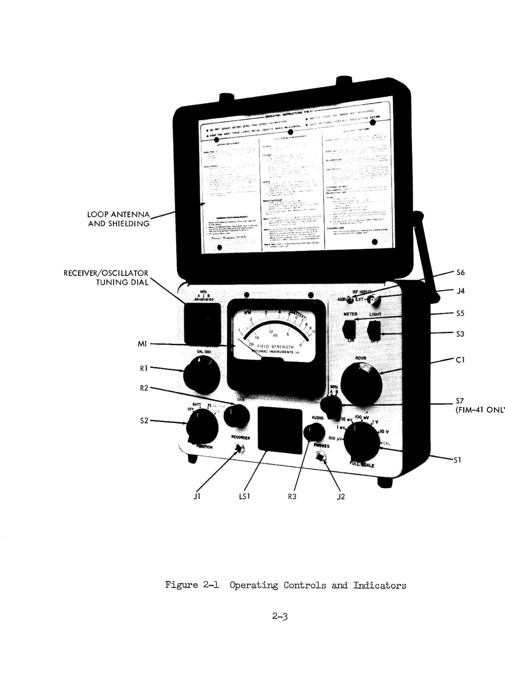
2 2.1 General SECTION 2. OPERATION The FIM-21 and FIM-41 operating controls and indicators are described in this section. Also provided are the basic operating instructions which include battery voltage testing, meter calibration, measuring field strength, and use of these instruments as null detectors for RF Bridge measurements. 2.2 Operating Controls and Indicators All operating controls and indicators are located on the front panel of the FIM-21 and FIM-41 as shown in figure 2-1. Table 2-1 lists these controls and indicators and the associated functions. Table 2-1. Operating Controls and Indicators Control or Indicator FUNCTION selector switch (S2) Function Selects the function to be displayed on the front panel meter and connects battery. OFF - battery disconnected from circuit, and direct connection made across meter terminals to protect meter. BATT - battery output voltage FI CAL TUNE - field strength of antenna input developed from detected output of receiver IF amplifier. CAL Null - compares detector outputs from receiver and calibrating oscillator. FULL SCALE selector switch (S1) Selects the amount of attenuation in RF and IF stages, in 10 to 1 (20 db) ratio steps. The panel is marked with the fullscale direct-reading field strength value for each position. CAL - applies power to calibrating oscillator, and selects 1 volt range of attenuator. AUDIO control and switch (R3) Adjusts level of audio in speaker and headphones. Switch disables audio amplifier in OUT position. 2-1
3 SECTION 2. OPERATION (Cont.) Table 2-1. Operating Controls and Indicators (Cont.) Control or Indicators GAIN control (R2) CAL OSC tuning control (Rl) RCVR tuning control (C1) FIELD-STRENGTH meter (Ml) LIGHT switch (S3) RF INPUT switch MHz switch (FIM-41 only) (S7) METER switch (S5) Function Adjusts gain of receiver by regulating gain of IF amplifier. Fine tunes calibrating oscillator. (Oscillator frequency coarse tuning is pre-set by receiver tuning control.) Tunes receiver and calibrating oscillator by rotating capacitors Cl and C2. Frequency of receiver signal is read on dial. Indicates field strength in volts per meter, in conjunction with full scale switch. Illuminates meter and dial. Switches receiver input to loop antenna (ANT) or external BNC input jack (EXT). Selects frequency band: A..54 to 1.6 MHz B. 1.6 to 5.0 MHz Provides either logarithnic (LOG) or linear (LIN) relation between meter reading and receiver input, the former for use when the meter is to operate in conjunction with recording equipment or when relative measurements of greater than one decade are desired. Replacement of batteries is described in the maintenance section of this manual. 2.3 FIM Calibration The FIM should always be calibrated at the frequency of the signal to be measured. This eliminates any error due to frequency sensitive components in the circuits. Calibrate the meter as follows: 1. Place or hold the field strength meter in a vertical position, with the top surface in a horizontal plane. Open the cover and swing it to a vertical position. 2-2
4
5 2.3 FIM Calibration (Cont.) SECTION 2. OPERATION (Cont.) 2. Rotate the FUNCTION switch to the BATT position and see that the reading is above Rotate the FUNCTION switch to the FI position. 4. Switch LOG-LIN switch to LIN position. 5. Set the FULL SCALE switch to the range which covers the expected value of field strength. 6. Turn on the AUDIO control and tune the RECEIVER dial to the signal to be measured. Use the meter indication to obtain peak tuning, adjusting the GAIN control and FULL SCALE switch, and rotating the instrument to obtain a reading within the range of the meter. Use the audio signal to identify the station. The RCVR Tuning Control has vernier drive for 3/4th of one turn; it changes to direct drive and becomes harder to turn beyond the vernier range. Adjust it so that the desired station falls in the vernier range. 7. Rotate the instrument to obtain reading below 10 mv. In strong fields the meter reading may be reduced below 10 mv by holding the FIM horizontally or by changing RCVR TUNING away from the desired signal by no more than 10 KHz. (This is permissible because the receiver gain variation with frequency is very gradual.) An indistinct dip in the meter reading in Step 8 indicates inadequate reduction of the received signal, or interference. 8. Place the FULL-SCALE switch in the CAL position: adjust CAL OSC Tuning for highest meter reading, or an audio beat note low enough in frequency to be inaudible. (The meter reading should be when the Gain control is properly set.) 9. Rotate FUNCTION switch to CAL NULL position: adjust GAIN control for lowest meter reading. The meter reading should be below Return FUNCTION switch to FI-CAL-TUNE. Retune RCVR tuning for maximum meter reading on the desired signal. The Field Strength Meter is now calibrated at the frequency to which it was originally tuned. 2.4 Measuring Field Strength In use, the field meter is generally held in the hand, or mounted on a tripod or unipod. Of the latter two, the unipod is preferred, since it can be easily rotated, and can remain attached to the instrument. A plate having a hole tapped for a 1/4-20 screw is fastened to the bottom of the case, for attachment to a support. 2-4
6 SECTION 2. OPERATION (Cont.) 2.4 Measuring Field Strength (Cont.) The field meter should always be operated in a vertical position when making field strength measurements. After calibrating as described in the previous section, proceed as follows: 1. Set the FULL SCALE switch to the range approximating the signal strength expected. 2. With the FUNCTION switch set at FI, rotate the unit to orient the loop antenna and obtain maximum deflection on the panel meter, changing the position of the FULL SCALE switch if necessary to keep the panel meter indication on scale. 3. Read the field intensity directly from the panel meter, using the position of the FULL SCALE switch as a guide. For example, with the FULL SCALE switch on 100 mv, a full scale reading of 10 on the meter means 100 millivolts per meter, and a reading of 5.6 indicates a field strength of 56 millivolts per meter. 4. Multiply the reading obtained in step 3 by the K factor for the operating frequency given on the calibration certificate for the instrument. This procedure is followed when it is necessary to make full use of the specified accuracy of the field meter. 5. To de-energize the field meter, rotate the FUNCTION switch to the OFF position. This disconnects the batteries from the circuit. Closing the cover also removes the battery power. 2.5 Measuring Harmonic Ratio in Decibels Field Strength Ratios may be measured directly in decibels by reading the db scale of the meter in conjunction with the FULL-SCALE range indicator. Since each step of the FULL-SCALE switch corresponds to one (1) decade or twenty (20) db, the ratio is determined by the following formula: where: db 1 - db 2 + N x 20 = Ratio in db db 1 = Harmonic field strength db 2 = Fundamental field strength N = Number of FULL SCALE steps between fundamental and harmonic 2-5
7 SECTION 2. OPERATION (Cont.) 2.5 Measuring Harmonic Ratio in Decibels (Cont.) Example: Let us say that we want to measure the field strength and the second and third harmonic suppression of a transmitter with an operating frequency of 1500 KHz. 1. Measure field strength of fundamental as outlined in section 2.4 of this manual; note db scale. Example: 560 mv/m & 5 db. 2. Measure field strength of second harmonic as above at 3.0 MHz. Example: 0.35 mv/m & 9 db. 3. Measure field strength of third harmonic as above at 4.5 MHz. Example: 79 uv/m & 2 db. Calculate harmonic suppression: db 1 - db x N = ratio (db) second harmonic suppression third harmonic suppression = = 64 db = = 77 db It is not the purpose of this manual to describe the techniques of locating radial measurement points and plotting the field data required by the FCC. For this type of information, and for a more detailed description of operating techniques, the user is referred to the current edition of the NAB Handbook. 2.6 R. F. Bridge Measurements The receiver section of the FIM-21 and FIM-41 may be used as a tuned voltmeter for applications such as R. F. Bridge null detection. As a tuned voltmeter, these instruments exhibit an input impedance of 2500 ohms shunted by less than 2 picofarads. To use the FIM as a relative indicator of RF voltage, proceed as follows: 1. RF INPUT switch switch to EXT position 2. METER switch LOG or LIN - the LOG mode is helpful for RF null detection work 3. FUNCTION switch set to FI-CAL TUNE 4. FULL SCALE switch set to l0v position or as requiredfor meter indication 2-6
8 SECTION 2. OPERATION (Cont.) 2.6 R. F. Bridge Measurements (Tuned Voltmeter) (Cont.) Connect RF source to EXT RF input on FIM front panel. Adjust RCVR tuning for desired frequency and highest reading: adjust FULL SCALE switch for an on-scale reading. To calibrate the FIM for absolute voltage measurements; set RCVR tuning to desired frequency with signal source connected to EXT RF input switch settings as in steps 1, 3 & 4 above. The LOG-LIN switch must be set to the LIN position for absolute readings. Switch the RF INPUT switch to ANT and calibrate meter as described in Section 2.3. Return RF INPUT switch to EXT and read meter. The correct voltage is obtained by correlating the meter indication and the FULL SCALE attenuator setting as previously described. IMPORTANT NOTE When operating the FIM as a tuned voltmeter, it is necessary to guard against severe overload at the EXT RF input. For this reason, start all measurements in the l0v FULL SCALE switch position. The maximum input level which can be applied to EXT input without causing damage is 25 volts RMS. 2-7
Model 4402B. Ultra-Pure Sinewave Oscillator 1Hz to 110kHz Typical Distortion of % Serial No. Operating Manual
 Model 4402B Ultra-Pure Sinewave Oscillator 1Hz to 110kHz Typical Distortion of 0.0005% Serial No. Operating Manual 15 Jonathan Drive, Unit 4, Brockton, MA 02301 U.S.A. Tel: (508) 580-1660; Fax: (508) 583-8989
OPERATING AND MAINTENANCE MANUAL
 5Hz to 1MHz WIDE RANGE FULLY AUTOMATIC DISTORTION ANALYZER MODEL 6900B SERIAL NO. OPERATING AND MAINTENANCE MANUAL Unit 4, 15 Jonathan Drive, Brockton, MA 02301-5566 Tel: (508) 580-1660; Fax: (508) 583-8989
MFJ-208 VHF SWR Analyzer
 MFJ-208 VHF SWR Analyzer Thank you for purchasing the MFJ-208 VHF SWR Analyzer. The MFJ-208 gives you a direct readout of your antenna's SWR without the need for formulas or indirect readings. The MFJ-
The 21st Century R-390A/URR Reference Y2K-R3 Edited 7/09: No Technical Changes Chapter 2 - Operation. Page Table Of Contents 2-1
 Edited 7/09: No Technical Changes Chapter 2 - Operation Page Table Of Contents 2-1 2.1 Introduction. 2-2 2.2 Controls and Indicators 2-2 2.3 Operating Instructions And Control Settings 2-9 2.3.1 Pre-operational
MASTR II BASE STATION MHz RECEIVER IF/AUDIO/SQUELCH & RF ASSEMBLY (25 khz/12.5 khz CHANNEL SPACING) Maintenance Manual LBI-38506A
 Maintenance Manual LBI-38506A") A Mobile Communications MASTR II BASE STATION 806-824 MHz RECEIVER IF/AUDIO/SQUELCH & RF ASSEMBLY (25 khz/12.5 khz CHANNEL SPACING) TABLE OF CONTENTS RF ASSEMBLY, MIXER AND IF FILTER BOARD...... LBI-30482
A Mobile Communications MASTR II BASE STATION 806-824 MHz RECEIVER IF/AUDIO/SQUELCH & RF ASSEMBLY (25 khz/12.5 khz CHANNEL SPACING) TABLE OF CONTENTS RF ASSEMBLY, MIXER AND IF FILTER BOARD...... LBI-30482
MASTR II AUXILIARY RECEIVER 19D417546G7 & G8 & ANTENNA MATCHING UNITS 19C321150G1-G2. Maintenance Manual LBI-30766L. Mobile Communications
 L Mobile Communications MASTR II AUXILIARY RECEIVER 19D417546G7 & G8 & ANTENNA MATCHING UNITS 19C321150G1-G2 Printed in U.S.A Maintenance Manual TABLE OF CONTENTS Page SPECIFICATIONS.....................................................
7. Transmitter Radiated Spurious Emissions and Conducted Spurious Emission
 7. Transmitter Radiated Spurious Emissions and Conducted Spurious Emission 7.1 Test Setup Refer to the APPENDIX I. 7.2 Limit According to 15.247(d), in any 100 khz bandwidth outside the frequency band
FREQUENCY AGILE FM MODULATOR INSTRUCTION BOOK IB
 FMT615C FREQUENCY AGILE FM MODULATOR INSTRUCTION BOOK IB1215-02 TABLE OF CONTENTS SECTION SUBJECT 1.0 Introduction 2.0 Installation & Operating Instructions 3.0 Specification 4.0 Functional Description
Operation Manual. Model SG Elenco Precision Wide Band Signal Generator
 99 Washington Street Melrose, MA 02176 Phone 781-665-1400 Toll Free 1-800-517-8431 Visit us at www.testequipmentdepot.com Elenco Precision Wide Band Signal Generator Model SG-9000 Operation Manual CONTENTS
The University of Jordan Mechatronics Engineering Department Electronics Lab.( ) Experiment 1: Lab Equipment Familiarization
 Experiment 1: Lab Equipment Familiarization") The University of Jordan Mechatronics Engineering Department Electronics Lab.(0908322) Experiment 1: Lab Equipment Familiarization Objectives To be familiar with the main blocks of the oscilloscope and
The University of Jordan Mechatronics Engineering Department Electronics Lab.(0908322) Experiment 1: Lab Equipment Familiarization Objectives To be familiar with the main blocks of the oscilloscope and
Exercise 1: RF Stage, Mixer, and IF Filter
 SSB Reception Analog Communications Exercise 1: RF Stage, Mixer, and IF Filter EXERCISE OBJECTIVE DISCUSSION On the circuit board, you will set up the SSB transmitter to transmit a 1000 khz SSB signal
Chino Scientific Instruments Manufacturing
 DIGITAL MICRO OHM METER Chino s made DIGITAL MICRO OHM METER is a compact high reliability 3 ½ digit instrument suitable for measurement of resistivity of copper wires from 70 SWG to 50 SWG resistance
Measurement Procedure & Test Equipment Used
 Measurement Procedure & Test Equipment Used Except where otherwise stated, all measurements are made following the Electronic Industries Association (EIA) Minimum Standard for Portable/Personal Land Mobile
RADIO AMATEUR EXAM GENERAL CLASS
 RAE-Lessons by 4S7VJ 1 CHAPTER-7 RADIO AMATEUR EXAM GENERAL CLASS MEASURMENTS By 4S7VJ 7.1 TEST EQUIPMENT & MEASUREMENTS Correct operation of amateur radio equipment involves measurements to ensure optimum
MFJ-219/219N 440 MHz UHF SWR Analyzer TABLE OF CONTENTS
 MFJ-219/219N 440 MHz UHF SWR Analyzer TABLE OF CONTENTS Introduction...2 Powering The MFJ-219/219N...3 Battery Installation...3 Operation Of The MFJ-219/219N...4 SWR and the MFJ-219/219N...4 Measuring
Frequency range: BAND RANGE MHz MHz
 INSTRUCTION SHEET NO. 20 POWER-MITE PM3 and PM3A DESCRIPTION The Power-Mite 3 and 3A are self-contained CW transceivers covering 40 and 20 meters. The receiver is compromised of a variable oscillator operating
CON NEX HP. OWNER'S MANUAL Full Channel AM/FM Amateur Mobile Transceiver TABLE OF CONTENTS TUNING THE ANTENNA FOR OPTIMUM S.W.R..
 TABLE OF CONTENTS PAGE SPECIFICATIONS... 2 INSTALLATION... 3 LOCATION... 3 CON NEX - 4300HP MOUNTING THE RADIO... 3 IGNITION NOISE INTERFERENCE... 4 ANTENNA... 4 TUNING THE ANTENNA FOR OPTIMUM S.W.R..
OBJECTIVES EQUIPMENT LIST
 1 Reception of Amplitude Modulated Signals AM Demodulation OBJECTIVES The purpose of this experiment is to show how the amplitude-modulated signals are demodulated to obtain the original signal. Also,
OPERATION MANUAL. Model 1010 TE Survey Meter. August Health Physics Instruments 330 South Kellogg Ave, Suite D Goleta, CA 93117
 OPERATION MANUAL Model 1010 TE Survey Meter August 1998 Health Physics Instruments 330 South Kellogg Ave, Suite D Goleta, CA 93117 GENERAL INFORMATION This instrument is manufactured in the United States
MEASUREMENT PROCEDURE AND TEST EQUIPMENT USED
 MEASUREMENT PROCEDURE AND TEST EQUIPMENT USED Except where otherwise stated, all measurements are made following the Electronic Industries Association (EIA) Minimum Standard for Portable/Personal Land
Radio Station Setup and Electrical Principles
 Radio Station Setup and Electrical Principles Covers sections: T4A-T5D Seth Price, N3MRA February 20, 2016 Outline 4.1 Station Setup 4.2 Operating Controls 4.3 Electronic Principles 4.4 Ohm s Law 4.5 Power
E-200D ALIGNMENT. See the end of the procedure for the location of the calibration points. EQUIPMENT REQUIRED
 E-200D ALIGNMENT NOTE: This is not an official B&K alignment procedure. This procedure was created by experimenting with an E-200D. However when this procedure is followed, the resulting calibration should
A GOOD REGENERATIVE RECEIVER WITH SIMPLE FINE TUNING (2008)
") A GOOD REGENERATIVE RECEIVER WITH SIMPLE FINE TUNING (2008) A good SSB-CW-AM regenerative receiver with a fine tuning by moving the wooden stick with a grounded piece of PCB towards the coil. A good regenerative
A GOOD REGENERATIVE RECEIVER WITH SIMPLE FINE TUNING (2008) A good SSB-CW-AM regenerative receiver with a fine tuning by moving the wooden stick with a grounded piece of PCB towards the coil. A good regenerative
ELECTRIC FIELD PROBE ANTENNA MODEL PEF-10A. 20 Hz 1 MHz
 INSTRUCTION MANUAL ELECTRIC FIELD PROBE ANTENNA MODEL PEF-10A 20 Hz 1 MHz INSTRUCTION MANUAL THIS INSTRUCTION MANUAL AND ITS ASSOCIATED INFORMATION IS PRO- PRIETARY. UNAUTHORIZED REPRO- DUCTION IS FORBIDDEN.
Ave output power ANT 1(dBm) Ave output power ANT 2 (dbm)
 Ave output power ANT 2 (dbm)") Page 41 of 103 9.6. Test Result The test was performed with 802.11b Channel Frequency (MHz) power ANT 1(dBm) power ANT 2 (dbm) power ANT 1(mW) power ANT 2 (mw) Limits dbm / W Low 2412 7.20 7.37 5.248 5.458
Page 41 of 103 9.6. Test Result The test was performed with 802.11b Channel Frequency (MHz) power ANT 1(dBm) power ANT 2 (dbm) power ANT 1(mW) power ANT 2 (mw) Limits dbm / W Low 2412 7.20 7.37 5.248 5.458
Electronic Pipeline Technology
 Pipe and Cable Locator Pearson Holiday Detector Model EPT- 1000 Electronic Pipeline Technology Electronic Pipeline Technology 26 Palomino Drive, Richmond Hill, Ontario, Canada, L4C 0P8 Tel: (905) 918-0025
LBI-30398N. MAINTENANCE MANUAL MHz PHASE LOCK LOOP EXCITER 19D423249G1 & G2 DESCRIPTION TABLE OF CONTENTS. Page. DESCRIPTION...
 MAINTENANCE MANUAL 138-174 MHz PHASE LOCK LOOP EXCITER 19D423249G1 & G2 LBI-30398N TABLE OF CONTENTS DESCRIPTION...Front Cover CIRCUIT ANALYSIS... 1 MODIFICATION INSTRUCTIONS... 4 PARTS LIST AND PRODUCTION
Matric Limited Hill City Road R.R. #1 Box 421A Seneca, PA 16346
 FCC CERTIFICATION TEST REPORT for Hill City Road R.R. #1 Box 421A Seneca, PA 16346 FCC ID: K5B-TP105 May 14, 2001 Revised: June 18, 2001 WLL PROJECT #: 6182X This report may not be reproduced, except in
18-CHANNEL MOBILE CB TRANSCEIVER MODEL CB-845
 18-CHANNEL MOBILE CB TRANSCEIVER MODEL CB-845 INSTRUCTION HANDBOOK RAll JEFFERSOn CITIZEN BAND RADIO MESSAGE TO THE OWNER CONGRATULATIONS! As the new owner of Ray Jefferson Model CB-845 CB Mobile Transceiver,
DSTS-3B DEPTHSOUNDER TEST SET OPERATOR S MANUAL
 Page 1 1.0 INTRODUCTION DSTS-3B DEPTHSOUNDER TEST SET OPERATOR S MANUAL The DSTS-3B is a full-featured test set designed for use with all types of echo sounders from small flashers to large commercial
DX AM FM SSB CW PA Amateur Base Station Transceiver OWNER S MANUAL RX / TX 2 4 POWER NF CHANNEL MODE RF POWER OFF CAL OFF OFF CALIBRATE
 1 2 3 6 4050 ULA 6070 TI 80 90 100 9 DX 2517 2517 RX / TX 0 2 4 SWR WATTS SET 81012 22 1 010 3 2030 5 MOD 7 ON dbover 9 SIGNAL +20 +40+60 PA FM AM USB LSB CW POWER ON SWR NB / ANL R.BEEP +10KHz NF CHANNEL
REDSUN PF2100 PLL RADIO OPERATING MANUAL
 REDSUN PF2100 PLL RADIO OPERATING MANUAL TRANSLATED BY LIYPN ALL RIGHTS RESERVED JUNE 2006 (We are the copyright holder of this manual in English. Please do NOT distribute this manual in any form nor post
ERICSSONZ LBI-30398P. MAINTENANCE MANUAL MHz PHASE LOCKED LOOP EXCITER 19D423249G1 & G2 DESCRIPTION TABLE OF CONTENTS
 MAINTENANCE MANUAL 138-174 MHz PHASE LOCKED LOOP EXCITER 19D423249G1 & G2 TABLE OF CONTENTS Page DESCRIPTION... Front Cover CIRCUIT ANALYSIS...1 MODIFICATION INSTRUCTIONS...4 PARTS LIST...5 PRODUCTION
HOMEBREW Q-MULTIPLIER
 HOMEBREW Q-MULTIPLIER This circuit can boost the signal strength in your receiver by 1 or 2 S-units, giving approximately 10 db gain. A Q-multiplier amplifies the Q of the first IF transformer so that
2014 MFJ ENTERPRISES, INC.
 Model MFJ-209C INSTRUCTION MANUAL CAUTION: Read All Instructions Before Operating Equipment MFJ ENTERPRISES, INC. 300 Industrial Park Road Starkville, MS 39759 USA Tel: 662-323-5869 Fax: 662-323-6551 VERSION
TABLE OF CONTENTS APPLICANT: FLYING DRAGON DEVELOPMENT LTD. FCC ID: PNX-FD383-SV-01 TEST REPORT CONTAINING:
 TABLE OF CONTENTS APPLICANT: FLYING DRAGON DEVELOPMENT LTD. FCC ID: PNX-FD383-SV-01 TEST REPORT CONTAINING: PAGE 1...TEST EQUIPMENT LIST & TEST PROCEDURE PAGE 2...TEST PROCEDURE CONTD. PAGE 3...RADIATION
UNIT-3. Electronic Measurements & Instrumentation
 UNIT-3 1. Draw the Block Schematic of AF Wave analyzer and explain its principle and Working? ANS: The wave analyzer consists of a very narrow pass-band filter section which can Be tuned to a particular
User s Manual For PAMS. Portable Attenuation Measurement System /
 User s Manual For PAMS Portable Attenuation Measurement System www.praxsym.com 217/897-1744 2 Contents I. Introduction..... 3 1.0 General Information... 4 1.1 Equipment Purpose...4 1.2 Equipment List...4
CMA-100. Counter Measures Amplifier. Owner s Guide
 CMA-100 Counter Measures Amplifier Owner s Guide INTRODUCTION: Thank you for purchasing the CMA-100 Countermeasures Amplifier. When doing a Counter-surveillance investigation, it is important to analyze
MFJ-249B HF/VHF SWR ANALYZER
 TABLE OF CONTENTS MFJ-249B... 2 Introduction... 2 Powering The MFJ-249B... 3 Battery Installation... 3 Alkaline Batteries... 3 NiCd Batteries... 4 Power Saving Mode... 4 Operation Of The MFJ-249B...5 SWR
APPENDIX D DISCUSSION OF ELECTRONIC INSTRUMENTS
 APPENDIX D DISCUSSION OF ELECTRONIC INSTRUMENTS DC POWER SUPPLIES We will discuss these instruments one at a time, starting with the DC power supply. The simplest DC power supplies are batteries which
RF Emissions Test Report To Determine Compliance With: FCC, Part 15 Rules and Regulations
 RF Emissions Test Report To Determine Compliance With: FCC, Part 15 Rules and Regulations Model numbers: HT130022 Rev. B. December 17, 2002 Manufacturer: HQ, Inc. 210 9th Steet Drive Palmetto, FL 34221
Interference & Suppression Page 59
 INTERFERENCE Interference & Suppression Page 59 Front-End Overload, Cross-Modulation What is meant by receiver overload? Interference caused by strong signals from a nearby transmitter What is one way
MIL-STD June 1956 SUPERSEDING MIL-A-18123(SHIPS) 1 August 1954 MILITARY STANDARD
 1 August 1954 MILITARY STANDARD") SUPERSEDING MIL-A-18123(SHIPS) 1 August 1954 MILITARY STANDARD ATTENUATION MEASUREMENTS FOR ENCLOSURES, ELECTROMAGNETIC SHIELDING, FOR ELECTRONIC TEST PURPOSES, METHOD OF UNITED STATES GOVERNMENT PRINTING
SUPERSEDING MIL-A-18123(SHIPS) 1 August 1954 MILITARY STANDARD ATTENUATION MEASUREMENTS FOR ENCLOSURES, ELECTROMAGNETIC SHIELDING, FOR ELECTRONIC TEST PURPOSES, METHOD OF UNITED STATES GOVERNMENT PRINTING
Electrical Fundamentals and Basic Components Chapters T2, T3, G4
 Electrical Fundamentals and Basic Components Chapters T2, T3, G4 Some Basic Math, Electrical Fundamentals, AC Power, The Basics of Basic Components, A Little More Component Detail, Reactance and Impedance
Amateur Radio Examination EXAMINATION PAPER No. 275 MARKER S COPY
 01-6-(d) An Amateur Station is quoted in the regulations as a station: a for training new radio operators b using amateur equipment for commercial purposes c for public emergency purposes d in the Amateur
2006 MFJ ENTERPRISES, INC.
 Model MFJ-207 INSTRUCTION MANUAL CAUTION: Read All Instructions Before Operating Equipment MFJ ENTERPRISES, INC. 300 Industrial Park Road Starkville, MS 39759 USA Tel: 662-323-5869 Fax: 662-323-6551 VERSION
FCC PART 80 & 90 TEST REPORT
 849 NW STATE ROAD 45 NEWBERRY, FL 32669 USA PH: 888.472.2424 OR 352.472.5500 FAX: 352.472.2030 EMAIL: INFO@TIMCOENGR.COM HTTP://WWW.TIMCOENGR.COM FCC PART 80 & 90 TEST REPORT APPLICANT FCC ID MODEL NUMBER
MODEL PD PEARSON DETECTOR
 MODEL PD PEARSON DETECTOR FIVE SECTIONS of QUICK INFORMATION I. Model PD Functions II. Operation Methods III. Apparatus IV. Instructions for Unpacking & Inspection V. Operating Instructions TINKER & RASOR
TECHNICAL MANUAL CALIBRATION PROCEDURE FOR MULTIMETERS
 TECHNICAL MANUAL CALIBRATION PROCEDURE FOR MULTIMETERS Distribution Statement C - Distribution authorized to U. S. Government agencies and their contractors for official use or for administrative or operational
Test Report. Prepared for: Becker Avionics, Inc. Model: TG Description: Aeronautical basestation radio used for emergencies
 Test Report Prepared for: Becker Avionics, Inc Model: TG660-50 Description: Aeronautical basestation radio used for emergencies Serial Number: 10001, 10002 FCC ID: 2AHX9TG660 To FCC Part 87 Date of Issue:
NTE7047 Integrated Circuit TV Color Small Signal Sub System
 NTE7047 Integrated Circuit TV Color Small Signal Sub System Features: Vision IF Amplifier with Synchronous Demodulator Automatic Gain Control (AGC) Detector Suitable for Negative Modulation AGC Tuner Automatic
The G4EGQ RAE COURSE Lesson 9 Transmitters Lesson 8 looked at a simple transmitter exciter comprising of oscillator, buffer and multiplier stages.
 Lesson 8 looked at a simple transmitter exciter comprising of oscillator, buffer and multiplier stages. The power amplifier The output from the exciter is usually very low and it is necessary to amplify
Hendricks QRP Kits BITX20A to BITX17A Conversion Instructions
 Hendricks QRP Kits BITX20A to BITX17A Conversion Instructions 30 November 2008 Converting your BITX20A Kit to a BITX17A Kit is not all that complex. It only requires that you change crystals and some resonance
Model 1791 VHF Radio User's Manual
 Model 79 VHF Radio User's Manual ALL WEATHER INC 65 NATIONAL DRIVE SACRAMENTO, CA 95834 WWW.ALWEATHERINC.COM 79 VHF RADIO USER'S MANUAL CONTENTS INTRODUCTION... Description... Transmitter Module... Power
CAVITY TUNING. July written by Gary Moore Telewave, Inc. 660 Giguere Court, San Jose, CA Phone:
 CAVITY TUNING July 2017 -written by Gary Moore Telewave, Inc 660 Giguere Court, San Jose, CA 95133 Phone: 408-929-4400 1 P a g e Introduction Resonant coaxial cavities are the building blocks of modern
LBI-31807D. Mobile Communications MASTR II REPEATER CONTROL PANEL 19B234871P1. Maintenance Manual. Printed in U.S.A.
 D Mobile Communications MASTR II REPEATER CONTROL PANEL 19B234871P1 Maintenance Manual Printed in U.S.A. This page intentionally left blank 13 PARTS LIST 12 PARTS LIST LBI-31807 11 PARTS LIST 10 SCHEMATIC
6.101 Project Proposal April 9, 2014 Kayla Esquivel and Jason Yang. General Outline
 6.101 Project Proposal April 9, 2014 Kayla Esquivel and Jason Yang General Outline We will build a superheterodyne AM Radio Receiver circuit that will have a bandwidth of the entire AM spectrum, and whose
PRACTICE. Amateur Radio Operator Certificate Examination. Advanced Qualification
 Amateur Radio Operator ertificate Examination Advanced Qualification 2019-04-03 To pass this exam, you must correctly answer 35 out of 50 questions Exam Number: 115916 1. (A-007-008-002) Why would one
INTEGRATED CIRCUITS DATA SHEET. TDA7021T FM radio circuit for MTS. Product specification File under Integrated Circuits, IC01
 INTEGRATED CIRCUITS DATA SHEET File under Integrated Circuits, IC01 May 1992 GENERAL DESCRIPTION The integrated radio receiver circuit is for portable radios, stereo as well as mono, where a minimum of
Electronic Instrument Disadvantage of moving coil meter Low input impedance High loading error for low-voltage range voltmeter
 EIE 240 Electrical and Electronic Measurement Class 6, February 20, 2015 1 Electronic Instrument Disadvantage of moving coil meter Low input impedance High loading error for low-voltage range voltmeter
N3ZI Kits General Coverage Receiver, Assembly & Operations Manual (For Jun 2011 PCB ) Version 3.33, Jan 2012
 Version 3.33, Jan 2012") N3ZI Kits General Coverage Receiver, Assembly & Operations Manual (For Jun 2011 PCB ) Version 3.33, Jan 2012 Thank you for purchasing my general coverage receiver kit. You can use the photo above as a
N3ZI Kits General Coverage Receiver, Assembly & Operations Manual (For Jun 2011 PCB ) Version 3.33, Jan 2012 Thank you for purchasing my general coverage receiver kit. You can use the photo above as a
VHF LAND MOBILE SERVICE
 RFS21 December 1991 (Issue 1) SPECIFICATION FOR RADIO APPARATUS: VHF LAND MOBILE SERVICE USING AMPLITUDE MODULATION WITH 12.5 khz CARRIER FREQUENCY SEPARATION Communications Division Ministry of Commerce
PRACTICE. Amateur Radio Operator Certificate Examination. Advanced Qualification
 Innovation, Science and Economic Development Canada Innovation, Sciences et Développement économique Canada Amateur Radio Operator Certificate Examination Advanced Qualification 2018-06-30 To pass this
DEPARTMENT OF THE ARMY TECHNICAL BULLETIN
 *TB 9-6625-1914-24 DEPARTMENT OF THE ARMY TECHNICAL BULLETIN CALIBRATION PROCEDURE FOR SPECTRUM ANALYZER, IF, LF, AND RF PLUG-IN UNITS, HEWLETT-PACKARD, MODELS 8552( ), 8553( ), 8554( ), 8555( ), AND 8556(
EXHIBIT 3 : FCC (c) (TEST DATA) AND FCC (MEASUREMENT PROCEDURES) INTRODUCTION TO TRANSMITTER MEASUREMENTS, Part 2.
 (TEST DATA) AND FCC (MEASUREMENT PROCEDURES) INTRODUCTION TO TRANSMITTER MEASUREMENTS, Part 2.") EXHIBIT 3 : FCC 2.1033(c) (TEST DATA) AND FCC 2.1041 (MEASUREMENT PROCEDURES) INTRODUCTION TO TRANSMITTER MEASUREMENTS, Part 2.1033(c)(14) Exhibits 4 through 9 on the following pages present the required
EXHIBIT 3 : FCC 2.1033(c) (TEST DATA) AND FCC 2.1041 (MEASUREMENT PROCEDURES) INTRODUCTION TO TRANSMITTER MEASUREMENTS, Part 2.1033(c)(14) Exhibits 4 through 9 on the following pages present the required
: REMOTE CONTROL TRANSMITTER : FEGO PRECISION INDUSTRIAL CO., LTD.
 Product : REMOTE CONTROL TRANSMITTER Manufacture : FEGO PRECISION INDUSTRIAL CO., LTD. FCC ID : M8CRL202 Model : BC4162D Report No. : MLT0406P15001 Test Date : 06/07/2004 Test By Max Light Technology Co.,Ltd.
UNIT 2. Q.1) Describe the functioning of standard signal generator. Ans. Electronic Measurements & Instrumentation
 Describe the functioning of standard signal generator. Ans. Electronic Measurements & Instrumentation") UNIT 2 Q.1) Describe the functioning of standard signal generator Ans. STANDARD SIGNAL GENERATOR A standard signal generator produces known and controllable voltages. It is used as power source for the
UNIT 2 Q.1) Describe the functioning of standard signal generator Ans. STANDARD SIGNAL GENERATOR A standard signal generator produces known and controllable voltages. It is used as power source for the
SP980. Cordless Stereo 863MHZ. Speaker System. User s Manual INTRODUCTION FEATURES. Please read before using the equipment
 SP980 Cordless Stereo 863MHZ Speaker System INTRODUCTION This 863 MHz stereo wireless speaker system uses latest wireless technology that enables you to enjoy music and TV sound anywhere inside or outside
Swept Return Loss & VSWR Antenna Measurements using the Eagle Technologies RF Bridge
 Swept Return Loss & VSWR Antenna Measurements using the Eagle Technologies RF Bridge April, 2015 Page 1 of 7 Introduction Return loss and VSWR are a measure of the magnitude of a transmitted RF Signal
SENSOTEC, INC Arlingate Lane Columbus, Ohio Phone (614) Facsimile (614) Toll Free Free (800)
 Facsimile (614) Toll Free Free (800)") SENSOTEC, INC. 2080 Arlingate Lane Columbus, Ohio 43228 Phone (614) 850-5000 Facsimile (614) 850-1111 Toll Free Free (800) 848-6564 Instructions for the SA-BII (Switchable Gain) MODULE 008-0122-00 008-0122-00
SENSOTEC, INC. 2080 Arlingate Lane Columbus, Ohio 43228 Phone (614) 850-5000 Facsimile (614) 850-1111 Toll Free Free (800) 848-6564 Instructions for the SA-BII (Switchable Gain) MODULE 008-0122-00 008-0122-00
Application Note: Swept Return Loss & VSWR Antenna Measurements using the Eagle Technologies RF Bridge
 : Swept Return Loss & VSWR Antenna Measurements using the Eagle Technologies RF Bridge FCT-1008A Introduction Return loss and VSWR are a measure of the magnitude of a transmitted RF Signal in relation
BRIDGEABLE MOSFET POWER AMPLIFIERS BZA-2290/BZA-2390 BZA-2490/BZA-4190 OWNER'S MANUAL
 BRIDGEABLE MOSFET POWER AMPLIFIERS BZA-2290/BZA-2390 BZA-2490/BZA-4190 OWNER'S MANUAL Table of Contents Table of Contents 1 2 3~7 8 9~11 9 10~11 Troubleshooting 12 Wiring 13 Introduction & Features Introduction
Synthesized Base Station Transmitter
 BST-25 OPERATOR S MANUAL (216 MHz) Synthesized Base Station Transmitter 357 West 2700 South Salt Lake City, Utah 84115 Phone: (800) 496-3463 Fax: (801) 484-6906 http://www.comtek.com INTRODUCTION BST-25
Operation Manual. SlJPER ST AR Channel Mobile 5-Mode Transceiver -----~- --:.. KTSS200NXX ,, I
 Operation Manual!.,, SlJPER ST AR 2000 200 Channel Mobile 5-Mode Transceiver -----~- --:.. KTSS200NXX General Description l Frequency/Channel Chart The Super Star -2000 is a combination transmitter-receiver
ig-5282 spec.txt IG-5282 Audio Generator
 IG-5282 Audio Generator ig-5282 spec.txt The Heathkit IG-5282 Audio Generator is an audio frequency signal generator. It provides sine wave and square wave signals that may be used as a signal source for
Exercise MM About the Multimeter
 Exercise MM About the Multimeter Introduction Our world is filled with devices that contain electrical circuits in which various voltage sources cause currents to flow. Electrical currents generate heat,
hallicrafters PERFORMANCE SPECIFICATIONS MODEL: SR-2000 LATEST REVISION: 18 JAN 66 Code ident # Specification #
 hallicrafters PERFORMANCE SPECIFICATIONS MODEL: SR-2000 LATEST REVISION: 18 JAN 66 Code ident # 26916 Specification # 093-002154 I. GENERAL A. Power input 117V 50-60 cycles from a source capable of delivering
360mm (14-3/16 ) x 224mm (8-13/16 ) x 67mm (2-5/8 )
 x 224mm (8-13/16 ) x 67mm (2-5/8 )") EN-41400 (4 Channel) EN-21200 (2 Channel) Class Class-AB Class-AB Power 1400 Watts 1200 Watts Frequency Response 10Hz - 42kHz 10Hz - 45kHz Dimensions 360mm (14-3/16 ) x 224mm (8-13/16 ) x 67mm (2-5/8 )
EN-41400 (4 Channel) EN-21200 (2 Channel) Class Class-AB Class-AB Power 1400 Watts 1200 Watts Frequency Response 10Hz - 42kHz 10Hz - 45kHz Dimensions 360mm (14-3/16 ) x 224mm (8-13/16 ) x 67mm (2-5/8 )
1.0 General Description
 1.0 General Description Figure 1 - Plug-N-Play Noise Blanker for the Collins 75S-1 Series The Collins Noise Blanker is designed to be a Plug-N-Play accessory for the Collins 75S-1 series. The Noise Blanker
Experiment 1: Instrument Familiarization (8/28/06)
") Electrical Measurement Issues Experiment 1: Instrument Familiarization (8/28/06) Electrical measurements are only as meaningful as the quality of the measurement techniques and the instrumentation applied
Electrical Measurement Issues Experiment 1: Instrument Familiarization (8/28/06) Electrical measurements are only as meaningful as the quality of the measurement techniques and the instrumentation applied
2005 MFJ ENTERPRISES, INC.
 Model MFJ-209 INSTRUCTION MANUAL CAUTION: Read All Instructions Before Operating Equipment MFJ ENTERPRISES, INC. 300 Industrial Park Road Starkville, MS 39759 USA Tel: 662-323-5869 Fax: 662-323-6551 VERSION
ANALOG COMMUNICATION
 ANALOG COMMUNICATION TRAINING LAB Analog Communication Training Lab consists of six kits, one each for Modulation (ACL-01), Demodulation (ACL-02), Modulation (ACL-03), Demodulation (ACL-04), Noise power
Installation Instructions
 Installation Instructions Audio Output Transformer for NGX Jukebox Kit #22180806 These instructions outline the procedures to install and connect an Audio Output Transformer to the NGX Jukebox. Tools and
AK-18G Antenna Kit Operation Manual
 AK-18G Antenna Kit Operation Manual 1 TABLE OF CONTENTS WARRANTY 3 INTRODUCTION 4 GENERAL INFORMATION 5 OPTIONAL EQUIPMENT 8 FORMULAS 9 MAINTENANCE 10 2 WARRANTY INFORMATION A.H. Systems Inc., warrants
The Harvard Research Carrier Signal Conditioner User s Manual
 The Harvard Research Carrier Signal Conditioner User s Manual TABLE OF CONTENTS SECTION TITLE PAGE I GENERAL INFORMATION INTRODUCTION 1.1 SPECIFICATIONS 1.1 II INSTALLATION 2.1 GENERAL 2.1 2.2 INITIAL
Balanced Line Driver & Receiver
 Balanced Line Driver & Receiver Rod Elliott (ESP) Introduction Sometimes, you just can't get rid of that %$#*& hum, no matter what you do. Especially with long interconnects (such as to a powered sub-woofer),
Yaesu FT-8800R Alignment
 DUAL BAND FM TRANSCEIVER Introduction and Precautions The FT-8800R has been carefully aligned at the factory for the specified performance across the 144 MHz and 430 MHz amateur bands. Realignment should
Hallicrafters SX-88 Owners Manual
 Hallicrafters SX-88 Owners Manual Images and text excerpted from original Hallicrafters literature. Section 1. General Description The Hallicrafters SX-88 represents the ultimate in precision communications
CMA-100. User Manual. Counter Measures Amplifier
 CMA-100 Counter Measures Amplifier User Manual Research Electronics International, LLC 455 Security Drive, Cookeville, TN 38506 U.S.A. (800) 824-3190 (US Only) +1 931-537-6032 www.reiusa.net Copyright
TIMCO ENGINEERING INC.
 Test Report Product Name: FM EXCITER - TRANSMITTER Applicant: NiCOM USA, INC. 2626 SOUTHPORT WAY SUITE B NATIONAL CITY, CA 91950 Date Receipt: DECEMBER 29, 2003 Date Tested: JANUARY 13, 2004 COVER SHEET
Western Electric D V a c u u m T u b e
 284D Western Electric 2 8 4 D V a c u u m T u b e Classification Fiiamentary air-cooied triode The tube is designed primarily for use as an audio-frequency amplifier or modulator and may be used as a replacement
ACCESSORY CIRCUITS ALIGNMENT
 UNIDEN 22 ACCESSOY CICUITS ALIGNMENT 1. NOISE BLANKE Adjustment 11. Test Equipment equired (1) DC Voltage Meter 12. Adjustment Procedures. (1) Set MODE SWITCH to USB, and recive 14.2 Mhz. (2) Activate
Experiment 1: Instrument Familiarization
 Electrical Measurement Issues Experiment 1: Instrument Familiarization Electrical measurements are only as meaningful as the quality of the measurement techniques and the instrumentation applied to the
RECEIVER TEST OSCILLATOR Rev G, January 16, 2018 Copyright 2018, Elecraft, Inc., All Rights Reserved
 E L E C R A F T XG RECEIVER TEST OSCILLATOR Rev G, January 6, 08 Copyright 08, Elecraft, Inc., All Rights Reserved Introduction The Elecraft XG is a crystal oscillator with accurate µv and 50 µv output
LBI-31564A. Mobile Communications. DELTA - SX MHz RADIO COMBINATIONS (NEGATIVE GROUND ONLY) Maintenance Manual
 Maintenance Manual") A Mobile Communications DELTA - SX 136-174 MHz RADIO COMBINATIONS (NEGATIVE GROUND ONLY) Maintenance Manual TABLE OF CONTENTS MILITARY AND SYSTEM SPECIFICATIONS................................. 2-3 COMBINATION
A Mobile Communications DELTA - SX 136-174 MHz RADIO COMBINATIONS (NEGATIVE GROUND ONLY) Maintenance Manual TABLE OF CONTENTS MILITARY AND SYSTEM SPECIFICATIONS................................. 2-3 COMBINATION
Test Report. Applicant ASUSTeK COMPUTER INC. 4F, No. 150, Li-Te Rd., Peitou, Taipei, Taiwan. Date of Receipt Jan. 28, Issued Date Mar.
 Test Report Product Name Model No. FCC ID. IC ID. WPC Qi 1.1/1.0 compliance wireless charging micro-usb box Wireless Charger MSQ-ASUSWLCHARGER 3568A-ASWLCHARGER Applicant ASUSTeK COMPUTER INC. Address
Model Operating Manual
 Model 7500 DC to 1MHz Wideband Power Amplifier Operating Manual Copyright 2004. All rights reserved. Contents of this publication may not be reproduced in any form without the written permission of Krohn-Hite
Building the Sawdust Regenerative Receiver
 Building the Sawdust Regenerative Receiver Introduction The Sawdust is a super regenerative receiver using the basic Armstrong design architecture. The receiver uses one toroidal transformer to provide
RITEK RIT for Collins KWM-2/2A 10/01/2002
 RITEK RIT for Collins KWM-2/2A 10/01/2002 The RITEK RIT (receiver incremental tuning) control was developed for KWM-2/2A in 1992 to "clarify" received signals differing from the transmit frequency indicated