A GOOD REGENERATIVE RECEIVER WITH SIMPLE FINE TUNING (2008)
|
|
|
- Elinor Kelly
- 5 years ago
- Views:
Transcription

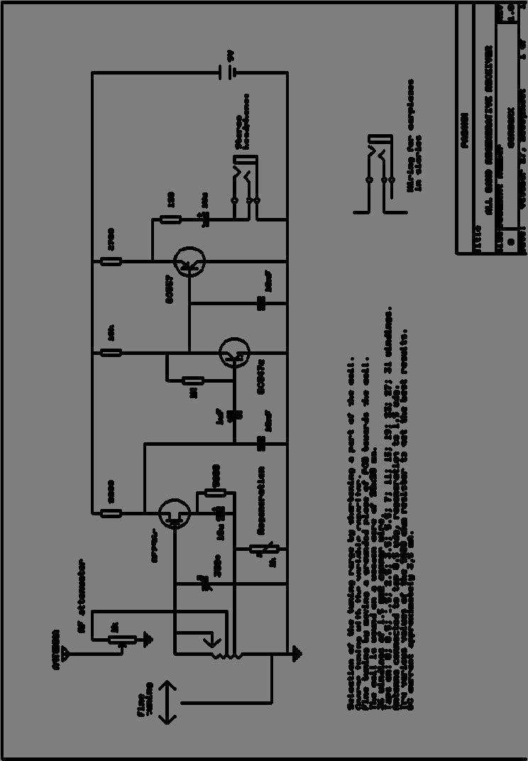
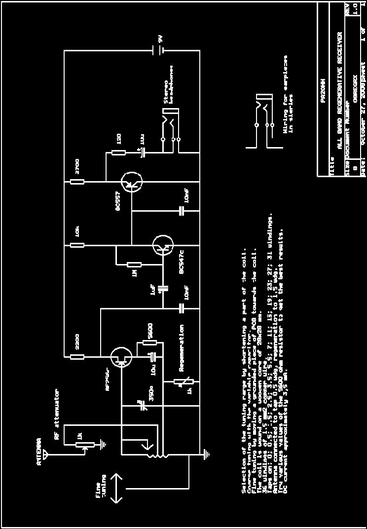
1 A GOOD REGENERATIVE RECEIVER WITH SIMPLE FINE TUNING (2008) A good SSB-CW-AM regenerative receiver with a fine tuning by moving the wooden stick with a grounded piece of PCB towards the coil. A good regenerative receiver When you add an LF stage and a fine tuning to the simple receiver with only one FET, you will have a much better regenerative receiver. No audio transformer is required anymore, the audio signal is much stronger and you do not need to use special, sensitive headphones anymore. By adding a simple fine tuning, tuning to SSB stations is not a problem at all, not even on the high 18MHz band, reception of that band is very good with this receiver! Of course you cannot compare this receiver with a real good commercial receiver. But you can experience how it is to work with such a historical regenerative receiver. Controlling the receiver is very special. To adjust the feedback, continuously retune a little to correct the frequency drift, to adjust
2 the RF attenuator. That was exactly how they did it in the past! And you will be astonished about how much you can receive with it! On all bands from 1.8 MHz to 18 MHz, many amateurs can be heard with a wire antenna of 5 meter! It is nice to play with it. To rotate the tuning knob slowly or very fast, and to be surprised about the strange signals that you will hear. Listening to remote broadcast stations and to be astonished about how strong these broadcast stations are compared with the signals of amateurs. With this receiver, you can receive the whole shortwave band up to 30 MHz, and even a part of the medium wave. But above 21 MHz, it does not work very good anymore, depending on the construction and the used FET, it might be that the receiver does not generate anymore at these high frequencies. A simple and cheap construction We want to make this receiver to experience how it was in the past, when radio operators had to work with such simple regenerative receivers. But we want to use easily obtainable parts and of course it should be cheap. Therefore, only one variable capacitor is used, it is also the only RF component that has to be bought. For the antenna coupling and the regeneration, potentiometers are used. And the fine tuning is also made without a variable capacitor. This receiver is a nice home brew project. It is so simple, that the construction of it cannot go wrong. Diagram of the regenerative receiver. big diagram Description The heart of the circuit is the FET BF256c (c type has the highest gain). By means of the 5600 ohm resistor, it works in the non- linear part of the Id/Vgs characteristic. Experiment with that value in your receiver for the best performance. The 10uF capacitor is for decoupling of the resistor, also for high


3 frequencies. Perhaps that you need to add an extra 0.1uF capacitor in parallel for decoupling of the RF frequencies but I did not hear any difference. The regeneration is controlled by means of the 1k potentiometer. Adjust it for maximum sensitivity. In the original simple receiver, 10k was used, but 1k is a much better value. A transistor BC547c amplifies the LF signal and the BC557 is the replacement of the audio transformer. It has a high impedance input and a low impedance output. Sensitivity and sound level are good. If you want more audio signal, then you can connect both pieces of the headphones in series! Quite often, the signals are too strong and then some RF attenuation is necessary. We can do that with the 1k adjustable potentiometer with a small screwdriver. Of course it is better to use a normal potentiometer with a knob at the front panel. This potentiometer is also the only volume control in the receiver. The coil in use for 80 meter. for the other bands, a part of the coil is shortened. The coil The coil is wound with 1,5mm (16AWG) solid copper wire (black) on a square strip of wood of 28x28 mm. The windings with a tap are pulled upwards a little and the isolation is removed. The short from the top are connected to these taps with a wire with a crocodile clip. I used a standard cord for that, but the wires are not soldered to the clip. SOLDER THIS WIRE AT THE BACK SIDE TO THE CLIP!! Otherwise you will have some contact resistance between the clip and the wire after a few years. The correct tap is determined experimentally. The receiver is very sensitive and it is not necessary to look for the best tap for the antenna and source. They are permanently connected to 0.5 windings and 1.5 windings. But for 10 meter, the antenna has to be connected to a lower tap. So it is better to have a switch for the selection of 2 taps for the antenna. The coil in use for 20 and 30 meter.


4 Coarse tuning with the variable capacitor Coarse tuning can be done with the variable capacitor. The various shortwave bands are selected by shortening a part of the coil. And 160 meter is selected by adding a capacitor in parallel to the coil. I use the second part for the variable capacitor for that purpose. The coil in use for 160 meter. An extra capacitor is added, I use the second part of the variable capacitor. Fine tuning The fine tuning by moving your hand towards the coil is quite tiring. But we have a simple solution for that. A wooden stick with grounded piece of PCB that rotates around a screw. Drill a hole with the size of the screw in the stick and fix the screw with nut so that it moves smoothly. With this fine tuning, you can tune almost the whole CW or SSB part of the 40 meter band! You can change this frequency range by changing the size of the PCB. Fine tuning with the stick with grounded piece of PCB. It rotates around the screw with nut on the leftside.

5 Close to the coil, the fine tuning works more coarse then when it is far from the coil. This position is good for the higher bands. Supply The receiver works excellent with a supply voltage of 9 to 12 volts, supply current is approximately 3.5 ma. Reversing the battery did not damage the receiver. Perhaps that you need to connect an elco of 100uF across the plus and minus for certain batteries or power supplies. If you want, you can reduce the supply current with 1 ma to 2.5 ma by increasing the emitter resistor of the BC557 to 5600 ohm. Then the maximum audio power in the headphones is somewhat less, but in most cases still more than enough. Results The sensitivity is approximately 0.5 to 2 microvolts on all bands. S9 is 50 uv, S8 is 25 uv and so on. In practice, that means that you can receive CW signals of S5 to S6, for SSB signals S6 tot S7. On all bands from 1.8 MHz to 18 MHz, many amateurs were received with SSB with a wire antenna of 5 meters length. The sound level is excellent. Often, the RF attenuator has to be used (the 1k trimmer potentiometer with screwdriver). For the reception of broadcast stations, it is not necessary to connect an antenna, the coil and wiring do receive already enough signal. Reception of AM broadcast stations is excellent when the receiver is oscillating very weak. When tuning to the AM station, the oscillating receiver synchronizes to the carrier. Of course you can change the receiver in accordance with you own ideas and wishes. It is for example possible to replace the variable tuning capacitor by a few switches with fixed capacitors of for example 200pF, 100pF, 50pF, 25pF that can be switched in parallel to a small (homebrew?) variable capacitor of 30 pf. The fine tuning is excellent, it is a nice regenerative receiver, with which you can receive a major part of the shortwave and even a part of the medium wave band.

6 The simple small electronic circuit. Unbelievable, but you can receive the whole world with it! Is this regenerative receiver a radio interference source? When a regenerative receiver is oscillating, it can cause radio interference in the reception of other receivers. A part of the oscillator signal is transmitted via the antenna that is coupled to the regenerative detector. You can avoid this by adding a RF amplifier stage between the antenna and the regenerative detector. However, adding a broadband RF amplifier was not a success, it was often overloaded by all kinds of strong signals. And a tuned RF amplifier was too complex for this simple receiver. Furthermore, we will not have the experiences as they had in the past, influences that antennas moving in the wind have on the reception frequency and regeneration. But is this receiver really a terrible radio interference source? I do not think so, the oscillator power is at least already 100x lower than that of a tube receiver... I had the possibility to do some measurements. Between 1.8 MHz and 7 MHz, the emission was approximately -30 dbm (1 microwatt). Between 10 MHz and 24 MHz the emission was -25 tot -20 dbm (3 to 10 microwatt) and on 28 MHz again approximately -30 dbm (1 microwatt). That is not much, and it is only 1 signal on 1 frequency. And that frequency is your own reception frequency. So you can hear what you will disturb. When listening to SSB stations, your oscillator signal is exactly on the frequency of the suppressed carrier and will not cause any inconvenience. The possibility that someone in your neighbourhood listens to the shortwave band is very small. And endless smaller is the chance that he is listening on the frequency of your regenerative receiver. So the chance that you will cause radio interference is almost zero! My frequency scale The next table is used as a scale to tune to the various bands. The 5.3 MHz band is an amateur band that is used in the UK. The bands can be recognized by the many CW signals that you can hear at the lower ends of the amateur bands. Just above the 40 meter band and just below the 30 meter band, there is a broadcast band with many broadcast stations. Also nice useable signals to find the amateur bands.
7 Band MHz Antenna tap Source tap Top tap Tuning (degrees) Sensitivity (0.5wdg) 2 (1.5wdg) 12 (35wdg) + extra Cap uv (0.5wdg) 2 (1.5wdg) 12 (35wdg) uv (0.5wdg) 2 (1.5wdg) 12 (35wdg) uv 7 1 (0.5wdg) 2 (1.5wdg) 8 (19wdg) uv (0.5wdg) 2 (1.5wdg) 6 (11wdg) uv 14 1 (0.5wdg) 2 (1.5wdg) 6 (11wdg) uv 18 1 (0.5wdg) 2 (1.5wdg) 5 (7wdg) uv 21 1 (0.5wdg) 2 (1.5wdg) 5 (7wdg) uv (0.5wdg) 2 (1.5wdg) 4 (4.5wdg) uv 28 0 (0.1wdg) 2 (1.5wdg) 3 (2.5wdg) uv
8
Building the Sawdust Regenerative Receiver
 Building the Sawdust Regenerative Receiver Introduction The Sawdust is a super regenerative receiver using the basic Armstrong design architecture. The receiver uses one toroidal transformer to provide
Building the Sawdust Regenerative Receiver
 Building the Sawdust Regenerative Receiver Introduction The Sawdust is a super regenerative receiver using the basic Armstrong design architecture. The receiver uses one toroidal transformer to provide
Ozark Patrol Assembly Manual
 Ozark Patrol Assembly Manual Copyright 2014 David Cripe NM0S The 4 State QRP Group Thank you for purchasing a Ozark Patrol kit. We hope you will enjoy building it and and find it a fun addition to your
The Walford Electronics Ford Receiver Kit Project Construction Manual
 The Walford Electronics Ford Receiver Kit Project Construction Manual Walford Electronics Ford Receiver construction manual V1.5 Page 1 of 22 Introduction The Ford receiver has four stages: The first stage
N3ZI Kits General Coverage Receiver, Assembly & Operations Manual (For Jun 2011 PCB ) Version 3.33, Jan 2012
 Version 3.33, Jan 2012") N3ZI Kits General Coverage Receiver, Assembly & Operations Manual (For Jun 2011 PCB ) Version 3.33, Jan 2012 Thank you for purchasing my general coverage receiver kit. You can use the photo above as a
N3ZI Kits General Coverage Receiver, Assembly & Operations Manual (For Jun 2011 PCB ) Version 3.33, Jan 2012 Thank you for purchasing my general coverage receiver kit. You can use the photo above as a
Step by Step Building PJ meter ARDF Receiver Kit. CRKITS.COM August 5, 2013
 Step by Step Building PJ-80 80-meter ARDF Receiver Kit CRKITS.COM August 5, 2013 What is ARDF? ARDF is the abbreviation of Amateur Radio Direction Finding, or so called Fox Hunting. If you are looking
A 40m Direct Conversion Receiver project to upgrade from ZR to ZS
 A 40m Direct Conversion Receiver project to upgrade from ZR to ZS Hannes Coetzee, ZS6BZP, B.Eng Elektronic (Pretoria) A simple receiver with a low component count is described for the 40m Amateur band.
Construction Manual 4m-Linear-Transverter XV4-15
 Construction Manual 4m-Linear-Transverter XV4-15 Holger Eckardt DF2FQ Kirchstockacherstr. 33 D-85662 Hohenbrunn 3207 Technical data exciter frequency: 21.0... 21.5 MHz RF frequency: 70.0.. 70.5 MHz supply
AN IMPROVED SHORTWAVE REGENERATIVE RECEIVER
 AN IMPROVED SHORTWAVE REGENERATIVE RECEIVER Ramón Vargas Patrón rvargas@inictel-uni.edu.pe INICTEL-UNI Sensitivity and selectivity are issues that will invariably concern a short wave listener when he
Parallel Port Relay Interface
 Parallel Port Relay Interface Below are three examples of controlling a relay from the PC's parallel printer port (LPT1 or LPT2). Figure A shows a solid state relay controlled by one of the parallel port
Read This Page First
 Read This Page First If you are reading this you know the manuals are always available at QRPKITS.com. This is version 8.0 of the manual dated 4/27/2016. There is no need to print out the whole assembly
Frequency range: BAND RANGE MHz MHz
 INSTRUCTION SHEET NO. 20 POWER-MITE PM3 and PM3A DESCRIPTION The Power-Mite 3 and 3A are self-contained CW transceivers covering 40 and 20 meters. The receiver is compromised of a variable oscillator operating
An Experimental Polyphase Receiver by Bozidar Pasaric 9A2HL, Croatia Introduction
 An Experimental Polyphase Receiver by Bozidar Pasaric 9A2HL, Croatia Introduction The Tayloe receiver is a new type of digital SSB and single-sided CW RX, invented and patented by Dan Tayloe, N7VE. It
CHAPTER 3 PROJECT METHODOLOGY
 CHAPTER 3 PROJECT METHODOLOGY 3.1 Introduction This chapter will cover the details explanation of methodology that is being used to make this project complete and working well. Many methodology or findings
You Just Brought an Old Radio Home: Now What Do You Do?
 You Just Brought an Old Radio Home: Now What Do You Do? Raymond Cady goldenageradiorestoration.com Whether you are just beginning to collect antique radios or you have been at it for a number of years,
ssb transceiver single-band using the LM373 communications IC
 single-band ssb transceiver using the LM373 communications IC How to use the versatile LM373 and several other ICs to build a compact ssb transceiver for 14 MHz About two years ago a new products announcement
V. 3. Assembly Guide. ShortWave Receiver Kit Double Super 10.7Mhz /455Khz SSB/CW/AM 5.9 Mhz to 8.1 Nominal. SW-Receiver
 Assembly Guide V. 3 JUNIOR 1 ShortWave Receiver Kit Double Super 10.7Mhz /455Khz SSB/CW/AM 5.9 Mhz to 8.1 Nominal SW-Receiver Table of contents PAGE TITLE PAGE JUNIOR 1 General Description I1 JUNIOR 1
1 TRANSISTOR CIRCUITS
 FM TRANSMITTERS The first group of circuits we will discuss are FM TRANSMITTERS. They can be called SPY TRANSMITTERS, FM BUGS, or a number of other interesting names. They all do the same thing. They transmit
G6ALU 20W FET PA Construction Information
 G6ALU 20W FET PA Construction Information The requirement This amplifier was designed specifically to complement the Pic-A-Star transceiver developed by Peter Rhodes G3XJP. From the band pass filter an
Construction Manual 6m-Linear-Transverter XV6/10
 Construction Manual 6m-Linear-Transverter XV6/10 Holger Eckardt DF2FQ Kirchstockacherstr. 33 D-85662 Hohenbrunn 2606 Technical data exciter frequency: 28... 30 MHz RF frequency: 50... 52 MHz supply voltage:
HF Amateur SSB Receiver
 HF Amateur SSB Receiver PCB Set for radio club project http://rhelectronics.net PCB for DIY HF Amateur SSB Receiver 20M The receiver is a simple syperheterodyne type with quartz crystal filter. The circuit
Simple SWL HF- VHF Receiver
 ANTENTOP- 01-2007, # 009 Simple SWL HF- VHF Receiver From the book DX Reception (by Igor Grigorov (RK3ZK), Belgorod, 1994), pp.:76-81. (Article published with inessential cutting) See ANTENTOP- 01-2007,
SWL Receiving Antenna Experiments
 SWL Receiving Antenna Experiments Introduction I have a lot to learn about SWL antennas. What follows are some brief experiments I performed in late October 2005. I have been experimenting with a half
THE INTERMEDIATE VFO
 THE INTERMEDIATE VFO Some Intermediate tutors have reported difficulties in either obtaining parts for the RSGB Intermediate textbook VFO or in getting the VFO going once they have the parts. This alternative
HT-1A Dual Band CW QRP Transceiver. Kit Building Instructions
 HT-A Dual Band CW QRP Transceiver Kit Building Instructions Rev B, July 8, 08 Designed by BD4RG Exclusively distributed by CRKITS.COM and its worldwide distributors Join the group http://groups.io/g/crkits
Exercise 1: RF Stage, Mixer, and IF Filter
 SSB Reception Analog Communications Exercise 1: RF Stage, Mixer, and IF Filter EXERCISE OBJECTIVE DISCUSSION On the circuit board, you will set up the SSB transmitter to transmit a 1000 khz SSB signal
Interference & Suppression Page 59
 INTERFERENCE Interference & Suppression Page 59 Front-End Overload, Cross-Modulation What is meant by receiver overload? Interference caused by strong signals from a nearby transmitter What is one way
The Amazing All-Band Receiver
 The Amazing All-Band Receiver The Amazing All-Band Receiver is basically a diode detector followed by a high-gain audio amplifier. The detector uses a biased Schottky diode for excellent sensitivity and
E-200D ALIGNMENT. See the end of the procedure for the location of the calibration points. EQUIPMENT REQUIRED
 E-200D ALIGNMENT NOTE: This is not an official B&K alignment procedure. This procedure was created by experimenting with an E-200D. However when this procedure is followed, the resulting calibration should
RadiØKit Μ CW HAM RADIO TRANSCEIVER KIT. Assembly and operating manual
 RadiØKit-120 20Μ CW HAM RADIO TRANSCEIVER KIT Assembly and operating manual Boreiou Ipirou 78 Kolonos Athens- Greece - 10444 Tel: 210.5150527 210.5132673 www.freebytes.com Thank you for buying RadiØKit-1,
Foxhunt Offset Attenuator. Parts List:
 When your closing in on the fox you may find the signals to be so strong that you can no longer find a peak or null with your antenna. Sometimes the signal is so strong that the RF will leak straight into
Homebrew and Experimenters Group HF Inductance Bridge (Compiled by VK2TOX)
") Homebrew and Experimenters Group HF Inductance Bridge (Compiled by VK2TOX) There are a number of ways to measure inductances used in construction of RF equipment. One of the most versatile ways is with
Homebrew and Experimenters Group HF Inductance Bridge (Compiled by VK2TOX) There are a number of ways to measure inductances used in construction of RF equipment. One of the most versatile ways is with
Hendricks QRP Kits BITX20A to BITX17A Conversion Instructions
 Hendricks QRP Kits BITX20A to BITX17A Conversion Instructions 30 November 2008 Converting your BITX20A Kit to a BITX17A Kit is not all that complex. It only requires that you change crystals and some resonance
Building a Bitx20 Version 3
 Building a Bitx20 Version 3 The board can be broken into sections and then built and tested one section at a time. This will make troubleshooting easier as any problems will be confined to one small section.
DX AM FM SSB CW PA Amateur Base Station Transceiver OWNER S MANUAL RX / TX 2 4 POWER NF CHANNEL MODE RF POWER OFF CAL OFF OFF CALIBRATE
 1 2 3 6 4050 ULA 6070 TI 80 90 100 9 DX 2517 2517 RX / TX 0 2 4 SWR WATTS SET 81012 22 1 010 3 2030 5 MOD 7 ON dbover 9 SIGNAL +20 +40+60 PA FM AM USB LSB CW POWER ON SWR NB / ANL R.BEEP +10KHz NF CHANNEL
PRC 320 Modifications Martin Ehrenfried G8JNJ
 PRC 320 Modifications Martin Ehrenfried G8JNJ I have deliberately not given specific cut wire here instructions, as the construction of the PRC320 does seem to vary considerably. This especially applies
Hear SSB amateurs on your shortwave receiver
 Hear SSB amateurs on your shortwave receiver Peter Parker VK3YE Since most amateurs switched from AM to single sideband more than 40 years ago, it hasn't been possible to receive them with an unaided shortwave
A Pretty Good Crystal Set Mark II
 A Pretty Good Crystal Set Mark II By Al Klase, N3FRQ, http://www.skywaves.ar88.net/ This is a revised version of the original New Jersey Antique Radio Club PGXS with minor changes to improve performance
Assembly Manual V1R2B-Rev1.0D
 Assembly Manual V1R2B-Rev1.0D for 4 State QRP MagicBox - Solid State Transmit/Receive System Designed by: Jim Kortge, K8IQY Copyright 2009-2012 - All rights reserved This system is the result of some brainstorming
Handy dandy little circuit #17 #17
 Handy dandy little circuit #17 #17 Download # 17 in PDF There are a lot of alarm systems on the market but you might be inclined to build your own. This little project can be put together using inexpensive
Radio Receivers. Al Penney VO1NO
 Radio Receivers Role of the Receiver The Antenna must capture the radio wave. The desired frequency must be selected from all the EM waves captured by the antenna. The selected signal is usually very weak
REPAIRING THE RM KL400 LINEAR AMPLIFIER.
 REPAIRING THE RM KL400 LINEAR AMPLIFIER. Les Carpenter G4CNH December 2012 Page 1 of 20 The following is a step by step guide to fixing your KL400 amplifier. Each part will be individually tested up to
ASSEMBLY MANUAL FOR R3500D DIRECTION FINDING RECEIVER KIT
 SDR-Kits www.sdr-kits.net SDR-Kits is CRKITS Authorised Distributor for Europe ASSEMBLY MANUAL FOR R3500D DIRECTION FINDING RECEIVER KIT Rev. A May 24, 2015 Written by CRKITS http://www.crkits.com Thanks
C.M.HOWES COMMUNICATIONS CTU150 Instructions
 CTU150 Instructions The HOWES CTU150 is an antenna matching unit for use with shortwave transmitters and receivers. A novel constructional method is used - all parts being mounted on a Printed Circuit
The Uniden Grant XL Owners Site
 The Uniden Grant XL Owners Site Modifications page for the Grant XL (For Informational purposes only) The author of this site takes NO responsibility for illegal modifications and/or use of illegally modified
Amateur Wireless Station Operators License Exam
 Amateur Wireless Station Operators License Exam Study material 2017 South India Amateur Radio Society, Chennai CHAPTER 5 1 Chapter 5 Amateur Wireless Station Operators License Exam Study Material Chapter
Amateur Radio Examination EXAMINATION PAPER No. 275 MARKER S COPY
 01-6-(d) An Amateur Station is quoted in the regulations as a station: a for training new radio operators b using amateur equipment for commercial purposes c for public emergency purposes d in the Amateur
PA3GZK's WIDE BAND ACTIVE LOOP RECEIVING ANTENNA
 PA3GZK's WIDE BAND ACTIVE LOOP RECEIVING ANTENNA 03-jan-2018 WebSDR Weert (NL) use this active loop antenna. 7 Left my green coloured loop as distinctive "bush" in my garden and on the right in PA3GZK's
REDSUN PF2100 PLL RADIO OPERATING MANUAL
 REDSUN PF2100 PLL RADIO OPERATING MANUAL TRANSLATED BY LIYPN ALL RIGHTS RESERVED JUNE 2006 (We are the copyright holder of this manual in English. Please do NOT distribute this manual in any form nor post
HOM rev. new. Heath of the Month #80 - K-1 All-Wave Receiver. Heathkit of the Month #80: by Bob Eckweiler, AF6C AMATEUR RADIO - SWL
 Heathkit of the Month #80: by Bob Eckweiler, AF6C AMATEUR RADIO - SWL The Heathkit K-1 Three-Tube All-Wave Beginner s Receiver Some K-1 All-Wave Receiver History: The first piece of radio equipment using
THE 1956 ZENITH ROYAL 500 TRANSISTOR OWL S EYES RADIO.
 THE 1956 ZENITH ROYAL 500 TRANSISTOR OWL S EYES RADIO. Dr. H. Holden. Feb. 2018. Introduction: The Zenith Royal 500 radio appeared in 1956, two years later than the Regency TR1 which was the first commercial
CON NEX HP. OWNER'S MANUAL Full Channel AM/FM Amateur Mobile Transceiver TABLE OF CONTENTS TUNING THE ANTENNA FOR OPTIMUM S.W.R..
 TABLE OF CONTENTS PAGE SPECIFICATIONS... 2 INSTALLATION... 3 LOCATION... 3 CON NEX - 4300HP MOUNTING THE RADIO... 3 IGNITION NOISE INTERFERENCE... 4 ANTENNA... 4 TUNING THE ANTENNA FOR OPTIMUM S.W.R..
S-Pixie QRP Kit. Student Manual. Revision V 1-0
 S-Pixie QRP Kit Student Manual Revision V 1-0 Introduction The Pixie 2 is a small, versatile radio transceiver that is very popular with QRP (low power) amateur radio operators the world over. It reflects
A 1951 Beginner/Novice Station
 A 1951 Beginner/Novice Station Introduction In 1951 "The Roy Rogers Show," "I Love Lucy" and "Mr. Wizard" were all new to television. In 1951 General Douglas MacArthur, relieved of his duties by President
Building the Toothpick Audio CW Filter
 Building the Toothpick Audio CW Filter Introduction The toothpick is a simple variable bandpass audio filter designed to compliment the Splinter QRPp Trans-Receiver. The filter also contains an audio amplifier
Long Loopstick Antenna
 Long Loopstick Antenna Wound on a 3 foot length of PVC pipe, the long loopstick antenna was an experiment to try to improve AM radio reception without using a long wire or ground. It works fairly well
FIELD INTENSITY METER MODEL FIM-41 OPERATING INSTRUCTIONS
 FIELD INTENSITY METER MODEL FIM-41 OPERATING INSTRUCTIONS POTOMAC INSTRUMENTS, INC. 932 Philadelphia Ave. Silver Spring, MD 20910 Phone (301) 589-2662 Fax (301) 589-2665 www.pi-usa.com 2.1 General SECTION
ATUs - ANTENNA TUNING UNITS THE ATU. An Antenna Tuning Unit MAKE YOUR OWN ATU
 ATUs - ANTENNA TUNING UNITS THE ATU An Antenna Tuning Unit MAKE YOUR OWN ATU The circuit diagram below shows the circuit for a typical Pi type ATU which seems to be a popular arrange ment for many ATUs.
CW-ADD. Universal CW Adapter for SSB Transceivers. Assembly manual. Last updated: October 1,
 CW-ADD Universal CW Adapter for SSB Transceivers Assembly manual Last updated: October 1, 2017 ea3gcy@gmail.com Updates and news at: www.ea3gcy.com Thanks for building the Universal CW Adapter kit CW-ADD
GRID DIP METER DESIGN
 GRID DIP METER DESIGN BY G0CWA MAY 2013 This, my next offering of test equipment is an exceptionally useful item of test equipment with many uses, some are listed below. To coin a phrase given to me by
Walford Electronics Ltd.
 Walford Electronics Ltd. Upton Bridge Farm, Long Sutton Langport, Somerset TA10 9PZ Tel 01458 241224 E mail electronics@walfords.net Designers & suppliers of kits for radio enthusiasts Proprietor Tim Walford
A 1951 Novice Station
 A 1951 Novice Station Introduction In 1951 "The Roy Rogers Show," "I Love Lucy" and "Mr. Wizard" were all new to television. In 1951 General Douglas MacArthur, relieved of his duties by President Truman,
The ROSE 80 CW Transceiver (Part 1 of 3)
") Build a 5 watt, 80 meter QRP CW Transceiver!!! Page 1 of 10 The ROSE 80 CW Transceiver (Part 1 of 3) Build a 5 watt, 80 meter QRP CW Transceiver!!! (Designed by N1HFX) A great deal of interest has been
Build a 5 watt, 80 meter QRP CW Transceiver!!! Page 1 of 10 The ROSE 80 CW Transceiver (Part 1 of 3) Build a 5 watt, 80 meter QRP CW Transceiver!!! (Designed by N1HFX) A great deal of interest has been
INSTRUCTIONS FOR INSTALLATION AND OPERATION OF THE MEISSNER SIGNAL SHIFTER MODEL EX
 INSTRUCTIONS FOR INSTALLATION AND OPERATION OF THE MEISSNER SIGNAL SHIFTER MODEL EX I. INTRODUCTION A. The MEISSNER SIGNAL SHIFTER is a variable frequency exciter, with output over the entire ranges of
Definitions of Technical Terms
 Definitions of Technical Terms Terms Ammeter Amperes, Amps Band Capacitor Carrier Squelch Diode Dipole Definitions How is an ammeter usually connected = In series with the circuit What instrument is used
THE AMAZING BARLOW WADLEY XCR-30 CRYSTAL CONTROLLED 30 BAND TRANSISTOR RADIO. (A method to set the AGC) H. Holden, 2018.
 H. Holden, 2018.") THE AMAZING BARLOW WADLEY XCR-30 CRYSTAL CONTROLLED 30 BAND TRANSISTOR RADIO. (A method to set the AGC) H. Holden, 2018. Introduction: The Barlow Wadley XCR-30 radio is well known to amateur radio enthusiasts
THE AMAZING BARLOW WADLEY XCR-30 CRYSTAL CONTROLLED 30 BAND TRANSISTOR RADIO. (A method to set the AGC) H. Holden, 2018. Introduction: The Barlow Wadley XCR-30 radio is well known to amateur radio enthusiasts
My experience with the ANC-4 on 50 MHz Rev. 1
 My experience with the ANC-4 on 50 MHz Rev. 1 by Antonio Vernucci, I0JX 1. General The ANC-4 (Antenna Noise Canceller - 4) is intended to reduce the impairment of weak DX signals reception caused by local
Radio Receivers. Al Penney VO1NO
 Radio Receivers Al Penney VO1NO Role of the Receiver The Antenna must capture the radio wave. The desired frequency must be selected from all the EM waves captured by the antenna. The selected signal is
Modifying the Qualcomm 1W Ku-Band PA for use on 3.4, 5.7 or 10.3 GHz
 Web Version 10-9-2001 Modifying the Qualcomm 1W Ku-Band PA for use on 3.4, 5.7 or 10.3 GHz K-Banke- 07/13/01 Hundreds of Ku-Band Qualcomm 1 watt power amplifiers have been modified and found their way
TELEPHONE BUG KIT MODEL K-35. Assembly and Instruction Manual
 TELEPHONE BUG KIT MODEL K-35 Assembly and Instruction Manual Elenco Electronics, Inc. Copyright 2010, 1989 by Elenco Electronics, Inc. All rights reserved. Revised 2010 REV-L 753235 No part of this book
Calibration Procedure for the Heathkit Antenna Tuner SA-2060 and SA2060A
 Calibration Procedure for the Heathkit Antenna Tuner SA-2060 and SA2060A Prepared by: Derf Mockford G8ZGK 17 November 2007 Page 1 Manufacturer: Models: Heathkit SA-2060, SA-2060A SPECIFICATIONS: Frequency
California State University, Northridge Department of Electrical & Computer Engineering. Senior Design Final Project Report.
 California State University, Northridge Department of Electrical & Computer Engineering Senior Design Final Project Report FM Transmitter Josh Rothe Jonathan Rodriguez Pattrawut Phochana Jamell Jordan
Directional Couplers / SWR detectors for 145MHz - 435MHz. Easily and cheaply made. pa0nhc. Ver. E4;
 1 of 9 12/1/2008 9:46 PM
LNB and its ham radio usage
 http://ea4eoz.blogspot.gr/2012/09/lnb-and-its-ham-radio-usage.html LNB and its ham radio usage The letters LNB means Low Noise Block, but we must call it LNC, this is Low Noise Converter, because a LNB
The B7 Discrete Operational Amplifier Author: Tamas G. Kohalmi 7/5/2004
 The B7 Discrete Operational Amplifier Author: Tamas G. Kohalmi 7/5/2004 Table of Contents Part 1... pages 2-4 Part 2 pages 5-7 Part 1. This document describes a simple discrete operational amplifier that
Medium Power 137kHz Linear Power Amplifier G4JNT Sept 2010
 Medium Power 137kHz Linear Power Amplifier G4JNT Sept 2010 This project was conceived on the back of an envelope after running a WSPR beacon thorough my 600 Watt switch mode Power Amplifier, and setting
MODIFICATION PROCEDURE
 Modifying the PRC174 to operate on 160m To modify the PRC174 to transmit on 160m involves 3 small changes. Total part count is 3 components a small signal transistor, a resistor and a capacitor. The normally
MIZUHO Rose-Kit series 1W CW QRP 7 / 21 MHz Transmitter Kit MODEL QP-7 QP-21 3,000 ASSEMBLY MANUAL. Easy Construction. Construction.
 MIZUHO Rose-Kit series 1W CW QRP 7 / 21 MHz Transmitter Kit MODEL QP-7 QP-21 2. Buffer/Amplifier This stage isolates the oscillator from the power amplifier and the antenna. 3. Power Amplifier This stage
Scout Regen Shortwave Regenerative Receiver
 Scout Regen Shortwave Regenerative Receiver Dual band receiver covering 3.5 to 10 MHz QRP Kits QRP Kits Scout Regen SW Regenerative Receiver Version 1.2 April 5, 2016 Page 1 of 47 Table of Contents Introduction
75 Meter SSB Project Design by KD1JV Built by Paul Jorgenson KE7HR NSS 39382FE
 75 Meter SSB Project Design by KD1JV Built by Paul Jorgenson KE7HR NSS 39382FE After completing a 75 meter DSB project (and using it underground, caving), I wanted to try building a SSB rig. I was searching
Topic Advanced Radio Receivers. Explain that an RF amplifier can be used to improve sensitivity;
 Learning Objectives: At the end of this topic you will be able to; Explain that an RF amplifier can be used to improve sensitivity; Explain that a superheterodyne receiver offers improved selectivity and
Build. WILLIAM SHEETS, K2MQJ and RUDOLF F. GRAF, KA2CWL. Sniff out metallic contraband with this hand-held device.
 Build The Frisker Gernsback Publishing, reproduce for personal use only As you probably know, recent events have made us all more security conscious. It is now common to require those entering public and
The 6LE8 One Tube Broadcaster
 The 6LE8 One Tube Broadcaster Introduction The purpose of this broadcaster is to transmit your favorite music to every AM radio in your home. The transmitting power is so low that it should not bother
HOMEBREW Q-MULTIPLIER
 HOMEBREW Q-MULTIPLIER This circuit can boost the signal strength in your receiver by 1 or 2 S-units, giving approximately 10 db gain. A Q-multiplier amplifies the Q of the first IF transformer so that
BITX20 - A Bidirectional SSB transceiver - By Ashhar Farhan
 HAM NEWS JUNE - JULY 2004 PAGE 1 BITX20 - A Bidirectional SSB transceiver - By Ashhar Farhan An easy to build 6 watts SSB transceiver for 14MHz BITX is an easily assembled transceiver for the beginner
Simple Loop Antennas By TWR Bonaire Engineering
 Improving Medium Wave Reception Simple Loop Antennas By TWR Bonaire Engineering Dave Pedersen dpedersen@twr.org The Problem with listening to distant medium wave radio stations Radio stations on the Medium
KWM-2/2A Transceiver THE COLLINS KWM-2/2A TRANSCEIVER
 KWM-2/2A Transceiver Click the photo to see a larger photo Click "Back" button on browser to return Courtesy of Norm - WA3KEY THE COLLINS KWM-2/2A TRANSCEIVER Unmatched for versatility, dependability and
Pacific Antenna 20 and 40M Lightweight Dipole Kit
 Pacific Antenna 20 and 40M Lightweight Dipole Kit Antenna diagram showing configuration and lengths when assembled 7 8 16 9 16 9 Description The Pacific Antenna lightweight dual band dipole kit provides
AM Receiver. From DC to 1.8 MHz RADIO&TELEVISION
 RDIO&TELEVISION M Receiver From DC to.8 MHz Design by G. Baars Not all M receivers are created equal. The receiver described here is definitely not a run-of-the-mill type. The tuning range is not limited
MINI FM PHONE TRANSMITTER KIT
 MINI FM PHONE TRANSMITTER KIT Description: This is a subminiature FM telephone transmitter capable of transmitting both sides of a telephone conversation to most any FM receiver up to 1/4 mile away. When
The KW 76A MOBILE RECEIVER
 The KW 76A MOBILE RECEIVER The KW 76A Receiver is designed primarily for mobile operation. The compact layout makes it particularly suitable for under dash mounting in a vehicle. When used at a Home station
WA3RNC 30 METER CRYSTALPLEXER TRANSMITTER KIT ASSEMBLY INSTRUCTIONS
 WA3RNC 30 METER CRYSTALPLEXER TRANSMITTER KIT ASSEMBLY INSTRUCTIONS Description The WA3RNC 30 Meter Crystalplexer is a low power crystal controlled QRP transmitter offering a significantly improved tuning
Building and Operating: LF Converter An SA612 based LF up-converter from Jackson Harbor Press
 Introduction: Building and Operating: LF Converter An SA612 based LF up-converter from Jackson Harbor Press The frequencies below the broadcast band are covered by few receivers on the market - those that
K1EL 75 Meter AM Phone Receiver AMR75
 Features 3.8MHz Amateur Phone Band Receiver 100 KHz Tuning Range Wideband Hi-Fi AM mode reception Single Sideband mode with on board BFO Uses single chip TRF TA7642 IC Low impedance 8 ohm speaker output
Connecting the FCC-2 to the Hendricks DC Kits Bob Okas, W3CD
 Connecting the FCC-2 to the Hendricks DC Kits Bob Okas, W3CD This is an application note that describes how you can connect the NorCal FCC-1/2 combination to the DC kits. It involves a few extra components
1. What is the unit of electromotive force? (a) volt (b) ampere (c) watt (d) ohm. 2. The resonant frequency of a tuned (LRC) circuit is given by
 volt (b) ampere (c) watt (d) ohm. 2. The resonant frequency of a tuned (LRC) circuit is given by") Department of Examinations, Sri Lanka EXAMINATION FOR THE AMATEUR RADIO OPERATORS CERTIFICATE OF PROFICIENCY ISSUED BY THE DIRECTOR GENERAL OF TELECOMMUNICATIONS, SRI LANKA 2004 (NOVICE CLASS) Basic Electricity,
Department of Examinations, Sri Lanka EXAMINATION FOR THE AMATEUR RADIO OPERATORS CERTIFICATE OF PROFICIENCY ISSUED BY THE DIRECTOR GENERAL OF TELECOMMUNICATIONS, SRI LANKA 2004 (NOVICE CLASS) Basic Electricity,
2-Tone Generator For 145Mhz
 Wolfgang Schneider, DJ8ES 2-Tone Generator For 145Mhz An RF amplifier stage is not only classified by amplification, which is as high as possible, and thus by its maximum output. What is frequently not
Amateur Radio Examination EXAMINATION PAPER No. 260 MARKER S COPY
 01-7-(a) An authorised officer from the Ministry of Business, Innovation & Employment can inspect a General Amateur Operator's Certificate of Competency: a at any time b during business hours c at any
ZN414Z, ZN415E, ZN416E AM RADIO RECEIVERS
 GEC PLESSEY [SEMICONDUCTORS ZN414Z, ZN415E, ZN416E AM RADIO RECEIVERS FEATURES Single cell operation (1.1 to 1.6 volt, operating range) Low current consumption 150kHz to 3MHz frequency range (i.e. full
S Pixie QRP Kit User Manual. Welcome to visit the home page to obtain the latest data. 1 / 24. Revision V160515
 S-Pixie QRP Kit User Manual Revision V160515 Welcome to visit the home page www.lxqqfy.com to obtain the latest data. 1 / 24 1. Introduction PIXIE is a very small volume of simple 40 meter band micro-power