Introducing Thermal Technology Alcon 2015
|
|
|
- Rachel French
- 5 years ago
- Views:
Transcription


1
2 Introducing Thermal Technology Alcon 2015


3 Chapter 1 The basics of thermal imaging technology
4 Basics of thermal imaging technology 1. Thermal Radiation 2. Thermal Radiation propagation 3. Thermal Radiation collection 4. Thermography 101
, we call this phenomenon")


5 1. Thermal Radiation Thermal radiation In nature, everything above absolute zero (-273 ) emits a steady wave outwards, the temperature dependency of the electromagnetic wave (infrared heat), we call this phenomenon thermal radiation. At different temperatures, the heat radiation emitted by the object is not the same as the wavelength Human thermal radiation Rao iron heat radiation Solar thermal radiation The body, the maximum radiation in range of 37 C at about 9.3μm Rao iron, the maximum radiation occurs at 300 C for about 5.6μm 5500 C in the sun, the maximum of the radiation occurs at about 0.5μm, then the heat radiation performance of the visible light
 between 400 to 700 nm, a wavelength of infrared illumination is above 850 nm, and a wavelength from 2.")
6 1. Thermal Radiation What is infrared heat? Usually the human eye can perceive electromagnetic wavelengths (visible light) between 400 to 700 nm, a wavelength of infrared illumination is above 850 nm, and a wavelength from 2.0 to 1000 microns portion called thermal infrared. Objects around us only when their temperature up to 1000 or more, to be able to emit visible light. In contrast, the objects around us above absolute zero temperature (-273 ), will constantly emit thermal infrared. Therefore thermal infrared (or thermal radiation) radiation exists the most in nature. Infrared radiation with light and radio waves, is known as an electromagnetic wave.
7 Basics of thermal imaging technology 1. Thermal Radiation 2. Thermal Radiation propagation 3. Thermal Radiation collection 4. Thermography 101
8 2. Thermal Radiation Propagation Thermal infrared radiation is an electromagnetic wave, the electromagnetic wave having all the physical characteristics. When electromagnetic waves passes through the atmosphere, the atmosphere will be reflected, absorbed and scattered, thus making by the attenuation of electromagnetic energy through the atmosphere Less likely to be reflected electromagnetic waves through the atmosphere, absorption and scattering of the high transmittance band that becomes part of the atmospheric window Atmospheric window spectral bands are: microwave band (300-1GHz), thermal infrared band (8-14um), midinfrared (3.5-4um), visible and near-infrared ( um) Infrared light Visible light UV Light Atmosphere


9 2. Thermal Radiation Propagation Depending on the applications of infrared can be divided into four smaller bands: Near-infrared bands: 0.75μm 3μm Mid-infrared band: 3μm 6μm Far-infrared bands: 6μm 15μm A far-infrared bands: 15μm 1000μm Commonly used in current commercial areas thermal imager has 8μm-14μm long-wave. Thermal imager and 3μm-5μ shortwave thermal imager, and some for special applications. Fog Penetration Solar radiation through the atmosphere, not the reflected light absorption and scattering of the radiation wavelength range, but of those of high tra nsmittance called "atmospheric window." There are also in the infrared wavelength band atmospheric window, in the range of 8 to 14μm wavelen gth of the infrared atmospheric transmittance. Solar radiation is able to transmit to Earth, because there are atmospheric windows, with these at mospheric windows, some exposure to the solar radiation falls to the earth, without life on Earth wouldn t exist. This so-called atmospheric windo ws in the solar radiation through the atmosphere, is not reflection, absorption and scattering of those high transmittance band of electromagnetic radiation. Similarly there are also infrared atmospheric windows, 1μm-3μm, 3μm-5μm and 8μm-14μm infrared range stable atmospheric transmitt ance, infrared measurement techniques and therefore these effects are particularly evident band.


10 2. Thermal Radiation Propagation Fog Category: International Civil Aviation Organization (ICAO) Classification Visual distance (MWIR) (LWIR) CatⅠ 1.22Km 3.0~9.8Km 5.9~10.1Km CatⅡ 0.61Km 0.54Km 2.4Km CatⅢa 0.305Km 0.294Km 0.293Km CatⅢc 0.092Km 0.089Km 0.087Km Spectral transmission, CAT 1 fog conditions, compared to the transmission characteristics of the visible spectrum band in the summer and the countryside, suspended particles mid altitudes two thermal infrared windows are significantly lower. When we reduced the visibility in foggy conditions under CAT 2, long-wave infrared (8-12 microns) band is better than visible light, medium wave infrared thermal camera will not see farther than the naked eye. In Cat 3 conditions, visibility is less than 300 m, compared with a thermal imaging camera to see with the naked eye, is not very different.
11 Basics of thermal imaging technology 1. Thermal Radiation 2. Thermal Radiation propagation 3. Thermal Radiation collection 4. Thermography 101
12 3.Thermal Radiation collection 1. Lens has a special material Normal lens Infrared Lens Germanium lens High-purity germanium crystal with a high refractive index, transparent to infrared light, blocking both visible light and ultraviolet.


13 3.Thermal Radiation collection 2. Thermal infrared detectors Thermal infrared thermal imaging camera detector is the heart, the main function is to infrared radiation into an electrical signal, the detector into cooled, uncooled two Cooling type: a photovoltaic detector is based on photon detection, integrated cryogenic coolers for cooling to the detector, so in order to make the thermal noise of the signal is below the imaging signal. Cooled detector excellent image quality, expensive, bulky. Uncooled: micro-bolometer is based on heat detection, there are two kinds of polycrystalline silicon and vanadium oxide detectors Uncooled detector imaging quality is better, relatively low cost, small size.


 light Passive")

14 3.Thermal Radiation collection Ordinary cameras capture the visible band (0.4μm-0.76μm), near-infrared (0.76μm-1μm) light Passive infrared thermal imaging camera to capture thermal infrared band (8μm-14μm) light
15 Basics of thermal imaging technology 1. Thermal Radiation 2. Thermal Radiation propagation 3. Thermal Radiation collection 4. Thermography 101


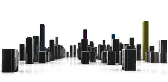
16 4. Thermography 101 Detection mechanism is the use of thermal imaging infrared cameras feature image or the target object and background radiation between different parts of the form to find and identify targets. Infrared detector output image is often referred to as "thermal imaging", because the same object or different objects in different parts of the infrared radiation reflection and their different strength. Using the difference between the object and the background radiation environment, and the difference of each portion of the radiation of the scene itself, can exhibit a thermal image of each part of the scenery radiation fluctuation, which can exhibit the characteristics of the scene. Thermal and visual images of the same object are different, it is not visible to the human eye to see the image, but the surface temperature distribution of the target image is the part will can be made to be visible from the camera sensor.

17 4. Thermography 101 Any object as long as its temperature above absolute zero ( ), although not light, infrared radiation, but can also be called infrared heat radiation. Objects of different temperatures in the infrared radiation is absorbed by the infrared detector, generating a temperature variation, resulting in electric effect, the electrical signal is amplified and then processed, the object is obtained with the surface of the heat distribution corresponding thermal image, that is, "thermal imaging." FPA. Image processing algorithms. Electronic processing circuit. Thermal imaging camera. Temperature measurement and calibration algorithms. Production, Adjustment process and Testing.
18 Chapter 2 Thermal imaging and visible imaging contrast

19 Thermal imaging and visible imaging contrast 1. Section contrast imaging 2. Performance Comparison 3. Effect of contrast
20 Thermal imaging and visible imaging contrast Compared, traditional cameras and thermal imaging cameras 1 contrast imaging modalities Ordinary camera (passive): by collecting the visible scene, thereby generating the image Infrared Camera (Active): With active infrared emission light emitting infrared light through the Central Plains and some light and capture the scene reflected infrared light back, thereby generating an image Thermal imaging cameras (passive): capture probe and the measured infrared radiation emitted by the scene, thereby generating the image
21 Thermal imaging and visible imaging contrast 1. Section contrast imaging 2. Performance Comparison 3. Effect of contrast

22 Thermal imaging and visible imaging contrast Ordinary camera Active infrared cameras Thermal imaging cameras Features Working conditions Passive Dependent on sunlight or lighting Active Dependence of infrared light Passive Is not light sensitive Monitoring distance Monitoring capabilities Hidden performance Temperature display Little monitoring range Monitoring role from the past Focuses on the resolution of the object Subtle performance in general, easier to expose strong light etc. Can not distinguish the target object temperature, influenced by the light Little monitoring range Monitoring role from the past Focuses on the resolution of the object Hidden poor performance, it is easy to expose weakness Can not distinguish the target object temperature, influenced by the light Large monitoring range Monitoring of the distance Focuses on the resolution of the object Good concealment, easy exposure Able to visualize the temperature difference between the surface of the object, without affecting light
23 Thermal imaging and visible imaging contrast 1. Section contrast imaging 2. Performance Comparison 3. Effect of contrast


24 Thermal imaging and visible imaging contrast Outdoor Close up: Ordinary camera Active infrared cameras Thermal imaging cameras


25 Thermal imaging and visible imaging contrast Indoor close view: Ordinary camera Active infrared cameras Thermal imaging cameras


26 Thermal imaging and visible imaging contrast External Wide field effect: Ordinary camera Active infrared cameras Thermal imaging cameras
27 Chapter 3 Thermal imaging Products
28 Thermal Imaging Products 1. Product composition & parameters 2. Product Features 3. Pros & cons of standard products


29 Thermal Imaging Products Thermal network cameras: The main component structure. Germanium metal lens H.264 coding standard Uncooled focal plane detector
 Support pseudo-color mode switching: Black hot / White Heat / Rainbow / on oxide red Support DVE image enhancement features Support Noise / mirroring Supports H.")
 card local storage, can effectively solve the video lost due to network failure caused the problem.")
30 Main Parameters Uncooled infrared focal plane sensor 8 ~ 14um long wave infrared detection pixels up to pixels Heat sensitivity, up to 50mK Support 8/15/25/35/50 mm focal length, such as fixed focus lens (optional) Support pseudo-color mode switching: Black hot / White Heat / Rainbow / on oxide red Support DVE image enhancement features Support Noise / mirroring Supports H.264 BP / MP / HP / MJPEG optional four coding algorithms and compatibility Real-time 3 yards stream output can meet local storage and network transmission of video 1 channel audio input, 1 channel audio output, two-way voice intercom Support Micro SD (maximum capacity to support 32GB) card local storage, can effectively solve the video lost due to network failure caused the problem. Hardware watchdog, fault auto recovery Metal linkage cooling design Three-axis rotation adjustable bracket for easy installation adjustment
31 Thermal Imaging Products 1. Product composition & parameters 2. Product Features 3. Pros & cons of standard products


32 1. Strong detection capability Characteristics of cameras Applicable under completely dark environment, we can clearly distinguish between different objects, identify camouflaged and concealed targets in the case of zero illumination


33 Characteristics of cameras Applicable to light, backlight, glare and other monitoring scenarios, without interference of light intensity can be achieved effective detection and identification in any scene light intensity.


34 Characteristics of cameras Application of smoke, fog, rain, snow, dust, glare obstructed view of the harsh environments. Suitable for high degree of color confusion, such as the scene camouflage, strong degree of difficulty a true all situation solution.

 60/110/180/250/350M Detection distance greater relationship with the")
35 Detection distance Characteristics of cameras Compared with ordinary camera, the thermal imaging cameras have longer detection range Fixed focus lens 8/15/25/35/50 mm (Lens Options at time of ordering) Focus Mode Manual FOV / / / / Aperture 1.0 Recognition distance (body) 60/110/180/250/350M Detection distance greater relationship with the weather


36 Characteristics of cameras Temperature identification function Thermal network cameras at different temperatures by detecting objects at different wavelengths emitted infrared heat radiation, the surface temperature of an object can be identified Cup filled with warm water (McCafé!) Electrical plug is being used
37 Thermal Imaging Products 1. Product composition & parameters 2. Product Features 3. Pros & cons of standard products
38 The Good, the Bad, the Ugly 1 Passive infrared, non-contact, good concealment. 2 All Weather monitoring, can pass through the smoke. Advantage 3 Role distance. 4 Temperature field can display objects. 5 Not affect the light. 1 Poor ability to distinguish details. Shortcoming 2 Transparent impermeable barrier such as glass. 3 Higher than typical camera cost.

39 Chapter 4 1. Showing the best of thermal.


40 Practical applications of thermal imaging cameras Warehouses, factories, prisons, parks and other perimeter Scene features: day night without light or no light, low resolution of complex scenes.


41 Practical applications of thermal imaging cameras Pipelines, electricity hub, border perimeter protection, etc. Scene Features: Monitor range, distance monitoring, for high detection capability.


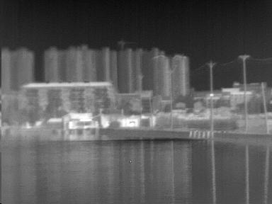
42 Practical applications of thermal imaging cameras Waterways, coastal, forest defense, port monitoring, surveillance and other airports Scene Features: Low visualization, security requirements monitoring difficult conditions


43 Practical applications of thermal imaging cameras Dessert, oil Fields, Mines, Chemical plants, etc. Scene features: air concentration differences, harsh weather conditions (snow and fog dust)


44 Practical applications of thermal imaging cameras Fire! Fire is often hidden from the obvious fire caused by existing traditional monitoring equipment, hard to find this hidden fire signs Thermal network cameras can quickly and efficiently find these hidden fire areas, and can accurately determine the location and extent of fire, timely control of the situation and eliminate hidden dangers and prevent the occurrence of a large area of fire.


45 Practical applications of thermal imaging cameras Application areas of search and rescue Thermal network cameras on the ability to identify precise temperatures, so that it can quickly and efficiently detect the temperature characteristics of different people in a complex scenario, in health care, life detection, search and rescue.
46 Practical applications of thermal imaging cameras Security, armed police investigation at night; prevent cross-border, drug trafficking and anti-terrorism. Night gives the best criminals and hiding place, according to statistics, 80% of criminal cases are at night. Fighting crime at night, the first to effectively find hidden suspects, criminals likely otherwise slip under the police's nose; If the front-line police officers equipped with advanced infrared night vision equipment, can greatly enhance deterrence against criminals, improve the efficiency of the fight against crime at night, reducing the casualty rate of police officers.


47 Practical applications of thermal imaging cameras Safe city living, aerial vantage. Thermal network cameras for aerial vantage points, can be used to control traffic around the clock to prevent fires, and for other emergencies services.


48 Practical applications of thermal imaging cameras Power line temperature measurement Integrated image, temperature and alarm analysis and other functions in one, substation temperature monitoring system software supporting the use of a composition of reliable performance infrared temperature monitoring system Automatic inspection Set the alarm Point, line, surface temperature dynamics Image

49 Thank You
Microbolometers for Infrared Imaging and the 2012 Student Infrared Imaging Competition
 Microbolometers for Infrared Imaging and the 2012 Student Infrared Imaging Competition George D Skidmore, PhD Principal Scientist DRS Technologies RSTA Group Competition Flyer 2 Passive Night Vision Technologies
Electromagnetic Waves
 Electromagnetic Waves What is an Electromagnetic Wave? An EM Wave is a disturbance that transfers energy through a field. A field is a area around an object where the object can apply a force on another
746A27 Remote Sensing and GIS
 746A27 Remote Sensing and GIS Lecture 1 Concepts of remote sensing and Basic principle of Photogrammetry Chandan Roy Guest Lecturer Department of Computer and Information Science Linköping University What
Geo/SAT 2 INTRODUCTION TO REMOTE SENSING
 Geo/SAT 2 INTRODUCTION TO REMOTE SENSING Paul R. Baumann, Professor Emeritus State University of New York College at Oneonta Oneonta, New York 13820 USA COPYRIGHT 2008 Paul R. Baumann Introduction Remote
Uses of Electromagnetic Waves
 Uses of Electromagnetic Waves 1 of 42 Boardworks Ltd 2016 Uses of Electromagnetic Waves 2 of 42 Boardworks Ltd 2016 What are radio waves? 3 of 42 Boardworks Ltd 2016 The broadcast of every radio and television
Where Image Quality Begins
 Where Image Quality Begins Filters are a Necessity Not an Accessory Inexpensive Insurance Policy for the System The most cost effective way to improve repeatability and stability in any machine vision
Chapter 16 Light Waves and Color
 Chapter 16 Light Waves and Color Lecture PowerPoint Copyright The McGraw-Hill Companies, Inc. Permission required for reproduction or display. What causes color? What causes reflection? What causes color?
Short Wave Infrared (SWIR) Imaging In Machine Vision
 Imaging In Machine Vision") Short Wave Infrared (SWIR) Imaging In Machine Vision Princeton Infrared Technologies, Inc. Martin H. Ettenberg, Ph. D. President martin.ettenberg@princetonirtech.com Ph: +01 609 917 3380 Booth Hall 1 J12
Short Wave Infrared (SWIR) Imaging In Machine Vision Princeton Infrared Technologies, Inc. Martin H. Ettenberg, Ph. D. President martin.ettenberg@princetonirtech.com Ph: +01 609 917 3380 Booth Hall 1 J12
SFR 406 Spring 2015 Lecture 7 Notes Film Types and Filters
 SFR 406 Spring 2015 Lecture 7 Notes Film Types and Filters 1. Film Resolution Introduction Resolution relates to the smallest size features that can be detected on the film. The resolving power is a related
Thermal Imaging Camera IR0001. Instruction Manual
 Thermal Imaging Camera IR0001 Instruction Manual Contents 1. Overview 2. Considerations and Safety Maintenance 3. Performance Index 2-3 4 5-6 4. Product features 7 5. Menu Description 8 6. Basic Operation
Lecture Notes Prepared by Prof. J. Francis Spring Remote Sensing Instruments
 Lecture Notes Prepared by Prof. J. Francis Spring 2005 Remote Sensing Instruments Material from Remote Sensing Instrumentation in Weather Satellites: Systems, Data, and Environmental Applications by Rao,
Conceptual Physics Fundamentals
 Conceptual Physics Fundamentals Chapter 13: LIGHT WAVES This lecture will help you understand: Electromagnetic Spectrum Transparent and Opaque Materials Color Why the Sky is Blue, Sunsets are Red, and
High Resolution 640 x um Pitch InSb Detector
 High Resolution 640 x 512 15um Pitch InSb Detector Chen-Sheng Huang, Bei-Rong Chang, Chien-Te Ku, Yau-Tang Gau, Ping-Kuo Weng* Materials & Electro-Optics Division National Chung Shang Institute of Science
LlIGHT REVIEW PART 2 DOWNLOAD, PRINT and submit for 100 points
 WRITE ON SCANTRON WITH NUMBER 2 PENCIL DO NOT WRITE ON THIS TEST LlIGHT REVIEW PART 2 DOWNLOAD, PRINT and submit for 100 points Multiple Choice Identify the choice that best completes the statement or
FOR 353: Air Photo Interpretation and Photogrammetry. Lecture 2. Electromagnetic Energy/Camera and Film characteristics
 FOR 353: Air Photo Interpretation and Photogrammetry Lecture 2 Electromagnetic Energy/Camera and Film characteristics Lecture Outline Electromagnetic Radiation Theory Digital vs. Analog (i.e. film ) Systems
746A27 Remote Sensing and GIS. Multi spectral, thermal and hyper spectral sensing and usage
 746A27 Remote Sensing and GIS Lecture 3 Multi spectral, thermal and hyper spectral sensing and usage Chandan Roy Guest Lecturer Department of Computer and Information Science Linköping University Multi
CHAPTER 7. Components of Optical Instruments
 CHAPTER 7 Components of Optical Instruments From: Principles of Instrumental Analysis, 6 th Edition, Holler, Skoog and Crouch. CMY 383 Dr Tim Laurens NB Optical in this case refers not only to the visible
Near-IR cameras... R&D and Industrial Applications
 R&D and Industrial Applications 1 Near-IR cameras... R&D and Industrial Applications José Bretes (FLIR Advanced Thermal Solutions) jose.bretes@flir.fr / +33 1 60 37 80 82 ABSTRACT. Human eye is sensitive
An Introduction to Remote Sensing & GIS. Introduction
 An Introduction to Remote Sensing & GIS Introduction Remote sensing is the measurement of object properties on Earth s surface using data acquired from aircraft and satellites. It attempts to measure something
Outline for today. Geography 411/611 Remote sensing: Principles and Applications. Remote sensing: RS for biogeochemical cycles
 Geography 411/611 Remote sensing: Principles and Applications Thomas Albright, Associate Professor Laboratory for Conservation Biogeography, Department of Geography & Program in Ecology, Evolution, & Conservation
Industrial Automation
 OPTICAL FIBER. SINGLEMODE OR MULTIMODE It is important to understand the differences between singlemode and multimode fiber optics before selecting one or the other at the start of a project. Its different
How can we "see" using the Infrared?
 The Infrared Infrared light lies between the visible and microwave portions of the electromagnetic spectrum. Infrared light has a range of wavelengths, just like visible light has wavelengths that range
IR Laser Illuminators
 Eagle Vision PAN/TILT THERMAL & COLOR CAMERAS - All Weather Rugged Housing resist high humidity and salt water. - Image overlay combines thermal and video image - The EV3000 CCD colour night vision camera
Lecture 2. Electromagnetic radiation principles. Units, image resolutions.
 NRMT 2270, Photogrammetry/Remote Sensing Lecture 2 Electromagnetic radiation principles. Units, image resolutions. Tomislav Sapic GIS Technologist Faculty of Natural Resources Management Lakehead University
Thermal Imaging Solutions Esprit Ti and TI2500
 Thermal Imaging Solutions Esprit Ti and TI2500 1 For all the power users who have been searching for a revolutionary advance in video system capabilities and performance, Pelco Thermal Imaging Solutions
Polaris Sensor Technologies, Inc. SMALLEST THERMAL POLARIMETER
 Polaris Sensor Technologies, Inc. SMALLEST THERMAL POLARIMETER Pyxis LWIR 640 Industry s smallest polarization enhanced thermal imager Up to 400% greater detail and contrast than standard thermal Real-time
Harmless screening of humans for the detection of concealed objects
 Safety and Security Engineering VI 215 Harmless screening of humans for the detection of concealed objects M. Kowalski, M. Kastek, M. Piszczek, M. Życzkowski & M. Szustakowski Military University of Technology,
Basic Function. Indoor environment
 ES288 Active IR Illuminator In the Night-vision Monitoring System, it is visible light the common illuminant for camera. But with the shortcoming of unhide, disturb the resident and easy exposure the monitor
High-performance MCT Sensors for Demanding Applications
 Access to the world s leading infrared imaging technology High-performance MCT Sensors for www.sofradir-ec.com High-performance MCT Sensors for Infrared Imaging White Paper Recent MCT Technology Enhancements
Chapter 8. Remote sensing
 1. Remote sensing 8.1 Introduction 8.2 Remote sensing 8.3 Resolution 8.4 Landsat 8.5 Geostationary satellites GOES 8.1 Introduction What is remote sensing? One can describe remote sensing in different
William Stallings Data and Computer Communications 7 th Edition. Chapter 4 Transmission Media
 William Stallings Data and Computer Communications 7 th Edition Chapter 4 Transmission Media Overview Guided - wire Unguided - wireless Characteristics and quality determined by medium and signal For guided,
Section 1 Wireless Transmission
 Part : Wireless Communication! section : Wireless Transmission! Section : Digital modulation! Section : Multiplexing/Medium Access Control (MAC) Section Wireless Transmission Intro. to Wireless Transmission
Unit 1.5 Waves. The number waves per second. 1 Hz is 1waves per second. If there are 40 waves in 10 seconds then the frequency is 4 Hz.
 Unit 1.5 Waves Basic information Transverse: The oscillations of the particles are at right angles (90 ) to the direction of travel (propagation) of the wave. Examples: All electromagnetic waves (Light,
Absentee layer. A layer of dielectric material, transparent in the transmission region of
 Glossary of Terms A Absentee layer. A layer of dielectric material, transparent in the transmission region of the filter, due to a phase thickness of 180. Absorption curve, absorption spectrum. The relative
Int n r t o r d o u d c u ti t on o n to t o Remote Sensing
 Introduction to Remote Sensing Definition of Remote Sensing Remote sensing refers to the activities of recording/observing/perceiving(sensing)objects or events at far away (remote) places. In remote sensing,
Radar. Seminar report. Submitted in partial fulfillment of the requirement for the award of degree Of Mechanical
 A Seminar report on Radar Submitted in partial fulfillment of the requirement for the award of degree Of Mechanical SUBMITTED TO: SUBMITTED BY: www.studymafia.org www.studymafia.org Preface I have made
Section Electromagnetic Waves and the Electromagnetic Spectrum
 Section 17.6 Electromagnetic Waves and the Electromagnetic Spectrum Electromagnetic Waves Can you name all the colors of the rainbow? Red, Orange, Yellow, Green, Blue, Indigo, Violet Electromagnetic Waves
Computer Networks Lecture -4- Transmission Media. Dr. Methaq Talib
 Computer Networks Lecture -4- Transmission Media Dr. Methaq Talib Transmission Media A transmission medium can be broadly defined as anything that can carry information from a source to a destination.
1.6 Beam Wander vs. Image Jitter
 8 Chapter 1 1.6 Beam Wander vs. Image Jitter It is common at this point to look at beam wander and image jitter and ask what differentiates them. Consider a cooperative optical communication system that
Innovative optical solutions. Inspector M2 Manual
 Innovative optical solutions Inspector M2 Manual DANGER Ultraviolet radiation emitted from this product. Avoid exposure. Never look directly into the lamp. Exposure can cause eye and skin allergy and allergic
PRODUCT OVERVIEW FOR THE. Corona 350 II FLIR SYSTEMS POLYTECH AB
 PRODUCT OVERVIEW FOR THE Corona 350 II FLIR SYSTEMS POLYTECH AB Table of Contents Table of Contents... 1 Introduction... 2 Overview... 2 Purpose... 2 Airborne Data Acquisition and Management Software (ADAMS)...
Polaris Sensor Technologies, Inc. Visible - Limited Detection Thermal - No Detection Polarization - Robust Detection etherm - Ultimate Detection
 Polaris Sensor Technologies, Inc. DETECTION OF OIL AND DIESEL ON WATER Visible - Limited Detection - No Detection - Robust Detection etherm - Ultimate Detection Pyxis Features: Day or night real-time sensing
Continuous Wave Laser Illumination: The Clear Choice over Thermal Imaging for Long-Range, High-Magnification Night Vision Perimeter Protection
 Continuous Wave Laser Illumination: The Clear Choice over Thermal Imaging for Long-Range, High- September 2008 Contents Executive Summary...3 Thermal Imaging and Continuous Wave Laser Illumination Defined...3
Electromagnetic Spectrum
 Electromagnetic Spectrum Wave - Review Waves are oscillations that transport energy. 2 Types of waves: Mechanical waves that require a medium to travel through (sound, water, earthquakes) Electromagnetic
COLOUR INSPECTION, INFRARED AND UV
 COLOUR INSPECTION, INFRARED AND UV TIPS, SPECIAL FEATURES, REQUIREMENTS LARS FERMUM, CHIEF INSTRUCTOR, STEMMER IMAGING THE PROPERTIES OF LIGHT Light is characterized by specifying the wavelength, amplitude
PROJECT REPORT COUPLING OF LIGHT THROUGH FIBER PHY 564 SUBMITTED BY: GAGANDEEP KAUR ( )
") PROJECT REPORT COUPLING OF LIGHT THROUGH FIBER PHY 564 SUBMITTED BY: GAGANDEEP KAUR (952549116) 1 INTRODUCTION: An optical fiber (or fiber) is a glass or plastic fiber that carries light along its length.
PROJECT REPORT COUPLING OF LIGHT THROUGH FIBER PHY 564 SUBMITTED BY: GAGANDEEP KAUR (952549116) 1 INTRODUCTION: An optical fiber (or fiber) is a glass or plastic fiber that carries light along its length.
Tunable wideband infrared detector array for global space awareness
 Tunable wideband infrared detector array for global space awareness Jonathan R. Andrews 1, Sergio R. Restaino 1, Scott W. Teare 2, Sanjay Krishna 3, Mike Lenz 3, J.S. Brown 3, S.J. Lee 3, Christopher C.
polarized collection version 17.1
 polarized collection version 17.1 why settle when you can go? It didn t take long for Edge Eyewear to recognize a need for polarized technology in the safety eyewear industry. In 1999, we became the 1st
Understanding Infrared Camera Thermal Image Quality
 Access to the world s leading infrared imaging technology Noise { Clean Signal www.sofradir-ec.com Understanding Infared Camera Infrared Inspection White Paper Abstract You ve no doubt purchased a digital
Light waves. VCE Physics.com. Light waves - 2
 Light waves What is light? The electromagnetic spectrum Waves Wave equations Light as electromagnetic radiation Polarisation Colour Colour addition Colour subtraction Interference & structural colour Light
General Imaging System
 General Imaging System Lecture Slides ME 4060 Machine Vision and Vision-based Control Chapter 5 Image Sensing and Acquisition By Dr. Debao Zhou 1 2 Light, Color, and Electromagnetic Spectrum Penetrate
MR-i. Hyperspectral Imaging FT-Spectroradiometers Radiometric Accuracy for Infrared Signature Measurements
 MR-i Hyperspectral Imaging FT-Spectroradiometers Radiometric Accuracy for Infrared Signature Measurements FT-IR Spectroradiometry Applications Spectroradiometry applications From scientific research to
Enhanced LWIR NUC Using an Uncooled Microbolometer Camera
 Enhanced LWIR NUC Using an Uncooled Microbolometer Camera Joe LaVeigne a, Greg Franks a, Kevin Sparkman a, Marcus Prewarski a, Brian Nehring a a Santa Barbara Infrared, Inc., 30 S. Calle Cesar Chavez,
17-1 Electromagnetic Waves
 17-1 Electromagnetic Waves transfers energy called electromagnetic radiation no medium needed transverse some electrical, some magnetic properties speed is 300,000,000 m/s; nothing is faster; at this speed
MR-i. Hyperspectral Imaging FT-Spectroradiometers Radiometric Accuracy for Infrared Signature Measurements
 MR-i Hyperspectral Imaging FT-Spectroradiometers Radiometric Accuracy for Infrared Signature Measurements FT-IR Spectroradiometry Applications Spectroradiometry applications From scientific research to
Part 1. Introductory examples. But first: A movie! Contents
 Contents TSBB09 Image Sensors Infrared and Multispectral Sensors Jörgen Ahlberg 2015-11-13 1. Introductory examples 2. Infrared, and other, light 3. Infrared cameras 4. Multispectral cameras 5. Application
Sensing. Autonomous systems. Properties. Classification. Key requirement of autonomous systems. An AS should be connected to the outside world.
 Sensing Key requirement of autonomous systems. An AS should be connected to the outside world. Autonomous systems Convert a physical value to an electrical value. From temperature, humidity, light, to
remote sensing? What are the remote sensing principles behind these Definition
 Introduction to remote sensing: Content (1/2) Definition: photogrammetry and remote sensing (PRS) Radiation sources: solar radiation (passive optical RS) earth emission (passive microwave or thermal infrared
Introduction to Remote Sensing Fundamentals of Satellite Remote Sensing. Mads Olander Rasmussen
 Introduction to Remote Sensing Fundamentals of Satellite Remote Sensing Mads Olander Rasmussen (mora@dhi-gras.com) 01. Introduction to Remote Sensing DHI What is remote sensing? the art, science, and technology
Reading 28 PROPAGATION THE IONOSPHERE
 Reading 28 Ron Bertrand VK2DQ http://www.radioelectronicschool.com PROPAGATION THE IONOSPHERE The ionosphere is a region of the upper atmosphere extending from a height of about 60 km to greater than 500
FLASH LiDAR KEY BENEFITS
 In 2013, 1.2 million people died in vehicle accidents. That is one death every 25 seconds. Some of these lives could have been saved with vehicles that have a better understanding of the world around them
Thermography. White Paper: Understanding Infrared Camera Thermal Image Quality
 Electrophysics Resource Center: White Paper: Understanding Infrared Camera 373E Route 46, Fairfield, NJ 07004 Phone: 973-882-0211 Fax: 973-882-0997 www.electrophysics.com Understanding Infared Camera Electrophysics
ELECTROMAGNETIC WAVES AND THE EM SPECTRUM MR. BANKS 8 TH GRADE SCIENCE
 ELECTROMAGNETIC WAVES AND THE EM SPECTRUM MR. BANKS 8 TH GRADE SCIENCE ELECTROMAGNETIC WAVES Do not need matter to transfer energy. Made by vibrating electric charges. When an electric charge vibrates,
Compact Dual Field-of-View Telescope for Small Satellite Payloads
 Compact Dual Field-of-View Telescope for Small Satellite Payloads James C. Peterson Space Dynamics Laboratory 1695 North Research Park Way, North Logan, UT 84341; 435-797-4624 Jim.Peterson@sdl.usu.edu
LightPath. Infrared Optics. Leaders in aspheric optics and assemblies TECHNOLOGIES
 LightPath TECHNOLOGIES Infrared Optics Leaders in aspheric optics and assemblies Infrared Optics from the Experts in Molded Glass Optics Leaders in chalcogenide glass Molding Enhanced thermal performance
LWIR NUC Using an Uncooled Microbolometer Camera
 LWIR NUC Using an Uncooled Microbolometer Camera Joe LaVeigne a, Greg Franks a, Kevin Sparkman a, Marcus Prewarski a, Brian Nehring a, Steve McHugh a a Santa Barbara Infrared, Inc., 30 S. Calle Cesar Chavez,
Human Retina. Sharp Spot: Fovea Blind Spot: Optic Nerve
 I am Watching YOU!! Human Retina Sharp Spot: Fovea Blind Spot: Optic Nerve Human Vision Optical Antennae: Rods & Cones Rods: Intensity Cones: Color Energy of Light 6 10 ev 10 ev 4 1 2eV 40eV KeV MeV Energy
Classical Optical Solutions
 Petzval Lens Enter Petzval, a Hungarian mathematician. To pursue a prize being offered for the development of a wide-field fast lens system he enlisted Hungarian army members seeing a distraction from
Applications of Optics
 Nicholas J. Giordano www.cengage.com/physics/giordano Chapter 26 Applications of Optics Marilyn Akins, PhD Broome Community College Applications of Optics Many devices are based on the principles of optics
Test 1: Example #2. Paul Avery PHY 3400 Feb. 15, Note: * indicates the correct answer.
 Test 1: Example #2 Paul Avery PHY 3400 Feb. 15, 1999 Note: * indicates the correct answer. 1. A red shirt illuminated with yellow light will appear (a) orange (b) green (c) blue (d) yellow * (e) red 2.
ULISSE COMPACT THERMAL
 2014/01/20 UNIT WITH INTEGRATED THERMAL AND DAY/NIGHT CAMERAS MAIN FEATURES Variable speed: 0.1-200 /s Pan/Tilt Horizontal continuous rotation, vertical -90 /+90 IP66 Dual independent video output Complete
INFRARED IMAGING-PASSIVE THERMAL COMPENSATION VIA A SIMPLE PHASE MASK
 Romanian Reports in Physics, Vol. 65, No. 3, P. 700 710, 2013 Dedicated to Professor Valentin I. Vlad s 70 th Anniversary INFRARED IMAGING-PASSIVE THERMAL COMPENSATION VIA A SIMPLE PHASE MASK SHAY ELMALEM
Material analysis by infrared mapping: A case study using a multilayer
 Material analysis by infrared mapping: A case study using a multilayer paint sample Application Note Author Dr. Jonah Kirkwood, Dr. John Wilson and Dr. Mustafa Kansiz Agilent Technologies, Inc. Introduction
Improving the Collection Efficiency of Raman Scattering
 PERFORMANCE Unparalleled signal-to-noise ratio with diffraction-limited spectral and imaging resolution Deep-cooled CCD with excelon sensor technology Aberration-free optical design for uniform high resolution
Advances in slabs defects inspection with Conoscopic Holography. Ignacio Alvarez, J.M. Enguita (UniOvi) J. Marina, R.
 J. Marina, R.") Advances in slabs defects inspection with Conoscopic Holography Ignacio Alvarez, J.M. Enguita (UniOvi) J. Marina, R. García (DSIplus) Advances in slabs defects inspection with C.H. Contents: Surface inspection
Advances in slabs defects inspection with Conoscopic Holography Ignacio Alvarez, J.M. Enguita (UniOvi) J. Marina, R. García (DSIplus) Advances in slabs defects inspection with C.H. Contents: Surface inspection
2. The Basic principle of optical fibre (Or) Working principle of optical fibre (or) Total internal reflection
 Working principle of optical fibre (or) Total internal reflection") Introduction Fibre optics deals with the light propagation through thin glass fibres. Fibre optics plays an important role in the field of communication to transmit voice, television and digital data signals
Introduction Fibre optics deals with the light propagation through thin glass fibres. Fibre optics plays an important role in the field of communication to transmit voice, television and digital data signals
Comparison of passive millimeter-wave and IR imagery in a nautical environment
 Comparison of passive millimeter-wave and IR imagery in a nautical environment Appleby, R., & Coward, P. (2009). Comparison of passive millimeter-wave and IR imagery in a nautical environment. 1-8. Paper
Lithography. 3 rd. lecture: introduction. Prof. Yosi Shacham-Diamand. Fall 2004
 Lithography 3 rd lecture: introduction Prof. Yosi Shacham-Diamand Fall 2004 1 List of content Fundamental principles Characteristics parameters Exposure systems 2 Fundamental principles Aerial Image Exposure
Application Note. Digital Low-Light CMOS Camera. NOCTURN Camera: Optimized for Long-Range Observation in Low Light Conditions
 Digital Low-Light CMOS Camera Application Note NOCTURN Camera: Optimized for Long-Range Observation in Low Light Conditions PHOTONIS Digital Imaging, LLC. 6170 Research Road Suite 208 Frisco, TX USA 75033
Absorption: in an OF, the loss of Optical power, resulting from conversion of that power into heat.
 Absorption: in an OF, the loss of Optical power, resulting from conversion of that power into heat. Scattering: The changes in direction of light confined within an OF, occurring due to imperfection in
Application Note. Tactical Applications of Thermal Imaging in a Maritime Environment
 Application Note Tactical Applications of Thermal Imaging in a Maritime Environment Tactical Applications of Thermal Imaging in a Maritime Environment Introduction Missions for public safety boats are
Mod. 2 p. 1. Prof. Dr. Christoph Kleinn Institut für Waldinventur und Waldwachstum Arbeitsbereich Fernerkundung und Waldinventur
 Histograms of gray values for TM bands 1-7 for the example image - Band 4 and 5 show more differentiation than the others (contrast=the ratio of brightest to darkest areas of a landscape). - Judging from
SER: Biological Stains Visualization with Alternate Light Sources
 Sources Safety SAFETY WARNING! Do not look directly into the beam. Safety glasses with the proper viewing filters must always be worn to protect the eyes from the intense light emitted by a forensic light
Measuring intensity in watts rather than lumens
 Specialist Article Appeared in: Markt & Technik Issue: 43 / 2013 Measuring intensity in watts rather than lumens Authors: David Schreiber, Developer Lighting and Claudius Piske, Development Engineer Hardware
Technical Notes. Introduction. Optical Properties. Issue 6 July Figure 1. Specular Reflection:
 Technical Notes This Technical Note introduces basic concepts in optical design for low power off-grid lighting products and suggests ways to improve optical efficiency. It is intended for manufacturers,
Chapters 1-3. Chapter 1: Introduction and applications of photogrammetry Chapter 2: Electro-magnetic radiation. Chapter 3: Basic optics
 Chapters 1-3 Chapter 1: Introduction and applications of photogrammetry Chapter 2: Electro-magnetic radiation Radiation sources Classification of remote sensing systems (passive & active) Electromagnetic
Chapter 9: Light, Colour and Radiant Energy. Passed a beam of white light through a prism.
 Chapter 9: Light, Colour and Radiant Energy Where is the colour in sunlight? In the 17 th century (1600 s), Sir Isaac Newton conducted a famous experiment. Passed a beam of white light through a prism.
Match the correct description with the correct term. Write the letter in the space provided.
 Skills Worksheet Directed Reading A Section: Interactions of Light with Matter REFLECTION Write the letter of the correct answer in the space provided. 1. What happens when light travels through a material
Low Cost Earth Sensor based on Oxygen Airglow
 Assessment Executive Summary Date : 16.06.2008 Page: 1 of 7 Low Cost Earth Sensor based on Oxygen Airglow Executive Summary Prepared by: H. Shea EPFL LMTS herbert.shea@epfl.ch EPFL Lausanne Switzerland
New Technologies that Resolve Common Challenges Facing IP Surveillance. By: David Heath Axis Communications
 New Technologies that Resolve Common Challenges Facing IP Surveillance By: David Heath Axis Communications Agenda Difficult lighting conditions Low Light/No light Back Lighting High Band-Width requirements
Plasma in the ionosphere Ionization and Recombination
 Plasma in the ionosphere Ionization and Recombination Jamil Muhammad Supervisor: Professor kjell Rönnmark 1 Contents: 1. Introduction 3 1.1 History.3 1.2 What is the ionosphere?...4 2. Ionization and recombination.5
Full Spectrum. Full Calibration. Full Testing. Collimated Optics, Software and Uniform Source Solutions
 Full Spectrum. Full Calibration. Full Testing. Collimated Optics, Software and Uniform Source Solutions Combining the Expertise of Two Industry Leaders to Give You An Immense Range of Complete Electro-Optical
Note 2 Electromagnetic waves N2/EMWAVES/PHY/XII/CHS2012
 ELECTROMAGNETIC SPECTRUM Electromagnetic waves include visible light waves, X-rays, gamma rays, radio waves, microwaves, ultraviolet and infrared waves. The classification of em waves according to frequency
Alternate Light Source Imaging
 Alternate Light Source Imaging This page intentionally left blank Alternate Light Source Imaging Forensic Photography Techniques Norman Marin Jeffrey Buszka Series Editor Larry S. Miller First published
Photonics and Optical Communication
 Photonics and Optical Communication (Course Number 300352) Spring 2007 Dr. Dietmar Knipp Assistant Professor of Electrical Engineering http://www.faculty.iu-bremen.de/dknipp/ 1 Photonics and Optical Communication
Thomas G. Cleary Building and Fire Research Laboratory National Institute of Standards and Technology Gaithersburg, MD U.S.A.
 Thomas G. Cleary Building and Fire Research Laboratory National Institute of Standards and Technology Gaithersburg, MD 20899 U.S.A. Video Detection and Monitoring of Smoke Conditions Abstract Initial tests
On the use of water color missions for lakes in 2021
 Lakes and Climate: The Role of Remote Sensing June 01-02, 2017 On the use of water color missions for lakes in 2021 Cédric G. Fichot Department of Earth and Environment 1 Overview 1. Past and still-ongoing
5 FACTORS INFLUENCING RADIOMETRIC TEMPERATURE MEASUREMENTS
 5 FACTORS INFLUENCING RADIOMETRIC TEMPERATURE MEASUREMENTS CONTENTS Page Introduction 2 1. Radiometry and Surface Characteristics 3 2. Emissivity 4 3. Reflectivity 5 4. Effects of Atmosphere 6 5. Resolution
A bluffer s guide to Radar
 A bluffer s guide to Radar Andy French December 2009 We may produce at will, from a sending station, an electrical effect in any particular region of the globe; (with which) we may determine the relative
Camera Setup and Field Recommendations
 Camera Setup and Field Recommendations Disclaimers and Legal Information Copyright 2011 Aimetis Inc. All rights reserved. This guide is for informational purposes only. AIMETIS MAKES NO WARRANTIES, EXPRESS,