Model: HF100-Eagle USER S MANUAL
|
|
|
- Gabriel Dalton
- 6 years ago
- Views:
Transcription


1 Model: HF100-Eagle USER S MANUAL
2 THIS PAGE WAS INTENTIONALLY LEFT BLANK 1
3 TABLE OF CONTENTS 1. INTRODUCTION SYMBOLS WARNINGS AND PRECAUTIONS WARNINGS AND/OR CAUTION DURING TRANSPORTATION AND STORAGE TRANSPORTATION OR STORAGE ENVIRONMENTAL CONDITIONS INSTALLED EQUIPMENT CONDITIONS BETWEEN OPERATIONS OPERATIONAL ENVIRONMENTAL CONDITIONS ADDITIONAL PROCEDURES PRIOR TO EQUIPMENT USE WARNINGS AND/OR CAUTION TO BE ADOPTED WARNINGS AND/OR CAUTION DURING EQUIPMENT INSTALLATION WARNING AND/OR CAUTION DURING EQUIPMENT USE WARNING AND/OR CAUTION AFTER EQUIPMENT USE/OPERATION CAUTION IN CASE OF ABNORMAL EQUIPMENT FUNCTION ENCOMPASS PANORAMIC X-RAY SYSTEM OVERVIEW DIGITAL SNAP-ON CONFIGURATION DIGITAL FIXED CONFIGURATION FILM CONFIGURATION FREE STANDING BASE (OPTIONAL) COMPUTER SYSTEM REQUIREMENTS NETWORK ADAPTER CONFIGURATION INSTALLING THE IMAGING SOFTWARE IMAGING PROGRAMS PANORAMIC PROFILES: CEPHALOMETRIC PROFILES: CONTROL PANEL INTRODUCTION CONTROL PANEL KEYS CONTROL PANEL INDICATING LIGHTS REMOTE EXPOSURE SWITCH (OPTIONAL) TURNING THE EQUIPMENT ON MAIN SCREEN PREPARING FOR THE EXPOSURE
4 10.1. INSERTING/REMOVING THE SNAP-ON SENSOR FOR PANORAMIC OR CEPHALOMETRIC POSITION INSERTING THE FILM IN THE PANORAMIC FILM HOLDER INSERTING/REMOVING THE FILM IN CEPHALOMETIC POSITION BEFORE POSITIONING THE PATIENT GETTING THE SOFTWARE READY (FOR DIGITAL VERSION) PANORAMIC EXPOSURES GETTING THE SOFTWARE READY (DIGITAL VERSION ONLY) POSITIONING THE PATIENT TAKING A PANORAMIC EXPOSURE CEPHALOMETRIC EXPOSURE GETTING THE SOFTWARE READY (DIGITAL VERSION ONLY) POSITIONING THE PATIENT TAKING A CEPHALOMETRIC EXPOSURE PROCEDURES FOR REUSE CLEANING DISINFECTION TROUBLESHOOTING GUIDE UNIT OPERATION PROBLEM IMAGE QUALITY PROBLEM PATIENT POSITIONING PROBLEM DISPOSAL OF THE UNIT ENVIRONMENTAL CONTAMINATION EQUIPMENT INSTALLATION, CORRECTIVE MAINTENANCE AND CALIBRATION INSTALLATION OF THE EQUIPMENT CORRECTIVE MAINTENANCE PREVENTIVE MAINTENANCE CALIBRATION NETWORK OF AUTHORIZED SERVICE TECHNICIANS TECHNICAL SPECIFICATIONS REGULATORY INFORMATION GENERAL INFORMATION RADIOLOGICAL INFORMATION X-RAY GENERATOR TESTED EQUIPMENT LAW NORM IRRADIATED FIELD SIZE - ANALOG AND DIGITAL PANORAMIC EXAM (PAN: ADULT AND CHILD TMJ MAXILLARY SINUS) IRRADIATED FIELD SIZE DIGITAL CEPH EXAM: IRRADIATED FIELD SIZE ANALOG CEPH EXAM (LATERAL AND LATERAL SIDE 45º)
5 17.9. IRRADIATED FIELD SIZE ANALOG CEPH EXAM (POSTERIOR AND ANTERIOR) TUBE SPECIFICATIONS COOLING TIME BY TECHNIQUE USED ELECTROMAGNETIC EMISSIONS ELECTROMAGNETIC IMMUNITY CHARACTERISTIC COOLING OF THE X-RAY GENERATOR CHARACTERISTIC CURVES OF THE X-RAY TUBE LABELS OF IDENTIFICATION EQUIPMENT DIMENSIONS SERIAL NUMBER OF THE X-RAY TUBE
6 Attention For greater safety: Read and understand all instructions written in this manual before installation or use of the equipment. This instruction manual should be read by all operators of the equipment. This instruction manual was originally written in Portuguese. Intended Use Intended for dental radiographic examination and diagnosis of diseases of the teeth, jaw and oral structures. CAUTION US FEDERAL LAW RESTRICTS THIS DEVICE TO SALE BY OR ON THE ORDER OF A DENTIST OR PHYSICIAN. Warning Statement Only personnel authorized by Panoramic Corporation are qualified to install and service this equipment. Any attempt to install or service this equipment by anyone not so authorized will void the warranty. It is imperative that this equipment be installed, serviced, and used by personnel familiar with the precautions required to prevent excessive exposure to both primary and secondary radiation. This equipment features protective designs for limiting both the primary and secondary radiation produced by the X-ray beam. However, design features cannot prevent carelessness, negligence, or lack of knowledge. Panoramic Corporation requires anyone moving or transporting their machine to contact the Service Department at (800)
7 1. INTRODUCTION The ENCOMPASS Panoramic X-Ray Machine is a complete system for dental imaging capable of: Film Panoramic Profiles Film Cephalometric Profiles Digital Panoramic Profiles Digital Cephalometric Profiles The digital machines use a sensor with CdTe/CMOS technology for imaging that allows for direct conversion between x-ray photons into voltage levels, making it less noisy than traditional scintillator technologies. The equipment has three movement axes (two in orthogonal directions and one rotational) making it possible to execute elaborate imaging profiles. It features a complex profile movement around the dental arch and radiographic emission compensation in the spinal region, when necessary reconstructing the dental arch into a plane image. Each individual profile prioritizes a set of characteristics improving diagnostic capabilities. For example, the standard panoramic prioritizes image layer width, constant vertical magnification and homogeneous exposure along the whole image. Likewise, the low dosage profile prioritizes the reduction of dosage (time and anodic current). The profiles can be applied to a variety of patients: adult or child; small, medium or large. The equipment has predefined exposure parameters depending on patient type. However, the user can apply whatever is best for the situation. The user interface is composed of a control panel located close to the patient chin rest and an exposure switch. A remote exposure switch installed outside the radiation room is optional. The exposure switch is a dead-man type switch. Ease of patient positioning is complimented by the patient entry into the machine from the side. There are three lasers available for positioning: Mid-Saggital plane, Frankfurt Plane and Image Layer Plane (canine). These features make it possible for the user to precisely position the patient. For patient comfort, a demonstration mode is also available making it possible to inform the patient of the procedure prior to exposure. 6

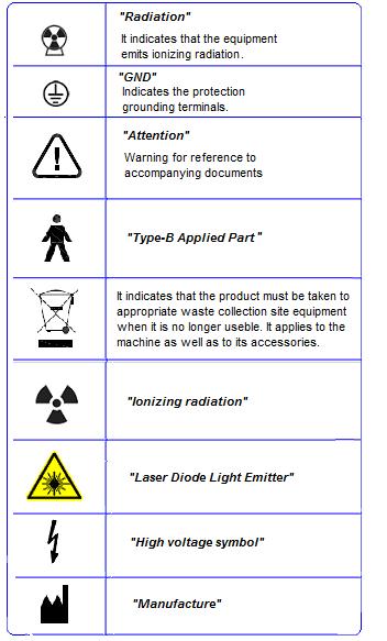
8 2. SYMBOLS Use the icons below to identify the symbols on your equipment. 7
9 8
10 3. WARNINGS AND PRECAUTIONS 3.1. WARNINGS AND/OR CAUTION DURING TRANSPORTATION AND STORAGE The equipment must be transported and stored by observing the following: Care should be taken to prevent falls and impact. The arrows must be pointing upwards. Do not stack. Protect against moisture, rainwater aspersion and wet ground. This equipment must be unpacked and installed by an authorized technician. Premature unpacking does not generate safety risks, but leads to the equipment warranty voidance TRANSPORTATION OR STORAGE ENVIRONMENTAL CONDITIONS Environmental temperature range for transportation and storage 0ºC to +55ºC (+32 F to 131 F) 3.3. INSTALLED EQUIPMENT CONDITIONS BETWEEN OPERATIONS Storage ambient temperature range Ambient temperature range recommended by manufacturer Storage relative humidity range Atmospheric pressure range +5 C to +45 C (+41 F to 113 F) +15 C a +30 C (+59 F to 86 F) 30% to 75% (noncondensing) 700 hpa to 1060 hpa (525 mmhg to 795 mmhg) 3.4. OPERATIONAL ENVIRONMENTAL CONDITIONS 9
11 Operation ambient temperature range +10 C to +35 C (+50 F to 95 F) Ambient temperature range recommended +21 C a +26 C (69.8 F to 78.8 F) Operation relative humidity range 30% to 75% (non condensing) Atmospheric pressure range 700 hpa to 1060 hpa (525 mmhg to 795 mmhg) 3.5. ADDITIONAL PROCEDURES PRIOR TO EQUIPMENT USE Even prior to its first use, the equipment must be cleaned and disinfected; the same additional procedures must be followed for reuse, as described in chapter WARNINGS AND/OR CAUTION TO BE ADOPTED WARNINGS AND/OR CAUTION DURING EQUIPMENT INSTALLATION The equipment must be installed only by service technicians authorized by the manufacturer. Place the equipment on a site where it will not be in contact with moisture or water. Install the unit on a site where it will not be damaged by pressure, temperature, moisture, direct sunlight, dust or salts. The equipment must not be submitted to inclination, excessive vibration or shock (including during transportation and handling). This equipment has not been designed for use in facilities where vapors, flammable anesthetic mixtures in contact with air, oxygen or nitrous oxide can be detected. Check the equipment s voltage when performing electric installation. Failure to do so may damage the equipment. The equipment must be properly grounded. Failure to do so may result in Safety Hazard. Depending on local regulation the X-Ray emission control may require installation outside the facility where the equipment is placed, and the operator may need visual contact with the patient through a window with radiological glass or similar, since the operator must not lose visual contact with the patient. Mobile and portable RF communication equipment can affect the ENCOMPASS Panoramic X-Ray Machine. This equipment must be solely used by health care professionals as it may cause radio interference or interrupt the operation of nearby equipment. Mitigatory measures, such as equipment re-orientation or replacement and the facility s screening, may be necessary WARNING AND/OR CAUTION DURING EQUIPMENT USE 10
12 The equipment must be operated only by qualified and trained professionals (dentists, radiology technicians, hygienists or engineers). Always observe the display messages, the equipment as a whole and the patient in order to detect any arising problems early. In case occasional maintenance is required, use only services provided by Authorized Service Technicians. The equipment has been designed to withstand continual and intermittent operation; therefore, follow the cycles described in these operation instructions. Since radiation exposure can cause damage to human cells, it is recommended that no one should remain in the radiographic examination room, unless the patient requires restraint. In this case, such individual must be properly protected against X-Ray emission. Although this equipment has been designed according to electromagnetic compatibility standards, it may, under very extreme conditions, interfere with other equipment. Do not use it with other devices that are sensitive to interference or with devices that create high electromagnetic disturbances. THE MANUFACTURER SHALL NOT BE LIABLE IN CASE: ATTENTION THE X-RAY MACHINE IS USED FOR PURPOSES OTHER THAN THOSE FOR WHICH IT HAS BEEN DESIGNED. DAMAGE CAUSED TO THE EQUIPMENT, THE OPERATOR AND/OR PATIENT AS A RESULT OF IMPROPER INSTALLATION AND MAINTENANCE PROCEDURES IN DISAGREEMENT WITH THE OPERATION INSTRUCTIONS ACCOMPANYING THE EQUIPMENT. IMPROPER EQUIPMENT OPERATION WARNING AND/OR CAUTION AFTER EQUIPMENT USE/OPERATION Turn off the x-ray machine's master switch when it is not used for long periods of time. Always keep the equipment clean for its next operation. If the equipment is defective, do not try to fix it yourself, instead call for authorized technical assistance. Do not replace any equipment parts. Do not disconnect the cable or other connections unnecessarily. The ENCOMPASS Panoramic X-Ray Machine must be off when other equipment such as an electric scalpel or other similar devices are being used. After using the equipment, clean and disinfect all parts that may have been in contact with the patient. 11
13 3.7. CAUTION IN CASE OF ABNORMAL EQUIPMENT FUNCTION In case the equipment shows abnormal heating, noise or any other type of abnormality, check if the problem is related to any of the items listed in chapter 12. If the problem cannot be solved, turn off the equipment and call for Authorized Technical Assistance. Use the website or call the Panoramic Service Department at 1 (800)


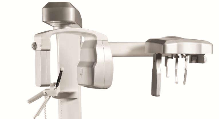
14 4. ENCOMPASS PANORAMIC X-RAY SYSTEM OVERVIEW 4.1. DIGITAL SNAP-ON CONFIGURATION The following image shows the whole system with optional Ceph arm mounted. Moving Mechanism Head Support Cephalostat Arm Cephalostat (Optional) Rotating Arm SNAP-ON Sensor Control Panel Ear Rods SNAP-ON Sensor Holder Patient Handles Exposure Button X-Ray Tube Head Patient Support Nose Support Secondary Collimator Column On / Off Switch Base (optional) 13

15 4.2. DIGITAL FIXED CONFIGURATION The following image shows the whole system. No optional ceph arm is available in this configuration. Moving Mechanism Rotating Arm Digital Sensor X-Ray Tube Head Control Panel Patient Handles Column Patient Support Head Support Base 4.3. FILM CONFIGURATION 14
 Panoramic Film Holder Ear Rods Cephalometric Film Holder Control Panel Patient Handles Head Support")
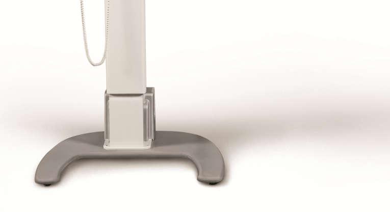
16 The following image shows the whole system with optional Ceph arm mounted. Rotating Arm Moving Mechanism X-Ray Tube Head Cephalostat Arm Cephalostat Film Holder (Optional) Panoramic Film Holder Ear Rods Cephalometric Film Holder Control Panel Patient Handles Head Support Patient Support Column Base 4.4. FREE STANDING BASE (OPTIONAL) The following image shows the optional Free Standing Base. 15

17 The equipment will be fixed to the base and wall by an authorized technician during installation. 16
18 5. COMPUTER SYSTEM REQUIREMENTS It is imperative that this computer system have an EXCLUSIVE USE for EAGLE Panoramic X-Ray Machine. This system MUST fulfill the following requirements. Table 1 - Computer Requirements Operating System Windows XP professional SP3; Windows Vista Business; Windows 7 professional (32 bit) CPU Intel Core 2 Due 3.0 Ghz ou higher HDD 10 GB of free disk space RAM 4GB DDR2 SDRAM PCI PCI Express (PCIe) slot, full-height NIC Gigabit Ethernet dedicated (32 bit) ATENTION THE NETWORK ADAPTER IS SHIPPED WITH THE EQUIPMENT. THE HARDWARE MUST BE INSTALLED BY A TECHNICIAN AUTHORIZED BY THE COMPUTER MANUFACTURER, OTHERWISE MAY RESULT IN THE EVENT BEING DEEMED OUT OF WARRANTY 6. NETWORK ADAPTER CONFIGURATION To verify installation of the network card, follow the procedure: 1 Verify the Windows system automatically installed the driver for the capture card. Control Panel All items Control Panel System Device Manager Network Adapters 17

19 2 - Make sure the network adapter is installed. If not, install the network card drive using the CD shipped with the equipment. 3 - After installation restart the computer. To configure the network card, follow the procedure: 1 - Go to Control Panel Network Internet and Network Connections 2 - Click the right mouse button on the connection DESKTOP Intel Gigabit CT, and visit the properties. 3 - Access the General tab and uncheck all items as shown below: 18


20 OK. 4 - Go to Settings Advanced tab and search for item Jumbo Frames 5 - Initially, this setting is disabled. Change the value to 9014 bytes and then click 19


21 7. INSTALLING THE IMAGING SOFTWARE Insert the accompanying CD into the CD-ROM drive of the personal computer. The following screen should be displayed. If Microsoft Windows Auto-Run functionality is disabled, open Windows Explorer and start the installation manually by opening the executable file on the root of the provided CD. 1 - Press NEXT: 2 - Select desired installation folder and press NEXT: 3 - Select desired Start Menu name and press NEXT: 20


22 4 - Leave configuration as shown and press NEXT: 5 - Confirm the installation by pressing INSTALL: 21

23 6 - Restart the computer when prompted: 22

24 7 - After restarting the computer click on Windows Start Menu / All Programs / Panoramic Imaging Software / AJAT Panoramic Imaging Software. The main software window should display as follows: 23


25 8. IMAGING PROGRAMS The ENCOMPASS Panoramic X-Ray Machine contains a set of profiles for both analog and digital configurations PANORAMIC PROFILES: There are eight panoramic profiles available: from P1 to P6, P17 and P23: Program Description Standard Panoramic: P1 P2 This exposure has constant vertical magnification of the dental arch region, optimal layer width, and prioritizes homogeneous exposure during the entire imaging. Temporomandibular Joint Exposure, TMJ: This double exposure fits the condyle in both closed and open mouth configuration into a single image. Sinus Exposure: P3 This exposure focuses on the maxillary sinus region. Improved Orthogonally*: P4 This exposure is the standard panoramic profile optimized for the beam to be more orthogonal in respect to the dental arch. Low Dosage Panoramic Exposure*: P5 This exposure is the standard panoramic profile with faster execution and lower dosage. The patient will receive less exposure, so as a result the overall image quality is decreased. 24


26 Child Panoramic Exposure: P6 This exposure has a 15% size reduction with respect to the standard panoramic profile. Bitewing Exposure*: P17 This exposure is a bitewing-like image profile from premolar and molar area including parts of maxilla, mandible and rami. Improved Orthogonally Bitewing*: P23 This exposure is the bitewing-like image profile optimized for the beam to be more orthogonal in respect to the dental arch. * Only available for digital version 25


27 8.2. CEPHALOMETRIC PROFILES: Film Cephalometric profile: With this profile it is possible to execute the following images: P7 PA: Posterior-Anterior AP: Anterior-Posterior 45º Degrees Lateral Carpal With this profile it is possible to adjust the exposure time from 0.1 to 3.0 seconds, in 0.1 step increments. Digital Cephalometric profile*: P8 With this profile it is possible to execute the following digital images: PA: Posterior-Anterior AP: Anterior-Posterior 45º Degrees Lateral Carpal Low Dosage Digital Cephalometric profile*: P9 With this profile it is possible to execute a lateral ceph with a smaller exposure area resulting in a lower dose to the patient. * Only available for digital version 26


28 9. CONTROL PANEL 9.1. INTRODUCTION The equipment has a control panel with six buttons and an LCD display as follows: The LCD display is graphical and has important information of the current status of the machine to help the user operate the unit. The keys have multiple functionality depending on the current state of the machine. For instance, the PLUS key can increase the kv when in kv selection mode and the time when in analog ceph time selection. 27
, size (small, medium and large) and radiography type (i.e. standard panoramic and low dosage).")
29 9.2. CONTROL PANEL KEYS The controls are shown and their functions on the main screen are shown below: Plus Key: Used to increase kv, exposure time (for analog ceph), select patient age (child and adult), size (small, medium and large) and radiography type (i.e. standard panoramic and low dosage). Minus Key: Used to decrease kv, exposure time (for analog ceph), select the patient age (child and adult), size (small, medium and large) and radiography type. Select Key: Used to change between adjustable functions: (patient size, biotype, kv, exposure time in analog ceph, image layer position (canine) and radiography type). Laser key: Used to turn on/off positioning lasers: Mid-Saggital, Frankfurt and Image layer Position (Canine). Key Up: Used to increase the column height. The equipment has a soft-start system that ramps up the column for 5 seconds until it reaches its cruise speed. The system stops automatically when it reaches the upper height limit. Key Down: Used to decrease the column height. The equipment has a soft-start system that ramps up the column for 5 seconds until it reaches its cruise speed. The system stops automatically when it reaches the lower height limit. 28
 A remote exposure switch installed outside of the radiation exposure room is available upon request or as required by state or")
 connected to the equipment.")
30 9.3. CONTROL PANEL INDICATING LIGHTS Exposure-Signaling LED: The LED at the center of the symbol will light up during x-ray exposure. An audible warning will also sound REMOTE EXPOSURE SWITCH (OPTIONAL) A remote exposure switch installed outside of the radiation exposure room is available upon request or as required by state or country. The remote exposure switch is a dead-man-like switch and illuminates during an exposure. In order for the remote exposure switch to work properly the wall connector must have the proper cable (supplied) connected to the equipment. This is done during installation. Wall remote exposure system connector Wall remote exposure button 29


31 9.5. TURNING THE EQUIPMENT ON ATTENTION THE UNIT IS CONFIGURED FOR A LINE VOLTAGE DURING INSTALLATION BY THE TECHNICIAN ONLY. THIS IS A TECHNICAL PROCEDURE AND CANNOT BE DONE BY THE USER. ATTENTION BEFORE TURNING ON THE UNIT MAKE SURE THE UNIT IS CONNECTED TO THE CORRECT VOLTAGE. To turn on or off the unit use the on/off switch on the base of the equipment. When the main switch is turned on, the machine will perform a self-check. If everything is within specifications, the display will show the x-ray counter. During the self-check, the following screen will be shown on the display: 30


32 The machine can be configured to display an exposure counter that is displayed after the machine initialization and after each exposure. Note: The exposure counter can be hidden by an authorized technician MAIN SCREEN The main screen is shown below. To switch between functions use the SELECT key. Notice that only one item on the screen is selected each time. In the case shown below, the size is selected. INFO LINE ADULT / CHILD SMALL/ MEDIUM LARGE PROFILE KV IMAGE LAYER POSITION ma TIME 31

. Equipment is ready to expose x-rays.")


33 FUNCTION DESCRIPTION DISPLAY INFORMATION AND EXPLANATION INFO LINE Displays current status of the machine. Equipment is not ready to expose x- rays. If exposure switch is pressed the equipment will operate in demonstration mode (no x-ray exposure). Equipment is ready to expose x-rays. ADULT / CHILD Allows the user to select between adult and child. This function along with the small/medium/large function can be used to display predefined kv selections in order to assist the operator. This value is selected using PLUS/MINUS KEYS. Please be aware that the values of kv indicated are for reference only. Equipment is cooling down. Wait until counter reaches zero. No selection Child selected SMALL / MEDIUM / LARGE This function is used along with ADULT / CHILD function to pre-select the kv. This value is selected using PLUS/MINUS KEYS Please be aware that the values of kv indicated are for reference only. Adult selected Size not selected Small patient selected 32


34 Medium patient selected kv ma TIME IMAGE LAYER POSITION This function is used to fine tune the kv after selecting the patient age and size or to directly select the kv. The range of kv is from 60kV to 85kV in increments of 2.5kV. This value is selected using PLUS/MINUS KEYS If the kv is left unchanged the equipment will be in demonstration mode. In this mode no x-ray is exposed. The anodic current is not user adjustable. The value indicated is optimum for image generation in each profile. The analog ceph mode allows the user to adjust the exposure time. This value ranges from 0.1s to 3.0s. This value is selected using PLUS/MINUS KEYS In all other profiles the value is not user adjustable. This function allows the user to adjust the image layer towards the back or front of the dental arch in panoramic profiles. Large patient selected No kv selected: Demonstration mode. Example of kv selection: 75 kv. Indication that current profile uses 8mA of anodic current. Value indicating that current profile has 14 seconds of x-ray exposure. The image layer positioning change commands are accepted when the 33
35 The adjustment is made using the following keys: - PLUS: moves layer towards back of dental arch. - MINUS: moves layer towards front of dental arch. image layer icon is selected on the screen. PROFILE SELECTION The image and text indicate the selected profile. Example with standard panoramic selected. 34
 position.")
36 10. PREPARING FOR THE EXPOSURE This section describes operations required for exposing images in both analog and digital configurations. The type of radiography depends on machine type and the media (sensor or film) position. For example, if the sensor is placed in the panoramic position the machine will perform a panoramic profile exposure. This section describes the steps required before positioning the patient on the machine INSERTING/REMOVING THE SNAP-ON SENSOR FOR PANORAMIC OR CEPHALOMETRIC POSITION A safety wrist strap is provided with the snap-on sensor and should be used to avoid dropping and consequent loss of warranty. The safety wrist strap is made of a flexible, antiallergic material. The safety wrist strap is shown in the picture below. To use it, follow the procedure below. 35


37 Pass the first strap loop inside the sensor handle. Pass the second strap loop inside the first one. Pull the strap until the sensor is tightly secured. 36


38 Insert your hand into the strap loop. Adjust the safety strap to your wrist. ATTENTION THE SENSOR IS FRAGILE. WHILE REMOVING, HANDLING OR INSERTING THE SENSOR HOLD IT TIGHTLY AND WITH APPROPRIATE CARE. WARRANTY WILL BE VOIDED IF THE SENSOR IS DROPPED. 37

39 In order to remove the SNAP-ON Sensor from the Holder (cephalostat or C-arm) proceed as indicated in the instructions below. 1. Hold the sensor tightly with your left hand and push the locking button with your right hand. 2. Rotate the knob 180 degrees until you release the sensor. 3. Remove the sensor carefully. 38

40 In order to insert the sensor follow the steps below. 1. Insert the sensor carefully. 2. Rotate the knob 180 degrees until you lock the sensor 3. Hold the sensor tightly with your left hand and push the locking button with your right hand 39


41 10.2. INSERTING THE FILM IN THE PANORAMIC FILM HOLDER Locate the film holder and push the film until it reaches its limit. To remove the cassette, pull it from the cassette holder INSERTING/REMOVING THE FILM IN CEPHALOMETIC POSITION To insert the film in the analog ceph arm release the adjustment key using the knob on the back of the ceph arm and move the lock up. Insert the film using the direction indicated on the plastic markers and according to cassette manufacturer s instructions. Move the adjustment key down and lock it with the knob. To remove the film do the reverse process BEFORE POSITIONING THE PATIENT Ask the patient to remove any glasses, hearing aids, dentures, and personal jewelry such as earrings, necklaces, and hairpins. If required, place a protective lead apron over the patient s body. Always follow local regulation. 40
42 10.5. GETTING THE SOFTWARE READY (FOR DIGITAL VERSION) Open the AJAT Imaging software using Start / All Programs / AJAT Imaging Software / AJAT Imaging Software. Make sure the green light is on before exposure. 41


.")
 for only the Sinus and TMJ profiles.")
43 11. PANORAMIC EXPOSURES This section uses operation concepts described on previous sections. Please refer to those sections when needed. This procedure will produce a full size panoramic exposure. If the child program is selected, the width and height of the exposed area will be slightly reduced. For this procedure it is necessary to use a chin rest. There are three different type of chin rest, as you can see in the picture below. Chin rest for patient with teeth Chin rest for patient without teeth Chin rest for Sinus and TMJ The first one is used for a patient with teeth and it has three parts (bite guide, chin rest and a silicon chinrest cover). The second is used for a patient without teeth and it has two parts (chin rest support and a plastic chin rest). The third is used for both kinds of patients (with or without teeth) for only the Sinus and TMJ profiles. Insert the appropriated chin rest into the adapter. Insert the adapter into the holes on the patient support table. Please see the picture below for reference to usage of the bite guide. Head positioner Silicon chinrest cover Bite guide Chin rest 42
44 Before positioning the patient, completely open the head support. Select the required panoramic profile (from P1 to P23). Select the correct exposure parameters in accordance with the patient characteristics. The table below gives the suggested parameters. Please use these values as a reference only. If necessary, change the values according to your needs. Patient Size and kv Age Child Adult Small 60kV 70kV Medium 65kV 75kV Large 70kV 80kV ATTENTION IF THE REQUIRED DIAGNOSTIC VALUE CAN BE REACHED WITH LOWER VALUES THAN THE ABOVE TABLE INDICATES, YOU SHOULD USE THOSE LOWER VALUES. ALWAYS TRY TO MINIMIZE THE RADIATION DOSAGE TO THE PATIENT GETTING THE SOFTWARE READY (DIGITAL VERSION ONLY) Enter AJAT Imaging Software and be sure that the green light is on indicating that the sensor is ready. Refer to previous sections for assistance if required POSITIONING THE PATIENT Guide the patient to the unit in front of the chin rest. If necessary, adjust the height of the unit using the Up and Down keys of the control panel. For a patient with teeth, ask them to step forward, grasp the patient handles, stretch up and bite the bite guide. The incisal edges of the maxillary and mandibular teeth must be in the groove of the bite guide. 43


45 For a patient without teeth use the specific chin rest that doesn t have a bite guide. Ask patient to lean his/her chin against it. Press the laser key to operate the patient positioning laser lights in order to assist with proper patient positioning. The laser diodes will automatically switch off after a period of time, or if the exposure button has been pressed. If the laser diodes turn off before you complete the patient positioning, press the laser key again. Use the laser to position the Mid-Saggital plane, the Frankfurt plane and adjust the Image layer position. If required adjust the Frankfurt laser position using the indicated adjusting key on the tubehead. 44


46 Laser adjusting key If required, adjust the image layer position using the plus and minus key while in layer positioning mode on the main screen. CAUTION THE LASERS USED ON THE EQUIPMENT ARE CLASS I LASERS INDICATING THAT THE POWER OUTPUT IS MINIMAL. HOWEVER, AS GOOD PRACTICE, AVOID INTENTIONALLY EXPOSING USER AND PATIENT EYES TO THE LASER BEAM. For Sinus and TMJ profiles you need to use a specific chin rest. This chin rest has a nose support and the patient needs to lean his/her nose against it TAKING A PANORAMIC EXPOSURE When "Ready to Expose" is shown on the display the system is ready to take an exposure. Ask the patient to close their lips on the bite guide, swallow, place their tongue flat against the roof of their mouth, breathe normally, and stand as still as possible. Move to a protected area without losing direct eye contact to the patient. 45
47 Press and hold down the exposure button. The machine will first move to the start position and then it will proceed with the exposure. During exposure, a visual LED and audible beeping will indicate the presence of x-ray emission. The exposure switch is a dead-man like switch. If released, the x-ray exposure will stop immediately. Otherwise, after the rotation has completed and audible beeping stops you may release the exposure switch. Upon completion of the exposure, the arm will rotate to the patient exit position. At this point, you may guide the patient out of the machine. ATTENTION MAINTAIN AUDIAL AND VISUAL CONTACT WITH THE PATIENT AND UNIT DURING THE WHOLE EXPOSURE PROCESS. IF THE EXPOSURE OR MOVEMENT STOPS DURING THE PROCESS DUE TO AN INTERNAL ERROR, RELEASE THE SWITCH AND ASSIST THE PATIENT OUT OF THE MACHINE. In order to reset the rotating arm for the next patient, press the SELECT button on the control panel. FOR TMJ PROFILE (P2) ONLY TMJ PROFILE, P2, IS A DOUBLE EXPOSURE. AFTER THE FIRST EXPOSURE, POSITION THE PATIENT WITH OPEN MOUTH AND PROCEED WITH THE SECOND EXPOSURE. The machine will enter a cool down process to setup for the next exposure. The display will indicate the status of the machine. Cool down time will vary based on the type of exposure taken last. For digital machines you may save the image as required using the File/Save menu in the AJAT software. 46
48 12. CEPHALOMETRIC EXPOSURE This section will occasionally use procedures described in previous sections. Please refer to those sections when needed. This procedure will produce a cephalometric exposure as selected: - PA - AP - Lateral - 45 degrees - Carpal Select the correct exposure parameters in accordance with the patient characteristics. The table below gives the suggested parameters. Please use these values for reference only. If necessary, adjust the values according to your needs. Patient Size and kv DIGITAL VERSION Age Child Adult Small 60kV 70kV Medium 65kV 75kV Large 70kV 80kV kv/time ANALOG Patient Size and VERSION Age Child Adult Small 60kV/0.7s 70kV/1.5s Medium 65kV/1.2s 75kV/2.0s Large 70kV/1.5s 80kV/2.5s ATTENTION IF THE REQUIRED DIAGNOSTIC VALUE CAN BE REACHED WITH LOWER VALUES THAN THE ABOVE TABLE INDICATES, YOU SHOULD USE THOSE LOWER VALUES. ALWAYS TRY TO MINIMIZE THE RADIATION DOSE TO THE PATIENT GETTING THE SOFTWARE READY (DIGITAL VERSION ONLY) Enter AJAT Imaging Software and be sure that the green light is on indicating that the sensor is ready. Refer to previous sections for assistance if required. 47
49 12.2. POSITIONING THE PATIENT Guide the patient to the unit in front of the ceph arm rest. Adjust the height of the unit using the UP and DOWN keys on the control panel or ceph head as necessary. Ask the patient to step forward and hold still while you prepare the ceph head. Rotate the ceph head into the desired position (PA/AP/CARPAL, LATERAL or 45 degree). Open the ear holders using the appropriate knob. Position the patient and rotate the knob so that the patient will be securely positioned using the ear holders. Press the light key to turn the patient positioning laser lights on in order to properly align the patient's head. The laser diodes will automatically switch off after a period of time, or if the exposure button has been pressed. If the laser diodes turn off during patient positioning, press the light key again. Use the laser to position the Frankfurt plane. CAUTION THE LASERS USED ON THE EQUIPMENT ARE CLASS I LASERS INDICATING THAT THE POWER OUTPUT IS MINIMAL. HOWEVER, AS GOOD PRACTICE, AVOID INTENTIONALLY EXPOSING USER AND PATIENT EYES TO THE LASER BEAM TAKING A CEPHALOMETRIC EXPOSURE When "Ready to Expose" is shown on the display the system is ready to take an exposure. Move to a protected area without losing direct eye contact with the patient. ATTENTION KEEP CONSTANT EYE CONTACT WITH THE PATIENT AND ASSURE HE/SHE HAS BOTH HANDS DOWN DURING THE PROCESS. IN DIGITAL CEPH THIS IS ESPECIALLY IMPORTANT SINCE THE MECHANISM IS AUTOMATIC. IF THE PATIENT BEHAVES UNEXPECTEDLY STOP THE EXPOSURE AT ONCE. Press and hold down the exposure button. The rotating arm will first move to the start position and then begin exposure. During this period, an audible beeping and visual LED will indicate the presence of x-rays. The exposure switch is a dead-man like switch. If released, the x-ray exposure will stop immediately. Otherwise, after the rotation has completed and audible beeping stops you may release the exposure switch. Upon completion of the exposure, the arm will rotate to the patient exit position. At this point, you may guide the patient out of the machine. 48
50 The machine will enter a cool down process to setup for the next exposure. The display will indicate the status of the machine. Cool down time will vary based on the type of exposure taken last. For digital machines you may save the image as required using the File/Save menu in the AJAT software. 49
51 13. PROCEDURES FOR REUSE CLEANING Using a clean moist cloth product, clean the equipment s surface such as the head positioner, patient handles, nose support, silicon chin rest cover, chin rest, ear rods, temple stabilizers on a regular basis. It is recommended to use a moist cloth product with the following chemical properties: corrosion inhibitor, humectant effect, flotator; high tension-active power, anti-static effect, biodegradable, non-toxic, non-flammable. The use of other chemical products is not recommended as it may damage the equipment. CAUTION DO NOT USE ORGANIC SOLVENTS, SUCH AS THINNER, TO CLEAN THE EQUIPMENT. IN CASE THE DEVELOPING SOLUTION IS SPILLED ON THE PANEL, CLEAN IT IMMEDIATELY, SINCE SUCH SOLUTIONS MAY DISCOLOR IT DISINFECTION To ensure the prevention of cross-contamination, the operator must dispose of the bite guide after each usage. CAUTION ALWAYS TURN OFF THE MAIN SWITCH BEFORE PERFORMING DAILY MAINTENANCE PROCEDURES. CAUTION AVOID SPILLING WATER OR OTHER SOLUTIONS INSIDE THE EQUIPMENT, AS IT COULD CAUSE SHORT CIRCUITS. CAUTION FOR CLEANING, DO NOT USE MICRO ABRASIVE MATERIALS, STEEL WOOL, ORGANIC SOLVENTS OR SOLVENT-CONTAINING DETERGENTS, SUCH AS ETHER, STAIN REMOVER, GASOLINE, ETC. 14. TROUBLESHOOTING GUIDE 50
52 14.1. UNIT OPERATION PROBLEM Symptom Possible Cause Action required Mains voltage not available Wait for mains voltage to be available. Power supply cable is unplugged from back of Plug it into the equipment equipment Equipment does not turn on Power supply cable is unplugged from wall socket Plug it into the wall socket Unit circuit breaker turned off Turn on unit circuit breaker Main ON/OFF switch turned off Turn on main ON/OFF switch. Blown fuse Replace the fuse Digital image doesn't appear on the screen Remote exposure button not actuating Cable disconnected Image acquisition software Acquisition button wasn t selected Remote exposure cable disconnected Connect the cable Reinstall the software Select the acquisition button Connect remote exposure cable again IMAGE QUALITY PROBLEM Symptom Possible Cause Action required The value adjustment of KV Check the development is not suitable for the size of system and repeat the test by the patient. varying the value of KV. If Possible errors during film this solution fails, call for development assistance. Film over-exposed or underexposed White film Fogged film Film with strips The film received light or accidental radiation The border of the film is not printed out and the dental arch is not perfectly transparent, causing failures in the whole film The film may have suffered consecutive wipes packing box and accumulated electrostatic charges or 51 Check the closing of the dark room and keep new films far away from radiation or light sources. Check if the film is not expired and if the storage conditions specified by the manufacturer are being followed. Check if the lamp of the dark room is correct. Avoid rubbing the films in the box and clean the screens with anti-static liquid
53 Films with smeared details and good contrast. Film with dark bands Film totally dark screens reinforcement weren t treated with a antistatic liquid. The film isn t correctly pressed between the screens Dark room with light penetration Excessive print processing time Change the cassette Keep the dark room away from sunlight and excess lighting In the heat, print processing should be faster PATIENT POSITIONING PROBLEM Symptom Possible Cause Action required Patient position incorrect Check patient positioning with laser Reverse the patient's hands Patient is too large for the on the patient handles: Left unit on the right side and viceversa Incisors and canines narrow and unsharp The patient's shoulders touch the X-ray head or digital sensor / cassette holder. The nape of the patient touch the X-ray head You can not see the bottom edge of the jaw in the cortical cross-sectional images. You can not see the cortical bone cross-sectional images. Teeth appear wider on one side and narrower on the opposite. The inclination of the patient's head is not correct Patient is too large for the unit The inclination of the patient's head is not correct Patient without teeth (molarpremolar) in the molar plate The patient wasn t placed correctly. The patient's position is oblique to the image layer. Patient s head not in center position Midsagittal plane not obeyed Check the positioning of the patient head and reposition the patient Ask for the patient to more forward bite and adjust the equipment using the canine laser to reposition the equipment Reposition the patient Use cotton rolls and take a new exposure. Reposition the patient Check that patient s head is centered Check patient s mid sagittal plane with laser line 52
54 Rows of teeth are curved upwards. Mandibular incisors are unsharp. TMJ joints exposed high and are often cut off from the image. Middle area of the image too bright and unsharp. Spine shadow. Rows of teeth overexposed. Patient head tilted forward Patient s neck was not stretched Wrong software contrast and brightness settings Tongue was not against the roof of palate Check Frankfurt plane Ask the patient to stretch his/her neck Adjust contrast and brightness on the software Ask patient to swallow and place tongue against the roof of palate 53
55 15. DISPOSAL OF THE UNIT ENVIRONMENTAL CONTAMINATION In order to prevent environmental contamination or improper disposal of the ENCOMPASS Panoramic X-Ray Machine, the equipment must be disposed of (according to local, state, or federal regulations) at an appropriate site. The equipment contains materials and solutions listed below which, upon completion of its useful life, must be disposed of at the appropriate sites. In particular, the equipment contains the following materials and/or components: Tubehead: non-conductive oil, lead, copper, iron, aluminum, glass, tungsten. Control panel and shooter: iron, copper, aluminum, glass resin, non-biodegradable plastic material. Column, rotating arm and extensions: iron, lead, aluminum, copper, glass resin and nondegradable plastic material. The manufacturer and/or its distributors are not responsible for improper disposal by the buyer. 54
56 16. EQUIPMENT INSTALLATION, CORRECTIVE MAINTENANCE AND CALIBRATION INSTALLATION OF THE EQUIPMENT This equipment must be installed by authorized service technicians from Panoramic Corporation because only he/she has the tools, information, and training needed to perform this task CORRECTIVE MAINTENANCE All instructions to use the equipment as intended are provided in this user manual. If problems are detected and cannot be corrected with the instructions in the troubleshooting section, contact the Panoramic Corporation Service Department. Note: Do not open the equipment or try fix to it yourself or with the help of someone without training/authorization. This could worsen the problem or produce a failure that could endanger the safety of the equipment. Warranty will be voided if original parts are removed/replaced by non-authorized Service technicians PREVENTIVE MAINTENANCE Panoramic Corporation strongly recommends a preventive maintenance be performed on your equipment at least every two years. All service requests must be submitted through Panoramic Corporation s Service Department by calling our toll-free number at (800) Panoramic has an extensive network of independent installation and service organizations throughout the U.S. and Canada to install and service our products. The Independent Representatives have been specifically trained by our organization in the service and installation of Panoramic products. We strongly recommend that you use one of our Independent Representatives to service Panoramic products. To the extent you use third parties other than Independent Representatives to service Panoramic products, we cannot accept responsibility or liability for any work performed by those third parties and any resulting damages or liability attributable thereto. In no event shall Panoramic be liable to you or any other third party for any direct, indirect, punitive, incidental, consequential or special damages or lost profits arising from, relating to or connected with, the installation of or repair of a Panoramic product by someone other than an Independent Representative. Always refer to your state and local regulations to determine how often to perform a preventive maintenance on your equipment as the regulations may supersede manufacturers recommendation. Owners of Panoramic Corporation X-Ray machines must call Panoramic Corporation Service Department for all reasons listed below but not limited to: 55
57 - Preventive maintenance at least every two years - Physical relocation of machine - Changing the power source to a different power source from original installation - Questions/Help related to compliance with your state, and local regulations regarding radiological equipment - Corrective Maintenance - Physical damage that may affect radiation safety - Interrupted movement, unusual noises, leaks, etc. To schedule a preventive maintenance on your equipment contact the Service Department by dialing our toll-free number at (800) CALIBRATION The equipment calibration must be performed by an authorized service technician during installation and during corrective or preventative maintenance NETWORK OF AUTHORIZED SERVICE TECHNICIANS The installation and all services performed on Panoramic Corporation equipment/products should be done by technicians authorized by Panoramic Corporation, otherwise, warranty will be voided. To request electrical schematics, or component specifications not found in this manual, call the Panoramic Corporation service department. Phone Number: 1 (800) tech-support@pancorp.com Address: 4321 Goshen Rd., Fort Wayne, Indiana TECHNICAL SPECIFICATIONS REGULATORY INFORMATION Manufactured for: Panoramic Corporation Phone Number: 1 (800) Address: 4321 Goshen Rd., Fort Wayne, Indiana Reference type Model Equipment classification according to FDA X-Ray Panoramic HF100-EAGLE 56
58 Classification class (risk class) CLASS II Equipment classification according to standard NBR IEC Protection against electric shock Type-B applied parts CLASS I (NBR IEC ) Protection against harmful water Ordinary equipment - IPX0 penetration (Sealed equipment without protection against Application safety level in the presence of a flammable anesthetic mixture with air, oxygen or nitrous oxide Operation mode water penetration) Unsuitable equipment Operation Intermittent GENERAL INFORMATION Mains power voltage 110/127/220 or 240 V Number of phases 1 or 2 Current type AC (alternating current) Mains power frequency 50 or 60 Hz Delay fuses 10A -110/127V 5A -220/240A Power consumption 1.25 kva Stand by consumption kva Net weight without a cephalostat lb Net weight with a cephalostat lb Net weight of X-Ray generator 34.2 lb Column height adjustment 2.30 ft Minimum room sizes for installation 5.90 x 8.20 ft Warning: pieces of the equipment may cause shock RADIOLOGICAL INFORMATION General Information Exposure time accuracy ±10 % Maximum operation factor 1 : 25s Tube voltage (kvp) Adjustable from 60 to 85 kvp, 2.5 steps. Accuracy at the kvp value ± 10 % Accuracy at the anodic current value ± 20 % Maximum energy accumulated in 1 hour 1120 mas Cassette type Flat Information Specific for Panoramic Profiles Complete panoramic exposure time/current Standard 14s 8mA Improved orthogonally 14s 8mA Low dose 11s 6mA Child 10.5s 8mA Maxillary sinus 8s 8mA 57
59 Open mouth + closed mouth TMJ 10s 8mA exposure time (TMJ 1 + TMJ 2 ) Bitewing 7.6s 8mA Panoramic film size 0.49 x 0.98 ft Mean magnification 1 : 1.2 Source to Image Distance SID 1.69 ft Information Specific for Cephalometric Profiles Analog Ceph Exposure Time/mA From 0.1 to 3s Analog Ceph Exposure Anodic Current 8mA Digital Ceph Exposure Time 10.5s Digital Ceph Exposure Anodic Current 8mA Analog Ceph Size 0.66 x 0.82 ft Mean enlargement 1.1 Focus-film distance 5.41 ft For this equipment proper patient positioning is required to produce a good quality image. The operator must stay away at least 9 feet from the equipment during exposure to minimize the amount of ionizing radiation risk X-RAY GENERATOR Generator type Operating frequency Maximum operation voltage Heating and cooling curve Output power Output power during 0,1s Total filtration Radiation escape Equipment High-frequency constant potential generator 100 khz 85 kvp See Graphic on item of this manual 680 W (85kV x 8mA) 680 W (85kV x 8mA) 0.01 ft Al 85 kvp (This value takes all mitigating circumstances that exist from the emission source to the output of equipment) < 1.00mGy/h at 85kV / 8mA CLASS I - Type-B applied part When submitted in charge the equipment emits ionizing radiation. Operation mode Intermittent The X-Ray Generator is mounted by the manufacturer. X-Ray machine with radiologic protection according to NBR IEC :2001. X-Ray generator ENCOMPASS NBR IEC :1998 X-Radiation-emitting set ENCOMPASS NBR IEC :2001 Radiological equipment associated ENCOMPASS NBRIEC : TESTED EQUIPMENT LAW NORM EN (1990); Amendment 1 EN (1992); Amendment 2 EN (1995); Amendment13 EN (1995); 58
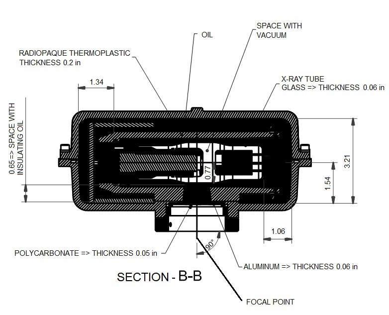
60 UL EN (2001); EN (2001); EN (2001); EN (2001); IEC ; Emenda 1 IEC 601-1; IEC ; CISPR 11, edição 3.1 (1999); IEC (1999); IEC (1998); IEC (1995); IEC (1995); IEC (1996); IEC (1996); IEC series Medical Electrical Equipment - Part 1: General requirements for safety; EN 980:2003 (Ed. 2) - Graphical symbols for use in the labeling of medical devices; ISO Medical devices - application of risk management medical devices; ISO 9687: Dental equipment - graphical symbols; ISO Norma dental units; ISO Quality systems - medical devices; ISO Packaging - pictorial marking for handling goods; ISO Norma dental equipment - connections for supply and waste lines. Reference axis between the target angle and the focal point of the X-ray tube: 90º With axis of anode and cathode, respective Target angle with reference axis: 5º Reference axis angle between the target and the focal point of the x-ray generator mounted: measurements of x-ray generator mounted: 318mm x 440mm x 212mm weight of X-ray generator mounted: 34.6 lb. Tolerances of the focal point in relation in relation to the axes of reference: X= 0.5mm (lateral) Y= 0.5mm (depth) Z= 0.5mm (height) 59
61 60
62 61
63 62
64 17.6. IRRADIATED FIELD SIZE - ANALOG AND DIGITAL PANORAMIC EXAM (PAN: ADULT AND CHILD TMJ MAXILLARY SINUS) IRRADIATED FIELD SIZE DIGITAL CEPH EXAM: 63
65 17.8. IRRADIATED FIELD SIZE ANALOG CEPH EXAM (LATERAL AND LATERAL SIDE 45º) IRRADIATED FIELD SIZE ANALOG CEPH EXAM (POSTERIOR AND ANTERIOR) 64
66 TUBE SPECIFICATIONS Manufacturer TOSHIBA Model D-054 Focus size 0.5 IEC Equivalent filtration ft Al equiv. Anode angle 5 º Anode material Tungsten Maximum voltage 105 kvp Thermal capacity 30 kj Max thermal capacity and cooling time See graphic thermal curve on item curve Maximum current 24mA rectified by half or whole wave and 20mA constant potential Maximum filament current 4.0A / 8.0V Frequency DC Maximum exposure time 20s Max anodic power 680kW COOLING TIME BY TECHNIQUE USED kv Utilized MA Utilized Cooling time corresponding to each of the second issue 60kV 6.3mA 13.2 sec. 62.5kV 6.3mA 13.8 sec. 65kV 6.3mA 14.3 sec. 67.5kV 6.3mA 14.9 sec. 70kV 6.3mA 15.4 sec. 72.5kV 6.3mA 16 sec. 75kV 6.3mA 16.5 sec. 77.5kV 6.3mA 17.1 sec. 80kV 6.3mA 17.6 sec. 82.5kV 6.3mA 18.2 sec. 85kV 6.3mA 18.8 sec. 60kV 8mA 17.6 sec. 62.5kV 8mA 18.4 sec. 65kV 8mA 19.1 sec. 67.5kV 8mA 19.9 sec. 70kV 8mA 20.6 sec. 72.5kV 8mA 21.3 sec. 75kV 8mA 22.1 sec. 77.5kV 8mA 22.8 sec. 80kV 8mA 23.5 sec. 82.5kV 8mA 24.3 sec. 85kV 8mA 25 sec. 65
67 ELECTROMAGNETIC EMISSIONS Manufacturer s guidelines and declaration - electromagnetic emissions The ENCOMPASS Panoramic X-Ray Machine has been designed for use in electromagnetic environments, according to the specifications below. The client or X-Ray Machine operator must ensure that the equipment is used in such type of environment. Emission assays Compliance Electromagnetic Environment Guidelines RF emissions ABNT NBR IEC CISPR 11 RF emissions ABNT NBR IEC CISPR 11 Harmonic emissions IEC Emissions due to voltage/scintillation fluctuation IEC Group 1 The ENCOMPASS Panoramic X- Ray uses RF energy only for its internal functions. However, RF emissions are very low and are not likely to cause any interference with electronic equipment nearby. Class A The ENCOMPASS Panoramic X- Ray Machine is suitable for use in Class A all types of facilities, including residential facilities and those directly connected to the public In compliance system of low -voltage electric power supply for residential buildings. RF emissions CISPR 15 In compliance The ENCOMPASS Panoramic X- Ray Machine is not suitable for inter-connection with another piece of equipment ELECTROMAGNETIC IMMUNITY Manufacturer s guidelines and declaration - electromagnetic immunity The ENCOMPASS Panoramic X-Ray Machine has been designed for use in electromagnetic environments, according to the specifications below. The client or X-Ray Machine operator must ensure that the equipment is used in such type of environment. Immunity Assays ABNT NBR IEC Compliance Level Electromagnetic Electrostatic discharge (ESD) IEC Fast electric transients /pulse train ( Burst ) IEC Assay Level ± 6 kv by contact ± 8 kv by the air ± 2 kv on the mains supply line ± 1 kv on the input/output line 66 ± 6 kv by contact ± 8 kv by the air ± 2 kv on the mains supply line ± 1 kv on the input/output line environment -Guidelines Floors must be finished with wood, concrete or ceramics. In case the floor is covered with synthetic material, relative humidity must be at least 30%. The quality of power supply must be that of hospital facilities or of typical business facilities.
68 Impulses IEC Voltage drops, short interruptions and voltage variations on the mains supply input lines IEC ±1 kv - differential mode ± 2 kv - regular mode < 5% Ut (>95% of voltage drop in Ut) per 0.5 cycle 40% Ut (60% of voltage drop in Ut) per 5 cycles 70% Ut (30% of voltage drop in Ut) per 25 cycles <5% Ut (>95% of voltage drop in Ut) per 5 seconds ±1 kv - differential mode ± 2 kv regular mode < 5% Ut (>95% of voltage drop in Ut) per 0.5 cycle 40% Ut 60% of voltage drop in Ut) per 5 cycles 70% Ut (30% of voltage drop in Ut) per 25 cycles <5% Ut (>95% of voltage drop in Ut) per 5 seconds The quality of power supply must be that of hospital facilities or of typical business facilities. The quality of power supply must be that of hospital facilities or of typical business facilities. In case the user of the ENCOMPASS Panoramic X-Ray Machine required continuing operation during power supply interruption, the equipment should be supplied by an uninterrupted source or battery. Magnetic field in the mains supply frequency (50/60 Hz) IEC A/m 3A/m Magnetic fields in the mains supply frequency should be in similar levels to those of a typical hospital or business facility. Note: Ut is the mains supply AC voltage prior to the application of the assay level. Manufacturer s guidelines and declaration - electromagnetic immunity The ENCOMPASS Panoramic X-Ray Machine has been designed for use in electromagnetic environments according to the specifications below. The client or X-Ray Machine operator must ensure that the equipment is used in such type of environment. Immunity Assays IEC Assay Level Compliance Level Electromagnetic environment - Guidelines Portable and movable RF communication equipment must not be used near any of the parts of the ENCOMPASS Panoramic X-Ray Machine, including cables, with a shorter separation distance than recommended, calculated from the equation applicable to the transmitter s frequency. Recommended Separation Distance. Conducted RF IEC Vrms 150 khz up to 80MHz 3 Vrms d = 1.2 P 67
69 Radiated RF IEC V/m 80 MHz up to 2.5 GHz 3 V/m d = 1.2 P - 80 MHz up to 800 MHz d = 2.3 P MHz up to 2.5 GHz, where P is the transmitter s maximum nominal output power in watts (W), according to the transmitter s manufacturer, and d is the recommended separation distance in meters (m). It is recommended that the field intensity established by the RF transmitter, as determined by an electromagnetic inspection on the site, a should be less than the compliance level in each frequency range. b Interference may occur around the equipment marked by the following symbol: NOTE 1: In 80 MHz and 800MHz, the higher frequency range is applied. NOTA 2: These guidelines may not be applicable in all situations. Electromagnetic propagation is affected by absorption and reflection by structures, objects and people. a Field intensities established by fixed transmitters, such as stations for base radio, telephone (cellular/wireless), mobile ground radios, amateur radio, AM and FM radio transmission and TV broadcast cannot be theoretically predicted accurately. In order to evaluate the electromagnetic environment due to fixed RF transmitters, an electromagnetic inspection of the site is recommended. If the measurement of the field intensity on the site where the ENCOMPASS Panoramic X-Ray Machine is used exceeds the applicable RF compliance level described above, the equipment s operation should be checked in order to ensure it is within normal standards. In case abnormal performance is observed, additional procedures, such as re-orientation and replacement of the ENCOMPASS Panoramic X-Ray Machine may be required. b It is recommended that field intensity should be lower than 3 V/m above the frequency range of 150 khz to 80 MHz. Recommended separation distances between portable and mobile RF communication equipment and the ENCOMPASS Panoramic X-Ray Machine The ENCOMPASS Panoramic X-Ray Machine has been designed for use in electromagnetic environments where RF radiated perturbations are controlled. The client or user of the ENCOMPASS Panoramic X-Ray Machine can help prevent electromagnetic interference by keeping a minimum distance between portable and movable RF communication equipment (transmitters) and the ENCOMPASS Panoramic X-Ray Machine, as recommended below, according to the maximum output power of the communication equipment. Maximum nominal output power of the transmitter (W) Separation distance according to the transmitter s frequency (m) 150 khz up to 80 MHz 80 MHz up to MHz up to 2.5 GHz d = 1.2 P MHz d = 2.3 P d = 1.2 P
70 For transmitters with maximum nominal output powers that are not listed above, the recommended separation distance d in meters (m) can be determined by using the equation applicable for the transmitter s frequency, where P is the transmitter s maximum nominal output power in watts (W) according to the transmitter s manufacturer. NOTE 1: In 80 MHz and 800MHz, the separation distance for the higher frequency range is applied. NOTA 2: These guidelines may not be applicable in all situations. Electromagnetic propagation is affected by absorption and reflection by structures, objects and people. WARNING WARNING THE EQUIPMENT SHOULD NOT BE USED ADJACENT TO OR STACKED ON OTHER EQUIPMENT, RECOMMENDATIONS OF THIS MANUAL MUST BE FOLLOWED. TO ENSURE SAFE OPERATION, THE OPERATOR MUST TURN AWAY FROM EQUIPMENT FOR SAFETY TO AVOID COLLISION WITH MOVING PARTS. THE PATIENT SHOULD BE INFORMED OF ALL MOVEMENTS THAT THE EQUIPMENT WILL PERFORM. THE PATIENT SHOULD ALSO BE TOLD NOT TO MOVE DURING THE EXPOSURE. IT IS THE RESPONSIBILITY OF THE OPERATOR TO WATCH THE PATIENT AND INTERRUPT THE EXPOSURE IN SUCH EVENTS. IMPORTANT: THE STRENGTH OF THE MOVEMENT IS NOT ENOUGH TO HARM THE OPERATOR OR PATIENT. WARNING DO NOT USE ACCESSORIES, TRANSDUCERS, PARTS OF INTERNAL COMPONENTS AND CABLES OTHER THAN THOSE SPECIFIED AND PROVIDED BY THE MANUFACTURER. DOING SO CAN RESULT IN INCREASED EMISSIONS OR DECREASED IMMUNITY OF THE ESE. 69
71 CHARACTERISTIC COOLING OF THE X-RAY GENERATOR CHARACTERISTIC CURVES OF THE X-RAY TUBE. 70
72 Exposition Time 71

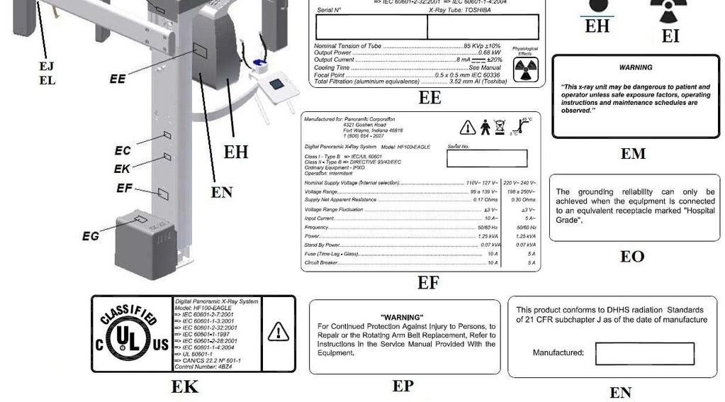
73 LABELS OF IDENTIFICATION 72

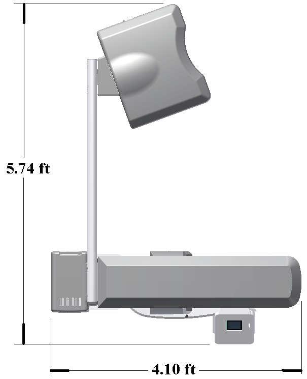
74 EQUIPMENT DIMENSIONS 73
Model: HF100-Eagle USER S MANUAL
 Model: HF100-Eagle USER S MANUAL THIS PAGE WAS INTENTIONALLY LEFT BLANK 1 TABLE OF CONTENTS 1. INTRODUCTION... 6 2. SYMBOLS... 7 3. WARNINGS AND PRECAUTIONS... 8 3.1. WARNINGS AND/OR CAUTION DURING TRANSPORTATION
Digital Panoramic X- Ray unit. Product Data
 Digital Panoramic X- Ray unit Product Data Standard examination programs Standard panoramic: adult/child panoramic exam TMJ open/close mouth: 4 slices are taken in the same image (left/right condyle, open/close
CS 9300 Family User Guide Including
 CS 9300 Family User Guide Including CS 9300 CS 9300 Select Notice Congratulations on purchasing this unit of the CS 9300 Family. Thank you for your confidence in our products and we will do all in our
Message from President 2. What is Full Face Imaging 3. Working with Full Face Imaging 4. Imax-Easy (Owandy) 5. Panoramic Examination 11-15
 5. Panoramic Examination 11-15") Table of Contents Message from President 2 What is Full Face Imaging 3 Working with Full Face Imaging 4 Imax-Easy (Owandy) 5 Software (Apteryx) 6-10 Panoramic Examination 11-15 Remote Control 12 TMJ1 Examination
Table of Contents Message from President 2 What is Full Face Imaging 3 Working with Full Face Imaging 4 Imax-Easy (Owandy) 5 Software (Apteryx) 6-10 Panoramic Examination 11-15 Remote Control 12 TMJ1 Examination
Invisible sophistication. Visible simplicity. CS Welcome to the simplicity of compact panoramic imaging
 Invisible sophistication. Visible simplicity. CS 8100 Welcome to the simplicity of compact panoramic imaging Introducing the CS 8100 The Carestream Dental Factor Humanized technology We keep our technology
OPERATOR S INSTRUCTIONS (for USA & Canada)
") MODEL 097 DENTAL X-RAY OPERATOR S INSTRUCTIONS (for USA & Canada) WARNING This X-ray equipment may be dangerous to patients and operators unless safe exposure factors and operating instructions are observed.
MODEL 097 DENTAL X-RAY OPERATOR S INSTRUCTIONS (for USA & Canada) WARNING This X-ray equipment may be dangerous to patients and operators unless safe exposure factors and operating instructions are observed.
CS 8100 and CS 8100 Access. User Guide
 CS 8100 and CS 8100 Access User Guide Notice Congratulations on your purchase of the CS 8100 and CS 8100 Access. Thank you for your confidence in our products and we will do all in our power to ensure
Table 1. Placing the Sensor in the Sensor Cradle. Step Instruction Illustration
 Table 1. Placing the Sensor in the Sensor Cradle Step Instruction Illustration 1. A. Check "U-shaped" Positioner. The number pointing towards the Sensor (1 or 2) must correspond with the Sensor's size.
KODAK 9000C AND KODAK 9000C 3D Extraoral Imaging System. User Guide
 KODAK 9000C AND KODAK 9000C 3D Extraoral Imaging System User Guide Notice Congratulations on your purchase of the KODAK 9000C and KODAK 9000C 3D Extraoral Imaging System. Thank you for your confidence
Veraviewepocs 2D High Speed Panoramic X-Ray Crystal Clear Images with Reduced Radiation
 Diagnostic and Imaging Equipment Treatment Units Handpieces and Instruments Endodontic Systems Laser Equipment Laboratory Devices Veraviewepocs 2D High Speed Panoramic X-Ray Crystal Clear Images with Reduced
Atomscope PORTABLE VETERINARY X-RAY EQUIPMENT INSTRUCTION MANUAL. Version 1.0
 Atomscope PORTABLE VETERINARY X-RAY EQUIPMENT INSTRUCTION MANUAL Version 1.0 Thank you for purchasing our HFX90V portable veterinary x-ray unit. We are confident that you will be pleased with the radiographs
2100 Intraoral X-Ray System. User s Guide
 2100 Intraoral X-Ray System User s Guide Notice Congratulations on your purchase of the KODAK 2100 Intraoral X-ray System. Thank you for your confidence in our products and we will do all in our power
PROVECTA V. Veterinary X-Ray System. Operator s Manual
 PROVECTA V Veterinary X-Ray System Operator s Manual TABLE OF CONTENTS Introduction....................................................... 4 Warranty..........................................................
ART Plus Dental Panoramic X-Ray Operator s Manual
 ART Plus Dental Panoramic X-Ray Operator s Manual Blue X Imaging Srl Via Idiomi 1/8-33 20090 Assago ITALY e-mail bluex@bluex.it for Oy AJAT Ltd Tietotie 3 FIN-02150 Espoo Finland ajat@ajat.fi Symbols on
DENTAL LINE. Dental Panoramic - Digital & Film
 DENTAL LINE Dental Panoramic - Digital & Film Evolution comes from experience Rotograph Evo takes the experience of five decades of dedication to X-ray diagnostic imaging to the next level. You can rely
D C 01/2019 3
 D-0117968-C 01/2019 3 4 D-0117968-C 01/2019 Screw Driver Screw Driver Unplug both the Red & Blue connectors. (see above) Place a small flat head screw driver on the small orange tabs and push down while
PC-1000/Laser 1000 User Manual Panoramic Corporation Dental Panoramic/Cephalometric X-ray Machine
 PC-1000/Laser 1000 User Manual Panoramic Corporation Dental Panoramic/Cephalometric X-ray Machine PMC6000 PMC6000 Rev Rev D C Table of Contents Table of Contents...2 Introduction... 3-4 Purpose... 3 Statement
KODAK 2200 Intraoral X-ray System. User s Manual
 KODAK 2200 Intraoral X-ray System User s Manual This document is originally written in English. Manual Name: KODAK 2200 Intraoral X-ray System, User Guide Document code: SM731 Revision Number: Rev 01 Printed
KODAK RVG 6100 and 5100 Digital Radiography Systems
 Guide_RVG6100_5100_GB 21/08/06 14:31 Page 1 Quick Start Guide KODAK RVG 6100 and 5100 Digital Radiography Systems Guide_RVG6100_5100_GB 21/08/06 14:31 Page 2 Warnings & Safety Instructions Always use the
NEWTOM GO 2D GREAT.VISION
 CEFLA s.c. Via Selice Provinciale 23/a 40026 Imola Italy t. +39 045 8202727 045 583500 info@newtom.it newtom.it 05/2018 NGO2GB181S00 According to the standards in force, in extra-eu areas the availability
CS 9300C. User Guide
 CS 9300C User Guide Notice Congratulations on your purchase of the CS 9300C. Thank you for your confidence in our products and we will do all in our power to ensure your complete satisfaction. The User
Dental Line. Digital Panoramic System. radiology ahead
 Dental Line Digital Panoramic System radiology ahead next generation digital panoramic unit Cutting-edge technology and design Rotograph Prime is the first in a new generation of digital panoramic units,
OPERATOR'S INSTRUCTIONS DENTAL X-RAY MODEL 096
 DENTAL X-RAY MODEL 096 OPERATOR'S INSTRUCTIONS 0197 WARNING: This X-ray equipment may be dangerous to patients and operators unless safe exposure factors and operating instructions are observed. R Table
MedRx Avant Polar HIT AH-I-MPHITS-5 Effective 11/07/11
 INSTALLATION MANUAL 2 Contents Getting To Know Your AVANT POLAR HIT TM... 4 Setting up the System... 6 Software Installation... 7 Driver Installation Windows 7... 10 Driver Installation Windows XP... 13
User Manual. Model: / UMF20000 Rev A
 User Manual Model: 801125-1/801125-2 UMF20000 Rev A www.pancorp.com 800.654.2027 Table of Contents Introduction 3-5 Purpose 3 Statement of Compatibility 3 Safety Standards 4 Warning of Voltage Regulators
Picasso-Trio 3-D Dental Imaging
 Picasso-Trio 3-D Dental Imaging Digital Panoramic & Cephalometric, CBCT X-ray Imaging System 3 in 1 System Product Data Model Picasso-Trio - NP Panoramic only [CT upgradeable] Picasso-Trio - NC Panoramic
T h e D e n t a l C o m p a n y. Vario DG. Operating Instructions. English
 T h e D e n t a l C o m p a n y Vario DG Operating Instructions English Vario DG Operating Instructions English Edition Version 140509 May 2014 Code 69 553 00110 - D3567 Printed 06/08/2014 11:19:00 Manufactured
ROTOGRAPH PLUS. User's manual. (120V version) Release 07 May 2012 (Rev. 5)
 Release 07 May 2012 (Rev. 5)") ROTOGRAPH PLUS (120V version) User's manual Release 07 May 2012 Revision history Revision history Manual code 6908916000 Rev. Date Page/s Modification description 0 - - First release 1 15.01.01 All Complete
ROTOGRAPH PLUS (120V version) User's manual Release 07 May 2012 Revision history Revision history Manual code 6908916000 Rev. Date Page/s Modification description 0 - - First release 1 15.01.01 All Complete
FONA XPan DG Plus. Operating Instructions. English
 FONA XPan DG Plus Operating Instructions English Dear Customer Responsibilities of the User Thank you for purchasing your new FONA XPan DG Plus X-ray unit for panoramic and cephalometric radiography. For
OPERATOR'S INSTRUCTIONS DX-073 DENTAL X-RAY
 DENTAL X-RAY DX-073 Wall Mount Type...WK Ceiling Mount Type...CK Floor Mount Type...FK1/2 Mobil Mount Type...FM Room Mount Type...RKII OPERATOR'S INSTRUCTIONS 0197 WARNING : This X-ray equipment may be
Performance Meets Simplicity
 Performance Meets Simplicity Cone Beam 3D Imaging Systems P Panoramic X-ray Systems Intraoral X-ray Systems Digital Intraoral Sensors Digital X-ray Phosphor Plates Intraoral Cameras Imaging Software One
RADIOGRAPHY TERMS TO KNOW SELF STUDY DENTALELLE TUTORING
 RADIOGRAPHY TERMS TO KNOW SELF STUDY DENTALELLE TUTORING PLEASE NOTE You DO NOT need to study these for the board exam if this is why you bought our Radiography course, however if you come across any terms
Neo Ultrasound Module Manual
 Neo Ultrasound Module Manual Installation Instructions For complete User Operating Instructions, including Cautions, Warnings, Dangers, Indications, and Contraindications, refer to the User s Manuals.
PantOs 16 XP & PantOs DG xp Panoramic and Cephalometric Dental X-Ray Equipment Operator s Manual
 PantOs 16 XP & PantOs DG xp Panoramic and Cephalometric Dental X-Ray Equipment Operator s Manual Blue X Imaging Srl Via Idiomi 1/8-33 20090 Assago ITALY e-mail bluex@bluex.it Blue X Imaging S.r.l. Via
GE AMX 4+ Portable X-Ray
 GE AMX 4+ Portable X-Ray Typical Manufacturer s Picture GE Healthcare s AMX-4+ analog X-ray system provides high-performance in a compact, easy-to-maneuver package. The rotating arm and tube simplify positioning
KODAK 9500 Cone Beam 3D System. User Guide
 KODAK 9500 Cone Beam 3D System User Guide Notice Congratulations on your purchase of the KODAK 9500 Cone Beam 3D System. Thank you for your confidence in our products and we will do all in our power to
2200 Intraoral X-Ray System. User s Guide
 2200 Intraoral X-Ray System User s Guide Notice Congratulations on your purchase of the KODAK 2200 Intraoral X-ray System. Thank you for your confidence in our products and we will do all in our power
ADAE portable X ray machine Operation manual
 ADAE portable X ray machine Operation manual CONTENTS ABOUT THE SYMBOL----------------------------------------------------------3 INTRODUCTION-----------------------------------------------------------------4
2015 RIGOL TECHNOLOGIES, INC.
 Service Guide DG000 Series Dual-channel Function/Arbitrary Waveform Generator Oct. 205 TECHNOLOGIES, INC. Guaranty and Declaration Copyright 203 TECHNOLOGIES, INC. All Rights Reserved. Trademark Information
impact VC-500LR Monolight INSTRUCTIONS
 impact lighting equipment and accessories VC-500LR Monolight INSTRUCTIONS Congratulations on your purchase of the Impact VC-500LR Monolight. We feel that it will contribute much to your photographic skill
Quolis 5000 Light INSTALLATION AND OPERATION INSTRUCTIONS. Model AL-820 IMPORTANT
 Quolis 5000 Light Model AL-80 INSTALLATION AND OPERATION INSTRUCTIONS IMPORTANT After installation is completed, check all the bolts, screws and fasteners to confirm that they are securely fastened. R
User Manual. FlashRay Sensor. 100 E. Granada Blvd. Suite 219 Ormond Beach, FL Ph: Manual Date pg.
 User Manual FlashRay Sensor 100 E. Granada Blvd. Suite 219 Ormond Beach, FL 32176 Ph: 386-672-0450 800-323-2690 Manual Date 20181010 pg. 1 Table of Contents 1 Introduction... 4 1.1 Indication for Use...
WARNING: We recommend that you consult the Safety, Regulatory and Technical Specification User Guide before using the CS 2200.
 CS 2200 User Guide Notice Congratulations on your purchase of the CS 2200. Thank you for your confidence in our products and we will do all in our power to ensure your complete satisfaction. The User Guide
KODAK Dental Imaging Software. Quick Start Guide
 KODAK Dental Imaging Software Quick Start Guide Notice Congratulations on your purchase of The KODAK Dental Imaging Software. Thank you for your confidence in our products and we will do all in our power
Instruction Manual. Self-Leveling Cross-Line Laser Level Model No and
 3728H_Manuals 9/2/10 8:02 AM Page 1 Self-Leveling Cross-Line Laser Level Model No. 40-6620 and 40-6625 Instruction Manual Congratulations on your choice of this Self-Leveling Cross-Line Laser Level. We
Crossfire Footswitch. User Guide
 Crossfire Footswitch 0475000100 User Guide Contents Warnings and Cautions... 3 Symbol Glossary... 4 Product Description and Intended Use... 6 System Overview...6 Indications/Contraindications...8 Package
#
 INSTALLATION MANUAL 2 Contents Getting To Know Your AVANT POLAR HIT TM... 4 Setting up the System... 6 Software Installation... 7 Driver Installation Windows 7... 10 Driver Installation Windows XP... 13
Installation Operation Care
 Installation Operation Care Designer Roller and Designer Screen Shades Standard and Cassette Cordless Lifting System CONTENTS Getting Started: Product Views... 1 Tools and Fasteners Needed... 3 Installation
CRANEX Novus. Digital Panoramic X-ray Unit. User s Manual. Number ver. 3 (0702)
") CRANEX Novus Digital Panoramic X-ray Unit User s Manual Number 200409 ver. 3 (0702) EN CRANEX Novus Contents CRANEX Novus Digital Panoramic X-ray Unit User s Manual Medical Device Directive 93/42/EEC
CRANEX Novus Digital Panoramic X-ray Unit User s Manual Number 200409 ver. 3 (0702) EN CRANEX Novus Contents CRANEX Novus Digital Panoramic X-ray Unit User s Manual Medical Device Directive 93/42/EEC
DENTAL X-RAY OPERATOR'S INSTRUCTIONS. (for USA) Wall Mount Type...WK
 Wall Mount Type...WK") M 505 DENTAL X-RAY OPERATOR'S INSTRUCTIONS (for USA) Wall Mount Type...WK WARNING This X-ray equipment may be dangerous to patient and operator unless safe exposure factors, operating instructions and
M 505 DENTAL X-RAY OPERATOR'S INSTRUCTIONS (for USA) Wall Mount Type...WK WARNING This X-ray equipment may be dangerous to patient and operator unless safe exposure factors, operating instructions and
Efficiency with elegance
 ENGLISH Efficiency with elegance Simple is beautiful. Planmeca designed their fully digital Planmeca ProOne, an all-round dental X-ray unit, with simplicity in mind. Still, no compromises were made in
Tube Facing Tool.
 www.swagelok.com Tube Facing Tool This manual contains important information for the safe and effective operation of the Swagelok TF72 series tube facing tool. Users should read and understand its contents
Rolyan Splint Pan OPERATION MANUAL. Item # Small Item # Large
 Rolyan Splint Pan OPERATION MANUAL Item #081544816 - Small Item #081544808 Large PLEASE READ THIS ENTIRE MANUAL BEFORE OPERATING YOUR NEW SPLINT PAN. Failure to follow these instructions could result in
CDR Wireless / SDX Software User Guide
 CDR Wireless / SDX Software User Guide Schick Technologies, Inc. 30-00 47 th Avenue Long Island City, NY 11101 (718) 937-5765 (718) 937-5962 (fax) PART NUMBER B1051503 REV. Copyright 2004 by Schick Technologies,
CANARY AUDIO. Power Amplifier CA-309 OWNER S MANUAL. Handcrafted in California MADE IN USA
 CANARY AUDIO 300B Push-Pull Parallel Power Amplifier Mono Block Handcrafted in California CA-309 OWNER S MANUAL MADE IN USA Dear Customer: Please allow us to take this opportunity to thank you for purchasing
Table of Contents. Polytel GMA Glucose Meter Accessory Model PWR USER MANUAL Version: 2
 Table of Contents Polytel GMA Glucose Meter Accessory Model PWR-08-03 USER MANUAL Version: 2 Polymap Wireless 310 S. Williams Blvd. Ste. 346 Tucson, Arizona 85711 (520) 747-1811 www.polymapwireless.com
Wireless Z-Wave Control ZRP-100US Z-Wave Repeater USER MANUAL. Introduction
 Wireless Z-Wave Control ZRP-100US Z-Wave Repeater USER MANUAL Introduction Thank you for choosing ZRP-100 Z-Wave Repeater product! ZRP-100 is a Z-Wave repeater with best RF performance to repeat Z-Wave
On-Line Cardio Theater Wireless Digital Transmitter Installation and Instruction Manual
 On-Line Cardio Theater Wireless Digital Transmitter Installation and Instruction Manual Full installation instructions accompany your Cardio Theater equipment order. This On-Line version of our Installation/Instruction
ET-413 2MP USB PEN MICROSCOPE
 ET-413 2MP USB PEN MICROSCOPE USER S MANUAL INTRODUCTION FUNCTIONS AND APPLICATIONS The ET-413 2 Mega-Pixel USB PEN MICROSCOPE is a new electronic product for micro observations. It is a tubular imaging
P a n o r a m i c a n d C e p h a l o m e t r i c X - r a y s
 AN ALL AROUND PERFECT PICTURE. The perfect combination of image quality, efficiency and design. P a n o r a m i c a n d C e p h a l o m e t r i c X - r a y s Air Techniques experts in digital imaging ProVecta
User and Installation Manual. For Tandem Arm and Slim Line Models. Tandem Arm. Slim Line
 Tandem Arm User and Installation Manual For Tandem Arm and Slim Line Models Tandem Arm Slim Line Table of Contents Warnings... 4 Box Contents... 5 Hardware Kits... 6 Parts... 7 Tandem Arm Installation...
Top spin Nr /
 Top spin Nr. 1840 0000 / 1840 1000 Bedienungsanleitung 21-6680 28052014 / A Made in Germany Ideas for dental technology Top spin Nr. 1840 0000 / 1840 1000 Contents 1. Introduction...2 1.1 Symbols...2 2.
LifeGear G1 /HOME GYM ITEM NO.: 63100
 LifeGear G1 /HOME GYM ITEM NO.: 63100 OWNER S MANUAL IMPORTANT: Read all instructions carefully before using this product. Retain this owner s manual for future reference. The specifications of this product
Planmeca Romexis. quick guide. Viewer EN _2
 Planmeca Romexis Viewer quick guide EN 10029550_2 TABLE OF CONTENTS 1 START-UP OF PLANMECA ROMEXIS VIEWER...1 1.1 Selecting the interface language... 1 1.2 Selecting images...1 1.3 Starting the Planmeca
P a n o r a m i c a n d C e p h a l o m e t r i c X - r a y s
 AN ALL AROUND PERFECT PICTURE. The perfect combination of image quality, efficiency and design. P a n o r a m i c a n d C e p h a l o m e t r i c X - r a y s Air Techniques experts in digital imaging ProVecta
INTRODUCTION. 4 SAFETY INSTRUCTIONS. 5 ABOUT THIS DEVICE. 6 FIRST OPERATION. 7 THE DISPLAY. 8 ATTACHING THE WRIST SLEEVE. 9 CORRECT MEASUREMENT.
 Table of contents INTRODUCTION.............................. 4 SAFETY INSTRUCTIONS........................ 5 ABOUT THIS DEVICE.......................... 6 FIRST OPERATION............................ 7
Antenna Splitter ASA 1. Instruction manual
 Antenna Splitter ASA 1 Instruction manual Contents Contents Important safety instructions... 2 The ASA 1 active antenna splitter... 4 Combination possibilities of ASA 1/ASA 1-1G8... 5 Delivery includes...
Table of Contents. Polytel GMA Glucose Meter Accessory for Bayer Ascensia Contour Model PWR USER MANUAL Version: B
 Table of Contents Polytel GMA Glucose Meter Accessory for Bayer Ascensia Contour Model PWR-08-07 USER MANUAL Version: B Polymap Wireless 310 S. Williams Blvd. Ste. 350 Tucson, Arizona 85711 (520) 747-1811
User Manual. Version May 30, 2014 (Rev. 1)
") : User Manual 0051 Version May 30, 2014 Revision history Revision history Manual code 6959902203 03 Rev. Date Page Description of the changes 0 20.02.14 - Document approval 1 30.05.14 15, 25, 28, 29, 52,
: User Manual 0051 Version May 30, 2014 Revision history Revision history Manual code 6959902203 03 Rev. Date Page Description of the changes 0 20.02.14 - Document approval 1 30.05.14 15, 25, 28, 29, 52,
eflex 75x/300x Digital Microscope with Flexible Neck User Guide
 eflex 75x/300x Digital Microscope with Flexible Neck User Guide Table of Contents Important information... 4 Product description... 4 Computer requirements... 5 Windows based PC... 5 Mac OS based PC...
I-Max Touch User's Manual. Version 4 December 2008 (Rev. 1)
") 0459 User's Manual Version 4 December 2008 Contents Contents 1. INTRODUCTION 1 1.1 Icons appearing in the manual... 2 2. SAFETY INFORMATION 3 2.1 Warnings... 4 2.2 Environmental risks and displacement...
0459 User's Manual Version 4 December 2008 Contents Contents 1. INTRODUCTION 1 1.1 Icons appearing in the manual... 2 2. SAFETY INFORMATION 3 2.1 Warnings... 4 2.2 Environmental risks and displacement...
English User's Guide
 User's Guide Imacon Flextight 343 2 2003 Imacon A/S. All rights reserved. Imacon Flextight 343 User's Guide, Part No 70030009, revision B. The information in this manual is furnished for informational
Touch the Future of Digital Panoramic Imaging. Progeny VantagE TM
 Touch the Future of Digital Panoramic Imaging Progeny VantagE TM SIMPLY EXCEPTIONAL The Progeny Vantage Panoramic System sets a new standard in digital panoramic imaging with its advanced technology and
SAVI SCOUT Surgical Guidance System. Console Operation Manual
 SAVI SCOUT Surgical Guidance System Console Operation Manual 2 Copyrights and Trademarks 2016 Cianna Medical, Inc. All rights reserved. Patents pending. Cianna Medical and SAVI are registered trademarks
Rotating Anode X-Ray Tube Housing Assembly. General Data. IEC Classification... Class I
 Technical Data TD ROTANODE E7239X E7239FX E7239GX 197 Rotating Anode X-Ray Tube Housing Assembly Rotating anode X-ray tube housing assembly for the purpose of general diagnostic X-ray procedures. Specially
S5-ADU. Front... 4 Rear... 4
 Trantec ANTENNA DISTRIBUTOR INSTRUCTION MANUAL S5-ADU Thank you for purchasing TRANTEC Antenna Distributor. Please carefully follow the instructions in this manual to ensure long, trouble-free use of your
Rotating Anode X-Ray Tube Housing Assembly. General Data
 Display Devices & Components Company TECHNICAL DATA ROTANODE TM E7252X Rotating Anode X-Ray Tube Housing Assembly! High speed rotating anode X-ray tube housing assembly for high energy radiographic and
Nuclear Associates
 Nuclear Associates 07-424 Digital Densitometer II Operators Manual March 2005 Manual No. 112111 Rev. 4 2003, 2005 Fluke Corporation, All rights reserved. Printed U.S.A. All product names are trademarks
Digital imaging à la carte
 I-Max Plus Digital imaging à la carte Digital imaging à la carte I-Max Plus offers a wide selection of programs. The first Dual System, I-Max Plus provides unmatched advantages that will enhance your standing
Process/Mini. English IMPORTANT NOTE. Installation and Operation Manual. General Purpose Light Curtain with 30 mm resolution
 Installation and Operation Manual Process/Mini General Purpose Light Curtain with 30 mm resolution English manufactured under ISO 9001: 2000 IMPORTANT NOTE FOLLOW THE INSTRUCTIONS GIVEN IN THIS MANUAL
Allegro Home Office Assembly Instructions. Tipping Restraint. Bun Foot W/ Leveler. 4 pcs.
 email: info@riverside-furniture.com Allegro Home Office Assembly Instructions Components and Hardware List Page 1 of 5 Made in China Shelf Pin Wood Shelf File Rod & Clips 1/2"Wood Screw A 16 pcs. B 4 pcs.
С 800 CASSIDA C 800 HIGH SPEED COIN COUNTER
 С 800 CASSIDA C 800 HIGH SPEED COIN COUNTER This manual contains important information on safety measures and operational features. Please read it carefully before operating your coin counter, and keep
Table of Contents. Polytel GMA Glucose Meter Accessory for Abbott FreeStyle Lite and FreeStyle Freedom Lite Model PWR USER MANUAL Version: B
 Table of Contents Polytel GMA Glucose Meter Accessory for Abbott FreeStyle Lite and FreeStyle Freedom Lite Model PWR-08-09 USER MANUAL Version: B Polymap Wireless 310 S. Williams Blvd. Ste. 350 Tucson,
OBSOLETE. Progeny Vantage Panoramic X-ray System. Installation Guide For Vantage units manufactured during or after October 2012
 Progeny Vantage Panoramic X-ray System Installation Guide For Vantage units manufactured during or after October 2012 0120 Part Number: 00-02-1608 ECN: P3179 REV. G Contents Contents... 2 1 Regulatory
LUDLUM MODEL 182 RADON FLASK COUNTER. June 2011 Serial Number PR and Succeeding Serial Numbers
 LUDLUM MODEL 182 RADON FLASK COUNTER June 2011 Serial Number PR206794 and Succeeding Serial Numbers LUDLUM MODEL 182 RADON FLASK COUNTER June 2011 Serial Number PR206794 and Succeeding Serial Numbers LUDLUM
KODAK 9000C and KODAK 9000C 3D Extraoral Imaging System. Installation Guide
 KODAK 9000C and KODAK 9000C 3D Extraoral Imaging System Installation Guide Notice Congratulations on your purchase of the KODAK 9000C and KODAK 9000C 3D Extraoral Imaging System. Thank you for your confidence
SDX User Guide. Schick Technologies, Inc th Avenue Long Island City, NY (718) (718) (fax)
 (718) (fax)") SDX User Guide Schick Technologies, Inc. 30-00 47 th Avenue Long Island City, NY 11101 (718) 937-5765 (718) 937-5962 (fax) PART NUMBER B1051501 REV. B Copyright 2004 by Schick Technologies, Inc. All Rights
SDX User Guide Schick Technologies, Inc. 30-00 47 th Avenue Long Island City, NY 11101 (718) 937-5765 (718) 937-5962 (fax) PART NUMBER B1051501 REV. B Copyright 2004 by Schick Technologies, Inc. All Rights
RadView Manual Collimator
 OPERATOR MANUAL RadView Manual Collimator DEL MEDICAL IMAGING CORPORATION 11550 WEST KING STREET FRANKLIN PARK, IL. 60131 TECHNICAL SUPPORT (847) 288-7000 FAX (847) 288-7011 THIS DOCUMENT CONTAINS INSTALLATION,
Table of Contents. Polytel GMA Glucose Meter Accessory for LifeScan Meters Model PWR USER MANUAL Version: 1
 Table of Contents Polytel GMA Glucose Meter Accessory for LifeScan Meters Model PWR-08-06 USER MANUAL Version: 1 Polymap Wireless 310 S. Williams Blvd. Ste. 350 Tucson, Arizona 85711 (520) 747-1811 Mon-Fri
Installation & Operation Manual SAGA1-K Series Industrial Radio Remote Control
 Installation & Operation Manual SAGA1-K Series Industrial Radio Remote Control Gain Electronic Co. Ltd. Table Of Contents Safety Considerations ------------------------------------------------------------2
Film2USB Converter. Quick Start Guide & User s Manual. Model Number F2USB-05
 Film2USB Converter Quick Start Guide & User s Manual Model Number F2USB-05 www.film2usb.com www.clearclicksoftware.com Table of Contents Safety Precautions... 3 Package Contents... 4 Description of Parts...
Flash Stamp Machine T1511M User Manual
 Flash Stamp Machine T1511M User Manual Declaration of conformity (Europe only) We, Trodat GmbH Linzer Straße 156 A-4600 Wels hereby declare that the Flash Stamp Machine model T1511M is CE certified respectively
Printed on: 09 Apr 2013, 07:01:56 pm; Printed by: TOBIAS BAUER
 Table of Contents Chapter 1 - Introduction System Components... 1-1 Articulated Arm...1-1 Master Control Touch Panel...1-1 Tubehead...1-1 Cone...1-1 Intended Use... 1-2 Users... 1-2 About This Manual...
OPERATOR'S INSTRUCTIONS
 MODEL 096 DENTAL X-RAY OPERATOR'S INSTRUCTIONS (for USA & Canada) Table of contents Page Layout of Control Box... 1 Function of Controls... 2 Operating Procedures... 4 Error Codes... 5 Maintenance... 6
Sarspec, Lda. - Rua Camilo Castelo Branco, 965 PQ Vila Nova de Gaia Phone:
 2 3 IMPORTANT SAFETY NOTE: Before operating this device, please read carefully this User Manual and be familiar with its contents prior to using this equipment. To help avoid potential serious injury to
OPERATOR'S MANUAL JUNE 2017
 OPERATOR'S MANUAL JUNE 2017 TABLE OF CONTENTS PAGE 1.0 INTRODUCTION 2 2.0 WARNINGS 2 DUTY CYCLE 2 STORAGE 2 3.0 PHYSICAL DESCRIPTION 3 HIGH VOLTAGE PULSER/TUBEHEAD 3 BASE 3 BATTERY PACK 3 BATTERY CHARGER
Agilent G1888 Network Headspace Sampler
 Agilent G1888 Network Headspace Sampler Safety and Regulatory Information Agilent Technologies Notices Agilent Technologies, Inc. 2004 No part of this manual may be reproduced in any form or by any means
ARU-01CF Portable X-Ray NSN:
 ARU-01CF Portable X-Ray NSN: 6525-01-468-1672 COMMAND l AIR OPERATION & MAINTENANCE MANUAL Table of Contents Introduction................................................................3 Purpose.............................................................3
EXPLOR-X 70. User's manual. with AP TIME X TIME X timer (120V version) Release 16 March 2001 (Rev. 1)
 Release 16 March 2001 (Rev. 1)") EXPLOR-X 70 with AP TIME X TIME X timer (120V version) User's manual Release 16 March 2001 Contents Contents 1. INTRODUCTION 1 1.1 Icons appearing in the manual... 1 2. SAFETY INFORMATION 2 2.1 Warnings...
EXPLOR-X 70 with AP TIME X TIME X timer (120V version) User's manual Release 16 March 2001 Contents Contents 1. INTRODUCTION 1 1.1 Icons appearing in the manual... 1 2. SAFETY INFORMATION 2 2.1 Warnings...
DM-45 Digital Multimeter
 INSTRUCTION MANUAL DM-45 Digital Multimeter Read and understand all of the instructions and safety information in this manual before operating or servicing this tool. Description The Greenlee DM-45 Digital