Soil Density Gauge Operator s Handbook
|
|
|
- Tiffany Mitchell
- 6 years ago
- Views:
Transcription


1 Soil Density Gauge Operator s Handbook
2 Table of Contents Introduction 3 Measurement Technology 3 Application Summary 4 Safety 4 Operating Requirements 4 Controls & Components 5 Contents 5 Gauge Features 6 External Controls 7 Power Save/Auto Shut Down 8 Part 1: Setting up the SDG 8 Installing/Charging the Battery 9 Start Software 10 Main Menu 11 Local Time and Change Date Format 12 Setup GPS 13 Control Menu 14 Select Measurement Units 15 Data Logging 15 Project Details 15 Define, Edit or Upload Material Properties 17 Define and Editing a Material 18 Setting Measurement Offsets 20 Determining Offset Values 22 Upload Material 23 Part 2: Running a Test 24 Measurement Pattern 24 Surface Preparation 24 Measure Density 25 Select a Different Material to Test 28 Part 3: Data Storage and Downloading Data 29 Measurement Data 29 Diagnostic Data 29 Storage Capacity 30 Downloading Data 30 Deleting a Project File 30 Part 4: Maintenance and Troubleshooting 31 Maintenance 31 Troubleshooting 33 Part 5: Definitions and Calculations 33 Measurement Results 33 Definition of Material Properties 34 Part 6: Standardization of SDG 35 Part 7: Explanation of Gradation and Compaction Reports 36 SDG Unit Warranty 44 2
3 Introduction TransTech s Soil Density Gauge (SDG) utilizes state of the art technology to get accurate soil density readings. It s primary features are: No special license or radioactive materials required. Lightweight and easy to use. 12 hours of portable operation. Measures density in common units (pcf or kg/m³). Measures percent moisture. Stores volumes of readings on internal data logger. Data download via USB flash drive (semicolon delimited text file format). Measurement Technology Using electrical impedance spectroscopy (EIS) the SDG 200 s measurement permits separation of the effects of density and moisture content on the response of the soil to electromagnetic probing. The density, or compaction level, is measured by the response of the SDG 200 s electrical sensing field to changes in electrical impedance of the material matrix. Since the dielectric constant of air is much lower than that of the other soil constituents, as density/compaction increases, the combined dielectric constant increases because the percentage of air in the soil matrix decreases. The SDG 200 performs a calculation on the measurement data that enables the device to report the soil s density and moisture content. 3
4 Application Summary The SDG 200 is intended primarily for making density measurements on a standard 12 inch lift of soil during or after compaction. It is designed to measure coarse and fine grained materials common in standard soils used in civil construction projects. After configuring the gauge with soil properties from a standard particle size distribution report (ASTM D422) and Proctor test (ASTM D698 and D1557) the gauge will provide reliable and consistent measurements. Safety Every effort has been made to make the Soil Density Gauge SDG 200 convenient to use and inherently safe. The SDG 200 uses non-nuclear, low-voltage direct current to obtain measurements, therefore, there are no badges, licensing, storage or transport concerns. Like any instrument, however, the user should exercise care and common sense in its use to prevent mishaps. Warning Do not use the unit on or near electrical wiring. A potential shock hazard exists if contact is made with the exposed wiring. Warning Use care in handling the unit. Personal injury can occur through improper handling. Take proper care to avoid accidentally dropping the unit. Warning Unauthorized disassembly of the unit will void the warranty. Warning Shipping the gauge with the batteries inside is not recommended. Caution Charging the gauge overnight or unattended is not recommended Caution Turn the unit off when not in use and during transport. Caution Be sure not to switch standardization plates with other gauges. Check the Serial Numbers located on the gauge and on the plate to be sure they match. Operating Requirements Temperature: -4 to 104 F (-20 to 40 C) Relative Humidity: 10% to 90% noncondensing Note: Exposing the equipment to high altitude OR extreme temperature may reduce life of the equipment. Disclaimer: TransTech reserves the right to change or modify product design, construction, specifications, or materials without prior notice and without incurring any obligation to make such changes and modifications on TransTech products previously or subsequently sold. 4


5 Controls and Components Contents The SDG200 is packaged and shipped with the following components. Contact TransTech Systems Inc. Customer Service if any of the parts are missing. SDG200 unit Storage/shipping case Operators Quickstart Guide SDG handle 120/220V AC to 12V DC battery charger 12V DC Car Charger 3 battery packs 5
 Handle Used to carry the gauge Handle Extension Used")


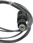
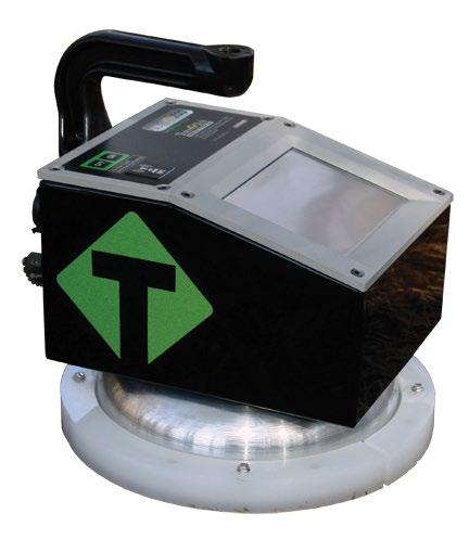
6 Gauge Features On\Off Button Turns gauge on and off GPS Module Location of GPS unit on the gauge (Accurate to 5+- Meters) Handle Used to carry the gauge Handle Extension Used to connect handle extension TouchScreen Used to input and interact with the gauge Faceplate Protective bezel for touchscreen Gauge Shell Body of the gauge Reflective Vinyl safety feature for operation in dark areas Shroud with 10 Sensor Plate Location where sensor plate is located USB Port Used to allow communication between a flash drive and the gauge Charger Port used to connect the ac or dc charger to gauge Infrared Temperature Sensor Used to measure the surface temperature of the asphalt Battery Door where the battery is located 6

7 External/Internal Controls External controls on the SDG 200 consist of an ON/ OFF switch and 480x640 VGA touch screen display for navigating through the user interface and entering alpha/numeric data. Be sure not to drag your finger from one button to the next. A firm yet light touch is all that is needed to navigate from screen to screen. Unique yet consistent icons are located on most screens for easy one touch navigation. When data input is required of the operator the screen will display the above keyboard. Toggle from upper to lower case letters using the Shift button The upper case keyboard gives the option of a minus sign while the lower case keyboard gives the plus sign Once editing is completed simply Press Enter to store and return to the previous screen. 7
 and will continuously update the remaining voltage of the batteries while displaying the date, time and status")
8 External/Internal Controls The numeric keypad as shown in this example allows for only numbers and a decimal point. Press Accept to store your entry and in most cases return to the previous screen. The Status Bar is located at the bottom of the screen (excluding the keyboard screens) and will continuously update the remaining voltage of the batteries while displaying the date, time and status of the GPS and Data Logging features. Power Save/Auto Shut Down The SDG Model 200 has a built in power saving mode. If there are no buttons pressed after approximately 20 minutes the unit will go into a power saving mode. Pressing any key will Wake the SDG up for continued use. If the SDG is left On for an hour without any buttons being pressed, it will shut itself down, to conserve battery run time 8 Setting up the SDG 200 Prior to using the SDG 200 for the first time the gauge will need to be configured to make measurements and record data correctly. The following steps must be completed before operating the SDG 200: 1. Installing and Charging the Batteries 2. Starting the Software 3. Set the Local Time/Set Date 4. Set up the GPS 5. Select Units of Measurement 6. Define the material being tested (Material Details) 8. Define Project Details

 Turn the SDG 200 unit OFF. 2) Connect the charger to the charger connector located on the back of the SDG 200.")
9 Installing/Charging the Batteries You will find a plate on the back of the SDG 200 with 4 spring loaded bolts. Turn each bolt approx. 2 full turns until the spring releases Remove the plate from the gauge Next you will find a wire with a connector, disconnect the battery from the gauge Then pull the nylon strap to slide the battery out of the compartment. (Do Not pull the battery by the connector wire, doing so could cause damage to the battery) Plug the gauge in and allow the LED to go from red to green for a full charge. Approximate charge time is 4 hours. To charge the unit, proceed as follows: 1) Turn the SDG 200 unit OFF. 2) Connect the charger to the charger connector located on the back of the SDG ) Plug the charger into a standard AC outlet. 4) The red indicator lamp will turn green to indicate that the batteries are charged. 5) Unplug the charger from the power source before disconnecting the charger from the SDG

10 Installing/Charging the Batteries Battery voltage can be viewed on the Status Bar located at the bottom of all screens. A fully charged battery will display over 8 volts. The battery voltage will decrease as the SDG 200 is used. A low battery icon will be displayed at approximately 6.5 volts. The gauge will continue to operate until the battery can not supply enough voltage to complete a measurement. Once this happens, the gauge will automatically shut down and will not restart until charged. Depending on the condition of the batteries, once the voltage drops below 6 volts, the gauge may be able to take about 12 to 15 additional readings. It is important to re-charge the battery after each use. Starting the Software Turn the SDG 200 on by pressing the ON button. After a few seconds the TransTech splash screen will appear followed by the Main Menu Screen. The Main Menu screen will display six options. Start SDG200, Internet (Coming Soon), Calculator, Contact TransTech, GPS Control and Update Software. 10


11 Main Menu Start button when pressed will open the Control Menu Screen. The Calculator button when pressed will open a screen which functions as a calculator. The GPS Control button when pressed will open a screen which will allow you to enable or disable the GPS. The Internet button when pressed will open a new screen. The new screen indicates that this will be an option in the future. It is not active at this time. The Contact button when pressed displays TransTech and distributor contact information. The Update Software button will be used in the event that TransTech releases an update to the software Local Time and Change Date Format You may set the date and time in two locations. From the Main Menu, Press Set Time & Date located on the status bar or from the Control Menu press Date & Time. 11


12 Local Time and Change Date Format To set the time, Press Set Time. Press the appropriate numbers for the time in 24 hour format. Once you are satisfied with your entry, Press Accept to store and return to the previous screen. To set the date, Press Set Date. The date will display in either the DD/MM/YY or MM/DD/YY format which may be toggled from the button located on both screens. As you did with the time, press the appropriate numbers for the date in the format chosen. Press Accept to store and return to the previous screen. (Note: Date will be preset by the factory) 12

 grid to Latitude/ Longitude (LAT-LON).")
 in both formats.")
13 Setup the GPS Setting up the GPS is nothing more than turning it on and waiting to connect to satellites. It can take up to 15 minutes to connect to satellites depending on your location. From the Main Menu, Press GPS CONTROL. GPS status can be toggled ON or OFF. When the GPS is ON the satellite dish on the status bar turns from red to green. GPS formatting can also be toggled from the Universal Transverse Mercator (UTM) grid to Latitude/ Longitude (LAT-LON). Initially the display will read Sats 0 for both formats until connections have been made. The above examples show a connection to five satellites (Sats 5) in both formats. GPS locations will appear on the bottom left corner of all Reading Mode screens and will store with each reading when Data Logging is ON. 13


14 Control Menu From the Main Menu Press Start SDG 200 the icons listed below. to obtain the Control Menu. From this menu, you will find Opens the material details screen Starts the standardization process Opens the project details screen Opens the diagnostics screen Opens the data management screen. Here you can delete, download and print job files Opens the date and time screen Opens the units screen. Here you can toggle, kg/m 3 -lbs/ft 3, F -C, in-mm Starts the measurement process 14


15 Select Measurement Units From the Control Menu, Press Units. Density, Temperature and Depth can be toggled independently between System International (SI metric ) and U.S. Customary Units. For example, you can set your Density in lb/ft 3 while the Temperature is set for Celsius and Depth set to Inches. Press Control Menu on the taskbar to return to the Control Menu. Data Logging The SDG 200 saves data automatically under the Project name that is current while readings are being taken. Data stored includes all Project and Mix details as well as Dry Density, Wet Density, Percent Moisture, Volumetric Moisture, Percent Compaction, Soil Temperature, Date, Time, GPS Position, GPS Time and GPS Date. Project Details The SDG 200 is configured to store 10 unique projects that are identified by user entered descriptions. If 10 projects have been defined in the SDG 200 and an 11th project is required, one of the original 10 will need to be modified to reflect the new project. The details of the new project will need to be input by editing the details of a previously stored project. Once the old projects are overwritten with new information, the old information is gone and the new information is saved in the gauge. Previously store data files with the old material information, however, will not be overwritten. You may revisit each Project at any given time to continue taking readings. Data from readings taken within each project will store in the order of which they were taken. If material details change within a project or project details are added, data for readings taken after the changes will continue to store in the same data file in the order of which they were taken. Only by changing the Project Name itself will the data be stored in a separate data file. 15
16 Project Details The default Projects stored in a new SDG 200 will have generic Project names (i.e. Project1, Project2, etc) along with generic Project details (i.e. My Street, My Road, Contact). Project Detail screens will resemble the Material Detail screen such that you are able to select your Project using the up and down arrows. The green highlighted project is the CURRENT PROJECT. Readings taken will store in a data file using the CURRENT PROJECT NAME. If the gauge is shutdown, the current project prior to shutdown will remain the current project when started back up. Keep track of your projects by entering detailed information into Project Details. Editing Project Details From the Control Menu, Press Project for the Project Details screen. The project highlighted in green on the left is displayed in detail on the right. To edit the details of this project, Press Edit Project. 16

17 Editing Project Details There are four black buttons labeled Project Location Location Contact. By pressing one of these labeled buttons, you will enter the screen that allows you to store information for that Project. For example Press Project, a keyboard allowing you to change the default name will appear. Press Clear if you would like to start over with a new name. Press Shift to toggle from lower to upper case letters. Once editing has been completed, Press Enter. Define, Edit or Upload Material Properties The density determined by the SDG 200 is highly material dependent so it is extremely important that the material properties from the Proctor Test and Gradation Report for the soil being tested are input accurately into the gauge. The SDG 200 is configured to store 20 unique materials that are identified by user entered descriptions. If 20 materials have been defined in the SDG 200 and a 21 st material is required, one of the original 20 will need to be modified to reflect the material properties of the new material. The properties of the new material will need to be input by editing the properties of a previously defined material. Once the old material properties are overwritten with new information, the old information is overwritten and the new information is saved in the gauge. The SDG 200 will have default defined materials stored in each of the 20 unique locations. The following sequence explains how to input new material properties through the keypad or by USB upload and how to edit previously input material definitions. 17
18 Define, Edit or Upload Material Properties Note: Be sure that the units of the gauge are set for the same units as the material you are uploading. If, for example, the gauge was set in U.S. Customary units (ex: 150 lb/ft3) and you were to upload the material in SI units ( kg/m3) the gauge will notify you that the density is out of range. However, it will continue to load the material. If you were to switch to SI units AFTER the material has been loaded, the density would convert the as if it were in lb/ft3 and result in 38,489.2 kg/m3. Correct this by deleting the material, change the units of the gauge and reload the material or by simply editing the density in the material setup. See Part 5 for explanations of the Material Properties. See Part 6 for explanations of gradation and Proctor test reports. See Appendix A for explanations of the MTL Generator Defining and Editing a Material Here you may use the green up or down errors to select a new material for editing or change an existing material. The green highlighted material is the CURRENT MATERIAL that the gauge will use when taking readings. Prior to exiting this screen, be sure this is the material you want and the information to the right has been verified. Press Control Menu on the Status Bar (bottom middle) to return to the Control Menu. If the gauge is shutdown, the current material prior to shutdown will remain the current material when started back up.!! Note: The sum of %Greater the 3 inches, %Gravel, %Sand, and %Fines must add up to 100%. The default values programmed in the SDG software add up to 100%. As soon as one of those values is edited, the sum will no longer add up to 100% and an error message will be displayed, however, after the initial error the gauge will allow you to exit and begin taking readings. THIS IS NOT RECOMMENDED AND WILL GIVE INACCURATE RESULTS!!!! Note that Max Dry Density and Dry Density Offset must be entered in the same units in which the gauge is configured to output results. Example: If the gauge is configured to measure in pcf, input Max Dry Density in pcf!! 18

19 Defining and Editing a Material From the Control Menu, Press Material for the Material Details screen. The material highlighted in green on the left is displayed in detail on the right. To edit the details of this material, Press Edit Material. There are fifteen material properties for each material. Eight of these material properties are listed on Page one of the Edit Material Page and the remaining seven are listed on Page 2. Each can be edited individually by pressing its corresponding label which prompts a numeric or alpha numeric keypad. 19

20 Defining and Editing a Material Once editing is complete, Press the Back button Material Details page. located on Page 2 to verify your changes on the Setting Measurement Offsets The SDG 200 has been designed to determine the moisture and density in a compacted soil sample without the need for any offsets. The ability to measure moisture and density is based on an empirical model that was developed by studying common soil types at near optimum moisture contents with typical particle size distributions. As the SDG 200 s measurement performance is based on this empirical model, there will be occasions where the soil being measured is so different from one that has been studied previously that an offset may be required to enable the SDG 200 to produce acceptable results. 20
21 Setting Measurement Offsets Offsets for Wet Density and % Moisture can be set manually by the operator in cases where the SDG 200 does not appear to be comparing favorably to collocated measurements. The offsets are simply added to or subtracted from the Wet Density and % Moisture calculated by the SDG 200. Dry Density, Volumetric Moisture, and % Compaction are then recalculated based on the offset values of Wet Density and % Moisture. The Wet Density and % Moisture offsets are saved in each data record with the results of the corresponding test in the.mnt file. Wet Density and % Moisture offsets are entered into the SDG 200 as a material property and are displayed and edited identically to other material properties. Wet Density and % Moisture Offsets can be either negative or positive. To enter a positive offset simply type in the offset value that will be added to the current measurement. To enter a negative offset, use the (-/+) key to enter a negative sign then enter the value that will be subtracted from the measured value. After the offsets are applied to the Wet Density and % Moisture, Dry Density and Volumetric Moisture are calculated by the SDG 200 as follows: Dry Density = Wet Density 1+( ) Water Content % 100 Volumetric Moisture = Wet Density Dry Density The % Moisture Offset is input as a percentage. For example, if the SDG 200 is consistently measuring % moisture as 7.5% and a collocated reference measurement is consistently measuring 5%, inputting an offset of -2.5 will adjust the SDG 200 to yield results similar to your reference measurement. The Wet Density offset is input in units of mass/unit volume. If the gauge is set to operate in kg/m³, the offset will need to be entered in kg/m³. If the SDG 200 is configured to operate in lb/ft³, the density offset will need to be entered in lb/ft³. The moisture, density, and compaction values displayed by the SDG 200 and logged in the.mnt file reflect the application of the user selected offsets Failing to enter the Wet Density Offset in the same units that the SDG 200 is Configured to measure in may result in significant errors. 21

22 Determining Offset Values Methods used to determine what offsets are appropriate will vary from application to application, but will all generally follow the same steps. In order to determine an offset, a reference measurement will be required. That reference may include one or more of the following: a Nuclear Density Gauge, Oven Dry Moisture Measurements, Speedy Moisture Measurements, Sand Cone Apparatus, Balloon Density Apparatus, Density Drive Cone or other applicable equipment. Multiple measurements should be taken at three to five representative locations with both the SDG 200 (make sure both offsets are set to 0) and your appropriate reference equipment. Note the results by each method at each location and determine the average difference between the SDG 200 results and the reference measurement results. This average difference will be your offset. If the SDG 200 measures lower than your reference measurement your SDG 200 offset will be positive. If the SDG 200 measures higher than the reference gauge, your SDG 200 offset will be negative. At a particular location, if you are not able to get repeatable measurements with either the SDG 200 or your reference equipment, there may be an anomaly in the soil that effects the equipment and a new location should be selected. Uploading a Material!!Arbitrary selection of offsets is not recommended!! A material definition that has been set up using the SDG 200 Gradation Calculator and saved on a USB flash drive can be uploaded to the SDG 200. From the Material Details screen choose the material name you wish to overwrite by pressing the up or down arrows. The green highlighted material name displayed prior to uploading the material will be the location the new material will be stored. The information that is stored in this location will be overwritten and you will not be able to retrieve it again. Once you have made your choice, Press Upload Material. Be sure to have your USB drive inserted into the USB port located on the back of the gauge. Press Upload. 22

23 Uploading a Material The file name of the materials located on the USB drive will appear on the left and some details identifying that specific material will be displayed on the right. Use the up or down arrows to highlight the material you wish to upload. Once verified, Press Select to upload the material information into the gauge. Continue to select additional materials to upload or Press Back to view the material in detail. Note: Be sure that the units of the gauge are set for the same units as the material you are uploading. If, for example, the gauge was set in U.S. Customary units (ex: 150 lb/ft 3 ) and you were to upload the material in SI units ( kg/m 3 ) the gauge will notify you that the density is out of range. However, it will continue to load the material. If you were to switch to SI units AFTER the material has been loaded, the density would convert the as if it were in lb/ft 3 and result in 38,489.2 kg/m 3. Correct this by deleting the material, change the units of the gauge and reload the material or by simply editing the density in the material setup. See Appendix A for explanations of the SDG MTL Generator 23

24 Part 2: Running a Test Measurement Pattern A complete test consists of five individual measurements taken in a cloverleaf pattern at the test location. Each of the five measurements takes about 10 seconds. The SDG 200 is placed in position 1 for the first measurement and moved clockwise around position 1 as indicated in the illustration above. Upon completion of each reading, the SDG 200 will prompt the operator to move to the next location. Surface Preparation While the SDG 200 unit stands off from the soil, surface condition is still important. It is necessary for the soil surface to be free from any loose and disturbed material, stones, large air pockets or divots and other debris. It is also important that the soil surface be smooth. If it is not, smooth out the surface or move the unit to a location where the surface is smoother. The SDG 200 should not rock side-to-side when placed in a location to take a measurement; if it does, move to a new location or remove the obstacle that is causing the rocking being careful to not measure on top of any divot left by removal of the object. Large metal objects should not be within three feet of the gauge or underneath the soil while taking measurements. Measurements within ten feet of buried power lines should be avoided. When possible, measurements taken with an SDG 200 near an edge or vertical obstruction should be taken at least three inches from that edge. When placing the SDG 200 at a location for a measurement, do not push down on the unit to seat the unit in place. Set the unit down on the surface and check to see if it rocks side-to-side. Do not touch the SDG while it is taking a measurement. 24
 Calculator Contact TransTech GPS Control and Update Software.")
25 Measure Density Turn the SDG 200 on by pressing the ON button. will appear followed by the Main Menu screen. After a few seconds the TransTech splash screen The Main Menu screen will display six options. Start SDG200 Internet (Coming Soon) Calculator Contact TransTech GPS Control and Update Software. From the Main Menu, Press Start SDG 200 to get to the Control Menu. Press Material to display and verify the details of the current material that will be used for this test. Once verified, Press Control Menu from the status bar. 25


26 Measure Density Press Project to verify the Project Name that the data will store under as well as the Project Details. Once verified, Press Control Menu from the status bar. Press Measure, to enter into the Soil Reading screen. In the bottom left corner, the name of the material to be tested and project are displayed for verification as well as the temperature of the soil. In the bottom right corner, the GPS information is displayed. The cloverleaf pattern is also displayed for your convenience with the highlighted position being the current position to measure. 26


27 Measure Density Position the gauge on the material in position 1 as it appears on the screen. Do not touch the gauge while it is busy taking a measurement. When reading 1 is complete, the green 2 will be illuminated. Move the gauge to position two and press 2. Repeat this for the five measurements. After the fifth measurement has been taken, the in place density and moisture content will be calculated and displayed on the screen. Here you can choose to Accept or Reject the recording of the averages into the data file. After pressing Accept, the Enter Location screen will appear allowing for a Description of the location to be entered as well as the Operator name. This information will be stored in the data file and will remain for future readings until edited. Once editing is complete, Press Back to return to position one of the Soil Reading screen to continue taking measurements. If you chose to press Reject instead of Accept, the reading will not be stored and the gauge will return to position one of the Soil Reading screen. 27
28 Select a Different Material to Test At any time you wish to go back and change the Material to be tested you may do so. From the Control Menu, Press Material. By using the up or down arrows you can change the material, return to the Soil Reading screen and begin testing. However, keep note that these readings will be stored under the same Project Name that you were just using (the current Project). The data file name will be the same as the Project Name and will consist of the details on any and all materials used while that Project Name is current or active. Only by changing the current Project Name will you receive a separate data file. 28
29 Part 3: Data Storage and Downloading Data The SDG 200 saves two types of data files. One file contains information that is referred to as diagnostic data, the other file contains information that is referred to as measurement data. Data files can be removed from the SDG 200 via a USB flash drive. Measurement Data The measurement data is a record of all of the tests performed with the instrument (a test is made up of the 5 individual measurements taken in a cloverleaf pattern). It is a semi colon delimited text file containing the following information: Internal: Software Version; Gauge SN; Results: Dry Density; Wet Density; Moisture Content (%); Volumetric Moisture; % Compaction; Special Features: Project Details: Material Details: Soil Temperature; SDG Time; SDG Date; GPS Position; GPS Time; GPS Date; Project Name; Project Locations; Project Contact; Description; Operator; Material ID; Description; Max Dry Density; Optimum Moisture; %Greater than 3in; %Greater than ¾ in; %Gravel; %Sand; %Fines; PL; LL; Cu; Cc; A coefficient; B coefficient; Dry Density Offset; % Moisture Content Offset When the measurement file is downloaded it is automatically named by the SDG 200. The following naming format is used: Project Name:month:month:day:day:hour:hour:minute:minute.mnt Project mnt for Project 1 of March 6, 3:10 PM Diagnostic Data The diagnostic data contains all of the measurement data as well as information that indicates how the SDG 200 is performing. This data is of little interest to gauge owners and operators but will be very helpful to TransTech in the event of an instrument malfunction. Similar to the measurement data, the diagnostic data is saved at the conclusion of a complete measurement. Data from partial measurements are not logged in memory. When the diagnostic file is downloaded it is automatically named by the SDG 200. The following naming format is used: Project Name:month:month:day:day:hour:hour:minute:minute.dat Project dat for Project 1 of March 6, 3:10 PM 29


30 Storage Capacity The SDG 200 has the capability to store up to twenty detailed projects and twenty detailed materials with an overall storage capacity of over 1000 MB for all data files. Upon completion of a set of five measurements, the complete details of the test will be written to a file and saved on the instrument ONLY AFTER THE ACCEPT BUTTON HAS BEEN PRESSED. This feature is new to the SDG 200 where the older 100 series saved automatically. With the 200 series, the gauge gives the operator the option to accept or decline. On occasions that operators do not complete the series of five readings that make up a complete measurement series and either exits out of the reading routine or turns off the instrument, that incomplete record will not be stored. If the operator tries to exit out of the reading as it is being taken a warning will display: Attention! Measurement currently running; please stop measurement. Simply wait for the measurement to complete. If the operator decides to decline the completed set of readings, the gauge will not store that set. Downloading Data From the Control Menu, Press Data Management. Project files will be stored and downloaded here. Scroll down to the Project you would like to download using the arrows located at the top left corner of the screen. Insert the USB flash drive into the USB port located on the back of the gauge. Press Download DAT & MNT if you wish to download the measurement data as well as the diagnostic data. Press Download MNT if you wish to download the measurement data only. You will be prompted to insert the USB flash drive if you haven t already and then to press Download. The gauge will return to the Data Management screen which now displays BUSY BUSY in the top right hand corner. Downloading is complete when the gauge displays READY. READY Deleting a Project File When and if you wish to delete a Project, be sure to highlight the correct project and Press Delete. A warning will display to be sure you wish to delete the file. Once deleted, you will no longer be able to retrieve the measurement nor the diagnostics data. 30

31 Part 4: Maintenance and Troubleshooting In the event that the SDG 200 were to malfunction internal information about the gauge can be obtained and relayed to the factory. In the event that a repair is required, it is strongly recommended that authorized factory service be obtained. Unauthorized repair or maintenance by the user will void the unit s warranty From the Control Menu, Press Diagnostics and the internal information needed for the factory to track your gauge will display. This information consists of the Serial Number, Software Version and the date the gauge was last calibrated. Maintenance The SDG 200 has been designed to require a minimum of maintenance or service. Normal care in use should insure long and trouble free operation. Keep SDG bottom surface clean: For accurate readings, the SDG 200 should have a smooth interface with the surface. Try not to place the SDG 200 on top of large rocks that would cause the gauge not to sit properly. Also, do not try to dig the gauge into the material. Touchscreen: Do not clean the touchscreen with abrasive products, solvents or other harsh cleaners. Apply window cleaner to a clean soft rag and wipe the surface clean. Factory Calibration: Yearly recalibration of the gauge is recommended to maintain consistency and accuracy for the electronic components. 31


32 Maintenance The Diagnostic button the factory are able to perform this type of calibration. on the Control Menu will turn red as a reminder. Only authorized distributors or Troubleshooting The chart below provides guidance to a few suspect conditions. Problem Buttons Sticking/Frozen Software Incorrect Density Reading Remedy Repress the frozen button firmly for three seconds. Be sure not to drag your finger from one button to the next. If this does not work, reset the gauge by turning it off and then back on. Clean off sensor plate Check Current Material Details -be sure you have entered all details correctly (ex. Does the %Gravel, %Sand and %Fines add up to 100%?) Check Offsets-if you entered a Dry Density Offset or a %Moisture Offset be sure that the values selected make sense (see the Definitions and Calculations section of this manual) Check Units-be sure all of the values for the Density whether uploaded or entered, are in the same units Call Factory 32
33 Troubleshooting The chart below provides guidance to a few suspect conditions. Problem Battery Problems/Gauge Keeps Shutting Down/Gauge Will Not Come On Data is not recording GPS Communication Errors Remedy Ensure battery pack is plugged in Check battery voltage-plug gauge into charger and wait for the green LED to illuminate to indicate a full charge Call Factory Check Current Project Name-data readings will store on the Current Project only, be sure you have the correct Project name set on the gauge (Verify the name of the Project and Mix on each reading screen) Call Factory Part 5: Definitions and Calculations Measurement Results The following values are reported at the end of a measurement: Wet Density is the total mass of material per unit volume in pcf or kg/m³ Volumetric Moisture is the mass of water per unit volume in pcf or kg/m³, measured by the SDG. % Moisture = water content as percent of dry density = Dry Density = Wet Density Volumetric Moisture ( ) x100 Volumetric Moisture Dry Density % Compaction = Dry Density Max Dry Density 33
34 Definitions of Material Properties The following descriptions and material properties need to be entered in the gauge for measurement or data reporting purposes: Material ID: Usually a numeric entry that will associate the soil being tested with the gradation and proctor test report. Examples of soil or material ID s may include or Material IDs are limited to 13 characters. Description: Typically a brief description of the soil that allows the operator to visually identify the material being tested. Examples may include clayey sand red, or light brown silt. Descriptions are limited to 13 characters. Max Dry Density: This is the maximum dry density or target density or Proctor number for the material being tested. It is input in pcf or kg/m³. Be sure the units of the gauge are in the same units you wish to enter. This value can be found in a Proctor test report completed in accordance with ASTM D 1557 or ASTM D 698. This is used by the SDG as the value against which the measured dry density is compared to calculate percent compaction. Opt Moisture: This is the optimum moisture content for the material being tested. This value can be found in a compaction test report completed in accordance with ASTM D 1557 or ASTM D 698. PL: Plastic Limit. This property describes soils with a high clay and silt content. It is defined as the moisture content in percent at which the sample begins to exhibit plastic behavior as it transitions from having semi-solid properties. This value is determined as outlined by ASTM D LL: Liquid Limit. This property describes soils with a high clay and silt content. It is defined as the moisture content in percent at which a sample begins to exhibit liquid behavior as it transitions from having plastic properties. This value is determined as outlined by ASTM D Cu: Coefficient of Uniformity. Cu is defined as the ratio of D 60 / D 10, where D 60 is the particle diameter of which 60% of the sample is smaller, and D 10 is the particle diameter of which 10% of the sample is smaller. Cu can be calculated from values taken from a particle size distribution plot defined by ASTM D 422. Cc: Coefficient of Curvature. Cc is defined as D 302 / (D 60 x D 10 ). Cc can be calculated from values taken from a particle size distribution plot defined by ASTM D 422. % Gravel: The percentage of material by mass passing a 3 in. (75mm) sieve but retained on a #4 (4.75mm) sieve. %Gravel can be taken from a particle size distribution report defined by ASTM D 422. % Sand: The percentage of material by mass passing a #4 (4.75mm) sieve but retained on a #200 (75μm). %Sand can be taken from a particle size distribution report defined by ASTM D 422. % Fines: The percentage of material by mass passing a #200 (75μm) sieve. %Fines can be taken from a particle size distribution report defined by ASTM D 422. Note: Be sure that the % Greater than 3, % Gravel, % Sand and the % Fines add up to 100%. % Greater than ¾ in: The percentage of material by mass retained on a ¾ inch (19.0mm) sieve. % Greater than ¾ inch can be taken from a particle size distribution report defined by ASTM D 422. % Greater than 3 in: The percentage of material by mass retained on a 3 inch (75 mm) sieve. % Greater than 3 inches can be taken from a particle size distribution report defined by ASTM D


 any large metal objects. Turn the gauge ON and proceed to the Control Menu.")
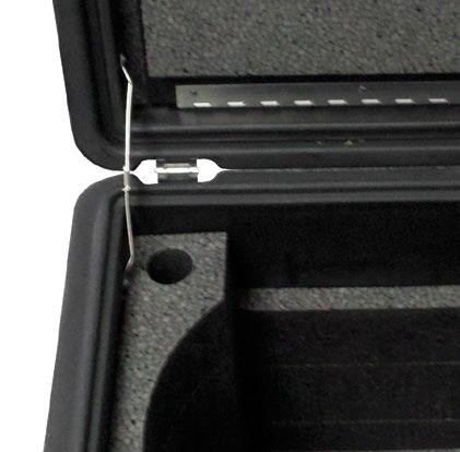
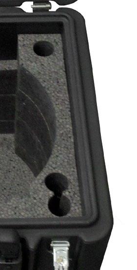
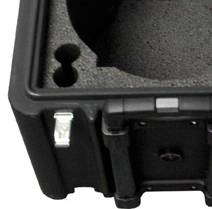
35 Part 6: Standardization of the SDG To assure that the SDG 200 s ability to make consistent measurements has not been compromised, a daily measurement should be taken on a reference material and tracked day to day for any unacceptable variations. A metallic plate has been installed in the bottom of the SDG 200 carrying case that is suitable for this purpose. Although this verification is referred to as a standardization of the gauge, the results of the standardization in no way influence the measurement of the gauge, they only serve to alert the user to a change in the way that the gauge is operating. Unexpected changes in the standardization values should be noted and discussed with Product Service at TransTech. Standardizations are performed inside the carry case. Located at the bottom of the case is a steel plate. Position the gauge on top of the plate inside the case. Be sure the gauge screen is facing you, if it is placed in the case backwards the handle will prevent proper seating you will get a false reading. The case should not be on top of or around (10ft.) any large metal objects. Turn the gauge ON and proceed to the Control Menu. Press Standardize, to obtain the above screen. Press Start, and do not touch the gauge while it is busy. The acceptable range for the A and B values are displayed on the screen, however, the gauge will respond with a PASS or Fail based on these ranges automatically. 35
36 Part 6: Standardization of the SDG If you receive a Fail, prior to calling the factory try the following: 1) Reposition the gauge/case to another location (outside preferably) 2) Be sure that you are testing the gauge inside the carry case that was provided with the SDG. The gauge and case are paired during production to determain the standardization. 3) Do not place the case on the back or near an automobile as well as any other large metal objects and/or wires 4) Be sure that no foreign objects have adhered to the bottom of the gauge or on the steel plate 5) Shut off all cell phones within 10ft of the gauge WARNING: THE STANDARDIZATION OF THE SDG 200 WILL ONLY WORK WITH THE PLATE IT HAS BEEN ISSUED TO. IF YOU RECEIVE A FAIL RESULT, CHECK TO BE SURE THE SERIAL NUMBERS LOCATED ON THE GAUGE AND THE STANDARDIZATION PLATE ARE THE SAME. WARNING: THE STANDARDIZATION OF THE SDG 200 MAY GIVE A FALSE FAIL IF TEST IS TAKEN TOO CLOSE TO METAL OBJECTS, POWER LINES OR OTHER ELECTRICAL DEVICES THAT MAY BE TOO CLOSE TO THE GAUGE. TURN THE GAUGE OFF AND MOVE THE GAUGE ATLEAST 10 FEET FROM THESE OBJECTS. IF AFTER THESE PRECAUTIONS ARE TAKEN THE GAUGE STILL DISPLAYS A FAIL CONTACT YOUR DISTRIBUTOR. Part 7: Explanation of Gradation and Compaction Reports All of the information needed to configure an SDG 200 to measure the density and moisture content of a material is available on Compaction Test Reports (Proctor Test) and Particle Size Distribution Reports (Gradation/Sieve Analysis) completed as outlined by ASTM D 422 and ASTM D In order to configure the gauge to operate on materials that have high clay and silt contents, results from an Atterberg limits test (ASTM D 4318) will be needed as well. 36
37 Part 7: Explanation of Gradation and Compaction Reports The thirteen properties that will need to be entered through the SDG s user interface are shown on the Material Details screen above and defined below. Further definitions of these properties can be found in Part 5 of the SDG Operators Handbook. Examples of a gradation report and compaction test are on the following pages. The Material ID is any identifier that can associate the material being evaluated with its test report. A report number or sample number should be entered here. For the example shown, is the Soil ID. Do not enter letters or characters as part of the Soil ID. The Description should be a used to describe the material and help make a visual association with the material being tested. Dark Brown Sand is used for this example. The Max Dry Density is the maximum practically achievable density a soil can have. This value is determined experimentally by performing a Proctor Test (ASTM D 1557) pounds per cubic foot is taken directly from the example compaction test report. The Optimum Moisture Content is the water content (%) at which the material can be compacted to its maximum dry density. This is determined experimentally by performing a Proctor Test (ASTM D 1557). 7.6% is taken directly from the example compaction test report. PL and LL are the plastic and liquid limits used to describe the plasticity of materials with a high silt and clay content. They are determined by following the test procedure outlined by ASTM D This example is a sandy material so PL and LL are input as 0.0. If plasticity tests had been performed on this material, the results would be given on the gradation report. Cu and Cc are the Coefficient of Uniformity and Coefficient of Curvature of the material. They are calculated values that are typically used describe the particle size distribution a soil. In this example, Cu = 4.4 and Cc = 0.94 % Gravel is the summation of the coarse and fine gravel in a sample of material. Some gradation test results will report this as a single value while others will break it down into the coarse and fine fractions. The SDG only recognizes the total percentage of gravel so the coarse and fine fractions will need to be added together before entering them. The gradation report shown breaks the gravel content out into Fine and Coarse fractions so those will need to be added together. 1.3% + 5.1% = 6.4% % Sand is the summation of the coarse, medium and fine sand in a sample of material. Some gradation test results will report this as a single value while others will break it down into the coarse, medium and fine fractions. The SDG only recognizes the total percentage of sand so the coarse, medium and fine fractions will need to be added together before entering them. The gradation report shown breaks the sand down into coarse, medium, and fine fractions, so the percent sand in the example shown is 8.1% % +48.2% = 87.6%. % Fines is the summation of the silt and clay in a sample of material. Some gradation test results will report this as a single value while others will break it down into the fractions of silt and clay. The SDG only recognizes the total percentage of fines so the coarse, silt and clay fractions will need to be added together before entering them. In this example, the percent fines is 6.0%. 37
38 Part 7: Explanation of Gradation and Compaction Reports % Greater than 3 inches is the percentage of the sample that is retained on the 3 inch sieve. Typical gradation tests report the percent finer or percentage that passes a particular sieve. In this example the percent finer for the 3 inch sieve is 100% so 0% of the sample is retained on the 3 inch sieve. % Greater than 3/4 inch is the percentage of the sample that is retained on the 3/4 inch sieve. Typical gradation tests report the percent finer or percentage that passes a particular sieve. In this example the percent finer for the 3/4 inch sieve is 98.7% so 1.3% of the sample is retained on the 3/4 inch sieve. 38
39 Part 7: Explanation of Gradation and Compaction Reports!! Note: The sum of %Greater the 3 inches, %Gravel, %Sand, and %Fines must add up to 100%. The default values programmed in the SDG software add up to 100%. As soon as one of those values is edited, the sum will no longer add up to 100% and an error message will be displayed until all of those gradation values are entered such that the sum is 100% again.!! 39
40 Appendix A: Using the SDG MTL Generator The SDG MTL Generator is a spreadsheet based application developed to determine the gradation inputs that the SDG needs to measure moisture and density of a soil in cases when the gradation performed was not done in accordance with ASTM D 422. The MTL Generator will allow users to input the gradation information that they have and will produce a particle size distribution curve from which the Cu, Cc, %Gravel, %Sand, %Fines, %>3/4 and %>3 values will be taken. Those values will be organized in a text file that can be uploaded onto the SDG via a USB flash drive. There are two MTL applications. One application allows users to input any sieve size, in millimeters, that was used in their gradation. The second application is useful when an ASTM D 422 type gradation report is available and users simply want to type the report summary into their PC and generate a text file to upload into the SDG. Getting Started: The MTL applications are Microsoft Excel spreadsheets that contain macros. For the applications to operate properly, Excel will need to be configured to run macros on any computer you wish to use these on. To change the macro settings on your computer, follow these steps. 1. Open up Excel 2. Select the Tools menu 3. Select the Macro option 4. Select the Security option 5. Select the Security Level Medium and select OK Once this setting is selected, Excel will ask you to confirm that you want to allow these applications to enable macros each time they are opened. Choose enable macros when prompted to do so. The Gradation Calculator has two separate screens. Screen one explains the use of the calculator, contains conversion tables for US customary and metric sieve sizes, contains the inputs for the sieve sizes and percent passing those sieves and has inputs for the material descriptors that make up the material definition file. 40
41 Appendix A: Using the SDG MTL Generator Screen One: Screen Two: The second screen of the MTL displays the plot of the particle size distribution curve and displays a table of all of the material properties that will be converted into a text file to upload to the SDG. On Screen 1, input the sieves used in the gradation (in mm) and the percent of material passing each sieve in columns A and B. The data must be entered in order of decreasing sieve sizes, and the first sieve entered should be of a size such that 100% of the material passed that sieve. 41

42 Appendix A: Using the SDG MTL Generator Screen Two: Once the gradation data is entered, fill in the rest of the material definition information in the yellow cells on Screen 1. The explanations and limitations for those definitions are explained on Screen 1. Clicking on the button to view the Particle size distribution curve displays Screen 2. The gradation curve will be visible, as well as a table of all of the properties that define the material. Clicking on the button to save and view the material properties file creates a text file with a.mtl extension of your PC s desktop. (Note: the first time you open a.mtl file on your PC, you will need to manually open it from the desktop with WordPad or similar text file editor. After that, your PC will always open.mtl files automatically.) The.mtl file can now be copied to a USB flash drive to be uploaded onto the SDG as explained on page 18. The SDG will only recognize the first 20.mtl files on the USB flash drive, and it will only recognize them if they are in the root directory of the flash drive. If.mtl files are in sub folders on your flash drive, the SDG will not recognize them. 42
Soil Density Gauge Operator s Handbook
 Soil Density Gauge Operator s Handbook 1 Table of Contents 2 Introduction 3 Measurement Technology 3 Application Summary 4 Safety 4 Operating Requirements 4 Controls & Components 5 Contents 5 Gauge Features
Application Brief TROXLER MODEL 3450
 Application Brief TROXLER MODEL 3450 Roadreader Plus Nuclear Moisture Density & Thin Layer Gauge May 2007 Introduction The Troxler Model 3450, Roadreader Plus, nuclear moisture / density gauge offers the
Moving money forward. CASSIDA TillTally + TillTally Elite Money Counting Scales
 Moving money forward CASSIDA TillTally + TillTally Elite Money Counting Scales Table of contents: 1. INTRODUCTION 1.1 About the Cassida TillTally 2 1.2 Box contents 2 1.3 Front and rear views 3 1.4 Display
MERRY GO ROUND ITEM NO: 8030
 MERRY GO ROUND ITEM NO: 8030 OWNER S MANUAL CAUTION: This unit is designed to be used safely by up to 4 children between the ages of 3 years to 8 years old with a maximum weight of 00 pounds (45.4 kgs)
Geotagger N3. User Manual (V1.0) Revised by Geosolve.be (Pol F. Gillard) with personal updates and help. Solmeta Technology Co.
 Revised by Geosolve.be (Pol F. Gillard) with personal updates and help. Solmeta Technology Co.") Geotagger N3 User Manual (V1.0) Revised by Geosolve.be (Pol F. Gillard) with personal updates and help Solmeta Technology Co., Ltd Copyright 2011 Solmeta Technology Co., Ltd. All Rights Reserved 1 Contents
Geotagger N3 User Manual (V1.0) Revised by Geosolve.be (Pol F. Gillard) with personal updates and help Solmeta Technology Co., Ltd Copyright 2011 Solmeta Technology Co., Ltd. All Rights Reserved 1 Contents
INSTRUCTION MANUAL INF Fax: (503)
") INSTRUCTION MANUAL INF151 1-800-547-5740 Fax: (503) 643-6322 www.ueiautomotive.com email: info@ueitest.com Introduction Congratulations on your purchase of the INF151 infrared thermometer. Like all UEi
INSTRUCTION MANUAL INF151 1-800-547-5740 Fax: (503) 643-6322 www.ueiautomotive.com email: info@ueitest.com Introduction Congratulations on your purchase of the INF151 infrared thermometer. Like all UEi
ENGLISH PORTUGUÊS NEDERLANDS DAB200
 DEUTSCH ENGLISH FRANÇAIS NEDERLANDS ESPAÑOL PORTUGUÊS NORSK DAB200 Contents Introduction..... 2 What is DAB + Digital Radio?.... 2 Setting up..... 3 Backlit display.... 4 Using headphones...... 4 Your
Jarvis standing desk. Assembly instructions. For assembly assistance, visit fully.com/howtojarvis or call or
 Jarvis standing desk Assembly instructions For assembly assistance, visit fully.com/howtojarvis or call 888-508-3725 or email support@fully.com Thank you for choosing a Jarvis desk from Fully. Cautions
USER MANUAL ENGLISH 1450 COIN COUNTER & SORTER
 USER MANUAL ENGLISH 1450 COIN COUNTER & SORTER INTRODUCTION ENGLISH Thank you for purchasing the Safescan 1450 coin counter and sorter. For proper use and maintenance, we advise to read this user manual
С 800 CASSIDA C 800 HIGH SPEED COIN COUNTER
 С 800 CASSIDA C 800 HIGH SPEED COIN COUNTER This manual contains important information on safety measures and operational features. Please read it carefully before operating your coin counter, and keep
CL900. True RMS 1000V 2000A 60MΩ ENGLISH. INSTRUCTION MANUAL 2000A Digital Clamp Meter. Measurement Technology
 ENGLISH INSTRUCTION MANUAL 2000A Digital Clamp Meter True RMS Measurement Technology NON-CONTACT VOLTAGE TESTING INRUSH CURRENT LOW IMPEDANCE DATA HOLD RANGE HOLD AUDIBLE CONTINUITY DIODE TEST CAPACITANCE
For more information:
 Verify Tab Click on the Verify tab to compare the measured and predicted max power values. Their ratio, in percent, is the Performance Factor. Solmetric PVA-600 PV Analyzer Quick Start Guide History Tab
USER MANUAL 600A AC Clamp Meter + NCV Model MA610
 USER MANUAL 600A AC Clamp Meter + NCV Model MA610 Additional User Manual Translations available at www.extech.com Introduction Thank you for selecting the Extech MA610 Clamp Meter. This meter measures
F400 QUICK-START GUIDE
 F400 QUICK-START GUIDE PLEASE READ THIS DOCUMENT BEFORE OPERATING YOUR PRINTER Revision 10-1/31/18 Page 1 Table of Contents 1. Introduction... 3 2. What s in the Box... 3 3. Unboxing Your F400... 4 4.
ULTRA-TRAC APL INSTRUCTION MANUAL. Read and understand instructions before use. Patented. 851 Transport Drive Valparaiso, IN
 ULTRA-TRAC APL A C O U S T I C P I P E L O C A T O R INSTRUCTION MANUAL Read and understand instructions before use. Patented MADE IN USA 851 Transport Drive Valparaiso, IN 46383-8432 Phone: 888 4SENSIT
NEO CAR AUDIO. Neo AUXiN AUX INPUT INTERFACE. Instruction Manual
 NEO CAR AUDIO Neo AUXiN AUX INPUT INTERFACE Instruction Manual IMPORTANT NOTE Neo AUXiN Dip switch positions MUST be set BEFORE any other step is taken. Otherwise, the kit will not operate properly. See
Walkie-Talkie. User Manual and Instruction. Getting Started
 Walkie-Talkie User Manual and Instruction Getting Started Installing the AA Batteries Your radio uses 3 AA Alkaline batteries. 1. With the back of the radio facing you, lift the battery latch up to release
A510S Operation Manual
 A510S Operation Manual REV 1.1 1 Table of Contents 1 General Information 1-1 Description 1-2 Potential Operational Hazards 1-3 Technical Specifications 1-4 Instrument Overview 1-5 Function Summary 2 How
KoPa Scanner. User's Manual A99. Ver 1.0. SHENZHEN OSTEC OPTO-ELECTRONIC TECHNOLOGY CO.,LTD.
 KoPa Scanner A99 User's Manual Ver 1.0 SHENZHEN OSTEC OPTO-ELECTRONIC TECHNOLOGY CO.,LTD. http://www.ostec.com.cn Content Chapter 1 Start... 1 1.1 Safety Warnings and Precautions... 1 1.2 Installation
CAST Application User Guide
 CAST Application User Guide for DX900+ Electromagnetic Multilog Sensor U.S. Patent No. 7,369,458. UK 2 414 077. Patents Pending 17-630-01-rev.b 05/24/17 1 Copyright 2017 Airmar Technology Corp. All rights
SwingTracker User Guide. Model: DKST02 User Guide
 SwingTracker User Guide Model: DKST02 User Guide PACKAGE CONTENTS What Comes in the Box USING YOUR SWINGTRACKER SENSOR Attach SwingTracker Sensor to your Bat Turn On your Sensor Pair your Sensor Remove
ET Water SmartWorks Panel Installation Guide
 ET Water SmartWorks Panel Installation Guide You are installing a new piece of equipment that retrofits into an existing irrigation controller in order to create a weather-based irrigation control system.
Heiland electronic GmbH TD / TD1 / TD2. B&W-Densitometers. USERS MANUAL Version 5
 Heiland electronic GmbH TD / TD1 / TD2 B&W-Densitometers USERS MANUAL Version 5 2 Table of Contents 1. GENERAL INFORMATION...4 2. SAFETY REGULATIONS...5 3. AREA OF APPLICATIONS...5 4. INSTRUMENT DESCRIPTION...6
Contents ... What is DAB + Digital Radio?... 2 Setting up... 3 Backlit display... 4 Using headphones... 4 Your radio Switch off...
 Contents Introduction... 2 What is DAB + Digital Radio?........... 2 Setting up........... 3 Backlit display.............. 4 Using headphones........... 4 Your radio... 5 Switch on........... 6 Telescopic
RISK OF SHOCK: DO NOT WIPE DOWN ANY ELECTRICAL COMPONENTS. ALWAYS KEEP AWAY FROM ALL AREAS WHERE ELECTRONIC COMPONENTS ARE INSTALLED.
 Maintenance General Cleaning Waste material from the printing process can accumulate inside the printer. Using a slightly damp, lint-free cloth, wipe the interior of the CubePro including the print plate,
LSC Radio User Guide Information and Guidelines
 LSC Radio User Guide Information and Guidelines The following user guide applies to both the Motorola VL50 and CLS1410 Radio s. Below are guidelines established for usage. 1) Radios and headsets are to
Smartphone RH/Temperature Probe Instruction Manual
 Smartphone RH/Temperature Probe 800014 Instruction Manual 1 TABLE OF CONTENTS Introduction...3 Features...4 App Screen...5 Measurement Procedures...7 Care and Maintenance...14 Compatibility...14 Specifications...15
DRO 100 REFERENCE MANUAL
 DRO 100 REFERENCE MANUAL Warranty ACU-RITE Products and accessories are warranted against defects in material and workmanship for a period of three years from the date of purchase. ACU-RITE will, at its
Nikon D7100 Camera Kit. -Checklist and Operations Manual-
 Airborne Digital Reconnaissance System (ADRS) Nikon D7100 Camera Kit -Checklist and Operations Manual- V4.2 October 21, 2014 National Headquarters, Civil Air Patrol 2 1.0 Equipment Pre-Mission Check 1.1
Advanced Test Equipment Rentals
 Established 1981 Advanced Test Equipment Rentals Solmetric PVA-600 PV Analyzer Quick Start Guide www.atecorp.com 800-404-ATEC (2832) : When using the wireless PVA Sensor Kit or manual sensors, the end
Qflash Pilot QF9. Shoe Mount Wireless Radio Commander for Qflash 5d-R and TRIO. F tested to comply with FCC standards. Operating Instructions
 F tested to comply with FCC standards CANADA : 3707AQFPILOT FCC ID: CEXQFPILOT Qflash PILOT This device complies with Part 15 of the FCC Rules and with RSS210 of Industry & Science Canada. Operation is
WARRANTY. Long Range Systems, LLC, 20 Canal St, Suite 4N, Franklin, NH 03235
 WARRANTY Long Range Systems, Inc. warrants the trap release product against any defects that are due to faulty material or workmanship for a one-year period after the original date of consumer purchase.
8000 SERIES PRECISION MULTIMETER VERIFICATION AND ADJUSTMENT GUIDE
 8000 SERIES PRECISION MULTIMETER VERIFICATION AND ADJUSTMENT GUIDE TRANSMILLE LTD. Version 1.1 : Apr 2015 TABLE OF CONTENTS PREPARING FOR CALIBRATION... 4 INTRODUCTION... 4 CALIBRATION INTERVAL SELECTION...
Micromate User Manual
 Microcoin Table of Contents Page Essential Information 2 1.0 Connection and Configuration 3 1.1 Connection 3 1.2 Switch On 4 1.3 Configuration for Use 4 2.0 Check the Configuration of a Validator 5 2.1
Operating Guide. HT25 Multi Side Tabber & Stamp Affixer. HASLER America s better choice. Mailing Systems And Solutions
 Operating Guide Mailing Systems And Solutions HASLER America s better choice HT25 Multi Side Tabber & Stamp Affixer An ISO 9001 Quality System Certified company Rev. 8/25/2010 Please record the following
Printing Humidity/Temperature Meter
 Printing Humidity/Temperature Meter INSTRUCTION MANUAL I. SAFETY INFORMATION Read the following safety information carefully before attempting to operate or service the meter. Use the meter only as specified
MicroLab 500-series Getting Started
 MicroLab 500-series Getting Started 2 Contents CHAPTER 1: Getting Started Connecting the Hardware....6 Installing the USB driver......6 Installing the Software.....8 Starting a new Experiment...8 CHAPTER
GE Sensing. Introduction. Wiring Diagrams (Typical) Field Calibration. Installing the Sensor
 Field Calibration. Installing the Sensor") clear mode enter clear mode enter GE Sensing Introduction The GE Telaire Vaporstat 900 sensor measures in applications in the range of 0 to 0 F dew point. The sensor package is designed for wall mounting.
clear mode enter clear mode enter GE Sensing Introduction The GE Telaire Vaporstat 900 sensor measures in applications in the range of 0 to 0 F dew point. The sensor package is designed for wall mounting.
Heritage Solar Lamp Post
 Heritage Solar Lamp Post Instruction Manual 23108 Thank you very much for choosing a Nature Power product! For future reference, please complete the owner s record below: Model: Purchase Date: Save the
DC155 Digital Visualizer. User Manual
 DC155 Digital Visualizer User Manual Table of Contents CHAPTER 1 PRECAUTIONS... 4 CHAPTER 2 PACKAGE CONTENT... 6 CHAPTER 3 PRODUCT OVERVIEW... 7 3.1 PRODUCT INTRODUCTION... 7 3.2 I/O CONNECTION... 8 3.3
Infrared Gun. Perfect For. Easy To Use. Features. Get Professional Results Every Time! Battery Installation. Model: IN1022
 Model: IN1022 Infrared Gun -76 to +1022 F/-60 to +550 C Perfect For Non-contact surface temperatures Easy To Use 1-second response Laser target illumination Backlit Data-hold One-button operation Features
Model OI-6940 Notis Quad 4-Gas Sensor Assembly
 Model OI-6940 Notis Quad 4-Gas Sensor Assembly Operation Manual Revision 2.3w Product Overview The Otis Instruments, Inc. Gen II WireFree OI-6940 Notis Quad is a battery-powered explosion-proof 4-gas sensor
Installation Manual REbus Beacon. Part of the Pika Energy Island M
 Installation Manual REbus Beacon Part of the Pika Energy Island M00020-01 REbus Beacon Serial Number: RCP Number: We are committed to quality and constant improvement. All specifications and descriptions
2400AT 4 I221 I221 1A 1A T T Rev. Rev B. C
 4 I2211AT Rev. Rev.B I2211AT C 2400AT Contents 1. Introduction 2. Components 3. Before operation 4. Setting up your Model 2400AT 4.1 setting the year 4.2 setting date 4.3 setting time 4.4 setting day line
WIRELESS 868 MHz TEMPERATURE STATION Instruction Manual
 WIRELESS 868 MHz TEMPERATURE STATION Instruction Manual INTRODUCTION: Congratulations on purchasing this compact 868MHz Temperature Station which displays radio controlled time, date, indoor and outdoor
3 CHANNEL LOAD CELL SIGNAL CONDITIONER. Owner's Manual
 3 CHANNEL LOAD CELL SIGNAL CONDITIONER Owner's Manual Boeing Helicopters Part Number 414ES230-SIG CON-1 Breeze-Eastern Part Number Y-1368-1 Onboard Systems Part Number 210-115-00 Manual Number 120-042-00
GFL-1000 User Manual Ground Fault Locator
 GFL-Series User Manual V1.1 GFL-1000 User Manual Ground Fault Locator Contents Contents... 1 1 Declaration of Conformity... 3 2 Introduction... 3 3 Equipment Information... 3 3.1 Safety Precautions...
Table of Contents. Instruction Manual - TORBAL DRX 5 Series
 Table of Contents Chapter 1.CAUTIONARY NOTES AND PRECAUTIONS... 3 Chapter 2.SPECIFICATIONS... 4 Chapter 3.Keys and display indicators... 5 Chapter 4.Parts Description... 6 Chapter 5.Unpacking the balance
RAZER GOLIATHUS CHROMA
 RAZER GOLIATHUS CHROMA MASTER GUIDE The Razer Goliathus Chroma soft gaming mouse mat is now Powered by Razer Chroma. Featuring multi-color lighting with inter-device color synchronization, the bestselling
9320 Manual Portable Battery Powered Indicator
 9320 Manual Portable Battery Powered Indicator Interface, Inc. 7401 E. Butherus Dr. Scottsdale, AZ 85260 800-947-5598 480-948-1924 (fax) www.interfaceforce.com CONTENTS INTRODUCTION...2 USER OPERATION...2
DM-46 Instruction Manual
 Auto Meter Products Inc. Test Equipment DM-46 Instruction Manual Automotive Multimeter and Inductive Amp Probe The DM-46 is the auto industry s answer to pocket portability in a 20 2650-1552-00 3/8/11
Installation & Operation Manual SAGA1-K Series Industrial Radio Remote Control
 Installation & Operation Manual SAGA1-K Series Industrial Radio Remote Control Gain Electronic Co. Ltd. Table Of Contents Safety Considerations ------------------------------------------------------------2
OPERATOR S INSTRUCTION MANUAL M-2625 AUTO RANGING DIGITAL MULTIMETER
 OPERATOR S INSTRUCTION MANUAL M-2625 AUTO RANGING DIGITAL MULTIMETER with Temperature Probe Copyright 2007 Elenco Electronics, Inc. Contents 1. Safety Information 3,4 2. Safety Symbols 5 3. Front Plate
UPLIFT 2-Leg Height Adjustable Standing Desk
 UPLIFT -Leg Height Adjustable Standing Desk Also watch our assembly video http://bit.ly/9ywwh DIRECTIONS FOR ASSEMBLY AND USE TABLE OF CONTENTS PAGE Safety and Warnings Usage Parts List Assembly Instructions
1: Introduction : Caution : Tips for Reading this Manual : Preface : System Highlights : Receiver
 1: Introduction....1 1 2: Caution.... 2 2 3: Tips for Reading this Manual....3 3 4: Preface....4 4 5: System Highlights....6 6 6: Receiver..7 7 6.1: Specifications......7 7 6.2: Receiver Operation... 7
IMPORTANT SAFEGUARDS READ AND FOLLOW ALL SAFETY INSTRUCTIONS SAVE THESE INSTRUCTIONS FOR FUTURE REFERENCE
 FSP-2X1 Digital High/Low Pir Fixture Integrated Sensor INSTALLATION INSTRUCTIONS IMPORTANT SAFEGUARDS When using electrical equipment, basic safety precautions should always be followed including the following:
USER MANUAL. Laser Distance Meter MODELS DT40M, DT60M, and DT100M
 USER MANUAL Laser Distance Meter MODELS DT40M, DT60M, and DT100M Contents Introduction... 3 Safety Instructions... 3 Descriptions... 4 Measurement Preparation... 6 Programming Menu... 8 Distance Measurements...
SMART TWEEZERS Model ST-1 User s Manual Version 1.0
 SMART TWEEZERS Model ST-1 User s Manual Version 1.0 Patent Pending TABLE OF CONTENTS Notice The contents of this document is believed to be accurate, but is not guaranteed by Excelta Corporation. The information
IRIS \ IRIS-I QUICK SET-UP GUIDE STEP 1 INSTALL
 IRIS \ IRIS-I QUICK SET-UP GUIDE STEP 1 INSTALL Confirm contents of package: 1 sensor, 1 cable, 1 wide lens (default), 1 narrow lens, mounting template, User s Guide. Install the sensor at the desired
By Dogtra Remote Controlled Dog Training Collars. Owner's Manual. Please read this manual thoroughly before operating the Dogtra EDGE training collar.
 By Dogtra Remote Controlled Dog Training Collars Owner's Manual Please read this manual thoroughly before operating the Dogtra EDGE training collar. Product Safety and Health Statement Intended Use They
Nikon Firmware Update for Coolpix 950 Version 1.3
 Nikon Firmware Update for Coolpix 950 Version 1.3 Notes: 1. It is most important that you follow the supplied directions; failure to follow all of the steps may result in your camera being disabled. 2.
MM700. INSTRUCTION MANUAL Auto-Ranging Digital Multimeter True RMS
 INSTRUCTION MANUAL Auto-Ranging Digital Multimeter True RMS Measurement Technology MM700 DATA & RANGE HOLD LOW IMPEDANCE AUDIBLE CONTINUITY MIN / MAX / RELATIVE TEMPERATURE DIODE TEST CAPACITANCE & FREQUENCY
Contents. Overview Introduction...3 Capabilities...3 Operating Instructions Installation...4 Settings... 5
 User s Manual Contents Overview................................................................. 3 Introduction..............................................................3 Capabilities...............................................................3
Laser Distance Finder Extech DT500
 User Guide Laser Distance Finder Extech DT500 Introduction Congratulations on your purchase of the Extech Model DT500 Laser Distance Finder. This meter measures Distance up to 70m (230 ) and calculates
Warehouse Instruction Guide
 Warehouse Instruction Guide Review Equipment & Supplies page 2 Set-Up Access Point page 6 Register Scanners page 8 Place Fixture Stickers/Enter Ranges page 10 Scanning Basics and Additional Keyboard Functions
ExpoM - ELF User Manual
 ExpoM - ELF User Manual Version 1.4 ExpoM - ELF User Manual Contents 1 Description... 4 2 Case and Interfaces... 4 2.1 Overview... 4 2.2 Multi-color LED... 5 3 Using ExpoM - ELF... 6 3.1 Starting a Measurement...
Installation Guide. Suitable for: OEM Integration OEM Installation Retro Fit Installation
 Installation Guide Suitable for: OEM Integration OEM Installation Retro Fit Installation DTI AngleBlaster release 1.1 DTI 2010 Overview Angleblaster Installation Guide A-1 To obtain the best accuracy from
RQflex 2. Manual English
 RQflex 2 Manual English Contents 1 Introduction 3 2 Description of the instrument 5 display, keys 6 technical data 8 3 Setting up the instrument 9 insertion of batteries 10 setting the time and date 11
SPS1M-EVK. SPS1M-EVK Battery Free Wireless Sensor Handheld Evaluation System EVAL BOARD USER S MANUAL
 SPS1M-EVK SPS1M-EVK Battery Free Wireless Sensor Handheld Evaluation System EVAL BOARD USER S MANUAL Introduction This guide describes how to use the Handheld Evaluation System to carry out sensor measurements
DC162 Digital Visualizer. User Manual. English - 1
 DC162 Digital Visualizer User Manual English - 1 Chapter 1 Precautions Always follow these safety instructions when setting up and using the Digital Visualizer: 1. Please do not tilt the machine while
AZATOM SONANCE T1 Digital Radio. DAB+/DAB/FM Radio Alarm Clock. User Manual. This manual is available to download online at
 AZATOM SONANCE T1 Digital Radio DAB+/DAB/FM Radio Alarm Clock User Manual This manual is available to download online at www.azatom.com Thank you for shopping with AZATOM Please read this manual carefully
MM700. True RMS ENGLISH. INSTRUCTION MANUAL Auto-Ranging. Measurement Technology
 INSTRUCTION MANUAL Auto-Ranging Digital Multimeter er True RMS Measurement Technology MM700 DATA & RANGE HOLD LOW IMPEDANCE AUDIBLE CONTINUITY MIN / MAX / RELATIVE TEMPERATURE DIODE TEST CAPACITANCE &
CashConcepts CCE 4000
 CashConcepts CCE 4000 Coin Counter and Sorting Machine User Manual Introduction Thank you for choosing the CCE 4000. This coin counting and coin sorting machine is designed to simplify the daily cash or
UPLIFT Height Adjustable Standing Desk 3-Leg (T-Frame) DIRECTIONS FOR ASSEMBLY AND USE
 DIRECTIONS FOR ASSEMBLY AND USE") UPLIFT Height Adjustable Standing Desk 3-Leg (T-Frame) DIRECTIONS FOR ASSEMBLY AND USE CAUTION MAKE SURE NO OBSTACLES ARE IN THE DESK S PATH AND ALL CORDS ARE OF APPROPRIATE LENGTH FOR DESK TRAVEL. FAILURE
UPLIFT Height Adjustable Standing Desk 3-Leg (T-Frame) DIRECTIONS FOR ASSEMBLY AND USE CAUTION MAKE SURE NO OBSTACLES ARE IN THE DESK S PATH AND ALL CORDS ARE OF APPROPRIATE LENGTH FOR DESK TRAVEL. FAILURE
LVTX-10 Series Ultrasonic Sensor Installation and Operation Guide
 LVTX-10 Series Ultrasonic Sensor Installation and Operation Guide M-5578/0516 M-5578/0516 Section TABLE OF CONTENTS 1 Introduction... 1 2 Quick Guide on Getting Started... 2 Mounting the LVTX-10 Series
PR200DAB DAB+/AM/FM RADIO USER MANUAL IMPORTANT! WARRANTY INFORMATION INSIDE. PLEASE READ. Trademark of TEAC Corporation JAPAN
 PR200DAB DAB+/AM/FM RADIO USER MANUAL IMPORTANT! WARRANTY INFORMATION INSIDE. PLEASE READ Trademark of TEAC Corporation JAPAN www.teac.com.au WARRANTY PROCEDURE v1.7b: July 2016 for 12M Replacement Please
DM-46 Instruction Manual
 Test Equipment Auto Meter Products Inc. 413 West Elm Street Sycamore, IL 60178 Service (815) 899-0801 Toll Free (866) 883-TEST (8378) www.autometer.com/test DM-46 Instruction Manual Automotive Multimeter
DRO 200T REFERENCE MANUAL
 DRO 200T REFERENCE MANUAL Readout Parameter Access Code An access code must be entered before machine-related parameters can be set or changed. This prevents inadvertent adjustments to the setup parameters.
Table of Contents. Polytel GMA Glucose Meter Accessory for Bayer Ascensia Contour Model PWR USER MANUAL Version: B
 Table of Contents Polytel GMA Glucose Meter Accessory for Bayer Ascensia Contour Model PWR-08-07 USER MANUAL Version: B Polymap Wireless 310 S. Williams Blvd. Ste. 350 Tucson, Arizona 85711 (520) 747-1811
VMS-4000 Digital Seismograph System - Reference Manual
 VMS-4000 Digital Seismograph System - Reference Manual This equipment should be installed, maintained and operated by technically qualified personnel. Any errors or omissions in data or it s interpretations,
Important safety instructions
 MMR-88 Version 1 Important safety instructions 1. 2. 3. 4. 5. 6. 7. 8. 9. Please read these instructions carefully. Please keep these instructions for future reference. Heed all warnings Follow all instructions
Dawson DSM150. Digital Light Meter User s Manual
 Dawson DSM150 Digital Light Meter User s Manual TABLE OF CONTENTS LIMITED WARRANTY AND LIMITATION OF LIABILITY... 3 Out of Box... Error! Bookmark not defined. Accessories... 4 Safety Information... 6 Certification...
EchoSonic II Ultrasonic Level Transmitter LU23, LU28 & LU29 Series Quick Start NEMA 4X Enclosure
 EchoSonic II Ultrasonic Level Transmitter LU23, LU28 & LU29 Series Quick Start NEMA 4X Enclosure QS300480 Rev B 2013 Flowline, Inc. All Rights Reserved Made in USA 10500 Humbolt Street, Los Alamitos, CA
English. Money Counter. Coin and banknote counter. DEUTsCH. Manual
 ITALIANO ESPAÑOL FRANçAIS NEDERLANDS English Money Counter DEUTsCH Coin and banknote counter Manual Money Counter for Coins and Banknotes Introduction Thank you for choosing the Money Counter series. The
Pressure Field Unit User Guide
 Rev. 0605 Pressure Field Unit User Guide A Division of Adaptive Instruments Corp. 577 Main Street Hudson, MA 01749 U.S.A. TEL: 800-879-6576 978-568-0500 FAX: 978-568-9085 Email: support@accutechinstruments.com
ONYX Deskset HD. Portable Video Magnifier User s Guide. Freedom Scientific, Inc Revision A
 ONYX Deskset HD Portable Video Magnifier User s Guide Freedom Scientific, Inc. www.freedomscientific.com 440829-001 Revision A PUBLISHED BY Freedom Scientific 11800 31 st Court North St. Petersburg, Florida
Table of Contents. Polytel GMA Glucose Meter Accessory for Abbott FreeStyle Lite and FreeStyle Freedom Lite Model PWR USER MANUAL Version: B
 Table of Contents Polytel GMA Glucose Meter Accessory for Abbott FreeStyle Lite and FreeStyle Freedom Lite Model PWR-08-09 USER MANUAL Version: B Polymap Wireless 310 S. Williams Blvd. Ste. 350 Tucson,
Driveway Alarm INSTALLATION MANUAL
 WIRELESS ACCESS CONTROLS Driveway Alarm INSTALLATION MANUAL Mounting post Transmitter Receiver Transformer Sensor Kit Includes: Transmitter Module Sensor Receiver Transformer Mounting post (3 pieces) Installation
IG-2500 OPERATIONS GROUND CONTROL Updated Wednesday, October 02, 2002
 IG-2500 OPERATIONS GROUND CONTROL Updated Wednesday, October 02, 2002 CONVENTIONS USED IN THIS GUIDE These safety alert symbols are used to alert about hazards or hazardous situations that can result in
impact VC-500LR Monolight INSTRUCTIONS
 impact lighting equipment and accessories VC-500LR Monolight INSTRUCTIONS Congratulations on your purchase of the Impact VC-500LR Monolight. We feel that it will contribute much to your photographic skill
Table of Contents. Polytel GMA Glucose Meter Accessory Model PWR USER MANUAL Version: 2
 Table of Contents Polytel GMA Glucose Meter Accessory Model PWR-08-03 USER MANUAL Version: 2 Polymap Wireless 310 S. Williams Blvd. Ste. 346 Tucson, Arizona 85711 (520) 747-1811 www.polymapwireless.com
NEULOG PHOTO GATE LOGGER SENSOR GUIDE
 NeuLog photo gate logger sensor NUL-209 Part# NL-2090 The NeuLog photo gate sensor can be used for any science experiment which involves taking accurate velocity and/or acceleration measurements especially
NEULOG PHOTO GATE LOGGER SENSOR GUIDE
 NeuLog photo gate logger sensor NUL-209 The NeuLog photo gate sensor can be used for any science experiment which involves taking accurate velocity and/or acceleration measurements especially in the field
WS-7136U Wireless 433 MHz Temperature Station. Instruction Manual
 WS-7136U Wireless 433 MHz Temperature Station Instruction Manual TABLE OF CONTENTS Topic Page Inventory of Contents 3 Additional Equipment 4 Quick Setup 5-9 Detailed Setup Guide Battery Installation 10-12
MM V 10A ENGLISH. INSTRUCTION MANUAL Auto-Ranging DATA HOLD AUDIBLE CONTINUITY MIN / MAX TEMPERATURE DIODE TEST CAPACITANCE
 INSTRUCTION MANUAL Auto-Ranging Digital Multimeter MM400 DATA HOLD AUDIBLE CONTINUITY MIN / MAX TEMPERATURE DIODE TEST CAPACITANCE 600V 10A 40MΩ 2 GENERAL SPECIFICATIONS Klein Tools MM400 is an auto-ranging
FAG PRESTO DX. FAG PRESTO-DX preliminary User Manual. FAG GRAPHIC SYSTEMS S.A. 3, rue de la Vigie CH-1003 Lausanne Switzerland
 FAG PRESTO DX FAG PRESTO-DX preliminary User Manual Table of Contents Safety Instructions... 4 DECLARATION OF CONFORMITY... Erreur! Signet non défini. PRESTO DX... 5 Pass Fail Indicator... 6 RESET and
reference guide reference guide reference guide
 hp photosmart 240 series reference guide reference guide reference guide contents 1 welcome..................................... 1 find more information.............................. 1 what s in the box.................................
INTRODUCTION. Bills (loose) Coins (loose, rolled) Using the Cashmaster you will notice some changes in the way you work:
 Coins (loose, rolled) Using the Cashmaster you will notice some changes in the way you work:") User Manual CONTENTS Introduction.............. 1 Box items and guidelines... 2 Charging.. 2 Unpacking... 3 Warning...... 3 The main parts of the Cashmaster... 4 Keys and display The keypad......... 5
User Manual CONTENTS Introduction.............. 1 Box items and guidelines... 2 Charging.. 2 Unpacking... 3 Warning...... 3 The main parts of the Cashmaster... 4 Keys and display The keypad......... 5
MANUAL. Textron Motors Diagnostic Tool. This manual is valid for the following Textron Motors Diagnostic Tool:
 MANUAL Textron Motors Diagnostic Tool This manual is valid for the following Textron Motors Diagnostic Tool: 0507 TD0507_HB Rev F 6..05 en_english Read the manual before performing the task on the engine.
TYPE - K.J.E.T. PRINTING THERMOMETER. Model INSTRUCTION MANUAL
 TYPE - K.J.E.T. PRINTING THERMOMETER Model 422324 INSTRUCTION MANUAL CONTENTS Title Page I. SAFETY INFORMATION... 1 II. SPECIFICATIONS... 2 2-1 General Information...2 2-2 Electrical Specifications...4