Digital Radiography System. user's manual _11
|
|
|
- Jennifer Logan
- 5 years ago
- Views:
Transcription

1 EN Digital Radiography System user's manual _11
2
3 TABLE OF CONTENTS 1 INTRODUCTION SYMBOLS RELATED MANUALS SAFETY PRECAUTIONS SYSTEM REQUIREMENTS PLANMECA PROSENSOR CONTROLBOX INDICATOR LIGHT BEFORE EXPOSURE Positioning the patient Positioning the sensor Selecting exposure values CAPTURING INTRAORAL IMAGES Capturing single intraoral images Capturing images into a study template IMAGE QUALITY CONTROL Quality check using SMPTE test pattern USING THE SENSOR HOLDERS CLEANING Surfaces Sensors and cables Sensor holders Planmeca ProSensor ControlBox DISPOSAL OF PLANMECA PROSENSOR TECHNICAL SPECIFICATIONS...18 APPENDIX A: EXPOSURE VALUES FOR PLANMECA PROX...20 A.1 Default exposure values A.2 Preprogrammed settings values User s Manual Planmeca ProSensor 1
4 TABLE OF CONTENTS The manufacturer, assembler, and importer are responsible for the safety, reliability and performance of the unit only if: - installation, calibration, modification and repairs are carried out by qualified authorized personnel - electrical installations are carried out according to the appropriate requirements such as IEC equipment is used according to the operating instructions Planmeca pursues a policy of continual product development. Although every effort is made to produce up-to-date product documentation this publication should not be regarded as an infallible guide to current specifications. We reserve the right to make changes without prior notice. COPYRIGHT PLANMECA Publication number Revision 11 Released 21 November Planmeca ProSensor User s Manual
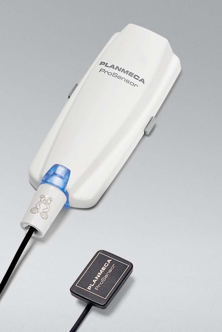
5 INTRODUCTION 1 INTRODUCTION This manual describes how to use and install the Planmeca ProSensor sensor that is intended to be used for capturing digital intraoral x-ray images from patient s jaw, teeth, gums, roots and root canals by trained dental care professionals. Please read this manual carefully before using the system. Planmeca ProSensor automatically triggers and captures images to the start and end of the x-ray radiation so that any intraoral x-ray unit supporting exposure times and cones listed in tables of chapter Exposure values for Planmeca ProSensor can be used. The Planmeca Romexis imaging software or third party software stating compatibility with Planmeca ProSensor or software stating compatibility through TWAIN can be used for image capturing. Planmeca ProSensor is connected to a computer using Ethernet or USB interface and it supports Windows and MAC operating systems, see details in section TECHNICAL SPECIFICATIONS on page 18. This manual is valid for following software revisions: Planmeca ProSensor Ethernet software version R or later Planmeca ProSensor USB software version R or later Didapi software version 4.8.1or later. User s Manual Planmeca ProSensor 1


6 SYMBOLS 2 SYMBOLS Type BF equipment (Standard IEC ). Attention, consult accompanying documents (Standard IEC ). The use of accessory equipment not complying with the equivalent requirements of this equipment may lead to a reduced level of safety of the resulting system. Consideration relating to the choice shall include: use of the accessory in the Patient Vicinity evidence that the safety certification of the accessory has been performed in accordance to appropriate IEC60601 and/or IEC harmonized national standard. ETL CLASSIFIED Planmeca ProSensor is ETL classified and conforms to ANSI/AAMI ES and is certified to CAN/CSA C22.2 No : Separate collection for electrical and electronic equipment according to Directive 2002/96/EC (WEEE) 3 RELATED MANUALS This manual should be used in conjunction with following manuals: Planmeca ProX User s manual ( ) Planmeca Romexis User s manual ( ) 2 Planmeca ProSensor User s Manual
7 SAFETY PRECAUTIONS 4 SAFETY PRECAUTIONS The system should be operated by qualified personnel only. EMC requirements have to be considered, and the equipment must be installed and put into service according to the specific EMC information provided in the accompanying documents. CAUTION Handle the Planmeca ProSensor according to the instructions given in this manual. Do not pinch the sensor or the cable. Do not to drop the sensor or pull strongly the sensor cable. Never cut, nick or sharply bend the sensor cable. Always advise the patient not to bite the sensor or the cable. The Planmeca limited warranty does not cover damage which is due to misuse, e.g. dropping the sensor, neglect, or any cause other than ordinary application. CAUTION Do not let the sensor cable run along the floor. Protect the cable from rolling over it with a chair or walking over it. CAUTION Do not store or use the Planmeca Sensor near (3m or 10 ft) an electrosurgical knife. CAUTION Do not unnecessarily touch the connector pins to keep them clean. User s Manual Planmeca ProSensor 3
8 SYSTEM REQUIREMENTS 5 SYSTEM REQUIREMENTS The PC and other equipment connected to the system must be: approved by local authorities: e.g. IEC-approved (CE marked), UL / CSA approved located outside the patient area (more than 2m (79 in.) from the X-ray unit) protectively earthed. The connection of additional equipment to a multiple portable socket-outlet must only be possible by using a tool or be supplied via separating transformer. The multiple portable socket-outlets shall not be placed on the floor. Make sure that the system is protected with fire wall and up-to-date anti-virus software. If possible, isolate the system from office network. For latest up-to-date system requirements see also Planmeca website > Software > System requirements Table 1. Planmeca Romexis system requirements Planmeca Romexis client work station Planmeca Romexis database server Processor Intel Core 2 Duo 2 GHz or better Intel Core 2 Duo 3GHz or better RAM 3 GB 3 GB minimum Hard disk space 80 GB 2 x 500 GB (RAID/mirroring) Graphics card Any integrated or dedicated Any USB port USB port 2.0 USB port 2.0 Monitor 1280 x x 1024 Peripherals CD-ROM drive CD-ROM drive Backup medium None necessary DAT or equivalent Operating system Windows XP Pro (32 bit) Windows Vista Pro (32 or 64 bit) Windows 7 Pro (32 or 64 bit) Windows 8 Pro (32 or 64 bit) Mac OS X (Intel)* Windows XP Pro (32 bit) Windows 2003 Server (32 or 64) Windows 2008 Server (32 or 64) Windows Vista Pro (32 or 64) Windows 7 Pro (32 or 64) Windows 8 Pro (32 or 64) Mac OS X (Intel) Other Java platform (Java Virtual Machine 1.6) Java platform (Java Virtual Machine 1.6) 4 Planmeca ProSensor User s Manual
9 PLANMECA PROSENSOR CONTROLBOX INDICATOR LIGHT 6 PLANMECA PROSENSOR CONTROLBOX INDICATOR LIGHT Planmeca ProSensor indicator light control_box_2.eps Table 2. Planmeca ProSensor ControlBox indicator light explanation CONTROLBOX INDICATOR LIGHT Off Dim blue Bright blue Slowly flashing blue PLANMECA PROSENSOR STATUS Planmeca ProSensor system power off Planmeca ProSensor system is off (not in intraoral exposure-mode and the cable is connected to the ControlBox) Planmeca ProSensor system is on (Imaging program communicates with the Planmeca ProSensor system) Waiting for Ready Steady green Rapidly flashing green Steady red Slowly flashing yellow Slowly flashing blue, turns to slowly flashing dim blue, then to quickly flashing dim blue Flashing violet Waiting for Exposure The exposure is taken and image is transferred from the sensor to the ControlBox Error mode Service mode Uploading ControlBox software Reading calibration files from the sensor. ControlBox startup with back-up software The exposure can only be taken when the Planmeca ProSensor ControlBox indicator light is green and steady, not when the indicator light is flashing. User s Manual Planmeca ProSensor 5
10 BEFORE EXPOSURE 7 BEFORE EXPOSURE Detailed instructions for using Planmeca ProX X-ray unit and Planmeca Romexis software are given in their User s manual, which should be used in conjunction with this manual. It is recommended to use a sensor holder. Select the correct sensor holder according to the type of exposure, refer to the sensor holder manual supplied with the sensor holder package. In case the environment temperature reaches 40 C the sensor surface warms up to its maximum temperature of 49 C and may feel warm. The surface temperature of the sensor cools off when in patient contact. 7.1 Positioning the patient Ask the patient to sit down. Place a protective lead apron over the patient s chest. 7.2 Positioning the sensor When using the sensor for the first time the message Loading calibration files will appear on the Romexis window. When connecting the same sensor to another workstation the calibration files will be reloaded. Select the appropriate sensor and connect it to the Planmeca ProSensor ControlBox. Paralleling technique (recommended) The sensor is placed to a sensor holder which is used to align the sensor parallel to the long axis of the tooth. Use a long cone for the paralleling technique. Long axis of the tooth Sensor 6 Planmeca ProSensor User s Manual
11 BEFORE EXPOSURE Bisecting angle technique (optional) The patient holds the sensor in place with his finger. The X-ray beam is directed perpendicularly towards an imaginary line which bisects the angle between the film plane and the long axis of the tooth. Sensor Long axis of the tooth The use of the plastic cover is not necessary because the sensor can be sterilized with liquid. The sterilization must be done after each patient. Be very careful not to put excessive pressure on the sensor. Do not place a clamp on the sensor. Do not take occlusal exposures with the sensor, and advise the user not to bite the sensor. Never clamp the sensor package or cable with a hemostat or an unmodified Snap-a-ray holder. Make sure the Planmeca ProSensor system is ready for the exposure and communicates with Romexis (refer to section 6 PLANMECA PROSENSOR CONTROLBOX INDICATOR LIGHT on page 5. On how to place the sensor into the patient s mouth refer to the sensor holder manual supplied with Planmeca ProSensor. User s Manual Planmeca ProSensor 7
12 BEFORE EXPOSURE 7.3 Selecting exposure values Select the digital imaging mode of the unit or adjust the exposure time according to the table. In the digital imaging mode the highest time value that can be selected is 0.80 seconds. Table 3. Exposure values for Planmeca ProSensor sensors with 20 cm (8 ) cones TIME 70 kv/ 66 kv/ 63 kv/ 60 kv/ 57 kv/ 55 kv/ 52 kv/ 50 kv/ 70 kv/ 66 kv/ 63 kv/ 60 kv/ 57 kv/ 55 kv/ 52 kv/ 50 kv/ 0.01s 0.02s 0.03s 0.04s 0.05s 0.06s 0.08s 0.10s 0.12s 0.16s 0.20s 0.25s 0.32s 0.40s 0.50s 0.64s 0.80s I INCISORS P PREMOLARS AND CANINES M MOLARS 8 Planmeca ProSensor User s Manual
13 BEFORE EXPOSURE Table 4. Exposure values for Planmeca ProSensor sensors with 30 cm (12 ) cones TIME 0.01s 0.02s 0.03s 0.04s 0.05s 0.06s 0.08s 0.10s 0.12s 0.16s 0.20s 0.25s 0.32s 0.40s 0.50s 0.64s 0.80s 70 kv/ 66 kv/ 63 kv/ 60 kv/ 57 kv/ 55 kv/ 52 kv/ 50 kv/ 70 kv/ 66 kv/ 63 kv/ 60 kv/ 57 kv/ 55 kv/ 52 kv/ 50 kv/ maxilla I P M mandible I P M maxilla I P M mandible I P M I INCISORS P PREMOLARS AND CANINES M MOLARS User s Manual Planmeca ProSensor 9

14 CAPTURING INTRAORAL IMAGES 8 CAPTURING INTRAORAL IMAGES When connecting the sensor for the first time the message Loading calibration files will appear on the Romexis window. Also if you connect the same sensor to another workstation the files will be loaded again. 8.1 Capturing single intraoral images 1. Click the Intraoral Exposure button on the upper toolbar to initiate the intraoral image capture mode. 2. The Intraoral Exposure window appears. 3. When the X-ray unit is in ready state a message Waiting for Ready appears on top of the window. 4. Prepare the patient for exposure, select exposure parameters and position Planmeca ProX as required, for more information refer to Planmeca ProX user s manual. Inform the patient that the sensor may feel warm in the mouth. 10 Planmeca ProSensor User s Manual
15 CAPTURING INTRAORAL IMAGES When the Planmeca ProSensor system is ready for exposure the message Waiting for Exposure appears on top of the window. 5. Take an exposure as usual. After the exposure a message stating Saving the image appears on the display and the image is automatically stored into the database. 6. Define the tooth numbers and sensor orientation and take the next exposure, or click Done to return to the Imaging module when all exposures have been captured. Remove the sensor from patient s mouth when all exposures have been taken. User s Manual Planmeca ProSensor 11


16 CAPTURING INTRAORAL IMAGES 8.2 Capturing images into a study template The images are captured into study templates containing a predefined set of multiple images. To capture intraoral images into a study template click this button. 1. Select the desired study template from the list. At the beginning of the list there are empty templates and at the bottom of the list there are studies with dates that already include images captured earlier. While capturing images using a template, Planmeca Romexis navigates through the template in a predefined order, denoting the current image to be captured by a blue border around the slot. 2. Follow the tooth numbering and sensor orientation as shown on the image and predefined in the template. 3. Prepare the patient for exposure, select exposure parameters and position Planmeca ProX as required, for more information refer to Planmeca ProX user s manual. 12 Planmeca ProSensor User s Manual
17 CAPTURING INTRAORAL IMAGES Inform the patient that the sensor may feel warm in the mouth. When the Planmeca ProSensor system is ready for exposure the message Waiting for Exposure appears on top of the window. You can now expose the X-ray as usual. After the exposure a message stating Saving the image appears on the display and the image is automatically stored into the database. To cancel the process click Cancel. The captured images are saved and the incomplete study is preserved for later use. 4. Once all images have been captured click Done. Remove the sensor from patient s mouth when all exposures have been taken. User s Manual Planmeca ProSensor 13
18 IMAGE QUALITY CONTROL 9 IMAGE QUALITY CONTROL Verify the image quality after installing the software and before patient exposure. Perform quality control check according to the requirements of local authorities, using for example Quart phantom or similar. It is recommended to regularly monitor the image quality using the same phantom according to the requirements of local authorities. See also the Constancy test manual for Planmeca Digital Intraoral X-ray System (publication number ) Before performing phantom exposures verify that the brightness and contrast settings of the monitor are accurate by using a SMPTE test pattern or similar. 9.1 Quality check using SMPTE test pattern The test image is specified by the Society of Motion Picture and Television Engineers ( and follows the SMPTE Recommended Practise RP Specifications for Medical Diagnostic Imaging Test Pattern for Television Monitors and Hard-Copy Recording Cameras. This image should be used for monitor setting and quality checks performed: Before every working day: The 5% gray field inside the 0% field and the 95% gray field inside the 100% field should be visible. If not, adjust the brightness and contrast of the monitor. Every month: The line raster in the corners and in the centre must be visible, the vertical and horizontal lines must form undistorted squares and the homogeneous grey background must not be coloured. 10 USING THE SENSOR HOLDERS The sensor holders provide an easy way to position the sensor for different anatomical and diagnostic needs. For instructions how to use the sensor holders, please refer to the manual supplied with the sensor holder package. 14 Planmeca ProSensor User s Manual
19 CLEANING 11 CLEANING Before cleaning the system, always check that the X- ray unit and the Planmeca ProSensor system are off (Planmeca ProSensor ControlBox indicator light is off) Surfaces The surfaces can be cleaned with a soft cloth damped in a mild cleaning solution. Stronger cleaning agents can be used for disinfecting the surfaces. We recommend Dürr System-hygiene FD 333 or respective disinfecting solution Sensors and cables Planmeca ProSensor sensors allow enhanced infection control in the surgery. As the sensor casing is hermetically sealed the sensors can be immersed in disinfectant solution. Always use appropriate instruments for cleaning the sensors. It is mandatory to carefully follow the disinfecting and cleaning recommendations in order to not damage the sensors. CAUTION The sensors cannot be sterilized in autoclave or UV oven. Wipe up the sensor surface with a soft cloth damped into a disinfectant solution. The sensors can be soaked in a disinfection solution as long as there are no nicks in the cable. The recommendable disinfectant solutions are Dürr System Hygiene FD 322 or FD 333 or similar product. The immersion time with the Dürr disinfectants is 2 minutes. If more effective disinfection or cold sterilization is preferred for cleaning, we recommend the Johnson&Johnson Cidex Opa high level disinfectant at a minimum temperature of 20 C with maximum immersion time of 8 minutes for a reuse period not to exceed 14 days. Follow carefully the manufacturer s recommendations on immersion time and recommended disinfectant liquids. User s Manual Planmeca ProSensor 15
20 CLEANING Do not leave the sensor in the disinfection solution overnight. The magnetic connector of the sensor cable should not be soaked. Use a new disposable protection cap for every sensor usage. Wipe up the sensor surface with a compress moisten into a sterile solution. The sensor connector can be cleaned using a soft cloth Sensor holders For cleaning the sensor holders refer to the manual supplied with the sensor holder package Planmeca ProSensor ControlBox The ControlBox can be cleaned with a soft cloth damped in a mild cleaning solution. CAUTION Switch off the unit before cleaning. Do not disinfect the unit. 16 Planmeca ProSensor User s Manual
21 12 DISPOSAL OF PLANMECA PROSENSOR DISPOSAL OF PLANMECA PROSENSOR In order to reduce the environmental load over the product s entire lifecycle, PLANMECA s products are designed to be as safe as possible to manufacture, use and dispose of. Parts which can be recycled should always be taken to the appropriate processing centres, after hazardous waste has been removed. Disposal of obsolete systems is the responsibility of the waste possessor. All parts and components containing hazardous materials must be disposed of in accordance with waste legislation and instructions issued by the environmental authorities. The risks involved and the necessary precautions must be taken into account when handling waste products. Part Main materials for disposal Recyclable material Waste disposal site Hazardous waste (separate collection) ControlBox - metal stainless steel ASA + PC X X - plastic POM X PC X PU X Cables copper X TPE/PU X Packing cardboard, paper, PE foam X X X Sensors Return the sensors to Planmeca. Other parts PoE X If the component boards cannot be recycled handle them as electronic scrap, i.e. according to the local legislation. User s Manual Planmeca ProSensor 17
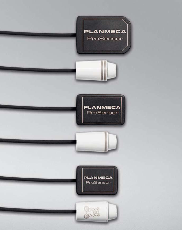
22 TECHNICAL SPECIFICATIONS 13 TECHNICAL SPECIFICATIONS Sensors Sensor type CMOS with scintillator Sensor dimensions Size 0 overall 33.6 x 23.4 mm (1.33 x 0.92 in.) active area 25.5 x 18.9 mm (1,00 x 0,74 in.) number of pixels 850 x 629 view delay <5 sec. Size 1 overall 39.7 x (1.56 x 0.99 in.) active area 31.5 x 20.7 (1.24 x 0.81 in.) number of pixels 1050 x 690 view delay <5 sec. Size 2 overall 44.1 x 30.4 mm (1,74 x 1.2 in.) active area 36 x 26.1 mm (1,74 x 1,2 in.) number of pixels 1200 x 870 view delay <5 sec. Resolution Theoretical resolution Cable length Expected service life 17 lp/mm 33 lp/mm 0.86 m (33.9 in.) or 2.0 m (78.7 in.) 10 years / exposure cycles Supported operating systems Client Server Windows XP Pro (32 bit) Windows XP Pro (32 bit) Windows Vista Pro (32 or 64) Windows 2003 Server (32 or 64) Windows 7 Pro (32 or 64) Windows 2008 Server (32 or 64) Windows 8 Pro (32 or 64) Windows Vista Pro (32 or 64) Mac OS X (Intel)* Windows 7 Pro (32 or 64) Windows 8 Pro (32 or 64) Mac OS X (Intel) 18 Planmeca ProSensor User s Manual
23 TECHNICAL SPECIFICATIONS Ethernet ControlBox Dimensions Power supply 112 x 46 x 24 mm (4.41 x 1.81 x 0.94 in.) 48 V DC 65 ma Cables ControlBox to PoE PoE to LAN Power supply RJ45 10m OR 15m RJ45 10m OR 15m Phihong Single Port Injector Type: PSA16U-480 (POE) Input voltage VAC (50-60 Hz) Output voltage 48VDC Max. output current 0.35 A Insulation voltage Primary-secondary 3000VDC USB ControlBox Dimensions Cables Power supply 112 x 46 x 24 mm (4.41 x 1.81 x 0.94 in.) fixed USB 2.0 power supply cable 2 or 5m (6.6 or 16.4 ft) Input power 2 W Operating environment Planmeca ProSensor is for indoor use only. The equipment is installed on the wall or on/under the table. The user moves the sensor into the operation position by hand. The room and operation must comply with the x-ray safety shielding requirements according to radiation safety regulation in the country. The system is used by dental care professionals. Prior to installation of the system check that the local conditions are compatible with the appliance design. The temperature of the operating environment should be between + 15 C and + 40 C. The relative humidity of the operating environment should not exceed 60%. Atmospheric pressure range should be between 700 hpa hpa. Transportation and storage environment Transportation and storage temperature -10 C C. The relative humidity during transportation and storage should not exceed 95%. User s Manual Planmeca ProSensor 19
24 TECHNICAL SPECIFICATIONS APPENDIX A: EXPOSURE VALUES FOR PLANMECA PROX The recommended exposure values are given in Planmeca ProX User s manual section 17 EXPOSURE VALUE TABLES. A.1 Default exposure values When the unit is switched on, the default exposure values appear on the displays. Short cone exposure values PATIENT kv ma time Adult Child Long cone exposure values PATIENT kv ma time Adult Child For programming these values see the Planmeca ProX User s manual section 16.1 Programming default exposure values 20 Planmeca ProSensor User s Manual
25 TECHNICAL SPECIFICATIONS A.2 Preprogrammed settings values For programming these values see the Planmeca ProX User s manual, section 16.3 Programming the preprogrammed settings. Two sets of exposure values (time/kv/ma) have been programmed for each exposure region: one for mode and one for mode. INCISORS PREMOLARS AND CANINES MOLARS kv ma time kv ma time kv ma time Adult Child Maxilla Mandible Maxilla Mandible OCCLUSAL EXPOSURE ENDODONTIC BITE-WING kv ma time kv ma time kv ma time Adult Child Maxilla Mandible Maxilla Mandible User s Manual Planmeca ProSensor 21
26 TECHNICAL SPECIFICATIONS When using the 30 cm long cone program see Planmeca ProX User s manual section 17 EXPOSURE VALUE TABLES or select three steps darker density (longer exposure time). INCISORS PREMOLARS AND CANINES MOLARS kv ma time kv ma time kv ma time Adult Child Maxilla Mandible Maxilla Mandible OCCLUSAL EXPOSURE ENDODONTIC BITE-WING kv ma time kv ma time kv ma time Adult Child Maxilla Mandible Maxilla Mandible Planmeca ProSensor User s Manual
27
28 Planmeca Oy Asentajankatu Helsinki Finland tel fax sales@planmeca.com
1 PLANMECA ProSensor. ProSensor Digital Intraoral Systems
 PLANMECA 10-YEAR Warranty Program Digital Intraoral Systems Cutting-Edge Image Quality The Next Evolution The innovative PLANMECA Digital Intraoral System sets a new standard in dental X-ray imaging. With
2 PLANMECA. PLANMECA ProSensor. ProSensor
 NEW 10 YEAR Warranty Program! Cutting-Edge Image Quality The NEW innovative PlaNmEca Digital Intraoral system sets a new standard in dental X-ray imaging. With a unique combination of high-end patient-centered
Cutting-edge image quality
 ENGLISH Cutting-edge image quality The innovative Planmeca ProSensor intraoral sensor sets new standards for imaging in dental practice. Planmeca ProSensor is a unique combination of high-end patient-centred
ProX Intraoral X-ray. PLANMECA is proud to introduce a new intraoral X-ray unit to its comprehensive collection of imaging products- the ProX.
 The premium intraoral X-ray unit... ProX Intraoral X-ray PLANMECA is proud to introduce a new intraoral X-ray unit to its comprehensive collection of imaging products- the ProX. This advanced unit provides
Efficiency with elegance
 ENGLISH Efficiency with elegance Simple is beautiful. Planmeca designed their fully digital Planmeca ProOne, an all-round dental X-ray unit, with simplicity in mind. Still, no compromises were made in
Planmeca ProX ENGLISH
 Planmeca ProX ENGLISH Planmeca ProX The premium intraoral X-ray unit We re very proud to introduce Planmeca ProX the latest intraoral X-ray unit to feature in our exceptional range of imaging products.
KODAK RVG 6100 and 5100 Digital Radiography Systems
 Guide_RVG6100_5100_GB 21/08/06 14:31 Page 1 Quick Start Guide KODAK RVG 6100 and 5100 Digital Radiography Systems Guide_RVG6100_5100_GB 21/08/06 14:31 Page 2 Warnings & Safety Instructions Always use the
OPERATOR'S INSTRUCTIONS DX-073 DENTAL X-RAY
 DENTAL X-RAY DX-073 Wall Mount Type...WK Ceiling Mount Type...CK Floor Mount Type...FK1/2 Mobil Mount Type...FM Room Mount Type...RKII OPERATOR'S INSTRUCTIONS 0197 WARNING : This X-ray equipment may be
Instrumentarium Dental Snapshot Intraoral Sensor
 Instrumentarium Dental Snapshot Intraoral Sensor Installation & User Manual 203234 rev 3 Copyright Code: 203234 rev 3 Date: 10 September 2008 Document code: D503023 rev 3 Copyright 09/2008 by PaloDEx
Digital Panoramic X- Ray unit. Product Data
 Digital Panoramic X- Ray unit Product Data Standard examination programs Standard panoramic: adult/child panoramic exam TMJ open/close mouth: 4 slices are taken in the same image (left/right condyle, open/close
Table 1. Placing the Sensor in the Sensor Cradle. Step Instruction Illustration
 Table 1. Placing the Sensor in the Sensor Cradle Step Instruction Illustration 1. A. Check "U-shaped" Positioner. The number pointing towards the Sensor (1 or 2) must correspond with the Sensor's size.
User Manual. FlashRay Sensor. 100 E. Granada Blvd. Suite 219 Ormond Beach, FL Ph: Manual Date pg.
 User Manual FlashRay Sensor 100 E. Granada Blvd. Suite 219 Ormond Beach, FL 32176 Ph: 386-672-0450 800-323-2690 Manual Date 20181010 pg. 1 Table of Contents 1 Introduction... 4 1.1 Indication for Use...
KODAK Dental Imaging Software. Quick Start Guide
 KODAK Dental Imaging Software Quick Start Guide Notice Congratulations on your purchase of The KODAK Dental Imaging Software. Thank you for your confidence in our products and we will do all in our power
D C 01/2019 3
 D-0117968-C 01/2019 3 4 D-0117968-C 01/2019 Screw Driver Screw Driver Unplug both the Red & Blue connectors. (see above) Place a small flat head screw driver on the small orange tabs and push down while
Sidexis 4 Sensor Plugin
 kéï=~ë=çñw= MVKOMNT Sidexis 4 Sensor Plugin lééê~íáåö=fåëíêìåíáçåë båöäáëü Operator's Manual, SIDEXIS Plugin for XIOS XG = Table of contents Dentsply Sirona Operating Instructions Sidexis 4 Sensor Plugin
Planmeca Romexis. quick guide. Viewer EN _2
 Planmeca Romexis Viewer quick guide EN 10029550_2 TABLE OF CONTENTS 1 START-UP OF PLANMECA ROMEXIS VIEWER...1 1.1 Selecting the interface language... 1 1.2 Selecting images...1 1.3 Starting the Planmeca
Planmeca Dixi 3. Integrated digital imaging system
 Integrated digital imaging system 1 Optimal dental imaging workflow Optimal support for convenient chairside intraoral imaging All extra steps avoided in taking X-ray Ergonomic and straight forward imaging
PHYSIOFLOW Q-LINK TM
 PHYSIOFLOW Q-LINK TM Service Manual Thursday, 20 October 2016 First placing on the market : 18 January 2012 User Manual PhysioFlow Q-Link 1/17 Table of contents 1. General Information... 3 About this manual...
I AM CONFIDENT SOPIX SERIES TECHNICAL SPECIFICATIONS. A successful X-ray every time with minimal exposure to radiation
 TECHNICAL SPECIFICATIONS Size 1 External dimensions... 25 x 39mm Active surface area...600mm2 (20 x 30mm) Number of pixels... 1.50million SOPIX / SOPIX inside system Technology...CMOS + scintillator+ optic
RVG 5100 and RVG User Guide
 RVG 5100 and RVG 6100 User Guide Notice The User Guide for the RVG 5100 and RVG 6100 includes information on the devices as well as their usage. We recommend that you thoroughly familiarize yourself with
ADAE portable X ray machine Operation manual
 ADAE portable X ray machine Operation manual CONTENTS ABOUT THE SYMBOL----------------------------------------------------------3 INTRODUCTION-----------------------------------------------------------------4
OPERATOR S INSTRUCTIONS (for USA & Canada)
") MODEL 097 DENTAL X-RAY OPERATOR S INSTRUCTIONS (for USA & Canada) WARNING This X-ray equipment may be dangerous to patients and operators unless safe exposure factors and operating instructions are observed.
MODEL 097 DENTAL X-RAY OPERATOR S INSTRUCTIONS (for USA & Canada) WARNING This X-ray equipment may be dangerous to patients and operators unless safe exposure factors and operating instructions are observed.
TETRIS 1000 High Impedance Active Probe. Instruction Manual
 TETRIS 1000 High Impedance Active Probe Instruction Manual Copyright 2015 PMK GmbH All rights reserved. Information in this publication supersedes that in all previously published material. Specifications
Schick USB Module and Sensors User Guide
 Schick USB Module and Sensors User Guide Schick 33 Schick Elite 100003870 Sirona Dental, Inc. 30-30 47 th Avenue, Suite 500 Long Island City, NY 11101 USA (718) 937-5765 (718) 937-5962 (fax) Sirona Dental
OPERATOR'S INSTRUCTIONS DENTAL X-RAY MODEL 096
 DENTAL X-RAY MODEL 096 OPERATOR'S INSTRUCTIONS 0197 WARNING: This X-ray equipment may be dangerous to patients and operators unless safe exposure factors and operating instructions are observed. R Table
Printed on: 09 Apr 2013, 07:01:56 pm; Printed by: TOBIAS BAUER
 Table of Contents Chapter 1 - Introduction System Components... 1-1 Articulated Arm...1-1 Master Control Touch Panel...1-1 Tubehead...1-1 Cone...1-1 Intended Use... 1-2 Users... 1-2 About This Manual...
Technical Specifications Micromedical VisualEyes 505 by Interacoustics
 VisualEyes 505 - Technical Specifications Page 0 Technical Specifications Micromedical VisualEyes 505 by Interacoustics D-0115523-B 2018/02 VisualEyes 505 - Technical Specifications Page 1 Included and
ProHead. User s Guide
 ProHead User s Guide 2Profoto ProHead Profoto ProHead Thank you for choosing Profoto. Thanks for showing us your confidence by investing in a ProHead unit. For more than four decades we have sought the
Digitalise your Practice with Ease, Speed and Comfort. NEW from Gendex!
 NEW from Gendex! Digitalise your Practice with Ease, Speed and Comfort. Cone Beam 3D Imaging Systems Panoramic X-ray Systems Intraoral X-ray Systems Digital Intraoral Sensors Digital X-ray Imaging Plates
TETRIS User's Guide. High Impedance Active Probe DO177-1
 TETRIS 1500 High Impedance Active Probe User's Guide DO177-1 TETRIS 1500 Copyright 2010 Ltd. All rights reserved. Information in this publication supersedes that in all previously published material. Specifications
Chairside digital. Imaging Plate System
 Chairside digital Imaging Plate System 2 DIGORA OPTIME The complete digital intraoral Imaging Plate System Speed and performance The DIGORA Optime intraoral digital imaging system is designed to make work
User guide ProHead Plus
 User guide ProHead Plus For other languages visit: /support ProHead Plus 2 Congratulations on your new Profoto product! Thanks for showing us your confidence by investing in a ProHead unit. For more than
Chapter 1 Safety and Precautions General Safety Tips Safety Symbols...8
 Table of Contents Chapter 1 Safety and Precautions...7 1.1 General Safety Tips...7 1.2 Safety Symbols...8 Chapter 2 Introduction...9 2.1 Intraskan DC X-Ray Equipment...9 2.2 Indication for Use...9 2.3
DENTAL X-RAY OPERATOR'S INSTRUCTIONS. (for USA) Wall Mount Type...WK
 Wall Mount Type...WK") M 505 DENTAL X-RAY OPERATOR'S INSTRUCTIONS (for USA) Wall Mount Type...WK WARNING This X-ray equipment may be dangerous to patient and operator unless safe exposure factors, operating instructions and
M 505 DENTAL X-RAY OPERATOR'S INSTRUCTIONS (for USA) Wall Mount Type...WK WARNING This X-ray equipment may be dangerous to patient and operator unless safe exposure factors, operating instructions and
RADIOGRAPHY TERMS TO KNOW SELF STUDY DENTALELLE TUTORING
 RADIOGRAPHY TERMS TO KNOW SELF STUDY DENTALELLE TUTORING PLEASE NOTE You DO NOT need to study these for the board exam if this is why you bought our Radiography course, however if you come across any terms
TECHNICAL SPECIFICATIONS
 TECHNICAL SPECIFICATIONS Size 1 External dimensions...25 x 39mm Active surface area...600mm2 (20 x 30mm) Number of pixels...1.50million SOPIX inside system Technology...CMOS + scintillator+ optic fibre
Flash Stamp Machine T1511M User Manual
 Flash Stamp Machine T1511M User Manual Declaration of conformity (Europe only) We, Trodat GmbH Linzer Straße 156 A-4600 Wels hereby declare that the Flash Stamp Machine model T1511M is CE certified respectively
User s Manual. Miniature Passive Probe. IM EN 3rd Edition
 User s Manual Miniature Passive Probe IM 701946-01EN 3rd Edition Thank you for purchasing the miniature passive probe. This miniature passive probe is designed for user s safety and excellent easyto-use
PHV RO High Voltage Passive Probe. Instruction Manual
 PHV 1000-3-RO High Voltage Passive Probe Instruction Manual Copyright 2012 PMK GmbH All rights reserved. Information in this publication supersedes that in all previously published material. Specifications
Progeny Imaging. User Guide V x and Higher. Part Number: ECN: P1808 REV. F
 Progeny Imaging User Guide V. 1.6.0.x and Higher Part Number: 00-02-1598 ECN: P1808 REV. F Contents 1 About This Manual... 5 How to Use this Guide... 5 Text Conventions... 5 Getting Assistance... 6 2 Overview...
Operator s Manual. PP016 Passive Probe
 Operator s Manual PP016 Passive Probe 2017 Teledyne LeCroy, Inc. All rights reserved. Unauthorized duplication of Teledyne LeCroy documentation materials is strictly prohibited. Customers are permitted
HAWK5000 Operators Manual
 HAWK5000 Operators Manual Keison Products P.O. Box 2124, Chelmsford CM1 3UP, England Tel: +44 (0) 1245 600560 Fax: +44 (0) 1245 600030 Email: sales@keison.co.uk www.keison.co.uk KANE INTERNATIONAL LIMITED
RMO500 M I C R O O H M M E T E R
 M I C R O O H M M E T E R Reference Manual IBEKO POWER AB Sweden 2 IBEKO POWER AB Manual Version:. MV.01 IBEKO POWER AB 2003 This Reference Manual is a publication of IBEKO POWER AB, 18 125 Lidingö, Sweden.
GRX Online Retroreflectivity Sensor User Manual
 GRX Online Retroreflectivity Sensor User Manual Online sensor for production line control of the retroreflection properties of traffic sign sheeting materials. Manual August 2018 ver. 1.2 - English DELTA
Quality Design Because you pay more and more attention to the look and effectiveness of your practice
 Quality Design Because you pay more and more attention to the look and effectiveness of your practice ACTEON has developed X-Mind unity with: - Uncompromising design - Clean lines - Proven quality - Superior
VistaIntra DC. Installation and Operating Instructions L V010
 VistaIntra DC Installation and Operating Instructions 2202100028L02 1505V010 Contents Important information 1 Documentation 2 1.1 Warnings and symbols 2 1.2 Notes on copyright 2 2 Safety 3 2.1 Intended
PHV 1000-RO High Voltage Passive Probe. Instruction Manual
 PHV 1000-RO High Voltage Passive Probe Instruction Manual Copyright 2014 PMK GmbH All rights reserved. Information in this publication supersedes that in all previously published material. Specifications
Small. Smart. Fast. Digital imaging plate system
 Digital imaging plate system A pioneer with 15 years of experience Summary of benefits. Easy to use Graphical user interface supports easy workflow Image preview Fast and automated Fast image readout Touchless
CR 7 VET * /30* Installation and Operating Instructions /30
 CR 7 VET Installation and Operating Instructions 130905 9000-608-67/30 *9000-608-67/30* Content Important information 1. General............................... 4 1.1 Note on conformity.................
VistaScan Plus Image Plate Scanners The most comprehensive dental scanners
 VistaScan Plus Image Plate Scanners The most comprehensive dental scanners COMPRESSED AIR SUCTION IMAGING DENTAL CARE HYGIENE Make your surgery routines more efficient Intraoral and extraoral images in
ENDOS AC / ACP User's Manual. Release 13 July 2007 (Rev. 6)
") ENDOS AC / ACP 0051 User's Manual Release 13 July 2007 Revision history Revision history Rev. Date Page/s Modification description 0 07.02.03 - Document approval. 1 11.04.03 All Introduction of KAILONG
ENDOS AC / ACP 0051 User's Manual Release 13 July 2007 Revision history Revision history Rev. Date Page/s Modification description 0 07.02.03 - Document approval. 1 11.04.03 All Introduction of KAILONG
CDR Wireless / SDX Software User Guide
 CDR Wireless / SDX Software User Guide Schick Technologies, Inc. 30-00 47 th Avenue Long Island City, NY 11101 (718) 937-5765 (718) 937-5962 (fax) PART NUMBER B1051503 REV. Copyright 2004 by Schick Technologies,
400 MHz Passive High-Voltage Probe R&S RT-ZH
 Manual 400 MHz Passive High-Voltage Probe R&S RT-ZH11 1409.7737.02 Printed in Germany Test and Measurment Manufacturer ROHDE & SCHWARZ For comprehensive information about Rohde and Schwarz, please visit
Performance Meets Simplicity
 Performance Meets Simplicity Cone Beam 3D Imaging Systems P Panoramic X-ray Systems Intraoral X-ray Systems Digital Intraoral Sensors Digital X-ray Phosphor Plates Intraoral Cameras Imaging Software One
English QT V01 CANON INC PRINTED IN CHINA
 English Quick Start Guide English Please read this guide before operating this scanner. After you finish reading this guide, store it in a safe place for future reference. Table of Contents Package Contents...
PRORADAR X1PRO USER MANUAL
 PRORADAR X1PRO USER MANUAL Dear Customer; we would like to thank you for preferring the products of DRS. We strongly recommend you to read this user manual carefully in order to understand how the products
EPA152/252/502. User Manual.
 EPA152/252/502 User Manual www.audac.eu ADDITIONAL INFORMATION This manual is put together with much care, and is as complete as could be on the publication date. However, updates on the specifications,
Explor-X AC / ACP. User's Manual. Release 28 April 2009 (Rev. 0)
") Explor-X AC / ACP User's Manual Release 28 April 2009 Contents Contents 1. INTRODUCTION 1 1.1 Icons in the manual... 1 2. SAFETY ASPECTS 2 2.1 Warnings... 3 2.2 Protection from X-rays... 4 2.3 Environmental
Explor-X AC / ACP User's Manual Release 28 April 2009 Contents Contents 1. INTRODUCTION 1 1.1 Icons in the manual... 1 2. SAFETY ASPECTS 2 2.1 Warnings... 3 2.2 Protection from X-rays... 4 2.3 Environmental
OBSOLETE. Progeny Vantage Panoramic X-ray System. Installation Guide For Vantage units manufactured during or after October 2012
 Progeny Vantage Panoramic X-ray System Installation Guide For Vantage units manufactured during or after October 2012 Kit #60-A2050 Part Number: 00-02-1608 REV. F ECN: P3031 REV. F Contents Contents...
PKT 512A-RO High Impedance Passive Cable Divider
 PKT 512A-RO High Impedance Passive Cable Divider Instruction Manual Copyright 2011 PMK GmbH All rights reserved. Information in this publication supersedes that in all previously published material. Specifications
S100 Webcam. User s Manual
 S100 Webcam User s Manual Kodak and the Kodak trade dress are trademarks of Eastman Kodak Company used under license. 2009 Sakar International, Inc. All rights reserved. WINDOWS and the WINDOWS logo are
ORTHOPANTOMOGRAPH OP 2D Quality and design
 OP 2D Quality and design OP 2D OP 2D is a digital panoramic X-ray unit that combines distinctive design and reliable quality with all essential tools for standard panoramic imaging needs. OP 2D is part
DIGORA Optime DXR
 ENGLISH DIGORA Optime DXR-50 001 Digital intraoral imaging plate system User s Manual Document no. 204253 rev. 3 (2010-03) : Äärynen Teemu 23.03.10 12:12:05 : Äärynen Teemu 23.03.10 12:12:05 Imaging plate
Operator s Manual. PP022 Passive Probe
 Operator s Manual PP022 Passive Probe 700 Chestnut Ridge Road Chestnut Ridge, NY, 10977-6499 Tel: (845) 425-2000, Fax: (845) 578 5985 teledynelecroy.com PP022 Passive Probe Instruction Manual 2017 Teledyne
English
 English Specifications Type Power Source Vibration Frequency Maximum Output Power Consumption Water Pressure Lighting NE134 AC120V 50/60Hz AC230V 50/60Hz 28~32kHz 8W Max. 42VA 0.1~0.5MPa (1~5kgf/cm
WRM-10 TM TRANSFORMER WINDING RESISTANCE METER
 WRM-10 TM TRANSFORMER WINDING RESISTANCE METER USER S MANUAL Vanguard Instruments Company, Inc. 1520 S. Hellman Ave. Ontario, California 91761, USA TEL: (909) 923-9390 FAX: (909) 923-9391 June 2009 Revision
Z-5652 plus Series. 2D Image Hands-Free Scanner
 Z-5652 plus Series 1 2D Image Hands-Free Scanner Revision History Changes to the original manual are listed below: Version Date Description of Version 1.0 10/02/2017 Initial release 2D Image Scan Module
Camera. Multi Lens Camera A-427-V. Quick Start Guide
 Camera Multi Lens Camera A-427-V Quick Start Guide 0 About this Manual Multi Lens Camera Quick Start Guide This Manual is applicable to A-427-V Network Camera. The Manual includes instructions for using
VistaScan Mini Easy. Installation and Operating Instructions / V001
 VistaScan Mini Easy Installation and Operating Instructions 9000-618-210/02 1208V001 Contents Important information 1 Documentation................... 3 1.1 Warnings and symbols........... 3 1.2 Notes
EPA104/254. User Manual.
 EPA104/254 User Manual www.audac.eu ADDITIONAL INFORMATION This manual is put together with much care, and is as complete as could be on the publication date. However, updates on the specifications, functionality
BIODEX MULTI- JOINT SYSTEM
 BIODEX MULTI- JOINT SYSTEM CONFORMANCE TO STANDARDS 850-000, 840-000, 852-000 FN: 18-139 5/18 Contact information Manufactured by: Biodex Medical Systems, Inc. 20 Ramsey Road, Shirley, New York, 11967-4704
Scanner Parts. Scanner Specifications. General. Mechanical. Epson Perfection V200 Photo. P Power/ ] Start button Status light. { Copy button.
![Scanner Parts. Scanner Specifications. General. Mechanical. Epson Perfection V200 Photo. P Power/ ] Start button Status light. { Copy button.](/thumbs/73/68379766.jpg "Scanner Parts. Scanner Specifications. General. Mechanical. Epson Perfection V200 Photo. P Power/ ] Start button Status light. { Copy button.") Scanner Parts { Copy button Scan to E-mail button a b P Power/ ] Start button Status light c e d a Scan to PDF button Film holder Scanner Specifications General Scanner type Flatbed color Photoelectric
Scanner Parts { Copy button Scan to E-mail button a b P Power/ ] Start button Status light c e d a Scan to PDF button Film holder Scanner Specifications General Scanner type Flatbed color Photoelectric
VistaCam camera systems for successful diagnostics and communication
 VistaCam camera systems for successful diagnostics and communication COMPRESSED AIR SUCTION IMAGING DENTAL CARE HYGIENE Win your patients trust with great images Intraoral camera systems from Dürr Dental
Installation & Operating Manual. iwap202
 Installation & Operating Manual iwap202 This page is intentionally left blank. Document Number 409345 (based on 407655) (See Last Page for Revision Details) For warranty information, refer to Terms and
KODAK 9500 Cone Beam 3D System. User Guide
 KODAK 9500 Cone Beam 3D System User Guide Notice Congratulations on your purchase of the KODAK 9500 Cone Beam 3D System. Thank you for your confidence in our products and we will do all in our power to
Mid-West. Instrument. Model 140 Electrical Installation and Operating Instructions. Gauge Front ELECTRICAL
 Mid-West Instrument BULLETIN NO. ELEC-IM140/11A Replaces ELEC-IM140-141/09A ELECTRICAL Gauges with switches have one or two SPST or SPDT hermetically sealed adjustable set point reed switch assemblies.
PRODUCT CATALOGUE 20 17
 PRODUCT CATALOGUE 20 17 I-View CMOS Intraoral sensor Trident uses the best of CMOS technology to create I-View: an innovative sensor to get better diagnosis with outstanding images, saving both valuable
Connevans.info. DeafEquipment.co.uk. This product may be purchased from Connevans Limited secure online store at
 Connevans.info Solutions to improve the quality of life Offering you choice Helping you choose This product may be purchased from Connevans Limited secure online store at www.deafequipment.co.uk DeafEquipment.co.uk
GFL-1000 User Manual Ground Fault Locator
 GFL-Series User Manual V1.1 GFL-1000 User Manual Ground Fault Locator Contents Contents... 1 1 Declaration of Conformity... 3 2 Introduction... 3 3 Equipment Information... 3 3.1 Safety Precautions...
NDT Supply.com 7952 Nieman Road Lenexa, KS USA
 Durr NDT ScanX Computed Radiography System The Workhorse of Portable Digital Radiography in NDT There are 2 models available: ScanX Discover HR ScanX Discover HC ScanX Discover HR ScanX Discover HC The
User Instruction Computer Assisted Local Analgesia. 337 Marion, Le Gardeur QC, Canada, J5Z 4W8
 User Instruction Computer Assisted Local Analgesia 1-800-667-9622 337 Marion, Le Gardeur QC, Canada, J5Z 4W8 USER INSTRUCTION Congratulations on your new CALAJECT! Please read these instructions thoroughly
PHOTO FRAME STRING LIGHTBOXES
 PFL-500CD PHOTO FRAME STRING LIGHTBOXES Candlenut Distressed Wood Frame USER MANUAL NEED HELP? Call our help line 1-866-765-3686 or visit us at: www.polaroidlightboxes.com Polaroid, Polaroid & Pixel, Polaroid
VistaScan Perio Plus. Installation and Operating Instructions /30 * /30* 2010/01/13
 VistaScan Perio Plus Installation and Operating Instructions 9000-618-167/30 *9000-618-167/30* 2010/01/13 Contents Important Information 1. General............................... 4 1.1 Note on Conformity................
RSMFX-2R MULTIFUNCTIONAL
 Mounting and operating instructions Table of contents SAFETY AND PRECAUTIONS 3 PRODUCT DESCRIPTION 4 ARTICLE CODES 4 INTENDED AREA OF USE 4 TECHNICAL DATA 4 STANDARDS 4 OPERATIONAL DIAGRAMS 5 WIRING AND
V2.2. User Manual. 1. Introduction. 2. Hardware Connection
 1. Introduction F@ST 3686 V2.2 User Manual This F@ST 3686 Cable Gateway is an Embedded Media Terminal Adapter (EMTA) which is CableLabs DOCSIS 3.0 and PacketCable 1.5 compliant. It provides high-speed
English User's Guide
 User's Guide Imacon Flextight 343 2 2003 Imacon A/S. All rights reserved. Imacon Flextight 343 User's Guide, Part No 70030009, revision B. The information in this manual is furnished for informational
ET-413 2MP USB PEN MICROSCOPE
 ET-413 2MP USB PEN MICROSCOPE USER S MANUAL INTRODUCTION FUNCTIONS AND APPLICATIONS The ET-413 2 Mega-Pixel USB PEN MICROSCOPE is a new electronic product for micro observations. It is a tubular imaging
MAGNETIC FIELD METER Operator s Manual
 Edition 4.4 September 2011 MAGNETIC FIELD METER 3000 Operator s Manual The MFM 3000 is a professional magnetic field instrument To make the best use of the instrument we recommend that you read this manual
RIGOL. User s Guide. RP1000D Series High Voltage Differential Probe. Feb RIGOL Technologies, Inc
 User s Guide RP1000D Series High Voltage Differential Probe Feb. 2013 RIGOL Technologies, Inc Guaranty and Declaration Copyright 2012 RIGOL Technologies, Inc. All Rights Reserved. Trademark Information
WELCOME WHAT S IN THE BOX
 WELCOME Congratulations on purchasing your Visioneer PaperPort flatbed scanner. With your scanner, you can quickly scan paper documents and color photos to place their electronic images on your computer.
User Manual. Version May 30, 2014 (Rev. 1)
") : User Manual 0051 Version May 30, 2014 Revision history Revision history Manual code 6959902203 03 Rev. Date Page Description of the changes 0 20.02.14 - Document approval 1 30.05.14 15, 25, 28, 29, 52,
: User Manual 0051 Version May 30, 2014 Revision history Revision history Manual code 6959902203 03 Rev. Date Page Description of the changes 0 20.02.14 - Document approval 1 30.05.14 15, 25, 28, 29, 52,
INTRAORAL X-RAY THE INTRAORAL X-RAY UNIT FAMILY A FLEXIBLE START IN THE WORLD OF IMAGE QUALITY. SIRONA.COM
 INTRAORAL X-RAY THE INTRAORAL X-RAY UNIT FAMILY A FLEXIBLE START IN THE WORLD OF IMAGE QUALITY. SIRONA.COM THE PERFECT X-RAY PLATFORM FOR EVERY PRACTICE. Intraoral x-rays are a part of the every - day
Fast Small Smart. Intraoral digital imaging plate system
 Fast Small Smart Intraoral digital imaging plate system DIGORA Optime intraoral digital imaging plate system DIGORA Optime system makes your daily imaging workflow easier and more efficient. Leading clinical
Dentrix ImageRAYi. User s Guide
 Dentrix ImageRAYi User s Guide 727 E. Utah Valley Dr. Ste. 500 American Fork, UT 84003 Tel. (801) 763-9300 Fax (801) 763-9336 Customer Support (800) DENTRIX Sales Information (800) DENTRIX www.dentrix.com
MPR kHz Reader
 MPR-5005 Page 1 Doc# 041326 MPR-5005 125kHz Reader Installation & Operation Manual - 041326 MPR-5005 Page 2 Doc# 041326 COPYRIGHT ACKNOWLEDGEMENTS The contents of this document are the property of Applied
MedRx Avant Polar HIT AH-I-MPHITS-5 Effective 11/07/11
 INSTALLATION MANUAL 2 Contents Getting To Know Your AVANT POLAR HIT TM... 4 Setting up the System... 6 Software Installation... 7 Driver Installation Windows 7... 10 Driver Installation Windows XP... 13
DIGITAL IMAGING Recognise the importance of quality assurance
 DIGITAL IMAGING Recognise the importance of quality assurance There are two types of digital image receptor both of which capture a two dimensional image of the three dimensional patient. These are Computed
Release 15 April 2014 (Rev. 2)
") 0051 Release 15 April 2014 Revision history!!""# # Rev. Date Page/s Modification description 0 13.10.08 - Document approval. 1 26.07.13 All New Owandy logo. Identification label update. (Ref. RDM 7809)
0051 Release 15 April 2014 Revision history!!""# # Rev. Date Page/s Modification description 0 13.10.08 - Document approval. 1 26.07.13 All New Owandy logo. Identification label update. (Ref. RDM 7809)
Complete guide to icube II. Wireless programming
 GB Complete guide to icube II Wireless programming Table of contents Quick reference page...3 Indicator lights...4 Overview...5 First time setup...6 Connecting icube II to your computer...7 Battery status...8
Agilent G1888 Network Headspace Sampler
 Agilent G1888 Network Headspace Sampler Safety and Regulatory Information Agilent Technologies Notices Agilent Technologies, Inc. 2004 No part of this manual may be reproduced in any form or by any means