Making The Cut. Assembly of the LED Neon Flex can be done in the shop or in the field.
|
|
|
- Steven Martin
- 5 years ago
- Views:
Transcription

1

2

3
4


5 Making The Cut Assembly of the LED Neon Flex can be done in the shop or in the field. From the spool of LED Neon Flex, count the number of sections you will need for your project. In the 120 volt LED Neon Flex, Red, Yellow and Orange are in 30 inch sections. Green, Blue and White are in 18 inch sections. The end of each circuit or section will be marked with a dotted line. This is where the cut must be made, exactly on the line. Dotted Line indicating where the LED Neon Flex may be cut. This is the end & beginning of a new circuit. Preparing to make a section / circuit cut on the cut mark / dotted line. Using the Anvil Shears, cut the LED Neon Flex, exactly on the dotted line. If you cut the LED Neon Flex any where else, the internal circuit will be altered and the LED Neon Flex will not illuminate within the interrupted section that has been severed.

6 Installing the H-Pin Power Pin With your piece of LED Neon Flex in hand, select the end that has the two power wires positioned on the right hand side as you look at the cross section of the LED Neon Flex. Using the Pick / Awl tool, gently spread both wires in the exposed end of the LED Neon Flex. This will allow for ease of inserting the power pin and ensures good contact between the pin and the wire, making for a solid electrical connection Position the H-Pin / power pin so as to insert it into the passages made with the awl / pick. Gently push the pin into the wires a short distance. Then utilizing the blunt nose pliers, push the H-Pin into the LED Neon Flex until the small plastic collar is in contact with the end of the LED Neon Flex. When completed the H-Pin / power pin should look like the illustration photo at left.


7 Installing the Power Cord 1. Utilizing the Heat Gun, gently warm the end cap on the power cord until it is pliable. 2. Using your thumb and for finger gently squeeze the cap until it opens slightly. 3. Aligning the pins with the receptacle holes in the power cord cap, gently push the power cord into place. 4. Locate a section of the Heat Shrink tube and insert the power cord / LED Neon Flex assembly into the center of the tube. When in its final position the tube should be centered over the connection.


8 Sealing the Power Cord Slide the Heat Shrink tube to one side to create room for the following step. Using a Non-Conductive silicone sealant, seal around the power cord cap with a bead of the non-conductive sealant. Upon making a smooth bead with the silicone that seals all edges of the cap, slide the heat shrink tube back into its centered position. Using the Heat Gun, gently warm the Heat Shrink tube until it shrinks into its final resting place. Be cautious to not over heat this connection as it may damage not only the heat shrink tube and power cord, but also the LED Neon Flex itself. After the heating of the shrink tube is completed, seal around both ends of the shrink tube with the same silicone sealant utilized above. This will ensure that the power cord is securely attached and the connection is impermeable to moisture.. Power Cord attached and sealed into place.


9 Installing the End Cap Using the Heat Gun, gently warm the End Cap just until it becomes pliable. Please use caution as to not over heat. Using a Non-Conductive Silicone sealant, place a small amount of the sealant into the interior of the End Cap so as to make contact with the cut wires on the LED Neon Flex once the End Cap is installed. Gently push the End Cap onto the end of the LED Neon Flex that has the two wires visible on the left hand side as you look at the cut end of the LED Neon Flex. Slide the end cap all the way into position where the LED Neon Flex touches the back portion of the end cap. Locate a section of Heat Shrink Tube and slide it onto the LED Neon Flex.


10 Sealing the End Cap Position the Heat Shrink Tube over the End Cap connection. Allow the Heat Shrink Tube to extend past the free end of the End Cap approximately 1/4 to 3/8 inch. Using the Heat Gun, gently heat the Heat Shrink tube until it is sealed into place. Be careful to not over heat as it will cause harm to both the Heat Shrink Tube and the LED Neon Flex. Using a Non-Conductive Silicone Sealant, seal both ends of the Heat Shrink Tube with a bead of the Non-Conductive sealant. This will ensure that the End Cap is securely attached and the connection is impermeable to moisture.. Please allow time for the Non-Conductive Silicone Sealant to cure. It should be ready to handle after 30 minutes, and will cure completely within 24 hours depending upon the manufacturer.


11 Creating a Splice Using the Pick / Awl tool, gently spread both wires in the exposed end of the LED Neon Flex. This will allow for ease of inserting the splice pin and ensures good contact between the pin and the wire, making for a solid electrical connection Position the H-Pin / splice pin so as to insert it into the passages made with the awl / pick. Gently push the pin into the wires a short distance. Then utilizing the blunt nose pliers, push the H-Pin into the LED Neon Flex until the small plastic collar is in contact with the end of the LED Neon Flex. Insert the Splice Pin until the plastic collar sits snuggly against the LED Neon Flex. Align the Splice Pin with the other piece of LED Neon Flex you wish to connect to. Make sure you have spread the wire using the awl to ensure a good electrical contact With a steady pressure push the two pieces of LED Neon Flex together until the plastic collar on the Splice Pin touches both pieces of flex. NOTE: Slide the Heat Shrink Tube onto one of the pieces of flex prior to joining the two pieces together.


12 Sealing the Splice Using the Non-Conductive Silicone sealant, place a bead around and into the gap between the two pieces of LED Neon Flex. Slide the Heat Shrink Tube into position centering it over the splice gap. Then using the Heat Gun as in the previous procedures gently heat the Shrink Tube into its final position. The completed splice. The illuminated splice.


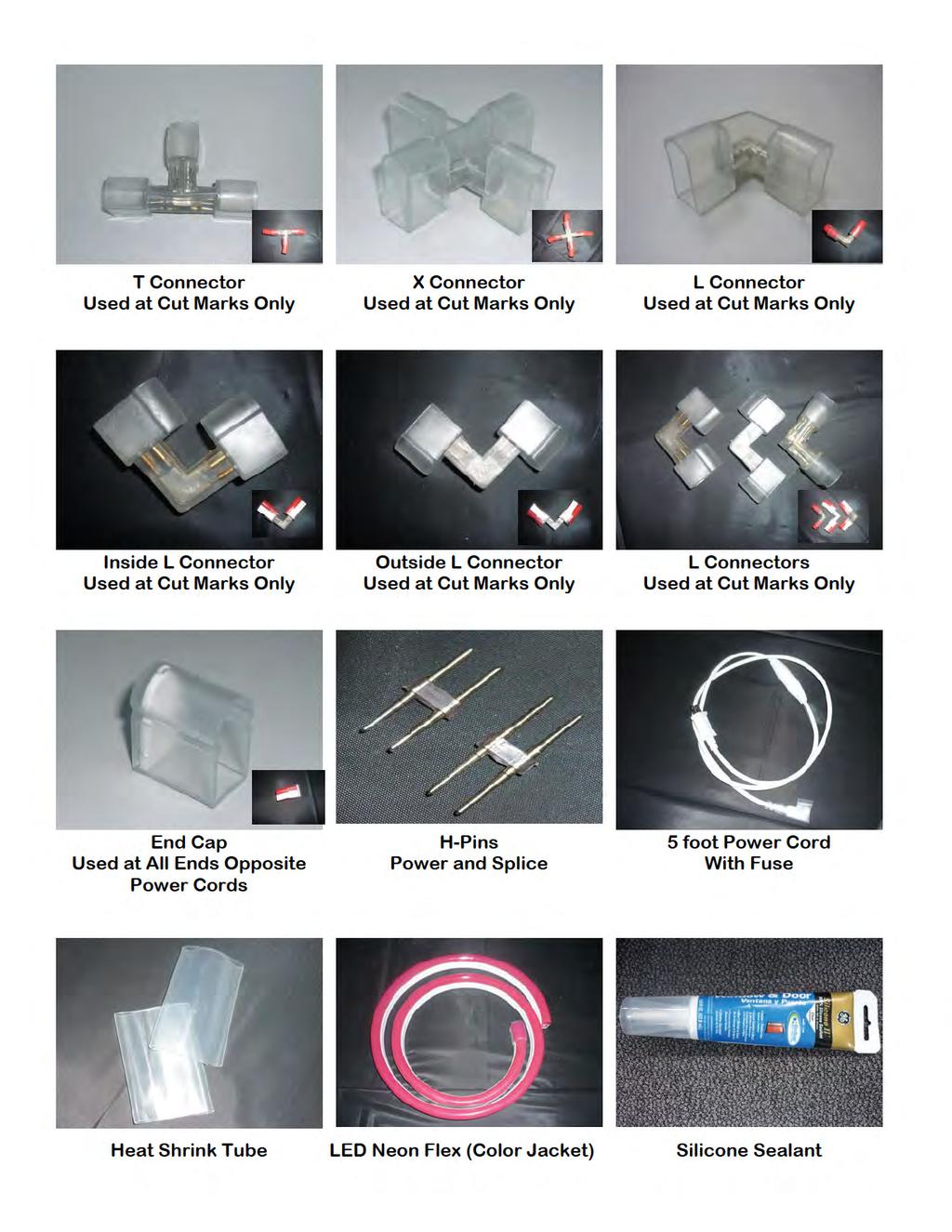
13 Using the L, X, T Connectors T Connector X Connector L Connector The assembly procedure for all accessory connectors is the same as connecting the power cord. 1. Cut the LED Neon Flex on the dotted cut mark 2. Spread the wires in the flex using the awl / pick. 3. Insert the barbed end of the power pin into the LED Neon Flex. 4. Align the H-pin with the holes in the connector. 5. Push the LED Neon Flex into the connector. 6. Slip the Heat Shrink Tube over the connection joint. 7. Heat the Shrink Tube with the Heat Gun. 8. Seal the edges of the Shrink Tube with Non-Conductive Silicone sealant.
Terminal Replacement Procedures
 HOW TO REPLACE CONNECTOR TERMINALS The terminal repair kits provide necessary tools and materials (terminals, wire seals, and splice connectors) to repair many damaged or faulty connector terminals. However,
Instructions for Lighting an S Scale Caboose
 Instructions for Lighting an S Scale Caboose The S Scale Caboose lighting kit is adaptable for most caboose models of rolling stock including American Flyer (TM) and contains the same components as found
Field Installed Connectors for TraceTek 7000-HUV Bulk Cable Installation Instructions
 TraceTek TT-7000-HUV-CK-MC-M/F Field Installed Connectors for TraceTek 7000-HUV Bulk Cable Installation Instructions Description These instructions describe field connecting of TT7000-HUV Bulk Sensing
PAK Drum Roll Top Assembly Instructions. Note: 2 people will be required to assemble roll top
 PAK901 4 Drum Roll Top Assembly Instructions Note: 2 people will be required to assemble roll top PLEASE READ ASSEMBLY INSTRUCTIONS CARFULLY Tools required: 5/8 Socket & Ratchet 9/16 Deep Well Socket &
Service Bulletin Terminal Replacement Instructions (Replaces , dated May 2, 1995) December 18, 2000 ALL
 December 18, 2000 ALL") Service Bulletin 00-039 Applies To: ALL December 18, 2000 Terminal Replacement Instructions (Replaces 95-007, dated May 2, 1995) These terminal replacement instructions apply to these kits and tools: Terminal
Service Bulletin 00-039 Applies To: ALL December 18, 2000 Terminal Replacement Instructions (Replaces 95-007, dated May 2, 1995) These terminal replacement instructions apply to these kits and tools: Terminal
Max Launch Abort System Prod. No *Kevlar is a registered trademark of Dupont
 Flying Model Parts List Max Launch Abort System Prod. No. 3014 A 11820 - Body Tube 3.5 Diam x 5.5" Long B 11824 - Orange Capsule Base Shoulder Ring C 16032 - Laser-cut Ring motor mount rear D 16033 - Laser-cut
unit 3: GENErAL ElectriCAL SySTEM DiAGNOSiS
 Electrical/Electronic Systems unit 3: GENErAL ElectriCAL SySTEM DiAGNOSiS lesson 4: wire and connector repairs I. Connector repairs A. Connector repairs involve fixing damaged wires. Wires are marred due
Assembly Instructions
 Unite Panel System Hinge Door July 2016 #12 x / slotted hex washer head bolt Figure 1 threshold bracket frame Detail F threshold bracket threshold bracket (installed) #12 x / slotted hex washer head bolt
Splice-In Sequential Tail Lights Installation Guide (96-04)
") Splice-In Sequential Tail Lights Installation Guide (96-04) The below installation instructions work for the following products: Mustang Sequential Taillights Kit - Splice-in (96-04) Please read through
Splice-In Sequential Tail Lights Installation Guide (96-04) The below installation instructions work for the following products: Mustang Sequential Taillights Kit - Splice-in (96-04) Please read through
The Ballistic Blaster Rocket Kit should contain the following items. If anything is missing, call Customer Service at
 Ballistic Blaster User Guide Materials Included The Ballistic Blaster Rocket Kit should contain the following items. If anything is missing, call Customer Service at 800-358-4983. Body tube, 6-1/2" long,
Chapter 6 Frame And Lens Repairs
 Chapter 6 Frame And Lens Repairs 6.1 General Information All maintenance on the frame of the EXO Full-Face mask can be accomplished with common hand tools. 6.2 Lens Replacement Tools required: Dow DC-111
RoofScreen Mfg., Inc. DryCap Installation Manual Updated Introduction This manual Application System Overview...
 DRYCAP INSTALLATION MANUAL WWW.ROOFSCREEN.COM Toll Free 866 766 3727 Introduction... 2 This manual... 2 Application... 2 System Overview... 2 Components... 2 DryCap... 2 End Caps... 2 Cleats... 3 Thread
INSTRUCTION MANUAL. Force Transducer Output Tube Repair Kit
 INSTRUCTION MANUAL Model 400-TR Force Transducer Output Tube Repair Kit June 4, 2004, Revision 5 Copyright 2004 Aurora Scientific Inc. Aurora Scientific Inc. 360 Industrial Pkwy. S., Unit 4 Aurora, Ontario,
Recommended Equipment and Tools
 Recommended Equipment and Tools [1] Philips Screwdriver [2] Flat Blade Screwdriver [3] 1/8 Hex Driver [4] Needle-nosed Pliers [5] X-acto Knife [6] Soft Foam Pad (or equivalent) Equipment and Tools PAGE
GORE Aerospace Ethernet Cables
 Termination Instructions The following procedures are based on Gore s best practices for terminating GORE Aerospace with the Amphenol Oval Contact System (OCS) for both plug and receptacle versions. These
Water Line and Water Line Assembly Gasket
 1 Preparation for Repair 1) Remove tip from scaler 2) Remove scaler from air supply 3) Remove gasket from back end of scaler. Examine gasket for obvious wear or disfigurement. Replace if necessary. 2 Remove
Side Light Frame Pack Assembly Instructions
 Please read this complete set of assembly instructions before starting the installation and only when you understand the construction method start to follow the step by step guide. IDENTIFY THE PACK CONTENTS
American Morse Equipment
 American Morse Equipment Thank you for purchasing an American Morse Porta Paddle-II Kit. We redesigned the original Porta Paddle for ease of assembly & provide all parts finished and ready for assembly,
IMPORTANT INSTALLATION GUIDE VALENCIA ANGLE CORNER SHOWER READ ALL INSTRUCTIONS CAREFULLY BEFORE STARTING THE INSTALLATION
 INSTALLATION GUIDE VALENCIA ANGLE CORNER SHOWER SEALANT REQUIRED TO COMPLETE THIS INSTALLATION: (Supplied) Sika Sikasil NG (Arctic White) To seal the WHITE shower door and returns to the shower tray. Usage:
K-Jetronic (CIS) Barb Insertion Tool Instructions
 Barb Insertion Tool Instructions") K-Jetronic (CIS) Barb Insertion Tool Instructions Rev. J Effective: 04-AUG-2018 Unobt ainium Supply Co. 523 Longley Rd Groton, MA 01450 978.448.2110 www.unobtainiumsupply.com Contents K-Jetronic (CIS)
K-Jetronic (CIS) Barb Insertion Tool Instructions Rev. J Effective: 04-AUG-2018 Unobt ainium Supply Co. 523 Longley Rd Groton, MA 01450 978.448.2110 www.unobtainiumsupply.com Contents K-Jetronic (CIS)
SLATTEX (Textured Slatwall) INSTALLATION GUIDE
 INSTALLATION GUIDE") SLATTEX (Textured Slatwall) INSTALLATION GUIDE Preparing for the Installation: Here are some suggestions to help you to help you simplify the installation process and maximize the beauty of your 3D Textured
SLATTEX (Textured Slatwall) INSTALLATION GUIDE Preparing for the Installation: Here are some suggestions to help you to help you simplify the installation process and maximize the beauty of your 3D Textured
Side Light Frame Pack Assembly Instructions
 Side Light Frame Pack Assembly Instructions Please read this complete set of assembly instructions before starting the installation and only when you understand the construction method start to follow
MMD Convertible Styling Bar Customer Installation Guide
 MMD Convertible Styling Bar Customer Installation Guide TOOLS REQUIRED/RECOMMENDED: Electric Drill 1 Forstner Bit (Hole Saw) 1 3/8 Hole Saw (manual calls for 1 ¾ ) 1/8, 3/8 & ¾ Drill Bits Rivet Gun Trim
Repairing Microsoft Wedge Touch Mouse Battery Cover Retaining Clip
 Repairing Microsoft Wedge Touch Mouse Battery Cover Retaining Clip Disassembly, repair and reassembly of Wedge Touch mouse when the battery cover will not stay closed. Also is a good guide to repair other
SERIES 360. Single Hung Windows. NOTE: Read instructions completely before attempting any installation.
 Installation Instructions SERIES 360 Single Hung Windows Page 2: Opening Preparation and Wood Buck Installation and Figure 1 Page 3-5: Installation Instructions for Series 360 WINDOWS Page 6: Figure 2:
 www.wildmanconstruction.com Changing your toilet is an easy project that should take half a day or less. The most common toilet has a separate tank that mounts on top of the bowl. These instructions apply
Installation Instructions for Vista Air Vertically Folding Walls
 Installation Instructions for Vista Air Vertically Folding Walls Use these instructions in conjunction with your shop drawings to see the specifics that are particular to the model you are installing.
Reasons for reissue are in Section 6, REVISION SUMMARY.
 Figure 1 This instruction sheet covers the application of OPTIMATE FSMA Fiber Optic Connector Types 905 and 906 for data and telecommunications applications. Base part numbers which apply to each type
BSM, GSM & GSS. Joint Kit Instruction. (Modified for IMPACT) (NSF Certified) Curved Glass Fresh Meat Delicatessen and Seafood Merchandisers
 (NSF Certified) Curved Glass Fresh Meat Delicatessen and Seafood Merchandisers") BSM, GSM & GSS Joint Kit Instruction (Modified for IMPACT) (NSF Certified) Curved Glass Fresh Meat Delicatessen and Seafood Merchandisers February, 1999 JOINT ASSEMBLY PARTS LIST Item Quantity Description
BSM, GSM & GSS Joint Kit Instruction (Modified for IMPACT) (NSF Certified) Curved Glass Fresh Meat Delicatessen and Seafood Merchandisers February, 1999 JOINT ASSEMBLY PARTS LIST Item Quantity Description
Pump Replacement Manual. Bill Wallace by Wallace Marine Services, Inc.
 by Wallace Marine Services, Inc. Maintain Your Equipment The Easy Way Bill Wallace 843-693-4336 info@willyvac.com www.willyvac.com Pump Replacement Manual 1 How to change the water pump on the Willy Vac
Bearing Overhaul Instructions for: Tallboy (.1) 2009
 2009") Bearing Overhaul Instructions for: Tallboy (.1) 2009 Tools Needed: 7900 Removal Tool 7902 Removal Tool 7900/7902/6902 Press Tool Grease Gun (included with frame) (2) ll/16" or adjustable wrenches 9/16"
Bearing Overhaul Instructions for: Tallboy (.1) 2009 Tools Needed: 7900 Removal Tool 7902 Removal Tool 7900/7902/6902 Press Tool Grease Gun (included with frame) (2) ll/16" or adjustable wrenches 9/16"
FIG. #1 - ASD-90 & USD-90 Shower Door Assembly
 Installation Instructions for the Accent/Euro Collection FIG. #1 - ASD-90 & USD-90 Shower Door Assembly #1021 #1021 1 23 25 2 #1020 6 5 12 #1020 9 24 9 8 Hinge Assembly 2109, 2201, 2212, 2213, 2220 7 Please
PRINTER REPAIR ARTICLE HP LJ 4345/M4345 Swing Plate Replacement
 a1 output bin a2 DUPLEXER a4 FORMATTER COVER a5 FORMATTER a3 fuser entr. guide PRINTER REPAIR ARTICLE HP LJ 4345/M4345 Swing Plate Replacement Grinding noise near the fuser means it is time to replace
Bushwacker Jeep Flat Style Fender Flares Front Pair
 Bushwacker Jeep Flat Style Fender Flares Front Pair Note: These instructions involve cutting parts of your vehicle. Please read all instructions prior to starting. Installation Time: 3-4 Hours Tools Required:
Motorized or Crank Operated Fortress Zipper Track Shade with Housing and Side Track Installation Instructions
 Motorized or Crank Operated Fortress Zipper Track Shade with Housing and Side Track Installation Instructions Tools Needed Drill 3/8 Metal Drill Bit ¼ Masonry Drill Bit Measuring Tape Pencil 4 Level Phillips
How To: Fit new trim including chrome door handles
 How To: Fit new trim including chrome door handles Ever since upgrading to a V6 from my Silver and Black I've always been disappointed with the interior. It just felt a bit drab but when I worked out what
Please read and understand all instructions before beginning. These instructions cover impact and non-impact aluminum French Door 650/750.
 The performance and proper operation of a door is only as good as the installation. By following these instructions, the probability of a good installation greatly increases. Please read and understand
Side and rear window, assembly overview
 64-7 Side and rear window, assembly overview 1 - Side/rear window Removing Unbroken Page 64-9 Broken Page 64-11 Installing Page 64-13 Curing time Page 64-21 Re-sealing Page 64-25 2 - PUR adhesive sealant
35 mw HeNe Laser Ballast Resistor Insulation Upgrade Instructions
 35 mw HeNe Laser Ballast Resistor Insulation Upgrade Instructions A video that demonstrates the laser upgrade process can be found at: http://www.reoinc.com/site/14309- instructions General Notes Please
Instructions to fit Emulator in place of floppy drive M.D.R.
 Instructions to fit Emulator in place of floppy drive M.D.R. Before starting, read through all the following instructions, and then when you do begin, read each number section before attempting that particular
UNIT No FRAMELESS PIVOT SHOWER DOOR
 INSTALLATION INSTRUCTIONS UNIT No. 3600 FRAMELESS PIVOT SHOWER DOOR NEED INSTALLATION HELP? Call 1-800-45-BASCO (452-2726) Monday - Friday 8:00 A.M. - 4:30 P.M. Eastern Time QCI0020 Rev. 3 Page 1 of 8
GORE Aerospace Ethernet Cables
 Termination Instructions The following procedures are based on Gore s best practices for terminating GORE Aerospace with the Carlisle Octax Connector System for both socket and plug versions. These procedures
Tools Required For Servicing: Needle Nose Pliers
 Danger Caution Danger of Life Do not attempt to perform service on a hot heat gun. Always allow unit to cool completely and disconnect from power source before performing any service on the heat gun. Fire
Block Frame Inovo Patio Door/Transom/Sidelite Field Mulling Instructions. simonton.com/installation. If mulling sidelites, skip to Step 5.
 Effective Date: 10/1/17 Tools Needed Kit Contents Safety Glasses Cordless Drill Phillips Screw Bit Two-step Drill Bit (3/8-1/8 ) Utility Knife Interior Mullion Exterior Mullion Cover Hardware Kit Clamps
Written By: Brittany McCrigler
 Installing a Plastic Snap Using a Hand Press This guide shows you how to replace a plastic snap using a hand press Written By: Brittany McCrigler ifixit CC BY-NC-SA www.ifixit.com Page 1 of 13 INTRODUCTION
Handrail H Series. Product Installation. Instructions. Installation Instructions For. Wall Mounted and Freestanding Round Handrails
 Product Installation Installation Instructions For Instructions Handrail H Series Installation Instructions for Wall Mounted and Freestanding Round Handrails Step Nosing F Series Concrete and Timber Step
Youth Explore Trades Skills
 Youth Explore Trades Skills Connecting Wires Description All lights in a house must have proper wire connections in order to work. Residential electrical work requires electricians to join wires together
Fine Feathers. Make a pair of silver-clay peacock earrings
 Fine Feathers Make a pair of silver-clay peacock earrings Objectives Create a base design which can stand alone or work with embellishments Add color to silver with permanent markers Make a narrow channel
ALUMINUM AIR TRIM INSTALLATION INTRODUCTION
 ALUMINUM AIR TRIM INSTALLATION INTRODUCTION KEISER CORPORATION has always taken pride in designing and engineering the highest quality equipment on the market. This means that you will receive years of
Jewelry Basics 101. Basic Wire Loops For best results, use both chain-nose and round-nose pliers. Method 2 Bend then cut. Method 1 Cut then bend
 Jewelry Basics 101 #68-007-01 Basic Wire Loops For best results, use both chain-nose and round-nose pliers. Method 2 Bend then cut Use non-serrated chain-nose pliers to bend the wire just above the bead.
BrewsBySmith.com STC DIY Kit
 BrewsBySmith.com STC-1000 + DIY Kit Contact Information: Greg Smith www.brewsbysmith.com greg@boostbysmith.com I. Hardware Included: STC-1000 flashed with latest software (v1.06 currently) (if purchased)
Sentinel Series Cigar Humidor End Tables
 Sentinel Series Cigar Humidor End Tables Assembly Instructions Models: Sentinel 500, 1000 and 1500 Style: Contemporary SENTINEL ASSEMBLY INSTRUCTIONS Congratulations! You have purchased a superior cigar
BIPPMM03 (Published) Book specs- Dates: / / Lang: ENG01 Applic: PPM
 Book specs- Dates: / / Lang: ENG01 Applic: PPM") BIPPMM03 (Published) Book specs- Dates: 20060412 / 20060412 / 20060412 Lang: ENG01 Applic: PPM Installing the Milnor Diaphragm in the Single Stage Press This document applies to models MP160Axx, MP1604xx,
BIPPMM03 (Published) Book specs- Dates: 20060412 / 20060412 / 20060412 Lang: ENG01 Applic: PPM Installing the Milnor Diaphragm in the Single Stage Press This document applies to models MP160Axx, MP1604xx,
Application Note. Bowser-Stewart VO-1000 Tsunami Digital Sound Decoder Installation Notes
 Application Note Overview This application note describes how to install a TSU-1000 Digital Sound Decoder into the Bowser-Stewart VO-1000 Locomotive. Skill Level 4: The entire installation can be completed
NEW Plastic Sweep Installation Instructions 40/30 Loop Antennas
 40/30 Loop Antennas PG 1 Preparing the telescoping pole tips for the 40/30 loop elements Extend the telescoping poles to full length by firmly locking each section of the pole in place. A good methodology
1.0 Tool Components and Operation Instructions
 DBS-2200 MANUAL BANDING TOOL FOR 1/8 STAMPED BUCKLE BANDS DATASHEET SEE PAGE 18 FOR IMPORTANT INFORMATION CONCERNING LIMITED WARRANTY AND LIMITATION OF LIABILITY. INTRODUCTION The Daniels DBS-2200 (M81306/1B)
Insolroll Clutch Operated Shades Installation Instructions Installation Instructions
 All clutch operated shades are shipped fully assembled and ready for installation. Mounting screws are not provided. Screws for chain guide installation to meet the child safety standards are provided.
For additional assistance call
 The following pages will help guide you through the process of assembling your new 48 custom prize wheel. Choose an assembly area with plenty of room to lay your pieces on the floor and also a bench or
LOCKN LOAD FIRST TIME INSTALLATION
 LOCKN LOAD TM TRACK MOUNTING KIT NISSAN NAVARA D40 2004-2015 2 BAR TRACK HEAVY DUTY ROOF RACK SYSTEM MAX VEHICLE ROOF LOAD RATING: 100KG TOTAL LOAD EQUALS WEIGHT OF ROOF RACKS + ACCESSORIES + CARGO FIRST
MS2 Straight Key Kit Assembly Manual
 American Morse Equipment MS2 Straight Key Kit Assembly Manual Thank you for purchasing our MS2 Miniature Straight Key Kit! Please take a few minutes to look over these instructions before starting assembly.
REPAIR INSTRUCTIONS. Cat. No Cat. No MILWAUKEE ELECTRIC TOOL CORPORATION. SDS Max Demolition Hammer. SDS Max Rotary Hammer
 Cat. No. 9-0 SDS Max Demolition Hammer Cat. No. -0 SDS Max Rotary Hammer MILWAUKEE ELECTRIC TOOL CORPORATION W. LISBON ROAD BROOKFIELD, WISCONSIN 00-0 8-9-0 d 000 8-9-0 d Special Tools Require Forcing
SUPERSEDED REVISION. Reasons for reissue of this instruction sheet are provided in Section 7, REVISION SUMMARY.
 PRO BEAM Jr. EB cable plug connectors are designed to be installed onto jacketed fiber optic cable with KEVLAR strength members. The connector must be assembled using a cable plug connector shell kit,
Harmony Remote Repair
 Harmony Remote Repair harmonyremoterepair.com How to install your new Harmony One Front Cover/Touch Screen Important! Before you begin working on your Harmony One, you must discharge any static electricity
Removing outter components
 Y Axis Motor Replacement Replacing the Y axis motor is a process that requires the individual to be somewhat mechanically inclined and can follow detailed instructions. If any of the following steps are
VALENCIA CORNER DOOR WITH RETURN
 VALENCIA CORNER DOOR WITH RETURN INSTALLATION GUIDE SEALANT REQUIRED TO COMPLETE THIS INSTALLATION: ( not supplied) Sika Silaflex NG To seal the WHITE shower door and returns to the shower tray. Usage:
Custom Pendant- Hardwire Assembly and Installation Instructions
 Custom Pendant- Hardwire Assembly and Installation Instructions CAUTION: BEFORE INSTALLING FIXTURE, MAKE SURE THE POWER TO THE CIRCUIT IS TURNED OFF AT THE MAIN FUSE BOX / CIRCUIT BREAKER UTILITY BOX.
ScaleRCHelis.com V Light Controller Kit
 Thank you for purchasing the ScaleRCHelis.com V1.1 450 Light Controller Kit. This is something you can build in under a hour with some simple soldering equipment. Your kit will include all the parts necessary
P A R T I. Basic Techniques
 P A R T I Basic Techniques C H A P T E R 1 Getting Started Edward Steichen, Lotus, Mount Kisco, New York, 1915. Reprinted with permission of Joanna T. Steichen. GETTING STARTED It is not difficult to take
Basic steps to time the Gammill quilting machine s rotary sewing hook
 Basic steps to time the Gammill quilting machine s rotary sewing hook 1.) Turn the machine off and unplug it. 2.) With the needle bar in the raised position, remove the bobbin and bobbin case. 3.) Remove
ELECRAFT Application Note
 ELECRAFT Application Note Front Panel Microphone Circuit Modification Revision A, November 12, 2008 Copyright 2008, Elecraft, Inc., All Rights Reserved Background Some K3 owners have noted distorted transmit
7878 K940. Checkpoint Antenna. Kit Instructions. Issue B
 7878 K940 Checkpoint Antenna Kit Instructions Issue B Revision Record Issue Date Remarks A July 7, 2009 First issue B Nov2013 Revised the Checkpoint installation procedures for 7878 and 7874 scanners Added
2 Recommended Tools / Supplies
 Bias Scout TM Kit Assembly Manual Version 3.1 25 March 2015 1 Inventory of Parts 1 ea octal socket 1 ea octal base, brown (1 3/16" dia x 7/8" high) 1 ea 1.0 / 1W metal oxide, flame proof resistor 1 ea
Sentinel Series Cigar Humidor End Tables
 Sentinel Series Cigar Humidor End Tables Assembly Instructions Models: Sentinel 500, 1000 and 1500 Style: Traditional SENTINEL ASSEMBLY INSTRUCTIONS Congratulations! You have purchased a superior cigar
SIMPLER BETTER FASTER
 SIMPLER BETTER FASTER 1. FITTING RING BEAMS DETAILS Always work anti-clockwise viewed from outside the roof. Each bar should be sequentially numbered, i.e. 1, 2, 3. Select the ring beam, position the left
ADJUST-A-VIEW HALF CIRCLE INSTALLATION INSTRUCTIONS
 Omega Mfg. Corporation Two Rivers, WI (800) 874-9594 www.adjustaview.com Proudly Serving Customers Since 1976 Page 1 of 7 MATERIAL LIST ADJUST-A-VIEW User Instructions ADJUST-A-VIEW Installation Instructions
4. Partially open the operating panel and tilt the top toward the interior of the door (Figure 4). Lift the panel off the sill and set it aside.
. Lift the panel off the sill and set it aside.") Effective Date: 10/1/2017 Tools Needed Kit Contents Hardware Kit Safety Glasses Cordless drill Phillips screw bit Two-step drill bit (3/8-1/8 ) utility knife Interior Mullion Exterior Mullion Cover clamps
Effective Date: 10/1/2017 Tools Needed Kit Contents Hardware Kit Safety Glasses Cordless drill Phillips screw bit Two-step drill bit (3/8-1/8 ) utility knife Interior Mullion Exterior Mullion Cover clamps
101B, 210X, ELM, VSTB Installation Manual
 101B, 210X, ELM, VSTB Installation Manual 99-16105-I001 Copyright 2010 by ALL rights reserved. Information in this document is subject to change without notice. Companies, names and data used in examples
ipad 3 4G Home Button Control Board Replacement
 ipad 3 4G Home Button Control Board Replacement Replace the home button control board in your ipad 3. Written By: Brett Hartt ifixit CC BY-NC-SA www.ifixit.com Page 1 of 28 INTRODUCTION This guide will
Written By: Jeff Suovanen
 iphone XS Max Lower Speaker Replacement Remove or replace the main loudspeaker on the bottom edge of the iphone XS Max. Written By: Jeff Suovanen ifixit CC BY-NC-SA www.ifixit.com Page 1 of 23 INTRODUCTION
Mini Backpacks as Party Treat Bags
 Published on Sew4Home Mini Backpacks as Party Treat Bags Editor: Liz Johnson Thursday, 07 July 2016 1:00 Birthday party treat bags are usually flimsy plastic things filled with candy and trinkets those
OSBORNE SHOWER DOOR INSTALLATION
 SKU(s): 939719, 939720, 939721 OSBORNE SHOWER DOOR INSTALLATION BEFORE YOU BEGIN We recommend consulting a professional if you are unfamiliar with installing this type of product. Signature Hardware accepts
HEADLIGHT CONNECTOR REPLACEMENT
 Classification: Reference: Date: EL01-006a ITB01-021a October 17, 2003 HEADLIGHT CONNECTOR REPLACEMENT IMPORTANT: THIS BULLETIN HAS BEEN REVISED. The Service Procedure was updated with new information
AirBorn Inc. Product Technical Bulletin #31
 AirBorn Inc. Product Technical Bulletin #31 INSTALLATION OF R-SERIES CONNECTORS WITH PRESS-FIT TERMINATIONS 1. PURPOSE This purpose of this application note is to assist customers in the proper application
B A T H R O O M G L A S S
 mistley B A T H R O O M G L A S S vaug16 Page 2 Thank you for purchasing this Trinity shower screen. Please study these instructions carefully before assembly and installation and check all supplied parts
Repairing MagSafe Connector
 Repairing MagSafe Connector Written By: Dave Fixedit ifixit CC BY-NC-SA www.ifixit.com Page 1 of 10 INTRODUCTION Magsafe cables are known to break off close to the connector. This article explains how
Powerbook G3 Lombard (1999) USB Repair Manual
 USB Repair Manual") Powerbook G3 Lombard (1999) USB Repair Manual Copyright 2003 Powerbookmedic.com. All rights reserved. Any portion of this manual may not be copied, reproduced, or distributed without the express written
Powerbook G3 Lombard (1999) USB Repair Manual Copyright 2003 Powerbookmedic.com. All rights reserved. Any portion of this manual may not be copied, reproduced, or distributed without the express written
Phone # La Jolla Doors. Block Frame Installation Manual Aluminum Frame with either Vinyl or Aluminum Panels
 Phone # 800-440-8785 www.lajolladoors.com La Jolla Doors Block Frame Installation Manual Aluminum Frame with either Vinyl or Aluminum Panels Thank you for choosing La Jolla Doors In this manual you will
Starving Student II. Starving Student II. SS2 guide. Written By: 6L guides.diyaudio.com/ Page 1 of 24
 SS2 guide Written By: 6L6 2019 guides.diyaudio.com/ Page 1 of 24 INTRODUCTION This is a build guide for the hybrid headphone/pre-amplifier. You can buy a kit at the SSII product listing on the diyaudio
Carry Sew Table and Hoop Bag Created by Joy Harvey
 www.bernina.com.au Carry Sew Table and Hoop Bag Created by Joy Harvey Materials List What to do with all those leftover cords, ribbon, braids, pearls and sequins? Your answer, foot #12C my favourite presser
CAUTION. It is the responsibility of the INSTALLER to ensure that the installation complies with council and or local authority bylaws.
 INSTALLATION GUIDE SAPPHIRE ROUND CORNER SLIDING SHOWER CAUTION It is the responsibility of the INSTALLER to ensure that the installation complies with council and or local authority bylaws. Instructions,
Connectors for Ribbon Flex and Soldering Tips
 Connectors for Ribbon Flex and Soldering Tips 11235 West Bernardo Court, Suite 102 San Diego, CA 92127 888-880-1880 Fax: 707-281-0567 EnvironmentalLights.com Instructions for Connecting Power or Control
Frameless Bypass Slider
 INSTALLATION INSTRUCTIONS Frameless Bypass Slider QCI-5301 3/8 or 1/4 Glass Bypass Slider with Exposed Rollers QCI5301 Rev 1 Page 1 Certified 6/5/2017 Tools: To install your New Shower Enclosure, you may
Headlight LED's. Installing LEDs in the headlights:
 Headlight LED's I want to give advance special thanks to Butch Vincent for the following article he shared with all of us at www.ridersrally.com. He had posted a picture of his headlights with inserted
MIL-STD B (SH) UPDATE
 UPDATE") MIL-STD-2042-5B (SH) UPDATE Method 5A1 Insert Equipment and materials (to be added to table 5A1-I) Pliers 3.2.2.2 Cable and fiber preparation for Fiber Systems International backshells. Step 1: Ensure
MIL-STD-2042-5B (SH) UPDATE Method 5A1 Insert Equipment and materials (to be added to table 5A1-I) Pliers 3.2.2.2 Cable and fiber preparation for Fiber Systems International backshells. Step 1: Ensure
Model 5400H / 7000H Illustrated Installation Instructions
 Model 5400H / 7000H Illustrated Installation Instructions Contractors Wardrobe DESIGNERS MANUFACTURERS 261 Avenue Hall Valencia, CA 91355 (661) 257-1177 (661) 257-4907 TOLL FREE: (800) CW-DOORS (800) 293-6677
Arched Top Lantern Pendant Assembly and Installation Instructions. Country of Destination: US/CN UK/EU/AUS Middle East
 CAUTION: Arched Top Lantern Pendant Assembly and Installation Instructions Country of Destination: US/CN UK/EU/AUS Middle East BEFORE INSTALLING FIXTURE, MAKE SURE THE POWER TO THE CIRCUIT IS TURNED OFF
TRUE TECHNICAL SERVICE MANUAL - ALL MODELS. DOORS/DRAWERS/LIDS
 DOORS/DRAWERS/LIDS 55 56 NOTES DOORS/DRAWERS/LIDS Swing s 73 74 NOTES INSTALLATION OF A GDM-SWING DOOR Phillips Head Screwdriver (2) - 1/8" Drift Punches (forged) Top Bracket NOTE: It may be necessary
Strata. urniture. Adriana Instructions. Parts in the Arm Box: Parts in the Body Box: Watch our assembly videos at
 1A Watch our assembly videos at www.strataf.com/videos Parts in the Arm Box: Arm - Outside View Arm - Inside View 1B Parts in the Body Box: Back Deck x 1 Seat Deck x 1 with the Feet attached Back Panel
METAL BLINDS. Deluxe GETTING STARTED OPTIONAL HARDWARE. A few simple tools are required: STANDARD HARDWARE
 METAL BLINDS Deluxe GETTING STARTED OPTIONAL HARDWARE A few simple tools are required: Steel Tape Measure Pencil Level Hold Down Brackets with Screws Extension Bracket Power Drill and Drill Bits Flathead
ROMAN AND. Roller Lift System Continuous Cord Loop GETTING STARTED BRACKET INFORMATION INSIDE MOUNT. A few simple tools are required:
 ROMAN AND WOVEN WOOD SHADES Roller Lift System Continuous Cord Loop GETTING STARTED BRACKET INFORMATION A few simple tools are required: The brackets you received with your product are REQUIRED for proper