MIG WELDER. Metal man Industrial Welder Operating Instructions and Parts Manual MIG 135
|
|
|
- Vincent Stafford
- 5 years ago
- Views:
Transcription

1

2
3 Heat Settings (4) To adjust output voltage/heat settings. Refer to the set up chart inside the wire feed compartment Welding Cable and MIG gun The welding wire is driven through the welding cable and MIG gun to the work piece. It is attached to the drive system, the gun trigger activates the drive motor. Ground Cable and Clamp The ground cable/clamp are attached to the work piece to complete the circuit, allowing the flow of current needed to weld Thermal Indicator If the duty cycle of the welder is exceeded the internal temperature will exceed safe temperatures and the machine will shut down. The Thermal overload light will come on indicating this, allow about 15 minutes for cool down before the light will go off and the temperature to fall into an allowable operating range. Power Cord The power cord connects the welder to the 115 volt power supply. Plug the 15 amp plug into a 115 volt/20 amp receptacle to supply power to the welder. General Safety Information 1.1 Your Welding Environment -Keep the environment you will be welding in free from flammable materials. -Always keep a fire extinguisher accessible to your welding environment. -Always have a qualified person install and operate this equipment. -Make sure the area is clean, dry and ventilated. Do not operate the welder in humid, wet or poorly ventilated areas. -Always have your welder maintained by a qualified technician in accordance with local, state and national codes. -Always be aware of your work environment. Be sure to keep other people, especially children, away from you while welding. -Keep harmful arc rays shielded from the view of others. -Mount the welder on a secure bench or cart that will keep the welder secure and prevent it from tipping over or falling. 1.2 Your Welder s Condition -Check ground cable, power cord and welding cable to be sure the insulation is not damaged. Always replace or repair damaged components before using the welder. -Check all components to ensure they are clean and in good operating condition before use. 1.3 Use of Your Welder Do not operate the welder if the output cable, electrode, MIG gun, wire or wire feed system is wet. Do not immerse them in water. These components and the welder must be completely dry before attempting to use them. -Follow the instructions in this manual. -Keep welder in the off position when not in use. 3

 and safety glasses while welding.")
4 -Connect ground lead as close to the area being welded as possible to ensure a good ground. -Do not allow any body part to come in contact with the welding wire if you are in contact with the material being welded, ground or electrode from another welder. -Do not weld if you are in an awkward position. Always have a secure stance while welding to prevent accidents. Wear a safety harness if working above ground. -Do not drape cables over or around your body. -Wear a full coverage helmet with appropriate shade (see ANSI Z87.1 safety standard) and safety glasses while welding. -Wear proper gloves and protective clothing to prevent your skin from being exposed to hot metals, UV and IR rays. -Do not overuse or overheat your welder. Allow proper cooling time between duty cycles. -Keep hands and fingers away from moving parts and stay away from the drive rolls. -Do not point MIG gun at any body part of yourself or anyone else. -Always use this welder in the rated duty cycle to prevent excessive heat and failure. 1.4 Specific Areas of Danger, Caution or Warning Electrical Shock Electric arc welders can produce a shock that can cause injury or death. Touching electrically live parts can cause fatal shocks and severe burns. While welding, all metal 4 components connected to the wire are electrically hot. Poor ground connections are a hazard, so secure the ground lead before welding. -Wear dry protective apparel: coat, shirt, gloves and insulated footwear. -Insulate yourself from the work piece. Avoid contacting the work piece or ground. - Do not attempt to repair or maintain the welder while the power is on. -Inspect all cables and cords for any exposed wire and replace immediately if found. -Use only recommended replacement cables and cords. -Always attach ground clamp to the work piece or work table as close to the weld area as possible. -Do not touch the welding wire and the ground or grounded work piece at the same time. -Do not use a welder to thaw frozen pipes. Fumes and Gases -Fumes emitted from the welding process displace clean air and can result in injury or death. -Do not breathe in fumes emitted by the welding process. Make sure your breathing air is clean and safe. -Work only in a well-ventilated area or use a ventilation device to remove welding fumes from the environment where you will be working. -Do not weld on coated materials (galvanized, cadmium plated or containing zinc, mercury or barium). They will emit harmful fumes that are dangerous to breathe. If necessary use a ventilator, respirator with air

 and infrared (IR) rays that can cause injury to your eyes and skin. Do not look at the welding arc without proper eye protection.")
5 supply or remove the coating from the material in the weld area. -The fumes emitted from some metals when heated are extremely toxic. Refer to the material safety data sheet for the manufacturer s instructions. -Do not weld near materials that will emit toxic fumes when heated. Vapors from cleaners, sprays and degreasers can be highly toxic when heated. UV and IR Arc Rays The welding arc produces ultraviolet (UV) and infrared (IR) rays that can cause injury to your eyes and skin. Do not look at the welding arc without proper eye protection. -Always use a helmet that covers your full face from the neck to top of head and to the back of each ear. -Use a lens that meets ANSI standards and safety glasses. For welders under 160 Amps output, use a shade 10 lens; for above 160 Amps, use a shade 12. Refer to the ANSI standard Z87.1 for more information. -Cover all bare skin areas exposed to the arc with protective clothing and shoes. Flame-retardant cloth or leather shirts, coats, pants or coveralls are available for protection. -Use screens or other barriers to protect other people from the arc rays emitted from your welding. -Warn people in your welding area when you are going to strike an arc so they can protect themselves. Fire Hazards Do not weld on containers or pipes that contain or have had flammable, gaseous or liquid combustibles in them. Welding creates sparks and heat that can ignite flammable and explosive materials. -Do not operate any electric arc welder in areas where flammable or explosive materials are present. -Remove all flammable materials within 35 feet of the welding arc. If removal is not possible, tightly cover them with fireproof covers. -Take precautions to ensure that flying sparks do not cause fires or explosions in hidden areas, cracks or areas you cannot see. -Keep a fire extinguisher close in the case of fire. -Wear garments that are oil-free with no pockets or cuffs that will collect sparks. -Do not have on your person any items that are combustible, such as lighters or matches. -Keep work lead connected as close to the weld area as possible to prevent any unknown, unintended paths of electrical current from causing electrical shock and fire hazards. -To prevent any unintended arcs, cut wire back to ¼" stick out after welding. 5


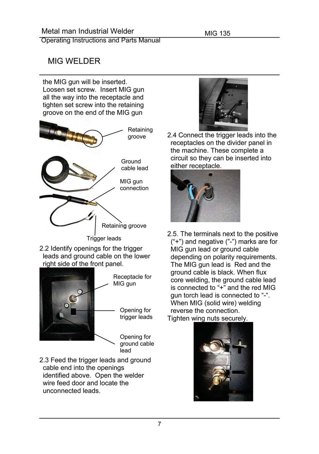
6 Hot Materials Welded materials are hot and can cause severe burns if handled improperly. -Do not touch welded materials with bare hands. -Do not touch MIG gun nozzle after welding until it has had time to cool down. Sparks/Flying Debris Welding creates hot sparks that can cause injury. Chipping slag off welds creates flying debris. -Wear protective apparel at all times: ANSI-approved safety glasses or shield, welder s hat and ear plugs to keep sparks out of ears and hair. Electromagnetic Field -Electromagnetic fields can interfere with various electrical and electronic devices such as pacemakers. -Consult your doctor before using any electric arc welder or cutting device -Keep people with pacemakers away from your welding area when welding. -Do not wrap cable around your body while welding. -Wrap MIG gun and ground cable together whenever possible. -Keep MIG gun and ground cables on the same side of your body. Shielding Gas Cylinders Can Explode High pressure cylinders can explode if damaged, so treat them carefully. -Never expose cylinders to high heat, sparks, open flames, mechanical shocks or arcs. -Do not touch cylinder with MIG gun. -Do not weld on the cylinder -Always secure cylinder upright to a cart or stationary object. -Keep cylinders away from welding or electrical circuits. -Use the proper regulators, gas hose and fittings for the specific application. -Do not look into the valve when opening it. -Use protective cylinder cap whenever possible 1.5 Proper Care, Maintenance and Repair -Always have power disconnected when working on internal components. - Do not touch or handle PC board without being properly grounded with a wrist strap. Put PC board in static proof bag to move or ship. -Do not put hands or fingers near moving parts such as drive rolls of fan Assembly 1. Tools required for assembly: Hexagon wrench (M8). 2. MIG gun/torch assembly 2.1 MIG gun/torch attachment- Locate the set screw inside the front panel on the front of the drive system on the terminal block where 6
7

8

9 on the outside edge of the wire spool and bend it over to hold the wire in place. Remove the spool of wire from the spool hub by removing the drive tensioning wing nut and hardware Removal of drive roller. Use the L shaped hex wrench in the accessory package, insert the wrench into the set screw in the drive roller and loosen by turning it counterclockwise. Pull the Drive Roller off of the Drive Roller Shaft., see following images using should face out. This identifies the inside groove the wire will line up with. Assemble the drive roller onto the drive roller shaft and use the L shaped hex wrench to tighten (turn clockwise) it in place. 4. Install the wire 4.1 Selecting the wire Available wire for this machine Wire Type MIG wire.023 inch MIG wire.030 inch Flux core wire.030 inch Flux core wire.035 inch Available Yes Yes Yes Yes 3.5 Based on the wire diameter select the correct groove using the following table: Wire Diameter Roller Groove.024 inch inch inch 0.9 The drive roller has two wire size grooves. When installing the drive roller, the number stamped on the drive roller for the wire size you are 9 MIG wires available are: mild steel, stainless steel or aluminum solid wire and must be used with shielding gas. Four or eight inch spools are available. NOTE: Burn through will occur if you attempt to weld mild or stainless steel thinner than 24 gauge. Remove all rusted wire, if the whole spool is rusty discard it.

10 4.2 Install the wire Electric shock can kill! Always turn the POWER switch OFF and unplug the power cord from the AC power source before installing wire. NOTE: Before installing, make sure that you have removed any old wire from the torch and cable assembly. This will help to prevent the possibility of the wire jamming inside the gun Liner. Be careful when removing the welding nozzle. The contact tip on this welder is live when the gun trigger is pulled. Make certain POWER is turned OFF Remove the nozzle and contact tip from the end of the gun assembly. See following images for reference system for smooth flow of the wire. See following figure Both 4 and 8 inch spools can be used, please see the following figure about the installation onto the spool hubs: The adjustment knob is designed to adjust the pressure tension of the wire spool. 8 spool Wing nut 4 spool 8 spool Adaptor Make sure the proper groove on the drive roller is in place for the wire installed. If not, change the drive roller as described above Remove the packaging from the spool of wire and then identify the leading end of the wire secured in a hole on the edge of the spool. DO NOT UNHOOK IT AT THIS TIME Place the spool on the spool hub with the wire coming off the bottom of the spool. The bottom of the spool aligns with inlet to the drive Setting the wire spool tension: a) Turn the spool of wire with one hand. b) Increase the spool tension by tightening (turn clockwise) the wing nut while turning the spool. Turn the spool while tightening the wing nut until the spool slows down and operator feels a slight drag. Stop tightening the wing nut, operator may need to repeat these steps until proper spool tension is achieved. NOTE: If TOO MUCH tension is applied to the wire spool, the wire will slip on the drive roller or will not be able to feed at all. If TOO LITTLE tension is
11 applied, the spool of wire will want to unspool itself when the trigger is released. Readjust the spool tension using the wing nut as necessary to correct for either problem After checking to make sure that your welder is disconnected from the AC power source, free the leading end of the wire from the spool, but DO NOT LET GO OF IT until it is secure in the drive system or the wire will unspool itself Using a wire cutter, cut the bent end off the leading end of the wire so that only a straight leading end remains Loosen the tension adjusting knob holding the drive tension arm in place and lift the tension arm up off the drive roller Insert the leading end of the wire into the inlet guide tube. Then push it across the drive roller and into the MIG gun/torch assembly about six inches. Make certain that the welding wire is actually going into the torch liner. If not, the wire will jam in the mechanism Be sure the wire lines up in the groove of the drive roller then place the drive tension arm back in place above the drive roller Position the quick release drive tension back up into position into the drive tension arm Tighten (turn clockwise) the drive tension adjusting knob until the tension roller is applying enough force on the wire to prevent it from slipping out of the drive assembly. Do not over tighten NOW YOU CAN LET GO OF THE WIRE Plug in and turn the welder ON. Set the VOLTAGE switch to the voltage (heat) setting recommended for the gauge metal that is to be welded. Refer to the set up chart on the inside of the wire feed compartment door Set the WIRE SPEED control in the middle of the wire speed range Straighten the MIG gun cable, pull the trigger on the welding torch to feed the wire through the torch assembly. When at least one inch of the wire sticks out past the end of the torch, release the trigger Turn the Power Switch to the OFF position Select a contact tip stamped with the same diameter as the wire being used. NOTE: Due to inherent variances in fluxcored welding wire, it may be necessary to use a contact tip one size larger than your flux core wire if wire jams occur Slide the contact tip over the wire (protruding from the end of the gun). Thread the contact tip into the end of the gun adaptor and tighten securely Install the nozzle on the gun assembly. To keep spatter from sticking to inside of the nozzle use anti-spatter spray or gel Cut off the excess wire that extends more than ¼ past the end of the nozzle Turn the welder ON

12 5. Setting the wire tension Arc flash can injure eyes! To reduce the risk of arc flash, make certain that the wire coming out of the end of the torch does not come in contact with work piece, ground clamp or any grounded material during the drive tension setting process or arcing will occur Press the trigger on the torch Turn the drive tension adjustment knob clockwise, increasing the drive tension until the wire seems to feed smoothly without slipping. 6.Gas installation Shielding gas cylinders and high pressure cylinders can explode if damaged, so treat them carefully. -Never expose cylinders to high heat, sparks, open flames, mechanical shocks or arcs. -Do not touch cylinder with MIG gun. -Do not weld on the cylinder. -Always secure cylinder upright to a cart or stationary object. -Keep cylinders away from welding or electrical circuits. -Use the proper regulators, gas hose and fittings for the specific application. When MIG wire is used, shielding gas is required. 1. Polarity changing: Factory polarity setting (electrode negative) is for flux core welding (no shielding gas is required). In this process the RED gun lead is connected to negative ( - ) polarity terminal and ground cable is connected to the positive ( + ) terminal. For MIG (solid wire) using shielding gas the RED gun lead is connected to positive ( + ) and the ground cable is connected to negative ( - ). See below. 2. The gas hose, regulator and gas cylinder connections Connect the gas hose to the gas solenoid valve on the back panel of the welder. Connect the other end to the regulator connected to the shielding gas cylinder. See the following illustration Cylinder valve: Controls GAS CYLINDER flow. 1. Cylinder pressure gauge 2. Gas flow gauge, set at 20 CFM 3. Regulator 4. Adjustment knob: Controls gas flow to the welder. 12
13 5. Gas hose 6. Gas cylinder NOTE: Slowly open the cylinder valve by turning it counterclockwise until the cylinder pressure gauge registers the cylinder pressure. Turn the adjustment knob clockwise slowly to increase gas flow to 20 cfm. To reduce the gas flow turn the adjustment counterclockwise. The gas solenoid valve is on the back panel of the welder. Gas flow can be heard at the end of the gun when the trigger is activated. No gas flow will result in a harsh arc with excessive spatter, a smooth weld bead will not be obtained. 3. Gas selection. Different materials require different shielding gas when MIG welding, refer to the set up chart inside the wire feed compartment also. Mild steel: Use 75% Argon and 25% for reduced spatter and reduced penetration for thinner materials. Do NOT USE Argon gas concentrations higher than 75% on steel. The result will be extremely poor penetration, porosity, and brittleness of weld. Mild Steel: Use CO2 for deeper penetration but increased spatter. Stainless steel: Use a mixed gas consisting of Helium, Argon and CO2. Aluminum or bronze: Use 100% Argon Operation High voltage danger from power source! Consult a qualified electrician for proper installation of receptacle at the power source. This welder must be grounded while in use to protect the operator from electrical shock. If you are not sure if your outlet is properly grounded, have it checked by a qualified electrician. Do not cut off the grounding prong or alter the plug in any way and do not use any adapters between the welder s power cord and the power source receptacle. Make sure the POWER switch is OFF then connect your welder s power cord to a properly grounded 115 VAC(110v-120v), 60Hz, single phase, 50 amp power source. 1. Main control component Power switch - The power switch supplies electrical current to the welder. Whenever the power switch is in the ON position, the welding circuit is activated. ALWAYS turn the power switch to the OFF position and unplug the welder before performing any maintenance. Voltage selector - The voltage selector controls the welding voltage/heat. This unit has a five step voltage control. Refer to the label inside the welder side door for recommended voltage selector settings for your welding job. Wire speed control - The wire speed control adjusts the speed at which the wire is fed out of the MIG gun. The wire speed needs to be closely matched (tuned-in) to the rate at which it is being melted off. Some things that affect wire speed selection are the type and diameter of the wire being used, the heat setting selected, and the welding position to be used. 13

14 Note: The wire will feed faster without an arc. When an arc is being drawn, the wire speed will slow down. 2. Hold the MIG gun The best way to hold the MIG gun is the way that feels most comfortable to you. While practicing to use your new welder, experiment holding the torch in different positions until you find the one that seems to work best for you. 3. Position the MIG gun to the work piece There are two angles of the MIG gun nozzle in relation to the work piece that must be considered when welding Angle A can be varied, but in most cases the optimum angle will be 60 degrees, the point at which the MIG gun handle is parallel to the work piece. If angle A is increased, penetration will increase. If angle A is decreased, penetration will decrease also Angle B can be varied for two reasons: to improve the ability to see the arc in relation to the weld puddle and to direct the force of the arc. 4. Distance from the work piece If the nozzle is held off the work piece, the distance between the nozzle and the work piece should be kept constant and should not exceed 1/4 inch or the arc may begin sputtering, signaling a loss in welding performance. 5. Tuning in the wire speed This is one of the most important parts of MIG welder operation and must be done before starting each welding job or whenever any of the following variables are changed: heat setting, wire diameter, or wire type. EXPOSURE TO A WELDING ARC IS EXTREMELY HARMFUL TO THE EYES AND SKIN! Prolonged exposure to the welding arc can cause blindness and burns. Never strike an arc or begin welding until you are adequately protected. Wear flameproof welding gloves, a heavy long sleeved shirt, trousers with out cuffs, high topped shoes, and an ANSI approved welding helmet Connect the Ground Clamp to a scrap piece of the same type of material which you will be welding. It should be equal to or greater than the thickness of the actual work piece, and free of oil, paint, rust, etc. 14

15 5.2. Select a heat setting Hold the torch in one hand, allowing the nozzle to rest on the edge of the work piece farthest away from you, and at an angle similar to that which will be used when welding. (See HOLDING THE TORCH if you are uncertain of the angle at which you will be welding) With your free hand, turn the Wire Speed Dial to maximum and continue to hold onto the knob Lower your welding helmet and pull the trigger on the torch to start an arc, then begin to drag the torch toward you while simultaneously turning the Wire Speed Dial counterclockwise LISTEN! As you decrease the wire speed, the sound that the arc makes will change from a sputtering to a high-pitched buzzing sound and then will begin sputtering again if you decrease the wire speed too much. The point on the wire speed adjustment where the high-pitched buzzing sound is achieved is the correct setting. You can use the wire speed control to slightly increase or decrease the heat and penetration for a given heat setting by selecting higher or lower wire speed settings. Repeat this tune-in procedure if you select a new heat setting, a different diameter wire, or a different type of welding wire. 6. Welding Techniques EXPOSURE TO A WELDING ARC IS EXTREMELY HARMFUL TO THE EYES AND SKIN! Prolonged exposure to the welding arc can cause blindness and burns. Never strike an arc or begin welding until you are adequately protected. Wear flameproof welding gloves, a heavy long sleeved shirt, trousers with out cuffs, high topped shoes and an ANSI approved welding helmet. ELECTRIC SHOCK CAN KILL! To prevent ELECTRIC SHOCK, do not perform any welding while standing, kneeling, or lying directly on the grounded work. 6.1 Moving the torch Torch travel refers to the movement of the torch along the weld joint and is broken into two elements: Direction and Speed. A solid weld bead requires that the welding torch be moved steadily and at the right speed along the weld joint. Moving the torch too fast, too slow, or erratically will prevent proper fusion or create a lumpy, uneven bead. Travel direction is the direction the torch is moved along the weld joint in relation to the weld puddle. The torch is either PUSHED into the weld puddle or PULLED away from the weld puddle. For most welding jobs you will pull the torch along the weld joint to take advantage of the greater weld puddle visibility. Travel speed is the rate at which the torch is being pushed or pulled along the weld joint. For a fixed heat setting, the faster the travel speed, the lower 15
16 the penetration and the lower and narrower the finished weld bead. Likewise, the slower the travel speed, the deeper the penetration and the higher and wider the finished weld bead. 6.2 Types of welding beads As you become more familiar with your new welder and better at laying some simple weld beads, you can begin to try some different weld bead types. The STRINGER BEAD is formed by traveling with the torch in a straight line while keeping the wire and nozzle centered over the weld joint. see following figure possible as good results are easier to achieve. HORIZONTAL POSITION Is performed very much the same as the flat weld except that angle B (see HOLDING THE TORCH) is such that the wire, directed more toward the metal above the weld joint is to help prevent the weld puddle from running downward while still allowing slow enough travel speed. A good starting point for angle B is about 30 degrees DOWN from being perpendicular to the work piece. The WEAVE BEAD Used when you want to deposit metal over a wider space than would be possible with a stringer bead. It is made by weaving from side to side while moving with the torch. It is best to hesitate momentarily at each side before weaving back the other way. 6.3 Welding position FLAT POSITION Is easiest of the welding positions and is most commonly used. It is best if you can weld in the flat position if at all VERTICAL POSITION Is easier for many people to Pull the torch from top to bottom. It can be difficult to prevent the puddle from running downward. Pushing the torch from bottom to top may provide better puddle control and allow slower rates of travel speed to achieve deeper penetration. When vertical welding, angle B (see HOLDING THE TORCH) is usually always kept at zero, but angle A will generally range from 45 to 60 degrees to provide better puddle control. OVERHEAD POSITION Is the most difficult welding position. Angle A (see 16


17 HOLDING THE TORCH) should be maintained at 60 degrees. Maintaining this angle will reduce the chances of molten metal falling into the nozzle. Angle B should be held at zero degrees so that the wire is aiming directly into the weld joint. If you experience excessive dripping of the weld puddle, select a lower heat setting. Also, the weave bead tends to work better than the stringer. 6.4 Multiple pass welding Butt Weld Joints When butt welding thicker materials, you will need to prepare the edges of the material to be joined by grinding a bevel on the edge of one or both pieces of the metal being joined. When this is done, a V is created between the two pieces of metal, that will have to be welded closed. In most cases more than one pass or bead will need to be laid into the joint to close the V. Laying more than one bead into the same weld joint is known as a multiple-pass weld. The illustrations in following figure show the sequence for laying multiple pass beads into a single V butt joint. NOTE: WHEN USING SELF-SHIELDING FLUX-CORE WIRE it is very important to thoroughly chip and brush the slag off each completed weld bead before making another pass or the next pass will be of poor quality. Fillet Weld Joints. Most fillet weld joints, on metals of moderate to heavy thickness, will require multiple pass welds to produce strong joint. The illustrations in Figure 19 show the sequence of laying multiple pass beads into a T fillet joint and a lap fillet joint Spot welding There are three methods of spot welding: Burn-Through, Punch and Fill, and Lap. Each has advantages and disadvantages depending on the specific application as well as personal preference.
18 1. The BURN-THROUGH METHOD welds two overlapped pieces of metal together by burning through the top piece and into the bottom piece. With the burn-through method, larger wire diameters tend to work better than smaller diameters. Wire diameters that tend to work best, with the burnthrough method are.035 inch selfshielding flux-core wire. Do not use.030 inch self-shielding flux core wires when using the burn-through method unless the metal is VERY thin or excessive filler metal build-up and minimal penetration is acceptable. Always select the HIGH heat setting with the burn-through method and tune in the wire speed prior to making a spot weld. 2. The PUNCH AND FILL METHOD produces a weld with the most finished appearance of the three spot weld methods. In this method, a hole is punched or drilled into the top piece of metal and the arc is directed through the hole to penetrate into the bottom piece. The puddle is allowed to fill up the hole leaving a spot weld that is smooth and flush with the surface of the top piece. Select the wire diameter, heat setting, and tune in the wire speed as if you were welding the same thickness material with a continuous bead. 3. The LAP SPOT METHOD directs the welding arc to penetrate the bottom and top pieces, at the same time, right along each side of the lap joint seam. Select the wire diameter, heat setting, and tune in the wire speed as if you were welding the same thickness material with a continuous bead. 6.6 SPOT WELDING INSTRUCTIONS 1. Select the wire diameter and heat setting recommended above for the method of spot welding you intend to use. 2. Tune in the wire speed as if you were going to make a continuous weld. 3. Hold the nozzle piece completely perpendicular to and about 1/4 inch off the work piece. 4. Pull the trigger on the torch and release it when it appears that the desired penetration has been achieved. 5. Make practice spot welds on scrap metal, varying the length of time you hold the trigger, until a desired spot weld is made. 6. Make spot welds on the actual work piece at desired locations. Maintenance The welder needs the regular maintenance as following: Periodically clean dust, dirt, grease, etc. from your welder. Every six months, or as necessary, remove the cover panel from the welder and airblow any dust and dirt that may have accumulated inside the welder. Replace power cord, ground cable, ground clamp, or electrode assembly when damaged or worn. MINOR AND ROUTINE MAINTENANCE 18
19 Store in a clean dry location free from corrosive gas, dust and high humidity. Temperatures should range from 10 F 120 F and a relative humidity less than 90%. to repack the product as it was received for protection. (Cleaning is required before storage and you must seal the plastic bag in the box for storage When transporting or storing the welder after use, it is recommended Trouble shooting Chart - Symptom (s) Possible Causes(s) Corrective Action(s) Welder does not work when the main switch is turned on 1. No power input 2. Power cord or power plug is broken 3. Main switch is broken 4.Transformer is broken 1. Check circuit or fuse of power source 2. Replace power cord 3. Replace switch 4. Replace the Will not weld Blown fuse or tripped circuit breaker Arc is hard to start Inconsistent arc or wire feed Other 1. Incorrect power input 2. Inadequate current at output 3. Poor connection of output cable 4. Dirty surfaces 5. Wrong welding wire Inadequate fuse or circuit breaker 1. The wrong wire 2. Base metal not grounded reliable 1. Not enough drive roller pressure 2. Spool hub tension too tight or loose 3. Contact tip worn or wrong size 4. Rusty or corroded wire transformer 1. Check the power source 2. Check for proper grounding to the work piece. 3. Check output connection 4. Clean surfaces 5. Use correct wire Check the fuse in power source should be 20amp 1. Use the correct one 2. Make sure the connection is good 1. Tighten the drive tension adjustor on wire feeder 2. Adjust the wing nut on the spool holder 3. Replace contact tip 4. Replace wire. Call Tech Help 19
20 Main Circuit chart 20
21
22
23
24 Other Safety and Standards Information This manual is designed to inform the operator of safety and general use of this model only. For further information about welding safety refer to the following standards and comply with them where applicable. ANSI Standard Z49.1 SAFETY IN WELDING AND CUTTING obtainable from: American Welding Society 550 NW Le Jeune Road, Miami, FL Tel. (800) Fax (305) or ANSI Standard Z87.1 SAFE PRACTICE FOR OCCUPATION AND EDUCATIONAL EYE AND FACE PROTECTION Obtainable from: American National Standards Institute (ANSI) 11 West 42nd St. New York, NY Tel. (212) Fax (212) NFPA Standard 51B CUTTING AND WELDING PROCESS obtainable from: National Fire Protection Association, 1 Batterymarch Park, P.O. Box 9101 Quincy, MA Tel. (617) Fax (617) OSHA Standard 29 CFR, Part 1910, Subpart Q. WELDING, CUTTING AND BRAZING obtainable from your state OSHA office or from: U. S. Dept. of Labor OSHA, Office of Public Affairs Room N3647, 200 Constitution Ave. NW Washington, DC CSA Standard W117.2 Code for SAFETY IN WELDING AND CUTTING Obtainable from: Canadian Standards Association, 178 Rexdale Blvd., Etobicoke, Ontario M9W 1R3 24
25 American Welding Society Standard A6.0 WELDING AND CUTTING CONTAINERS WHICH HAVE HELD COMBUSTIBLES Obtainable from: American Welding Society, 550 NW Le Jeune Road Miami, FL Tel. (800) Fax (305) or 25
FC125 WELDER 125 FLUX CORE ONLY SUM OWNER S MANUAL
 FC125 WELDER 125 FLUX CORE ONLY SUM-900925 OWNER S MANUAL WARNING: Read carefully and understand all ASSEMBLY AND OPERATION INSTRUCTIONS before operating. Failure to follow the safety rules and other basic
Operating Instructions and Parts Manual SK 140i MMIG140
 Operating Instructions and Parts Manual SK 140i MMIG140 Please read and save these instructions. Read through this owner s manual carefully before using product. Protect yourself and others by observing
FLUX CORE 90 WELDER ASSEMBLY & OPERATING INSTRUCTIONS
 Part #20280 FLUX CORE 90 WELDER ASSEMBLY & OPERATING INSTRUCTIONS SPECIFICATIONS Output Amperage No Load Voltage Max. Input Amperage Input Voltage 90 27 20 Amp 120V, 1ph, 60Hz Rated Duty Cycle 20% @ 90
MIG 175. Item# OPERATOR S MANUAL
 Item# 164612 OPERATOR S MANUAL Read carefully and understand RULES FOR SAFE OPERATION and instructions before operating. Failure to follow the safety rules and other basic safety precautions may result
MMWM141I OWNER S MANUAL
 MMWM141I OWNER S MANUAL 2/2017 WARNING: Read carefully and understand all ASSEMBLY AND OPERATION INSTRUCTIONS before operating. Failure to follow the safety rules and other basic safety precautions may
MIG/Stick General Safety Information. METAL MAN WORK GEAR Operating Instructions and Parts Manual
 METAL MAN WORK GEAR MIG/Stick 200 using product. Protect yourself and others by observing all safety information, warnings, and cautions. Failure to comply with instructions could result in personal injury
MMWMP240 OWNER S MANUAL
 MMWMP40 OWNER S MANUAL WARNING: Tig welder is only for steel and the user cannot tig weld aluminum. Read carefully and understand all ASSEMBLY AND OPERATION INSTRUCTIONS before operating. Failure to follow
Part #20279 MIG 250 WELDER ASSEMBLY & OPERATING INSTRUCTIONS
 Part #20279 MIG 250 WELDER ASSEMBLY & OPERATING INSTRUCTIONS SPECIFICATIONS POWER SUPPLY Rated Power Output No Load Voltage Power Input at Rated Output Duty Cycle 240 VAC 120 VAC 240 VAC 120 VAC 240 VAC
MIG 250MGS OWNER S MANUAL
 MIG 250MGS OWNER S MANUAL 2/2016 WARNING: Read carefully and understand all ASSEMBLY AND OPERATION INSTRUCTIONS before operating. Failure to follow the safety rules and other basic safety precautions may
MMW140 OWNER S MANUAL
 MMW40 OWNER S MANUAL WARNING: Read carefully and understand all ASSEMBLY AND OPERATION INSTRUCTIONS before operating. Failure to follow the safety rules and other basic safety precautions may result in
Northern Industrial Welding Operating Instructions and Parts Manual
 Northern Industrial Welding Please read and save these instructions. Read through this owner s manual carefully before using product. Protect yourself and others by observing all safety information, warnings,
MIG/FLUX-CORE WIRE FEED WELDER KIT
 model no. 058-895- MIG/FLUX-CORE WIRE FEED WELDER KIT IMPORTANT: Please read this manual carefully before using this welder and save it for reference. INSTRUCTION MANUAL model no. 058-895- RISK OF RADIATION
Mig 140i. INVERTER MIG WELDER 140i FLUX/GAS SUM OWNER S MANUAL
 Mig 40i INVERTER MIG WELDER 40i FLUX/GAS SUM-900940 OWNER S MANUAL WARNING: Read carefully and understand all ASSEMBLY AND OPERATION INSTRUCTIONS before operating. Failure to follow the safety rules and
FLUX-CORE WIRE FEED WELDER KIT
 model no. 058-894-4 FLUX-CORE WIRE FEED WELDER KIT IMPORTANT: Please read this manual carefully before using this welder and save it for reference. INSTRUCTION MANUAL model no. 058-894-4 RISK OF RADIATION
Flux-cored 125 Amp Welder Assembly & Operating Instructions
 1128762 Flux-cored 125 Amp Welder Assembly & Operating Instructions READ ALL INSTRUCTIONS AND WARNINGS BEFORE USING THIS PRODUCT. This manual provides important information on proper operation & maintenance.
Part #12012 MIG 175 WELDER
 Part #12012 MIG 175 WELDER ASSEMBLY & OPERATING Instructions SPECIFICATIONS Output Amperage Range 30-175 A Maximum Output No Load Voltage 30 V DC Maximum Input Amperage 22 Amp Input Voltage 220 VAC 60
MIG/Stick/TIG MP250Si LCD
 MIG/Stick/TIG MP250Si LCD 250 Amp, 230 Volt Multi-Process Welder Owner s Manual WARNING: Read carefully and understand all ASSEMBLY AND OPERATION INSTRUCTIONS before operating. Failure to follow the safety
PS ARC Welder Assembly & Operating Instructions
 PS07572 201210 ARC Welder Assembly & Operating Instructions READ ALL INSTRUCTIONS AND WARNINGS BEFORE USING THIS PRODUCT. This manual provides important information on proper operation & maintenance. Every
SPECIFICATIONS ATD-3175
 May 0, 203 SPECIFICATIONS ATD-375 2 TABLE OF CONTENTS Safety Summary....4 Safety Information...4 Shock Hazards...5 Flash Hazards...5 Fire Hazards...6 Fume Hazards...7 Compressed Gasses and Equipment Hazards...7
3-1/4 HP VARIABLE SPEED PLUNGE ROUTER
 IMPORTANT INFORMATION 2-YEAR LIMITED WARRANTY FOR THIS PLUNGE ROUTER KING CANADA TOOLS OFFERS A 2-YEAR LIMITED WARANTY FOR NON-COMMERCIAL USE. 3-1/4 HP VARIABLE SPEED PLUNGE ROUTER PROOF OF PURCHASE Please
Tube Facing Tool.
 www.swagelok.com Tube Facing Tool This manual contains important information for the safe and effective operation of the Swagelok TF72 series tube facing tool. Users should read and understand its contents
However, there are some risk factors connected to welding. You should therefore read and follow the following safety instructions carefully.
 Installation Instructions for 555-81541 MIG/MMA Welder 180C Page 1 1. Introduction MIG/MMA 180 is an easy-to-use MIG welding machine suitable for both hobby and professional use. Before using or doing
1. Remove cartons, bags or styrofoam containing the welder and accessories. 2. Check the contents with the packing list below. DC Inverter MIG Welder
 Please read and save these instructions. Read through this owner s manual carefully before using product. Protect yourself and others by observing all safety information, warnings, and cautions. Failure
SMAW LESSON #1: Initiating and maintaining an arc using the scratch start method
 SMAW LESSON #1: Initiating and maintaining an arc using the scratch start method OBJECTIVE: Upon completion of this lesson the learner will be able to strike and maintain an arc using SMAW on steel plate
18 GAUGE ELECTRIC METAL SHEAR
 241-9895 18 GAUGE ELECTRIC METAL SHEAR Operator s Manual SAVE THIS MANUAL You will need this manual for safety instructions, operating procedures and warranty. Put it and the original sales receipt in
Operating Manual MIG/FLUX CORE WIRE WELDER 180FI CAT /1/09
 Operating Manual CAT. 00308 8//09 MIG/FLUX CORE WIRE WELDER 80FI Tweco Style Torch Infinite Wire Speed Control Multiple Power SeHings Thermal Overload Protection Welds all types of: Mild (Carbon) Steel
M30 SPOT WELDER INSTRUCTION MANUAL 230V 1PH.
 M30 SPOT WELDER INSTRUCTION MANUAL 230V 1PH. We have the right to improve and update the machine. The picture and the content are just for your reference. IN20808 2017 Chief Automotive Technologies CO9910.4
ROTARY HAMMER OWNER'S MANUAL
 ROTARY HAMMER OWNER'S MANUAL WARNING: Read carefully and understand all INSTRUCTIONS before operating. Failure to follow the safety rules and other basic safety precautions may result in serious personal
Impact Wrench. 19 mm (3/4 ) MODEL 6906
 MODEL 6906") Impact Wrench 9 mm (3/4 ) MODEL 6906 002290 DOUBLE INSULATION I N S T R U C T I O N M A N U A L WARNING: For your personal safety, READ and UNDERSTAND before using. SAVE THESE INSTRUCTIONS FOR FUTURE REFERENCE.
Impact Wrench 9 mm (3/4 ) MODEL 6906 002290 DOUBLE INSULATION I N S T R U C T I O N M A N U A L WARNING: For your personal safety, READ and UNDERSTAND before using. SAVE THESE INSTRUCTIONS FOR FUTURE REFERENCE.
SAVE THIS FOR FUTURE REFERENCE THIS PRODUCT IS FOR PROFESSIONAL LABORATORY USE ONLY USER'S MANUAL
 DENTAL, INC. TECHNICAL BULLETIN G801-022510 5860 FLYNN CREEK ROAD READ ALL INSTRUCTIONS P.O. BOX 106 BEFORE PROCEEDING COMPTCHE, CALIFORNIA, U.S.A. 95427-0106 SAVE THIS FOR FUTURE REFERENCE www.wellsdental.com
COJSAWBX Electric Jig Saw Assembly & Operating Instructions
 COJSAWBX Electric Jig Saw Assembly & Operating Instructions READ ALL INSTRUCTIONS AND WARNINGS BEFORE USING THIS PRODUCT. This manual provides important information on proper operation and maintenance.
COOL-SHIELD AUTO-DARKENING FILTER CARTRIDGE (ADF) HELMETS
 HELMETS") COOL-SHIELD AUTO-DARKENING FILTER CARTRIDGE (ADF) HELMETS IM0000 February, 2009 This manual covers equipment which is no longer in production by The Lincoln Electric Co. Specifications and availability
COOL-SHIELD AUTO-DARKENING FILTER CARTRIDGE (ADF) HELMETS IM0000 February, 2009 This manual covers equipment which is no longer in production by The Lincoln Electric Co. Specifications and availability
ULTRA CUTTER PRO OPERATORS INSTRUCTION MANUAL. This manual covers all models 9, 11 and 13 HP
 ULTRA CUTTER PRO OPERATORS INSTRUCTION MANUAL This manual covers all models 9, 11 and 13 HP Per OSHA 1926.503 it is the machine owner s responsibility to ensure that all workers using this Ultra Cutter
Gas Metal Arc Welding: Sheet Metal
 Gas Metal Arc elding: heet Metal irections: Fill in the blanks: Introduction to Gas Metal Arc elding 1. his process is a semi-automated process that requires an in the form of a, fed from the machine,
EllisSaw.com. EllisSaw.com P.O. Box Verona, WI
 P.O. Box 9019 Verona, WI 9-019 GENERAL OPERATING & SAFETY INSTRUCTIONS * READ INSTRUCTIONS BEFORE USE * CAUTION: Disconnect power supply cord from power source when doing repair work or changing belt.
PS /8 Inch Electric Drill Assembly & Operating Instructions
 PS07216 3/8 Inch Electric Drill Assembly & Operating Instructions READ ALL INSTRUCTIONS AND WARNINGS BEFORE USING THIS PRODUCT. This manual provides important information on proper operation & maintenance.
ULTRA CUTTER MINI SAW
 ULTRA CUTTER MINI SAW OPERATORS INSTRUCTION MANUAL Per OSHA 1926.503 it is the machine owner s responsibility to ensure that all workers using this Ultra Cutter Mini Saw are thoroughly trained in its use
MIG-100 WELDER WITH THERMAL OVERLOAD
 MIG-100 WELDER WITH THERMAL OVERLOAD Model 54878 Assembly And Operation Instructions Due to continuing improvements, actual product may differ slightly from the product described herein. 3491 Mission Oaks
Challenger 400. Instruction manual
 Challenger 400 Instruction manual 0349 301 097 041220 Valid for serial no. 448 DECLARATION OF CONFORMITY Murex Welding Products Ltd. Declare hereby that: Murex Challenger 400 Part No. 0349 308 110, 0349
 GENERAL OPERATIONAL PRECAUTIONS WARNING! When using electric tools, basic safety precautions should always be followed to reduce the risk of fire, electric shock and personal injury, including the following.
BB Inch Double Cut Saw Assembly & Operating Instructions READ ALL INSTRUCTIONS AND WARNINGS BEFORE USING THIS PRODUCT.
 BB07552 5 Inch Double Cut Saw Assembly & Operating Instructions READ ALL INSTRUCTIONS AND WARNINGS BEFORE USING THIS PRODUCT. This manual provides important information on proper operation & maintenance.
Model SQM-2AC Squaring Module Rev TABLE OF CONTENTS
 92-0714 Rev. 970428 Model SQM-2AC Squaring Module TABLE OF CONTENTS CUSTOMER MESSAGE Inside Front Cover SAFETY PRECAUTIONS 3 GENERAL DESCRIPTION 6 SPECIFICATIONS 7 MAINTENANCE 8 OPERATION 9 CUTTING SPEEDS
Wall Mount Dust Collector 650 CFM Instructions
 Wall Mount Dust Collector 650 CFM Instructions Effective Febuary 2018 Review full instruction manual prior to use for important safety information. Always check Rockler.com to confirm that you are using
INSTRUCTION BOOKLET AND WARRANTY INFORMATION 6 BENCH GRINDER
 INSTRUCTION BOOKLET AND WARRANTY INFORMATION 6 BENCH GRINDER Part No.: SW1250 PLEASE READ CARE AND SAFETY INSTRUCTIONS BEFORE USE SPECIFICATIONS Part No.: SW1250 Input Voltage: 240V Frequency: 50Hz Rated
SAFETY AND OPERATING MANUAL
 SAFETY AND OPERATING MANUAL BladeRunner X2 WX572 9 10 8 11 5 7 12 6 20 1 2 4 3 14 13 15 A2 A1 17 18 B2 B1 1 2 1 2 19 B3 3 4 2 C 1 D1 D1 C 2 1 E1 D2 1 2 E2 1 2 F G1 G1 F OFF ON G2 G3 H1 H2 I1 I2 I1 I2 J
Operating Manual CAT /1/09
 Operating Manual CAT. 00308 8/1/09 MIG/FLUX CORE WIRE WELDER 180FI Tweco Style Torch Infinite Wire Speed Control Multiple Power SeHings Thermal Overload Protection Welds all types of: Mild (Carbon) Steel
MAC-AFRIC USER S MANUAL MODEL: D.C.INVERTER WELDER 160/200 AMP
 MAC-AFRIC USER S MANUAL MODEL: D.C.INVERTER WELDER 160/200 AMP Safety precautions! The processes of welding and cutting, involve potential hazards, so please take the necessary precautions when performing
EasyMig. EasyMig MIG Welding System Instruction Manual EasyMig 211/ 270/ 383/ 500 EFFECTIVE October 2005 IMPORTANT
 EasyMig EasyMig MIG System Instruction Manual EasyMig 211/ 270/ 383/ 500 EFFECTIVE October 2005 IMPORTANT Safety and Operating Instructions For Your Safety... PLEASE READ CAREFULLY! Hong Kong EasyWeld
Operating Manual Multi-Spot M22AL CD Stud Welding Machine
 Operating Manual Multi-Spot M22AL CD Stud Welding Machine EL900016 January 2014 by Vehicle Service Group. All rights reserved. CO8904 Rev - 1/31/14 OPERATION MANUAL Read this manual carefully before using
1/4 Sheet Palm Sander
 OWNER S MANUAL Model Number: PS160CA-3 1/4 Sheet Palm Sander TM Registration Card Inside CAUTION! To reduce the risk of fire, electric shock and personal injury, read and understand the owner s manual
SERIES 200TIG/250TIG
 SERIES 200TIG/250TIG STICK TIG 1 CONTENT 1. Safety 3 2. SUMMARY 4 3. ELECTRICAL PRINCIPAL DRAWING 5 4. PARAMETERS 6 5. INSTALLATION 7 6. OPERATION 9 7. OPERATION NOTICES 11 8. POSSIBLE PROBLEMS IN WELDING
Angle Grinder MODEL 9553B MODEL 9555B
 ENGLISH Angle Grinder MODEL 9553B MODEL 9555B 006649 DOUBLE INSULATION I N S T R U C T I O N M A N U A L WARNING: For your personal safety, READ and UNDERSTAND before using. SAVE THESE INSTRUCTIONS FOR
WELDING FABRICATION NYS
 WELDING FABRICATION NYS PURPOSE To evaluate each contestant s preparation for employment and to recognize outstanding students for excellence and professionalism in the field of fabrication. ELIGIBILITY
VARIABLE SPEED WOOD LATHE
 MODEL MC1100B VARIABLE SPEED WOOD LATHE INSTRUCTION MANUAL Please read and fully understand the instructions in this manual before operation. Keep this manual safe for future reference. Version: 2015.02.02
ENGLISH (Original instructions) INSTRUCTION MANUAL. Drill DS4012 DOUBLE INSULATION. IMPORTANT: Read Before Using.
 INSTRUCTION MANUAL. Drill DS4012 DOUBLE INSULATION. IMPORTANT: Read Before Using.") ENGLISH (Original instructions) INSTRUCTION MANUAL Drill DS402 05402 DOUBLE INSULATION IMPORTANT: Read Before Using. ENGLISH (Original instructions) SPECIFICATIONS Model DS402 Capacities Steel 3 mm Wood
ENGLISH (Original instructions) INSTRUCTION MANUAL Drill DS402 05402 DOUBLE INSULATION IMPORTANT: Read Before Using. ENGLISH (Original instructions) SPECIFICATIONS Model DS402 Capacities Steel 3 mm Wood
Agricultural Mechanics and Technology Power Tool Safety Rules
 Agricultural Mechanics and Technology Power Tool Safety Rules Name: BAND SAW Use: Cutting curves, circles and irregular shapes. 1. Use clean SHARP blades. 2. The teeth should always point DOWN. 3. Adjust
24" x 24" OSCILLATING SPINDLE MANUAL
 24" x 24" OSCILLATING SPINDLE MANUAL LAGUNA TOOLS 2072 Alton Parkway Irvine, California 92606 Ph: 800.234.1976 www.lagunatools.com 2018, Laguna Tools, Inc. LAGUNA and the LAGUNA Logo are the registered
END MILL RE-SHARPENER EMG-413
 END MILL RE-SHARPENER EMG-413 OPERATING INSTRUCTIONS -TABLE OF CONTENTS- A.SAFETY INSTRUCTIONS -------- 1 B.NAMES OF COMPONENTS ----- 2 C.OPERATIONS ------------------------ 3 D.REPLACING THE WHEEL --------
HOLE CUTTER SHARPENER ASSEMBLY & SERVICE MANUAL
 HOLE CUTTER SHARPENER ASSEMBLY & SERVICE MANUAL WARNING You must thoroughly read and understand this manual before operating the equipment, paying particular attention to the Warning & Safety instructions.
ATBG280/6 Bench Grinder Bench Grinder ATBG280/6 230V-50Hz 280 Watt 150mm x 25mm Wheel size
 Bench Grinder ATBG280/6 230V-50Hz 280 Watt 150mm x 25mm Wheel size SPECIFICATIONS Model Number : ATBG280/6 Nominal Voltage Power Consumption No load speed Wheel size Weight 230Volt 50Hz 280 Watts 2880
SMALL GAUGE NIBBLER ASSEMBLY & OPERATING INSTRUCTIONS Mission Oaks Blvd., Camarillo, CA Visit our Web Site at
 SMALL GAUGE NIBBLER 91739 ASSEMBLY & OPERATING INSTRUCTIONS 3491 Mission Oaks Blvd., Camarillo, CA 93011 Visit our Web Site at www.harborfreight.com Copyright 2004 by Harbor Freight Tools. All rights reserved.
Impact Wrench MODEL TW1000. WARNING: For your personal safety, READ and UNDERSTAND before using. SAVE THESE INSTRUCTIONS FOR FUTURE REFERENCE.
 ENGLISH Impact Wrench MODEL TW000 00605 DOUBLE INSULATION I N S T R U C T I O N M A N U A L WARNING: For your personal safety, READ and UNDERSTAND before using. SAVE THESE INSTRUCTIONS FOR FUTURE REFERENCE.
Automatic Screwdriver Model W 4YD. Handling instructions
 Automatic Screwdriver Model W 4YD Handling instructions Note: Before using this Electric Power Tool, carefully read through these HANDLING INSTRUCTIONS to ensure efficient, safe operation. It is recommended
Quick Set Dovetail Jig
 Quick Set Dovetail Jig FOR HELP OR ADVISE ON THIS PRODUCT PLEASE CALL OUR CUSTOMER SERVICE HELP LINE : 01509 500359 THE MANUFACTURER RESERVES THE RIGHT TO ALTER THE DESIGN OR SPECIFICATION TO THIS PRODUCT
Nibbler MODEL JN1601. WARNING: For your personal safety, READ and UNDERSTAND before using. SAVE THESE INSTRUCTIONS FOR FUTURE REFERENCE.
 ENGLISH Nibbler MODEL JN60 00477 DOUBLE INSULATION I N S T R U C T I O N M A N U A L WARNING: For your personal safety, READ and UNDERSTAND before using. SAVE THESE INSTRUCTIONS FOR FUTURE REFERENCE. SPECIFICATIONS
MODEL 7000 BEVEL-MILL
 MODEL 7000 BEVEL-MILL HECK INDUSTRIES P.O. BOX 425 HARTLAND, MI 48353 TOLL FREE: 800-886-5418 PHONE: 810-632-5400 FAX: 810-632-6640 WWW.HECKIND.NET INSTRUCTION MANUAL Save This Manual You will need the
Dust Collector. Model No: DC2200 (FM300S)
") Dust Collector Model No: DC2200 (FM300S) GENERAL SAFETY INSTRUCTIONS Before attempting to operate this machine, it is important that you read, understand and follow these instructions very carefully. They
Dust Collector Model No: DC2200 (FM300S) GENERAL SAFETY INSTRUCTIONS Before attempting to operate this machine, it is important that you read, understand and follow these instructions very carefully. They
INSTRUCTION MANUAL. Force Transducer Output Tube Repair Kit
 INSTRUCTION MANUAL Model 400-TR Force Transducer Output Tube Repair Kit June 4, 2004, Revision 5 Copyright 2004 Aurora Scientific Inc. Aurora Scientific Inc. 360 Industrial Pkwy. S., Unit 4 Aurora, Ontario,
Auto-Darkening Welding Helmet
 Auto-Darkening Welding Helmet User Manual FOR PROFESSIONALS WHO WANT PROTECTION, COMFORT AND EXTRA PERFORMANCE. 4 ARC SENSORS LARGE VIEWING AREA HIGH IMPACT RATING STICK, MIG & TIG 2 YEAR WARRANTY Table
VARIABLE SPEED WOOD LATHE. Model DB900 INSTRUCTION MANUAL
 VARIABLE SPEED WOOD LATHE Model DB900 INSTRUCTION MANUAL 1007 TABLE OF CONTENTS SECTION...PAGE Technical data.. 1 General safety rules....1-3 Specific safety rules for wood lathe.....3 Electrical information.4
ATD AMP Variable Speed Reciprocating Saw Owner s Manual
 ATD-10535 7 AMP Variable Speed Reciprocating Saw Owner s Manual Manufactured in China To ATD Tools, Inc. Specifications TECHNICAL SPECIFICATIONS Voltage: 120V Frequency: 60Hz Power input: 7 Amps No load
HEAVY DUTY SOLDERING GUN KIT
 HEAVY DUTY SOLDERING GUN KIT Stock Number W2019A OWNER S MANUAL WARNING! READ, UNDERSTAND AND FOLLOW ALL INSTRUCTIONS AND WARNINGS BEFORE OPERATING THIS TOOL. FAILURE TO DO SO MAY RESULT IN PERSONAL INJURY
Powermatic Model 31A Combination Belt-Disk Sander
 OPERATING PROCEDURE FOR: Powermatic Model 31A Combination Belt-Disk Sander INTRODUCTION: The combination belt-disk sander is used to sand the edges of boards. It can be used to smooth the edge or to remove
1/4in. SHEET PALM SANDER
 1/4in. SHEET PALM SANDER OPERATING INSTRUCTIONS SPECIFICATIONS ITEM# 151608 Voltage: Max. output: No load speed: Cord: 120V ~ 60Hz 180W 14000 RPM 6 feet (2m) Dust-Sealed On/off Switch Dust Extraction Adaptor
MEC Auto-Mate Assembly Manual. For MEC 9000G/GN and 8567 Grabber Series
 MEC Auto-Mate Assembly Manual For MEC 9000G/GN and 8567 Grabber Series Thank you We really appreciate your support of our product line. But our commitment to you hardly ends here. We won't be satisfied
8 TONNE LOG SPLITTER
 8 TONNE LOG SPLITTER MODEL NO: LOGBUSTER 9 PART NO: 3402043 OPERATION & MAINTENANCE INSTRUCTIONS LS03/16 INTRODUCTION Thank you for purchasing this CLARKE 8 Tonne Log Splitter. Before attempting to use
Heavy Duty Soldering Gun Kit
 Heavy Duty Soldering Gun Kit Stock Number W2019A OWNER'S MANUAL FOR YOUR SAFETY, please read these instructions carefully and retain them for future use. SPECIFICATIONS Electrical:... 120 V AC, 60 Hz,.07A
ARROW SAW PRECISE CUT 8000 RPM WITH DUST COLLECTING ATTACHMENT INSTRUCTION BOOK MODEL NO
 ATTENTION If any components of this unit are broken or the unit does not operate properly, please contact Cabela s Customer Service. Retail Store Purchases: 1-800-905-2731 (U.S. & Canada) Catalog and Internet
GENERAL OPERATIONAL PRECAUTIONS PRECAUTIONS ON USING DISC GRINDER
 GENERAL OPERATIONAL PRECAUTIONS WARNING! When using electric tools, basic safety precautions should always be followed to reduce the risk of fire, electric shock and personal injury, including the following.
By Greg Holster. Grinding... where protecting gases could be blown away by the wind and higher productivity
 By Greg Holster PHOTOGRAPHS: GEOFF OSBORNE Gasless wire MIG welding. Gasless wire welding is a breeze No dramas with wind or shielding gas with gasless wire Grinding... Gasless welding using a flux-cored
ENGLISH (Original instructions) INSTRUCTION MANUAL. Drill DOUBLE INSULATION. IMPORTANT: Read Before Using.
 INSTRUCTION MANUAL. Drill DOUBLE INSULATION. IMPORTANT: Read Before Using.") ENGLISH (Original instructions) INSTRUCTION MANUAL Drill 64 642 643 007894 DOUBLE INSULATION IMPORTANT: Read Before Using. ENGLISH (Original instructions) SPECIFICATIONS Model 64 642 643 Capacities Steel
ENGLISH (Original instructions) INSTRUCTION MANUAL Drill 64 642 643 007894 DOUBLE INSULATION IMPORTANT: Read Before Using. ENGLISH (Original instructions) SPECIFICATIONS Model 64 642 643 Capacities Steel
SALES CUSTOMER SERVICE TECHNICAL ASSISTANCE CALL TOLL-FREE:
 DENTAL, INC. TECHNICAL BULLETIN U802-022510 5860 FLYNN CREEK ROAD READ ALL INSTRUCTIONS P.O. BOX 106 BEFORE PROCEEDING COMPTCHE, CALIFORNIA, U.S.A. 95427 SAVE THIS FOR FUTURE REFERENCE THIS PRODUCT IS
ENGLISH (Original instructions) INSTRUCTION MANUAL. Drill MT600 MT601 DOUBLE INSULATION. IMPORTANT: Read Before Using.
 INSTRUCTION MANUAL. Drill MT600 MT601 DOUBLE INSULATION. IMPORTANT: Read Before Using.") ENGLISH (Original instructions) INSTRUCTION MANUAL Drill MT600 MT60 003635 DOUBLE INSULATION IMPORTANT: Read Before Using. ENGLISH (Original instructions) SPECIFICATIONS Model MT600 MT60 Capacities Steel
ENGLISH (Original instructions) INSTRUCTION MANUAL Drill MT600 MT60 003635 DOUBLE INSULATION IMPORTANT: Read Before Using. ENGLISH (Original instructions) SPECIFICATIONS Model MT600 MT60 Capacities Steel
Handling instructions
 Hand Shear Model CE 16SA Handling instructions Note: Before using this Electric Power Tool, carefully read through these HANDLING INSTRUCTIONS to ensure efficient, safe operation. It is recommended that
PRODUCT MANUAL 5-IN-1 MITER SAW STATION *SAVE THIS MANUAL FOR FUTURE REFERENCE
 PRODUCT MANUAL 5-IN-1 MITER SAW STATION *SAVE THIS MANUAL FOR FUTURE REFERENCE 92778 1 GENERAL SAFETY INFORMATION For your safety, please read these instructions carefully before use and keep them in the
Table of Contents. Complete Assembly Overview... Installation & Removal of Consumables... Installation & Removal of Cable Assembly...
 KR502HW Air-Cooled MIG Torches for Hollow Wrist Robots Operating Manual and Parts List MADE IN USA DO NOT INSTALL, OPERATE, OR REPAIR THIS EQUIPMENT WITHOUT READING THIS OPERATING MANUAL January 2016 v16.4
GENERAL OPERATIONAL PRECAUTIONS
 GENERAL OPERATIONAL PRECAUTIONS WARNING! When using electric tools, basic safety precautions should always be followed to reduce the risk of fire, electric shock and personal injury, including the following.
ENGLISH (Original instructions) INSTRUCTION MANUAL. Router 3600H. IMPORTANT: Read Before Using.
 INSTRUCTION MANUAL. Router 3600H. IMPORTANT: Read Before Using.") ENGLISH (Original instructions) INSTRUCTION MANUAL Router 300H 00507 IMPORTANT: Read Before Using. ENGLISH (Original instructions) SPECIFICATIONS Model 300H Collet chuck capacity or /" No load speed (min
ENGLISH (Original instructions) INSTRUCTION MANUAL Router 300H 00507 IMPORTANT: Read Before Using. ENGLISH (Original instructions) SPECIFICATIONS Model 300H Collet chuck capacity or /" No load speed (min
Drill INSTRUCTION MANUAL. WARNING: For your personal safety, READ and UNDERSTAND before using. SAVE THESE INSTRUCTIONS FOR FUTURE 1 REFERENCE.
 ENGLISH (Original instructions) INSTRUCTION MANUAL Drill 6411 6412 6413 007894 DOUBLE INSULATION WARNING: For your personal safety, READ and UNDERSTAND before using. SAVE THESE INSTRUCTIONS FOR FUTURE
3HP BAG CYCLONE DUST COLLECTOR MANUAL
 3HP BAG CYCLONE DUST COLLECTOR MANUAL LAGUNA TOOLS 2072 Alton Parkway Irvine, California 92606 Ph: 800.234.1976 www.lagunatools.com 2018, Laguna Tools, Inc. LAGUNA and the LAGUNA Logo are the registered
IM /2016 REV03 POWERTEC 305S, 365S, 425S, 505S
 IM3023 09/2016 REV03 POWERTEC 305S, 365S, 425S, 505S OPERATOR S MANUAL ENGLISH Lincoln Electric Bester Sp. z o.o. ul. Jana III Sobieskiego 19A, 58-263 Bielawa, Poland www.lincolnelectric.eu Declaration
OPERATOR S MANUAL DRILLING MACHINE WITH ELECTROMAGNETIC BASE
 OPERATOR S MANUAL DRILLING MACHINE WITH ELECTROMAGNETIC BASE UNIT 30 NEWHALLHEY BUSINESS PARK, NEWHALLHEY RD, RAWTENSTALL, ROSSENDALE, LANCASHIRE BB4 6HR Tel. +44 1706 229490, fax. +44 1706 830496 www.jeiuk.com
90 AMP Flux Wire welder
 90 AMP Flux Wire welder 94056 Set up and Operating Instructions Distributed exclusively by Harbor Freight Tools. 3491 Mission Oaks Blvd., Camarillo, CA 93011 Visit our website at: http://www.harborfreight.com
OPERATING INSTRUCTIONS
 OPERATING INSTRUCTIONS MODEL TSM-6000 FACING/SQUARING MACHINE REV 8/2011 USA Otto Arc Systems, Inc. (Corporate/Sales/Mfg. Division) 3921 Sandstone Drive El Dorado Hills, California 95762 Phone: (916) 939-3400
ENGLISH (Original instructions) INSTRUCTION MANUAL. Shear Wrench 6922NB DOUBLE INSULATION. IMPORTANT: Read Before Using.
 INSTRUCTION MANUAL. Shear Wrench 6922NB DOUBLE INSULATION. IMPORTANT: Read Before Using.") ENGLISH (Original instructions) INSTRUCTION MANUAL Shear Wrench 69NB 00498 DOUBLE INSULATION IMPORTANT: Read Before Using. ENGLISH (Original instructions) SPECIFICATIONS Model 69NB Bolt size M6, M0, M
ENGLISH (Original instructions) INSTRUCTION MANUAL Shear Wrench 69NB 00498 DOUBLE INSULATION IMPORTANT: Read Before Using. ENGLISH (Original instructions) SPECIFICATIONS Model 69NB Bolt size M6, M0, M
Tapping Screw (W/Flange) 46 Cord Armor 47 Tube (D) 48 Cord. 45 Cord Clip. Tapping Screw (W/Flange) 10 Gear Cover Ass'y. 12 Socket (B) Ass'y
 46 Cord Armor 47 Tube (D) 48 Cord. 45 Cord Clip. Tapping Screw (W/Flange) 10 Gear Cover Ass'y. 12 Socket (B) Ass'y") W8VB The exploded assembly drawing should be used only for authoized service center. W8VB Item No. Part time 1 Magnetic Hex. Socket 2 Sub Stopper 3 O-Ring (S-16) 4 Locator (A) 5 Lock Sleeve (A) 6 O-Ring
W8VB The exploded assembly drawing should be used only for authoized service center. W8VB Item No. Part time 1 Magnetic Hex. Socket 2 Sub Stopper 3 O-Ring (S-16) 4 Locator (A) 5 Lock Sleeve (A) 6 O-Ring
1 HP Dust Collector. Operator s Manual. Record the serial number and date of purchase in your manual for future reference.
 Model: 60-100 1 HP Dust Collector Operator s Manual Record the serial number and date of purchase in your manual for future reference. Serial Number: Date of purchase: For technical support or parts questions,
Auto-Darkening Welding Helmet
 Auto-Darkening Welding Helmet User Manual PROTECTION, PERFORMANCE & COMFORT AT AN AFFORDABLE PRICE. 2 ARC SENSORS HIGH IMPACT RATING STICK, MIG & TIG YEAR WARRANTY Table of Contents SECTION - WELDING HELMET
Power Planer 1900B/N1900B/1902
 Power Planer 1900B N1900B 1902 SPECIFICATIONS Model 1900B/N1900B/1902 Planing width... 82 mm Planing depth... 1 mm Shiplapping depth... 9 mm No load speed (min -1 )...16,000 Overall length... 290 mm Net
COMPLEX GRINDER OF MILL& DRILL
 COMPLEX GRINDER OF MILL& DRILL MODEL: MR-F6 OPERATING INSTRUCTION PLEASE REMEMBER 1. When using electric tools, machines or equipment, basic safety precautions should always be followed to reduce the risk