FLUX CORE 90 WELDER ASSEMBLY & OPERATING INSTRUCTIONS
|
|
|
- Sharleen Mathews
- 6 years ago
- Views:
Transcription


1 Part #20280 FLUX CORE 90 WELDER ASSEMBLY & OPERATING INSTRUCTIONS
2
3 SPECIFICATIONS Output Amperage No Load Voltage Max. Input Amperage Input Voltage Amp 120V, 1ph, 60Hz Rated Duty Cycle 90 Amps Welding Wire Spool Size Wire Type 4" Flux- Core Wire Diameter 0.030" ( mm) Weight 35.5lbs. Dimensions 18.3" x 9.75" x 13.8" DUTY CYCLE The rated Duty cycle refers to the amount of welding that can be done within an amount of time. It is easiest to look at your welding time in blocks of 10 Minutes and the Duty Cycle being a percentage of that 10 Minutes. If welding at 90 Amps with a 20% Duty Cycle, within a 10 Minute block of time you can weld for 2 Minutes with 8 Minutes of cool down time for the machine.
4 SAFETY INFORMATION READ INSTRUCTIONS! Thoroughly read and understand this instruction manual before using the welder. ELECTRIC SHOCK CAN KILL! Improper use of an electric welder can cause electric shock, injury and death! Read all prec described in this manual to reduce the possibility of electric shock. Do not touch any electrical components that may be Separate live. yourself from the welding circuit by using insulating mats to prevent contact from the work surface The welder power switch is to be in the OFF position and the power supply is to be disconnected when performing any maintenance or consumable changes. Always wear dry, protective clothing and leather welding gloves and insulated footwear. Always operate the welder in a clean, dry, well ventilated area. Do not operate the welder in humid, wet, rainy or poorly ventilated areas. Be sure that the work piece is properly supported and grounded prior to beginning an electric welding operation. The electrode and work (or ground) circuits are electrically hot when the welder is on. Do not touch these hot parts with your bare skin or wet clothing. Disconnect from power supply before assembly, disassembly or maintenance of the torch or contact tip or changing wire spools. Always attach the ground clamp to the piece to be welded and as close to the weld area as possible. This will give the least resistance and best weld. FUMES AND WELDING GASES CAN BE DANGEROUS! Do not breathe fumes that are produced by the welding operation. These fumes are dangerous. Keep your head and face out of welding fumes. Do not breathe the welding fumes. Always work in a properly ventilated area. Wearing an OSHA-approved respirator when welding is recommended! Never weld coated materials including but not limited to: cadmium plated, galvanized, lead based paints. Refer to the MSDS (Material Safety Data Sheet) for any consumables or materials used during welding for additional safety instructions. WELDING SPARKS CAN CAUSE FIRE OR EXPLOSION! Do not operate electric arc welder in areas where flammable or explosive vapors are present. Always keep a fire extinguisher nearby while welding.
5 Use welding blankets to protect painted surfaces, dash boards, engines, etc. Ensure power supply has properly rated wiring to handle power usage. Do not use on or near combustible surfaces. Remove all flammable items within 35 feet of the welding area. Do not weld frozen pipes.
6 SAFETY INFORMATION ARC RAYS CAN BURN! Use a shield with the proper filter (a minimum of #11) to protect your eyes from sparks and the rays of the arc when welding or when observing open arc welding. (see ANSI Z49.1 and Z87.1 for safety standards). Use suitable clothing made from durable flame-resistant material to protect your skin. Protect nearby individuals with a non-flammable barrier. Wear safety glasses under your welding helmet with side shields. If other persons are in the area of welding use welding screens to protect bystanders from sparks and arc rays. HOT METAL WILL BURN! Electric welding operations cause sparks and heat metal to temperatures that will cause severe burns! Use protective gloves and clothing when performing any welding operations. Always wear long pants, long-sleeved shirts and leather welding gloves. Make sure that all persons in the welding area are protected from heat, sparks and ultraviolet rays. Use additional face shields and flame resistant barriers as needed. Never touch work piece until it has completely cooled. ELECTROMAGNETIC FIELDS MAY BE DANGEROUS! The electromagnetic field that is generated during arc welding may interfere with various electrical and electronic devices such as cardiac pacemakers. Anyone using such devices should consult with their physician prior to performing any electric welding operations. Exposure to electromagnetic fields while welding may have other health effects which are not known. WELDING WIRE CAN BE DANGEROUS! Never point the welding gun at any part of the body, other people, or metal surfaces. Wear safety glasses and handle welding wire safety as it can be sharp and cause injury. MOVING PARTS CAN BE DANGEROUS! Use care when working near the drive motor assembly as it can pinch. Do not put fingers or other body parts between moving parts. FLYING METAL CHIPS CAN CAUSE INJURY! Welding, brushing, hammering, chipping, and grinding can cause flying metal chips and sparks.
7 To prevent injury wear approved safety glasses. MAGNETIC FIELDS CAN AFFECT PACEMAKERS! Any user with a pacemaker should consult their doctor before use. Anyone with a pacemaker should stay away from any welding without consultant from a doctor. NOTICE! Do not touch the contact tip with the unit turned ON. Turn the unit OFF before changing tips or cleaning the nozzle.
8 UNPACKING When unpacking your Eastwood Flux Core 90, check to make sure all of the parts listed below are included: Flux Core 90 Welder with Welding Gun and Ground Cable Chipping Hammer / Wire Brush
 Flux-Core 1 Wire Spare Contact Instruction Tip Manual")


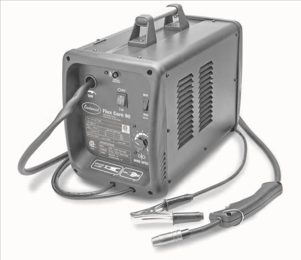
9 1 lb. Spool of 0.030" (0.8mm) Flux-Core 1 Wire Spare Contact Instruction Tip Manual COMPONENTS & CONTROLS 1 Wire Speed. 2. Control Power 3. Switch Thermal Overload 4. Indicator Voltage 5. Control Ground Cable and 6. Clamp Welding 7 Gun Nozzl. 8. e Contact 9. Tip Pressure 10Adjuster Rocker. 11Arm Drive. 12Roller Guide. 13Pipe Wire. Spindle


10 ASSEMBLY INSTALLING THE HANDLE 1. Line up the holes in the handle with the holes in the top in the welder. 2. On each screw place an included lock washer followed by a flat washer. 3. Insert each screw through the handle and into the top of the welder and tighten. FI. A G CONNECTING THE WELDER TO A POWER SOURCE The Eastwood Flux Core 90 welder requires a dedicated 120 VAC, 20 Amp, 60 Hz grounded outlet protected by a circuit breaker. Do not use on power sources that have voltages less than 105 VAC or higher than 132 VAC. If using an extension cord, use a minimum 12 AWG cord for up to 25 feet. FI. G B B1 B2 CHANGING THE DRIVE ROLLER The Eastwood Flux Core 90 comes set up and ready to use 0.030" (0.8mm) Flux-Core Wire. If 0.035" (0.9mm) wire is to be used, the drive roller needs to be adjusted. Adjust the drive roller according to the following procedure: 1. Open the top door of the welder to access the drive motor compartment. 2. Lift the Pressure Adjuster (FIG. B-B1) out of the way and move the Rocker Arm (FIG. B- B2) away from the drive roller. 3. Remove the Drive Roller Thumb Screw (FIG. B-B3) by turning it counter clockwise and pulling it away from the roller. 4. Remove the Drive Roller and view the wire sizes stamped on each side of the roller. 5. Install the Drive Roller in the orientation so that the size of the wire you are using is facing you on the side of the drive roller. 6. Reinstall the Drive Roller Thumb Screw (FIG. B-B3). 7. Put the Rocker Arm (FIG. B-B2) back in place and reset the Pressure Adjuster (FIG. B- B1). B3
 and spacer from the Wire Spool Spindle. 2.")
11 FI. G C C2 C3 C4 C1 INSTALLING THE WIRE The SPOOL Eastwood Flux Core 90 can be used with a 4 inch wire spool only. To install the wire spool follow the procedure listed below: 1. Open the door of the welder and remove the wing nut (FIG. C-C1) and spacer from the Wire Spool Spindle. 2. Slide the 4 inch Wire Spool onto the Wire Spindle and reinstall the spacer and wing nut.
12 THREADING WELDING WIRE THROUGH THE DRIVE MOTOR TO THE WELDING GUN This welder uses only self shielding flux-core wire in either 0.030" or 0.035" size (0.8 or 0.9mm). To install the welding wire follow the procedure outlined below: 1. Turn the power switch to the off position and unplug the welder from the power supply. 2. Remove the contact tip and nozzle from the end of the torch. 3. Ensure that the drive roller is installed in the proper position for the wire size being used. 4. Unlock the Pressure Adjuster (FIG. C-C2) and lift up on the Rocker Arm (FIG. C-C3). Ensure that the wire drive roller is appropriate to the welding wire size see the previous section describing the installation of the drive roller. The drive roller comes installed for 0.030" (0.8mm) wire. 5. Pull out the welding wire from the wire spool carefully. NOTE: Do not let go of the wire or the entire spool could unravel. 6. Cut off the small piece of the curved segment at the front of welding wire and straighten the welding wire approximately 3.0" long. 7. Thread the welding wire through the Guide Pipe (FIG. C-C4) and over the wire Drive Roller and into the torch hole. 8. Reattach the Rocker arm and reset the Pressure Adjuster. 9. Turn on the machine and set the wire speed to about With the gun pointed away from you and others, depress the trigger to begin feeding wire. NOTE: Watch the drive roller to see if any slipping is occurring between the roller and wire, if so, turn the machine off and tighten the Pressure Adjuster ¼ turn and test again. 11. Once the wire exits the end of the torch, install the contact tip and nozzle. Cut the wire about 1/4" from the end of the contact tip. OPERATION Your Eastwood Flux Core 90 can be used to perform a large number of different types of welds, all of which will require practice and testing before using on an actual project piece. This following welding process is just a baseline to get you started. 1. Connect your ground clamp to the work pieces that are to be welded. Make sure the ground clamp contacts are placed on a clean piece of metal free of paint, grease, rust, oils, etc. It is recommended to place your ground clamp as close to the weld area as possible. 2. Assess your weld area and make sure the welding area is also cleaned of any paint, grease, rust, oils, etc. 3. Plug in the welder and switch to the ON position. 4. Depress the Welding Gun trigger pointing the welding gun away from your body and then let go of the trigger and cut the wire back to ~1/4" stick out length. 5. Wearing your welding helmet, gloves, and long sleeve shirt and pants, put the end of the wire sticking out of the gun into the joint to be welded. 6. Position the Welding Gun so that it is perpendicular to the base metal with ~20 tilt back.
13 7. Depress the trigger to start the wire feed which starts the arc. NOTE: A push, perpendicular, or drag technique can be used to weld the pieces together. 8. Once you depress the trigger and the arc has started, you will notice a molten puddle will form; this puddle is the weld bead and will follow the motion of the Welding Gun. Watching the size of the puddle dictates how fast you should be moving with the torch. If you burn through the material you are either moving to slow or you need to set the machine to LOW voltage. If you re not penetrating the base metal you re either moving too fast or you need to set the machine to HIGH voltage. 9. Release the trigger on the Welding Gun to stop the weld. 10. After finished welding, turn off the welder.


14 TYPES OF WELD JOINTS 1. Butt Weld is a joint between two pieces that are laying in the same direction. 2. Corner Weld is a joint between two pieces that meet at or near perpendicular at their edges. 3. Edge Weld is a joint between two pieces where the edges are being joined. 4. Lap Weld is a joint between two overlapping pieces. 5. Tee Weld is a joint between two pieces where one is perpendicular to the other.
15 6. Plug Weld is a joint which joins two overlapping pieces by filling in a hole punched in the top piece.
16 Sheet Metal Welding Techniques When welding sheet metal, a different approach is taken to account for how thin the metal is and it s susceptible to warping it is. The technique most often used is called Stitch Welding and this process is described below: 1. Clean the metal to be welded of any paint, rust, oil, grease, dirt or any other contaminants that may be on the surface of the piece. 2. Secure the pieces to be welded in place using clamps. 3. Set the machine to LOW voltage and Wire Speed to Get some pieces of scrap metal of the same thickness and verify that the settings will work for the specific weld you will be making. 5. Once the settings have been fine tuned tack weld your final pieces in places and remove the clamps if they are in the way of the weld. 6. The Stitch Welding technique can now be utilized which is basically a series of tacks connecting together. To perform the technique, trigger the gun to form a tack weld and then continue to trigger the gun, making a series of connected tack welds following along the path of the weld joint. It is essential to keep moving around to spread out the heat making sure not to get one section too hot and warp the metal. 7. Once the entire weld has been completed allow the metal to cool. If necessary follow up with a flap disc to grind the weld bead flush. Heavy Gauge Metal Welding Techniques When welding heavy gauge metal, a different approach is usually taken to account for the metal thickness. This approach is described below: 1. Clean the metal to be welded of any paint, rust, oil, grease, dirt or any other contaminants that may be on the surface of the piece. 2. Secure the pieces to be welded in place using clamps. Be sure to leave a small gap between the two pieces of metal for the weld to flow into, this will result in a lower bead height which will require minimal finishing. 3. Set the machine to HIGH voltage and Wire Speed to Get some pieces of scrap metal of the same thickness and verify that the settings will work for the specific weld you will be making. 5. Once the settings have been fine-tuned, tack weld your final pieces in places and remove the clamps if they are in the way. 6. When welding heavy gauge metal there are two basic approaches to creating the weld. The first is a continuous bead with steady gun movement along the length of the joint. The second type of weld is a Stringer or Weave bead. This is accomplished by moving the torch in a circular or zig zag pattern. Either of these techniques will create strong welds but in some cases the Stringer or Weave type will create a more aesthetically appeasing weld bead. 7. Once the entire weld has been completed, allow the metal to cool. If necessary, follow up with a flap disc to grind the weld bead flush.
17 OVERLOAD PROTECTION Your Eastwood Flux Core 90 Welder is equipped with an overload breaker this device will protect your welder if the duty cycle is exceeded. If the output is exceeded, the internal breaker will trip and stop power supply to the drive motor although the fan will still run to cool the unit. If the breaker tripped resulting from an overload, the circuit breaker button under the side door of the welder will extend out. This circuit breaker must be reset manually. Before resetting the circuit breaker button allow the welder to cool for a minimum of 15 minutes. TROUBLESHOOTING Problem Cause Fix Burn Through Lack of Penetration Excessive Penetration Warping High voltage Adjust Voltage Output to low setting. Fast wire speed Adjust Wire Speed to slower setting. Slow Gun travel Increase your travel speed with the Welding Gun. Low Voltage Slow Wire Speed Fast Gun Travel Excessive Wire Stick Out Material Too Thick Poor Material Prep High Voltage Fast Wire Speed Slow Gun Travel Lack of Tack Welds No Clamping Poor Technique Adjust Voltage Output to high setting. Adjust Wire Speed to higher setting. Decrease your travel speed with the Welding Gun. Move the Contact Tip on the Welding Gun closer to the work piece to shorten the length of exposed Welding Wire. The Flux Core 90 is rated for a max. thickness of 1/8"; exceeding this will result in poor penetration. If welding heavy gauge metals, it may be necessary to increase the welding gap between the two pieces and also bevel the edges on the weld side of the pieces. Adjust Voltage Output to low setting. Adjust Wire Speed to slower setting. Increase your travel speed with the Welding Gun. Tack weld the pieces in multiple areas to keep the pieces from pulling apart. Use Welding Clamps to secure the pieces in their proper shape. To prevent warping, allow the piece to cool after welding small sections at a time. Move your welding areas around by not completing all the welding in one section at once, rather welding a
18 small amount in one area and then move to another to spread out the hear in the piece. Poor Fusion Low Voltage Slow Wire Speed Dirty Base Metal Excessive Wire Stick Out Cold Base Metal Adjust Voltage Output to high setting. Adjust Wire Speed to higher setting. Remove all paint, rust, oil, grease, dirt, or any other contaminants that may be on the surface of the piece. Move the Contact Tip on the Welding Gun closer to the work piece to shorten the length of exposed Welding Wire. If welding on a large piece, particularly cast pieces, which will absorb a lot of heat, it may be necessary to pre-heat your part with a torch.
19 ACCESSORIES CONSUMABLE PARTS # " / 0.8mm Contact Tips (5 Pack) #12210 Nozzle # " Flux-Cored Wire, 2lb., 4" Spool
Part #20279 MIG 250 WELDER ASSEMBLY & OPERATING INSTRUCTIONS
 Part #20279 MIG 250 WELDER ASSEMBLY & OPERATING INSTRUCTIONS SPECIFICATIONS POWER SUPPLY Rated Power Output No Load Voltage Power Input at Rated Output Duty Cycle 240 VAC 120 VAC 240 VAC 120 VAC 240 VAC
Part #12012 MIG 175 WELDER
 Part #12012 MIG 175 WELDER ASSEMBLY & OPERATING Instructions SPECIFICATIONS Output Amperage Range 30-175 A Maximum Output No Load Voltage 30 V DC Maximum Input Amperage 22 Amp Input Voltage 220 VAC 60
FC125 WELDER 125 FLUX CORE ONLY SUM OWNER S MANUAL
 FC125 WELDER 125 FLUX CORE ONLY SUM-900925 OWNER S MANUAL WARNING: Read carefully and understand all ASSEMBLY AND OPERATION INSTRUCTIONS before operating. Failure to follow the safety rules and other basic
PS ARC Welder Assembly & Operating Instructions
 PS07572 201210 ARC Welder Assembly & Operating Instructions READ ALL INSTRUCTIONS AND WARNINGS BEFORE USING THIS PRODUCT. This manual provides important information on proper operation & maintenance. Every
Flux-cored 125 Amp Welder Assembly & Operating Instructions
 1128762 Flux-cored 125 Amp Welder Assembly & Operating Instructions READ ALL INSTRUCTIONS AND WARNINGS BEFORE USING THIS PRODUCT. This manual provides important information on proper operation & maintenance.
Angle Grinder MODEL 9553B MODEL 9555B
 ENGLISH Angle Grinder MODEL 9553B MODEL 9555B 006649 DOUBLE INSULATION I N S T R U C T I O N M A N U A L WARNING: For your personal safety, READ and UNDERSTAND before using. SAVE THESE INSTRUCTIONS FOR
MMWM141I OWNER S MANUAL
 MMWM141I OWNER S MANUAL 2/2017 WARNING: Read carefully and understand all ASSEMBLY AND OPERATION INSTRUCTIONS before operating. Failure to follow the safety rules and other basic safety precautions may
EllisSaw.com. EllisSaw.com P.O. Box Verona, WI
 P.O. Box 9019 Verona, WI 9-019 GENERAL OPERATING & SAFETY INSTRUCTIONS * READ INSTRUCTIONS BEFORE USE * CAUTION: Disconnect power supply cord from power source when doing repair work or changing belt.
MMWMP240 OWNER S MANUAL
 MMWMP40 OWNER S MANUAL WARNING: Tig welder is only for steel and the user cannot tig weld aluminum. Read carefully and understand all ASSEMBLY AND OPERATION INSTRUCTIONS before operating. Failure to follow
MMW140 OWNER S MANUAL
 MMW40 OWNER S MANUAL WARNING: Read carefully and understand all ASSEMBLY AND OPERATION INSTRUCTIONS before operating. Failure to follow the safety rules and other basic safety precautions may result in
MIG WELDER. Metal man Industrial Welder Operating Instructions and Parts Manual MIG 135
 Heat Settings (4) To adjust output voltage/heat settings. Refer to the set up chart inside the wire feed compartment Welding Cable and MIG gun The welding wire is driven through the welding cable and MIG
MIG-100 WELDER WITH THERMAL OVERLOAD
 MIG-100 WELDER WITH THERMAL OVERLOAD Model 54878 Assembly And Operation Instructions Due to continuing improvements, actual product may differ slightly from the product described herein. 3491 Mission Oaks
FLUX-CORE WIRE FEED WELDER KIT
 model no. 058-894-4 FLUX-CORE WIRE FEED WELDER KIT IMPORTANT: Please read this manual carefully before using this welder and save it for reference. INSTRUCTION MANUAL model no. 058-894-4 RISK OF RADIATION
Agricultural Mechanics and Technology Power Tool Safety Rules
 Agricultural Mechanics and Technology Power Tool Safety Rules Name: BAND SAW Use: Cutting curves, circles and irregular shapes. 1. Use clean SHARP blades. 2. The teeth should always point DOWN. 3. Adjust
M30 SPOT WELDER INSTRUCTION MANUAL 230V 1PH.
 M30 SPOT WELDER INSTRUCTION MANUAL 230V 1PH. We have the right to improve and update the machine. The picture and the content are just for your reference. IN20808 2017 Chief Automotive Technologies CO9910.4
MIG/FLUX-CORE WIRE FEED WELDER KIT
 model no. 058-895- MIG/FLUX-CORE WIRE FEED WELDER KIT IMPORTANT: Please read this manual carefully before using this welder and save it for reference. INSTRUCTION MANUAL model no. 058-895- RISK OF RADIATION
MIG 250MGS OWNER S MANUAL
 MIG 250MGS OWNER S MANUAL 2/2016 WARNING: Read carefully and understand all ASSEMBLY AND OPERATION INSTRUCTIONS before operating. Failure to follow the safety rules and other basic safety precautions may
Operating Instructions and Parts Manual SK 140i MMIG140
 Operating Instructions and Parts Manual SK 140i MMIG140 Please read and save these instructions. Read through this owner s manual carefully before using product. Protect yourself and others by observing
Mig 140i. INVERTER MIG WELDER 140i FLUX/GAS SUM OWNER S MANUAL
 Mig 40i INVERTER MIG WELDER 40i FLUX/GAS SUM-900940 OWNER S MANUAL WARNING: Read carefully and understand all ASSEMBLY AND OPERATION INSTRUCTIONS before operating. Failure to follow the safety rules and
 GENERAL OPERATIONAL PRECAUTIONS WARNING! When using electric tools, basic safety precautions should always be followed to reduce the risk of fire, electric shock and personal injury, including the following.
MIG/Stick/TIG MP250Si LCD
 MIG/Stick/TIG MP250Si LCD 250 Amp, 230 Volt Multi-Process Welder Owner s Manual WARNING: Read carefully and understand all ASSEMBLY AND OPERATION INSTRUCTIONS before operating. Failure to follow the safety
Challenger 400. Instruction manual
 Challenger 400 Instruction manual 0349 301 097 041220 Valid for serial no. 448 DECLARATION OF CONFORMITY Murex Welding Products Ltd. Declare hereby that: Murex Challenger 400 Part No. 0349 308 110, 0349
Tube Facing Tool.
 www.swagelok.com Tube Facing Tool This manual contains important information for the safe and effective operation of the Swagelok TF72 series tube facing tool. Users should read and understand its contents
18 GAUGE ELECTRIC METAL SHEAR
 241-9895 18 GAUGE ELECTRIC METAL SHEAR Operator s Manual SAVE THIS MANUAL You will need this manual for safety instructions, operating procedures and warranty. Put it and the original sales receipt in
GENERAL OPERATIONAL PRECAUTIONS PRECAUTIONS ON USING DISC GRINDER
 GENERAL OPERATIONAL PRECAUTIONS WARNING! When using electric tools, basic safety precautions should always be followed to reduce the risk of fire, electric shock and personal injury, including the following.
However, there are some risk factors connected to welding. You should therefore read and follow the following safety instructions carefully.
 Installation Instructions for 555-81541 MIG/MMA Welder 180C Page 1 1. Introduction MIG/MMA 180 is an easy-to-use MIG welding machine suitable for both hobby and professional use. Before using or doing
ATBG280/6 Bench Grinder Bench Grinder ATBG280/6 230V-50Hz 280 Watt 150mm x 25mm Wheel size
 Bench Grinder ATBG280/6 230V-50Hz 280 Watt 150mm x 25mm Wheel size SPECIFICATIONS Model Number : ATBG280/6 Nominal Voltage Power Consumption No load speed Wheel size Weight 230Volt 50Hz 280 Watts 2880
GENERAL OPERATIONAL PRECAUTIONS
 GENERAL OPERATIONAL PRECAUTIONS WARNING! When using electric tools, basic safety precautions should always be followed to reduce the risk of fire, electric shock and personal injury, including the following.
VARIABLE SPEED WOOD LATHE
 MODEL MC1100B VARIABLE SPEED WOOD LATHE INSTRUCTION MANUAL Please read and fully understand the instructions in this manual before operation. Keep this manual safe for future reference. Version: 2015.02.02
Drill INSTRUCTION MANUAL. WARNING: For your personal safety, READ and UNDERSTAND before using. SAVE THESE INSTRUCTIONS FOR FUTURE 1 REFERENCE.
 ENGLISH (Original instructions) INSTRUCTION MANUAL Drill 6411 6412 6413 007894 DOUBLE INSULATION WARNING: For your personal safety, READ and UNDERSTAND before using. SAVE THESE INSTRUCTIONS FOR FUTURE
MIG/Stick General Safety Information. METAL MAN WORK GEAR Operating Instructions and Parts Manual
 METAL MAN WORK GEAR MIG/Stick 200 using product. Protect yourself and others by observing all safety information, warnings, and cautions. Failure to comply with instructions could result in personal injury
OPERATOR S MANUAL FOR MODEL BLADE GRINDER
 OPERATOR S MANUAL FOR MODEL 88-021 BLADE GRINDER Table of Contents Page Blade Grinder Safety and User Instructions 2 Unpacking the Grinder 5 Assembling the grinder 6 Adjusting the grinding angle 8 Adjusting
PS /8 Inch Electric Drill Assembly & Operating Instructions
 PS07216 3/8 Inch Electric Drill Assembly & Operating Instructions READ ALL INSTRUCTIONS AND WARNINGS BEFORE USING THIS PRODUCT. This manual provides important information on proper operation & maintenance.
ENGLISH (Original instructions) INSTRUCTION MANUAL. Drill DS4012 DOUBLE INSULATION. IMPORTANT: Read Before Using.
 INSTRUCTION MANUAL. Drill DS4012 DOUBLE INSULATION. IMPORTANT: Read Before Using.") ENGLISH (Original instructions) INSTRUCTION MANUAL Drill DS402 05402 DOUBLE INSULATION IMPORTANT: Read Before Using. ENGLISH (Original instructions) SPECIFICATIONS Model DS402 Capacities Steel 3 mm Wood
ENGLISH (Original instructions) INSTRUCTION MANUAL Drill DS402 05402 DOUBLE INSULATION IMPORTANT: Read Before Using. ENGLISH (Original instructions) SPECIFICATIONS Model DS402 Capacities Steel 3 mm Wood
SMAW LESSON #1: Initiating and maintaining an arc using the scratch start method
 SMAW LESSON #1: Initiating and maintaining an arc using the scratch start method OBJECTIVE: Upon completion of this lesson the learner will be able to strike and maintain an arc using SMAW on steel plate
INSTRUCTION BOOKLET AND WARRANTY INFORMATION 6 BENCH GRINDER
 INSTRUCTION BOOKLET AND WARRANTY INFORMATION 6 BENCH GRINDER Part No.: SW1250 PLEASE READ CARE AND SAFETY INSTRUCTIONS BEFORE USE SPECIFICATIONS Part No.: SW1250 Input Voltage: 240V Frequency: 50Hz Rated
GENERAL OPERATIONAL PRECAUTIONS
 GENERAL OPERATIONAL PRECAUTIONS WARNING! When using electric tools, basic safety precautions should always be followed to reduce the risk of fire, electric shock and personal injury, including the following.
90 AMP Flux Wire welder
 90 AMP Flux Wire welder 94056 Set up and Operating Instructions Distributed exclusively by Harbor Freight Tools. 3491 Mission Oaks Blvd., Camarillo, CA 93011 Visit our website at: http://www.harborfreight.com
ROTARY HAMMER OWNER'S MANUAL
 ROTARY HAMMER OWNER'S MANUAL WARNING: Read carefully and understand all INSTRUCTIONS before operating. Failure to follow the safety rules and other basic safety precautions may result in serious personal
ENGLISH (Original instructions) INSTRUCTION MANUAL. Drill DOUBLE INSULATION. IMPORTANT: Read Before Using.
 INSTRUCTION MANUAL. Drill DOUBLE INSULATION. IMPORTANT: Read Before Using.") ENGLISH (Original instructions) INSTRUCTION MANUAL Drill 64 642 643 007894 DOUBLE INSULATION IMPORTANT: Read Before Using. ENGLISH (Original instructions) SPECIFICATIONS Model 64 642 643 Capacities Steel
ENGLISH (Original instructions) INSTRUCTION MANUAL Drill 64 642 643 007894 DOUBLE INSULATION IMPORTANT: Read Before Using. ENGLISH (Original instructions) SPECIFICATIONS Model 64 642 643 Capacities Steel
OWNER S MANUAL. RFC-14, RFC-23A, RFC-23AG, RFCS-23, And RFC-23GD25A
 March 1994 Form: OM-826H Effective With Style No. KD27 OWNER S MANUAL RFC-14, RFC-23A, RFC-23AG, RFCS-23, And RFC-23GD25A Remote Foot Controls For Remote Amperage, Voltage, And Output (Contactor) Control
7th/8th Grade Industrial Tech General Safety. Give your undivided attention to the machine in which you are using.
 7th/8th Grade Industrial Tech General Safety Wood Lab Safety General Safety Always wear safety glasses. Report all injuries to the instructor. No baggy clothing or open toed shoes. Give your undivided
ATD AMP Variable Speed Reciprocating Saw Owner s Manual
 ATD-10535 7 AMP Variable Speed Reciprocating Saw Owner s Manual Manufactured in China To ATD Tools, Inc. Specifications TECHNICAL SPECIFICATIONS Voltage: 120V Frequency: 60Hz Power input: 7 Amps No load
Dust Collector. Model No: DC2200 (FM300S)
") Dust Collector Model No: DC2200 (FM300S) GENERAL SAFETY INSTRUCTIONS Before attempting to operate this machine, it is important that you read, understand and follow these instructions very carefully. They
Dust Collector Model No: DC2200 (FM300S) GENERAL SAFETY INSTRUCTIONS Before attempting to operate this machine, it is important that you read, understand and follow these instructions very carefully. They
DRILL BIT SHARPENER MODEL NO: CBS43 OPERATION & MAINTENANCE INSTRUCTIONS PART NO: LS0710
 DRILL BIT SHARPENER MODEL NO: CBS43 PART NO: 6480232 OPERATION & MAINTENANCE INSTRUCTIONS LS0710 INTRODUCTION Thank you for purchasing this CLARKE drill bit sharpener. Before attempting to use this product,
18500 PORTABLE ELECTRIC POWER DRIVE
 18500 PORTABLE ELECTRIC POWER DRIVE PRODUCT INFORMATION AND OPERATING INSTRUCTIONS: Description: Widder 18500 Portable Electric Power Drive is an electric-motor-driven, heavy-duty power drive which provides
18600 PORTABLE POWER DRIVE THREADER PRODUCT INFORMATION AND OPERATING INSTRUCTIONS:
 WIDDER TOOLS 18600 PORTABLE POWER DRIVE THREADER PRODUCT INFORMATION AND OPERATING INSTRUCTIONS: Description: The 18600 Portable Electric Threader is an electric-motor-driven, heavy-duty power drive which
3-1/4 HP VARIABLE SPEED PLUNGE ROUTER
 IMPORTANT INFORMATION 2-YEAR LIMITED WARRANTY FOR THIS PLUNGE ROUTER KING CANADA TOOLS OFFERS A 2-YEAR LIMITED WARANTY FOR NON-COMMERCIAL USE. 3-1/4 HP VARIABLE SPEED PLUNGE ROUTER PROOF OF PURCHASE Please
ENGLISH (Original instructions) INSTRUCTION MANUAL. Drill MT600 MT601 DOUBLE INSULATION. IMPORTANT: Read Before Using.
 INSTRUCTION MANUAL. Drill MT600 MT601 DOUBLE INSULATION. IMPORTANT: Read Before Using.") ENGLISH (Original instructions) INSTRUCTION MANUAL Drill MT600 MT60 003635 DOUBLE INSULATION IMPORTANT: Read Before Using. ENGLISH (Original instructions) SPECIFICATIONS Model MT600 MT60 Capacities Steel
ENGLISH (Original instructions) INSTRUCTION MANUAL Drill MT600 MT60 003635 DOUBLE INSULATION IMPORTANT: Read Before Using. ENGLISH (Original instructions) SPECIFICATIONS Model MT600 MT60 Capacities Steel
IM /2016 REV03 POWERTEC 305S, 365S, 425S, 505S
 IM3023 09/2016 REV03 POWERTEC 305S, 365S, 425S, 505S OPERATOR S MANUAL ENGLISH Lincoln Electric Bester Sp. z o.o. ul. Jana III Sobieskiego 19A, 58-263 Bielawa, Poland www.lincolnelectric.eu Declaration
Guild of Oregon Woodworkers Shop Safety Test
 Guild of Oregon Woodworkers Shop Safety Test You must pass the Test with an 80% or better and self-correct it to 100% Make sure you put the answers under the correct portion of the answer sheet for the
Operating Manual 6 Industrial Bench Grinder ATBG280/
 Operating Manual 6 Industrial Bench Grinder ATBG280/6 804531 40 Year Australian Heritage The reputable name in bench grinders for 40 years Protect yourself and others by observing all safety information,
HOT ROD 500S OPERATOR S MANUAL IM /2016 REV05 ENGLISH
 HOT ROD 500S IM3035 09/2016 REV05 OPERATOR S MANUAL ENGLISH Lincoln Electric Bester Sp. z.o.o. ul. Jana III Sobieskiego 19A, 58-263 Bielawa, Poland www.lincolnelectric.eu Declaration of conformity Lincoln
College of Forestry 610: Power Tools
 College of Forestry 610: Power Tools Safety Policy & Procedure Manual Section 600: Workshops and Shop Tools Effective: 01 January 2007 Revised: August 2014 PURPOSE The purpose of this section is to provide
Introduction to Carpentry Power Tools
 Youth Explore Trades Skills Introduction to Carpentry Power Tools Description s use power tools every day, and the ability to use these tools correctly and safely is paramount. In this Activity Plan, students
MIG 175. Item# OPERATOR S MANUAL
 Item# 164612 OPERATOR S MANUAL Read carefully and understand RULES FOR SAFE OPERATION and instructions before operating. Failure to follow the safety rules and other basic safety precautions may result
CHAPTER 52 ELECTRICAL POWER TOOLS
 CHAPTER 52 ELECTRICAL POWER TOOLS HOW TO CHOOSE AND USE THEM The Types and Uses pages provide you with a list of the electrical power tools found in the pioneer tool outfit. These pages should help you
COOL-SHIELD AUTO-DARKENING FILTER CARTRIDGE (ADF) HELMETS
 HELMETS") COOL-SHIELD AUTO-DARKENING FILTER CARTRIDGE (ADF) HELMETS IM0000 February, 2009 This manual covers equipment which is no longer in production by The Lincoln Electric Co. Specifications and availability
COOL-SHIELD AUTO-DARKENING FILTER CARTRIDGE (ADF) HELMETS IM0000 February, 2009 This manual covers equipment which is no longer in production by The Lincoln Electric Co. Specifications and availability
BB Inch Double Cut Saw Assembly & Operating Instructions READ ALL INSTRUCTIONS AND WARNINGS BEFORE USING THIS PRODUCT.
 BB07552 5 Inch Double Cut Saw Assembly & Operating Instructions READ ALL INSTRUCTIONS AND WARNINGS BEFORE USING THIS PRODUCT. This manual provides important information on proper operation & maintenance.
VARIABLE SPEED WOOD LATHE. Model DB900 INSTRUCTION MANUAL
 VARIABLE SPEED WOOD LATHE Model DB900 INSTRUCTION MANUAL 1007 TABLE OF CONTENTS SECTION...PAGE Technical data.. 1 General safety rules....1-3 Specific safety rules for wood lathe.....3 Electrical information.4
INVERTEC V145-S (MANUAL IN ENGLISH) IM /2012 Rev. 7 ENGLISH
 IM /2012 Rev. 7 ENGLISH") INVERTEC V145-S IM2001 08/2012 Rev. 7 (MANUAL IN ENGLISH) ENGLISH Lincoln Electric Bester Sp. z o.o. ul. Jana III Sobieskiego 19A, 58-263 Bielawa, Poland www.lincolnelectric.eu Declaration of conformity
INVERTEC V145-S IM2001 08/2012 Rev. 7 (MANUAL IN ENGLISH) ENGLISH Lincoln Electric Bester Sp. z o.o. ul. Jana III Sobieskiego 19A, 58-263 Bielawa, Poland www.lincolnelectric.eu Declaration of conformity
Wall Mount Dust Collector 650 CFM Instructions
 Wall Mount Dust Collector 650 CFM Instructions Effective Febuary 2018 Review full instruction manual prior to use for important safety information. Always check Rockler.com to confirm that you are using
Elcometer Muller Laboratory Grinder
 English Elcometer 2000 Muller Laboratory Grinder Operating Instructions English is a registered trademark of Elcometer Limited. All other trademarks acknowledged. Copyright Elcometer Limited. 2009. All
MEC Auto-Mate Assembly Manual. For MEC 9000G/GN and 8567 Grabber Series
 MEC Auto-Mate Assembly Manual For MEC 9000G/GN and 8567 Grabber Series Thank you We really appreciate your support of our product line. But our commitment to you hardly ends here. We won't be satisfied
The DeltaGrip System. Safety and Operating Instructions. Trigger. Air Supply Connection. Handle Assembly. Air Line Assembly.
 The DeltaGrip System Safety and Operating Instructions Trigger Air Supply Connection Handle Assembly Air Line Assembly Punch Die Pneumatic Diaphragm Assembly Shackle, Pin & Jam Nut Jaw Frame Shoulder Screw
INSTRUCTION BOOK EASILY REMOVEABLE DIES FOR YOUR BINDING NEEDS OD 4012 SHOWN WITH THE OPTIONAL PALM SWITCH FOR THE OD 4012
 RHIN- -TUFF INSTRUCTION BOOK FOR THE OD 4012 AND INTRODUCTION TO THE OD 4012 BINDING MODULES www.rhin-o-tuff.com HD 4270 OD 4300 HD 4470 HD 4171 HD 8370 PAL 14 HD 4170 PAL 14 EASILY REMOVEABLE DIES FOR
Tapping Screw (W/Flange) 46 Cord Armor 47 Tube (D) 48 Cord. 45 Cord Clip. Tapping Screw (W/Flange) 10 Gear Cover Ass'y. 12 Socket (B) Ass'y
 46 Cord Armor 47 Tube (D) 48 Cord. 45 Cord Clip. Tapping Screw (W/Flange) 10 Gear Cover Ass'y. 12 Socket (B) Ass'y") W8VB The exploded assembly drawing should be used only for authoized service center. W8VB Item No. Part time 1 Magnetic Hex. Socket 2 Sub Stopper 3 O-Ring (S-16) 4 Locator (A) 5 Lock Sleeve (A) 6 O-Ring
W8VB The exploded assembly drawing should be used only for authoized service center. W8VB Item No. Part time 1 Magnetic Hex. Socket 2 Sub Stopper 3 O-Ring (S-16) 4 Locator (A) 5 Lock Sleeve (A) 6 O-Ring
Sales and Service
 OPERATION MANUAL / SPARE PARTS LIST MANUAL SEALLESS STEEL STRAPPING TOOL MODEL A333 13.2370.01 INDEX PAGE 1 SAFETY INSTRUCTIONS 2 2 WARRANTY CONDITIONS AND LIABILITY 3 3 APPROPRIATE USE 3 4 TECNICAL DATA
Mortising Attachment
 Mortising Attachment Owner s Manual WARNING: Read carefully and understand all ASSEMBLY AND OPERATION INSTRUCTIONS before operating. Failure to follow the safety rules and other basic safety precautions
VERSAtoolTM SAE J533 & SAE J1453. Safety and Operating Manual
 VERSAtoolTM Mechanically Assisted / Manual Tube End Flare & Flange Machine SAE J533 & SAE J1453 Safety and Operating Manual I. Safety Instructions................................. Page 2 II. Specifications.....................................
INVERTEC 135S, 150S & 170S
 IM2013 04/2016 REV06 INVERTEC 135S, 150S & 170S OPERATOR S MANUAL ENGLISH Lincoln Electric Bester Sp. z o.o. ul. Jana III Sobieskiego 19A, 58-263 Bielawa, Poland www.lincolnelectric.eu I Declaration of
Impact Wrench. 19 mm (3/4 ) MODEL 6906
 MODEL 6906") Impact Wrench 9 mm (3/4 ) MODEL 6906 002290 DOUBLE INSULATION I N S T R U C T I O N M A N U A L WARNING: For your personal safety, READ and UNDERSTAND before using. SAVE THESE INSTRUCTIONS FOR FUTURE REFERENCE.
Impact Wrench 9 mm (3/4 ) MODEL 6906 002290 DOUBLE INSULATION I N S T R U C T I O N M A N U A L WARNING: For your personal safety, READ and UNDERSTAND before using. SAVE THESE INSTRUCTIONS FOR FUTURE REFERENCE.
i sburgh COMPACT BENDER ASSEMBLY INSTRUCTIONS & PROJECT IDEAS Rev 08/00
 i sburgh COMPACT BENDER 31980 ASSEMBLY INSTRUCTIONS & PROJECT IDEAS 2000 Rev 08/00 THANK YOU for choosing a HARBOR FREIGHT TOOLS product. For future reference, please complete the owner s record below:
Makerspace Student Machine Safety and Usage Manual
 Makerspace Student Machine Safety and Usage Manual Prepared by: Thiago De Oliveira (2016-2017) Queen s University Last Updated: 21 st October 2016 General Safety Rules and Guidelines 1. Wear APPROPROPRIATE
High Speed Drill MODEL WARNING: For your personal safety, READ and UNDERSTAND before using. SAVE THESE INSTRUCTIONS FOR FUTURE REFERENCE.
 ENGLISH High Speed Drill MODEL 6501 003002 DOUBLE INSULATION I N S T R U C T I O N M A N U A L WARNING: For your personal safety, READ and UNDERSTAND before using. SAVE THESE INSTRUCTIONS FOR FUTURE REFERENCE.
24" x 24" OSCILLATING SPINDLE MANUAL
 24" x 24" OSCILLATING SPINDLE MANUAL LAGUNA TOOLS 2072 Alton Parkway Irvine, California 92606 Ph: 800.234.1976 www.lagunatools.com 2018, Laguna Tools, Inc. LAGUNA and the LAGUNA Logo are the registered
INVERTEC V160-S, V160-T & V160-TP
 INVERTEC V160-S, V160-T & V160-TP OPERATOR S MANUAL IM2007 05/2016 REV06 ENGLISH Lincoln Electric Bester Sp. z o.o. ul. Jana III Sobieskiego 19A, 58-263 Bielawa, Poland www.lincolnelectric.eu Declaration
ULTRA CUTTER PRO OPERATORS INSTRUCTION MANUAL. This manual covers all models 9, 11 and 13 HP
 ULTRA CUTTER PRO OPERATORS INSTRUCTION MANUAL This manual covers all models 9, 11 and 13 HP Per OSHA 1926.503 it is the machine owner s responsibility to ensure that all workers using this Ultra Cutter
MANUAL SEALLESS STEEL STRAPPING TOOL MODEL A335
 OPERATION MANUAL / SPARE PARTS LIST MANUAL SEALLESS STEEL STRAPPING TOOL MODEL A335 13.2810.01 INDEX PAGE 1 SAFETY INSTRUCTIONS 2 2 WARRANTY CONDITIONS AND LIABILITY 3 3 APPROPRIATE USE 3 4 TECNICAL DATA
Tools Hand and Power. OSHA Office of Training and Education 1
 Tools Hand and Power 1 Hazards Workers using hand and power tools may be exposed to these hazards: objects that fall, fly, are abrasive, or splash harmful dusts, fumes, mists, vapors, and gases frayed
OPERATION AND MAINTENANCE FOR MODEL MRV050A REVERSIBLE
 OPERATION AND MAINTENANCE FOR MODEL MRV050A REVERSIBLE MANUAL AIR MOTOR 04666770 Edition 1 April, 1999 IMPORTANT SAFETY INFORMATION ENCLOSED. READ THIS MANUAL BEFORE OPERATING TOOL. FAILURE TO OBSERVE
 By Garrett Strong www.makemoneywelding.com Copyright MakeMoneyWelding.com All rights reserved. No part of this publication may be reproduced or transmitted in any form or by any means, mechanical or electronic,
INSTALLATION GUIDE MICROWAVE OVEN UPMC3084ST. MFL _00
 INSTALLATION GUIDE MICROWAVE OVEN UPMC3084ST MFL06208710_00 www.thesignaturekitchen.com YOUR SAFETY FIRST BEFORE YOU START Proper installation is the installer's responsibility! Proper installation by
ENGLISH (Original instructions) INSTRUCTION MANUAL. Hammer Drill HP1630 HP1631 DOUBLE INSULATION. IMPORTANT: Read Before Using.
 INSTRUCTION MANUAL. Hammer Drill HP1630 HP1631 DOUBLE INSULATION. IMPORTANT: Read Before Using.") ENGLISH (Original instructions) INSTRUCTION MANUAL Hammer Drill HP630 HP63 008892 DOUBLE INSULATION IMPORTANT: Read Before Using. ENGLISH (Original instructions) SPECIFICATIONS Model HP630 HP63 Concrete
ENGLISH (Original instructions) INSTRUCTION MANUAL Hammer Drill HP630 HP63 008892 DOUBLE INSULATION IMPORTANT: Read Before Using. ENGLISH (Original instructions) SPECIFICATIONS Model HP630 HP63 Concrete
SAFETY AND OPERATING MANUAL
 SAFETY AND OPERATING MANUAL 2 GENERAL POWER TOOL SAFETY WARNINGS WARNING! Read all safety warnings and all instructions. Failure to follow the warnings and instructions may result in electric shock, fire
Operator's manual. TruTool TKF 1500 (1A1), (1B1)
, (1B1)") Operator's manual TruTool TKF 1500 (1A1), (1B1) Table of contents 1 Safety 4 1.1 General safety information 4 1.2 Specific safety information for beveler 4 2 Description 6 2.1 Intended use 6 2.2 Technical
Operator's manual TruTool TKF 1500 (1A1), (1B1) Table of contents 1 Safety 4 1.1 General safety information 4 1.2 Specific safety information for beveler 4 2 Description 6 2.1 Intended use 6 2.2 Technical
Rotary Hammer HR4501C HR4510C HR4511C INSTRUCTION MANUAL
 ENGLISH INSTRUCTION MANUAL Rotary Hammer HR450C HR450C HR45C 00864 DOUBLE INSULATION WARNING: For your personal safety, READ and UNDERSTAND before using. SAVE THESE INSTRUCTIONS FOR FUTURE REFERENCE. ENGLISH
2-Speed Hammer Drill HP2000 HP2020
 2-Speed Hammer Drill HP2000 HP2020 SPECIFICATIONS Model HP2000 HP2020 Speed High Low High Low Capacities Concrete 20 mm 20 mm Steel 6.5 mm 13 mm 6.5 mm 13 mm No load speed (min 1 ) 0 2,300 0 900 2,300
ELECTRIC SLIP ROLL MACHINE. Model: ESR-1300X2.5/ESR-1300X4.5 ESR-1550X3.5/ESR-1580X2.0
 ELECTRIC SLIP ROLL MACHINE Model: ESR-1300X2.5/ESR-1300X4.5 ESR-1550X3.5/ESR-1580X2.0 Operation Manual Table of contents I MAIN SPECIFICATION...2 II SAFETY INSTRUCTIONS.. 2 III OPERATION INSTRUCTIONS..4
MANUAL PLASTIC STRAPPING TOOL MODEL P404
 OPERATION MANUAL / SPARE PARTS LIST MANUAL PLASTIC STRAPPING TOOL MODEL P404 43.0404.02 43040402.en/MAS/ 12.05 INDEX PAGE 1 SAFETY INSTRUCTIONS 2 2 TECHNICAL DATA 3 3 OPERATION ELEMENTS 4 4 ADJUSTMENT
ELECTRIC TUBE ROLLER
 41238-0000 ELECTRIC TUBE ROLLER OPERATING INSTRUCTIONS & SERVICE MANUAL Rev: A, 8/20/2007 TO REDUCE THE RISK OF INJURY AND EQUIPMENT DAMAGE USER MUST READ AND UNDERSTAND OPERATOR S MANUAL. Thomas C. Wilson,
SAFETY AND OPERATING MANUAL
 SAFETY AND OPERATING MANUAL BladeRunner X2 WX572 9 10 8 11 5 7 12 6 20 1 2 4 3 14 13 15 A2 A1 17 18 B2 B1 1 2 1 2 19 B3 3 4 2 C 1 D1 D1 C 2 1 E1 D2 1 2 E2 1 2 F G1 G1 F OFF ON G2 G3 H1 H2 I1 I2 I1 I2 J
IM /2016 REV08 INVERTEC V205, V270 & V405
 IM2006 05/2016 REV08 INVERTEC V205, V270 & V405 OPERATOR S MANUAL ENGLISH Lincoln Electric Bester Sp. z o.o. ul. Jana III Sobieskiego 19A, 58-263 Bielawa, Poland www.lincolnelectric.eu Declaration of conformity
PLATE JOINER 4 INCH. ASSEMBLY and OPERATING INSTRUCTIONS. Distributed Exclusively by Harbor Freight Tools
 PLATE JOINER 4 INCH 38437 ASSEMBLY and OPERATING INSTRUCTIONS Distributed Exclusively by Harbor Freight Tools 3491 Mission Oaks Blvd., Camarillo, CA 93011 Copyright 1998 by Harbor Freight Tools. All rights
SPEEDTEC 400S & 500S
 SPEEDTEC 400S & 500S IM3020 01/2012 Rev. 6 OPERATOR S MANUAL MANUALE OPERATIVO BEDIENUNGSANLEITUNG MANUAL DE INSTRUCCIONES MANUEL D'UTILISATION BRUKSANVISNING OG DELELISTE GEBRUIKSAANWIJZING BRUKSANVISNING
Quick Set Dovetail Jig
 Quick Set Dovetail Jig FOR HELP OR ADVISE ON THIS PRODUCT PLEASE CALL OUR CUSTOMER SERVICE HELP LINE : 01509 500359 THE MANUFACTURER RESERVES THE RIGHT TO ALTER THE DESIGN OR SPECIFICATION TO THIS PRODUCT
OPERATOR S MANUAL DRILLING MACHINE WITH ELECTROMAGNETIC BASE
 OPERATOR S MANUAL DRILLING MACHINE WITH ELECTROMAGNETIC BASE UNIT 30 NEWHALLHEY BUSINESS PARK, NEWHALLHEY RD, RAWTENSTALL, ROSSENDALE, LANCASHIRE BB4 6HR Tel. +44 1706 229490, fax. +44 1706 830496 www.jeiuk.com
Northern Industrial Welding Operating Instructions and Parts Manual
 Northern Industrial Welding Please read and save these instructions. Read through this owner s manual carefully before using product. Protect yourself and others by observing all safety information, warnings,
MANUAL SEALLESS STEEL STRAPPING TOOL MODEL A332
 OPERATION MANUAL / SPARE PARTS LIST MANUAL SEALLESS STEEL STRAPPING TOOL MODEL A332 13.2250.01 INDEX PAGE 1 SAFETY INSTRUCTIONS 2 2 WARRANTY CONDITIONS AND LIABILITY 3 3 APPROPRIATE USE 3 4 TECNICAL DATA
COJSAWBX Electric Jig Saw Assembly & Operating Instructions
 COJSAWBX Electric Jig Saw Assembly & Operating Instructions READ ALL INSTRUCTIONS AND WARNINGS BEFORE USING THIS PRODUCT. This manual provides important information on proper operation and maintenance.