THE ENGINEER S DESIGN MANUAL PART 1 ABSORBING POLYMER LASER WELDING
|
|
|
- Randell Evan Murphy
- 5 years ago
- Views:
Transcription


1 THE ENGINEER S DESIGN MANUAL for LASER PLASTIC WELDING PART 1 ABSORBING POLYMER LASER WELDING

2 TABLE OF CONTENTS TABLE OF CONTENTS Introduction Page 3 Overview of Traditional Joining Technologies Page 4 Advantages of Laser Plastic Welding Page 5 APLW Method Page 6 The 4 Pillars Pages 7-11 Materials Page Joint Design Pages Clamping Technology Pages Beam Properties and Delivery Pages General Design Guidelines Pages Common Pitfalls Page 34 Typical Project Roadmap Page 34 FAQ Page 35 Material Matrix Page 36
3 INTRODUCTION THE GOAL OF THIS MANUAL The goal of this Design Manual is to educate designers and engineers on through-transmission laser welding technology, give them the keys to design their products for the Laser Plastic Welding method, and to disseminate general knowledge about this technology in an unbiased approach. This manual is Part 1 of a 2 Part series: Part 1 Absorptive Polymer Laser Welding (APLW) and Part 2 Transparent Polymer Laser Welding (TPLW). The two technologies are somewhat similar but have enough differences to create the need for a separate approach. It is highly recommended to read through the APLW manual before moving onto the TPLW manual as only the differences in the TPLW method will be covered. IMPORTANT please keep in mind this is purely a set of guidelines. Every application will require its own, nuanced approach and some or all of your application s requirements may fall outside of the scope of this guide. Before you make any design adaptations or changes to mold tooling, etc., I highly recommend you consult a laser welding expert for a complete review of your application design and production needs. You can find out more about this service here: To your success, Dax Hamilton Laser Polymer Welding Expert info@daxham.com


4 OVERVIEW OF TRADITIONAL JOINING TECHNOLOGIES While Laser Polymer (Plastic) Welding really isn t a new technology, it is still not quite as well-known or widely adopted as legacy joining solutions, such as gluing, fasteners, snap fits, and ultrasonic welding. It is interesting to note that the German automotive industry was one of the first to adopt this technology around 19 years ago. In spite of the fact that it was and still is a revolutionary technology, it took many years for other industries to adopt it. While traditional methods have their place, it is a good idea to look at how implementing laser plastic welding could be beneficial and overcome some of the highlighted issues. The below list is only a few of the most common methods that laser welding has its advantages over: SNAP FEATURES Require complex injection mold tooling Extra space is typically required in the part. FASTENERS Require added cost Creates extra, superfluous features in part GLUE Messy and difficult to automate Lacks precision Often requires lengthy drying periods ULTRASONIC WELDING Significant rate of damage Not good for sensitive electronics Potential to mar visible surfaces
5 With that said, if the current joining technology is working well for the application and there are no specific issues that are prevalent, then laser welding may not be the best approach due to the relatively high cost to implement it over one of the traditional bonding methods. As system builders become more advanced, the cost to implement will go down. ADVANTAGES OF LASER POLYMER WELDING Laser Polymer Welding delivers the following advantages (among others of course): Precise control of the welding area Aesthetically pleasing weld seams visually OK on class A surfaces Ability to hold tighter tolerances in the joining process No damage to surrounding materials or sensitive electronics A perfectly hygienic method of bonding no particulates generated Ability to miniaturize designs Joining of 3D and complex shapes Removal of costly and cumbersome part features Eliminate consumables fasteners, glue, etc. Drastically improve quality Bonding strength virtually as strong as the base material Lower total cost of ownership thinking holistically Laser Polymer Welding picks up where other joining technologies leave off If there is a need to eliminate quality problems and miniaturize designs, all while avoiding damage to sensitive electronics then Laser Polymer Welding is the right choice for your design!


6 APLW METHOD: ABSORPTIVE POLYMER LASER WELDING There are several terms that have been coined for this subject to-date; laser plastic welding, plastic laser welding, through transmission welding, laser transmission welding, and laser polymer welding, (which will all be referred to synonymously throughout this manual), however, the main concept is the same A method of joining two plastics by subsequent transmission and absorption of laser energy. Another way to describe it: laser plastic welding is a cutting-edge means of joining two thermoplastics together via a laser beam in the near-infrared spectrum. In the case that two plastics are clamped tightly together, the laser beam penetrates the upper layer and is absorbed by the lower layer which in turn is heated by the laser energy and transfers this heat to the upper layer which results in both of the plastics melting and mixing to form a bond that is virtually as strong as the base material.


7 HOW IT WORKS When two plastics are clamped tightly together, a laser beam in the 1000nm range penetrates the upper layer and is absorbed by the lower layer which in turn is heated by the laser energy and transfers this heat to the upper layer resulting in both of the plastics melting and mixing to form a bond that is virtually as strong as the base material. THE 4 PILLARS OF APLW There are four, main guiding principles to this method of laser plastic welding. While many other design and engineering factors can affect the ability to laser weld a component, these four pillars are absolute requirements for all laser plastic welded applications.
8 PILLAR #1 IR TRANSPARENT UPPER LAYER The first layer of material that the laser beam shines through (IR Transparent Layer) must allow a certain portion of the laser energy to pass through. It is widely recommended that at the very least, about 5% of this energy passes through to be able to effectively heat the lower absorbing layer before degradation or burning occurs in the IR Transparent Layer. Pro Tip: To provide the widest flexibility in weld parameters and therefore ease of success a transmission rate of at least 5% is recommended. However, it is possible to go as low as 1% in certain circumstances. There have been some applications where less than 1% of the energy passes through but special welding parameters need to be used in order to create a stable process and avoid any surface degradation or burning. Of course, there are various misconceptions about the term transmissive and/or transparent when it concerns laser plastic welding. The first is that the material does not have to be clear or transparent to the human eye, it just needs to pass the respective wavelength of the laser. Most consumer electronics devices and automotive components don t employ the luxury of having a clear transparent layer and need to be opaque in whatever color the designer/stylist/marketer selects. In most common laser polymer welding applications, the wavelength used is around 980nm, (1 micron) which is supplied by a solid state semiconductor diode laser source.

9 PILLAR #2 IR ABSORBING LOWER LAYER The absorbing layer of plastic serves as the most important layer of the two. This is because the inception of the welding process happens at this layer. As the laser contacts this layer, the plastic heats up to the point where this heat is transferred to the upper layer and both plastics melt and mix as long as there is tight mechanical contact between the two. Part of this is due to thermal expansion of both plastics as they heat and expand into each other, ensuring a good mixing of the materials at the joint interface. In order for the process to work, the absorbing layer needs to be doped with a compound that absorbs the infrared laser energy. The most common dopant is carbon black, and is doped in at 0.5% - 1% by volume depending on the base resin as well as joint geometry. It is cheap and easy to come by but the resulting plastic in most cases is either grey or black. Titanium dioxide is also used in conjunction with carbon black when colors other than black or grey are desired. Certain pigments can be added with the right mixtures of TIO2 and carbon black to be able to get virtually any color desired. If a translucent absorbing layer is required, there are a couple of different suppliers of a compound which is doped into the plastic and absorbs the infrared energy but still allows the plastic to be somewhat clear (translucent). BASF has a product called Lumogen and Crystalyn has a product called Clearweld, both of which have a greenish hue which might be a prohibitive factor for some. There is also a product that is virtually clear when doped into the base resin, from a supplier called Brilliance Laser Inks.


10 PILLAR #3 TIGHT MECHANICAL CONTACT Tight mechanical contact between the parts that are to be welded is probably the most critical factor when it concerns getting a good and stable process. The importance of clamping cannot be stressed enough. It is vital to select the correct clamping style for the design of the part, whether it be a glass plate, all-metal clamping mask, or a combination of the two. The part itself needs to be able to handle the resulting forces applied while clamping to avoid issues with deflection which may result in sporadic un-welded areas along the weld seam. In some cases, a thin transparent silicone sheet in between the part and the clamping fixture will mitigate any nonplanar surfaces and allow for full contact between the two pieces. The fixture or part nest is also a key item in the package as the fixture needs to provide rigidity under the part to allow proper transfer of clamping forces through the part to the fixture. It is absolutely essential that the fixture contacts the underside of the part in all areas where there is a weld seam. PILLAR #4 MATERIAL COMPATIBILITY In general, like thermoplastics weld very well to themselves and there shouldn t be any issues with weldability in this case. Most laser plastic welding applications are able to use like materials. However, there are cases that call for two different materials to be welded together.
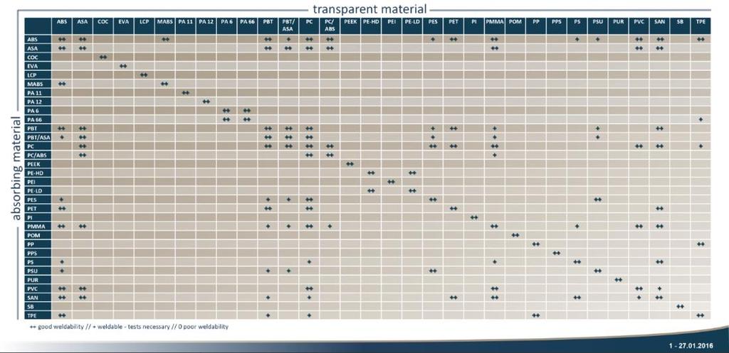
11 Whether it be for mechanical reasons, biocompatibility, structural, etc., when welding dissimilar materials to each other, two factors need to be considered: CHEMICAL COMPATIBILITY The first factor is that the two plastics need to have relatively similar chemical compatibility (surface energy and polymer chains). For example, silicone is not going to weld to polycarbonate as their chemical compatibility is just too different, let alone their melt temperatures. PROCESS WINDOW (MELT TEMPERATURE OVERLAP) The next factor is the process window of the plastic. This process window needs to have at least a 50 deg C overlap with the process window of the other plastic you intend to weld. To clarify this, there is a point at which the plastic begins to melt called the glass transition temperature, and then a point at which the plastic degrades or decomposes. The goal here is when selecting the materials, the two plastics have a 50 Deg C process window overlap in order to sustain a good and stable process. The greater the process window overlap the more stable the process will be. MATERIALS Selecting the proper materials for your project can be a daunting task and there are many factors to consider with respect to laser plastic welding. In most cases however, it is recommended to test the desired materials for their relative weldability before continuing with full part design. As mentioned before, like thermoplastics will typically weld well to each other. The Material Matrix chart will show the weldability of some common dissimilar materials but it is best to obtain actual sample coupons and test them in the lab to verify compatibility.


12 The masterbatch and compound suppliers can produce resin grades that are laser welding compatible for both the transparent and absorbing component, as well as color-matched to your specific application. Some are listed below for you: RTP Company A. Schulman PolyOne Clariant COLOR MATCHING Virtually any color combination can be set up to work for laser plastic welding. Companies such as the ones listed above can help you dial in your color preferences to be absorbing to the laser as well as transmissive. Even black to black and white to white are possible. Please keep in mind that IR Transparent dyes or pigments are not recommended for semi-crystalline materials such as PEEK or LCP. These materials should only be used in their natural state (IR Transparent layer only). Glass fills (beads or fibers) also drastically reduce the transmissive properties of the material. For example, PBT can have up to 30% glass fill, however, the transparent layer shouldn t be thicker than about 2mm. One thing to note is that with this material in particular, injection mold temperatures have a drastic effect on the transmissivity (such as cooling too fast or too slow, etc.) If you are specifying a grade of polyamide (Nylon), no more than about 30% GF should be used. Orient Corporation Black to Black If an IR transparent black or other color is desired in a glass filled part, the transmissivity will need to be checked as the dye + the glass fills drastically reduce the transmissivity. Again, semi crystalline materials should not be dyed or pigmented.

13 ADDITIVE SELECTION CHART Reference the below chart when selecting additives AMORPHOUS SEMI-CRYSTALLINE MATERIAL STATE LASER WELDABLE? MATERIAL STATE LASER WELDABLE? NATURAL YES NATURAL YES CLEAR YES CLEAR YES GLASS FILL <40% GLASS FILL <20% DYES OR PIGMENTS YES, MINIMUM 3% LET DYES OR PIGMENTS NO OTHER ADDITIVES <5% LOADING OTHER ADDITIVES NO MATERIAL COMPATIBILITY CHART Please refer to the appendix of this document for a larger version of this chart or visit:
14 JOINT DESIGN The first step in designing for laser plastic welding is to identify what major constraints you have in developing your product. Asking the below questions can help with the design process: Are you locked into certain types of material considerations such as biocompatibility or structural? Does the product you are designing have to withstand a certain mechanical fatigue or pressure? Is your product highly visual, or perhaps the colors or styling are dictated by the marketing team? Are there UV or other material properties that will influence the mechanical structure and selection of materials? It is important to answer these questions before venturing down the path of joint design for laser plastic welding as you could end up backing yourself into a corner quite easily. Lap Joint Sacrificial Rib Butt Joint Radial Style Typical Joint Profiles for Plastics Bonding

15 DESIGNING FOR STRENGTH The first subject this design guide will tackle is designing for strength. When the main object is to design for mechanical integrity and strength of the part, this will trump most of the visual criteria. Mechanical design considerations: Structural Thick absorbing and transparent layer, relatively wide (>2mm) side walls, ribs or other stiffening features in both the absorbing and transparent layers Leak integrity Does the part need to pass a standard such as the IP66 salt spray or other harsh environment testing? Burst Pressure Is a specific burst pressure necessary for hermetic integrity? What forces are acting on the part? Burst, chemical, thermal cycling, etc. Where is the part seam or joining line going to be? Is melt flash going to be an issue if it protrudes outside the edges of the part? Typically with large welding ribs and a large amount of collapse during welding, there tends to be some flash that will be visible after welding. It is recommended to use as wide of a sacrificial rib as possible without giving up wall thickness of the housing For Example: 100mm x 75mm housing to lid application requiring an IP rated tightness specification, and a flash hiding feature A recommended design form factor could be a 2mm-3mm wide sacrificial rib with mm of collapse during the welding process to ensure a good connection and material transfer between both joining partners. Cross-Section of Standard Sacrificial Rib and Flash Hiding Feature

16 AESTHETIC DESIGN CONSIDERATIONS Once strength and integrity have been considered we can then turn our attention to the visual form and looks of the component. Some things to consider: Actual Laser Plastic Welded Car Taillight Image courtesy of Motortrend Color selections are my parts required to meet a color matching standard? 3D profile of part is there some contour that I cannot deviate from such as radii in the potential weld area? Geometry of the weld seam Are sink marks OK? Sometimes sink marks occur after the welding process that are visible to the trained eye. Coatings, paint, etc? Are there any coatings that get applied either before or after the laser welding process? Damage to part during clamping could there be potential for parts to get scratched or blemished in some way during clamping? Hide the flash or excess material is there a visual requirement for the part to hide or eliminate any excess material ooze or flash from the outside environment? Sometimes both aesthetic and structural properties must be considered and compromises between the two will have to be made. JOINT PROFILES When designing a part for laser plastic welding, the designer must decide if a sacrificial welding rib is needed or not. If so, special care must be taken when including this feature. You can compare the sacrificial rib to that of the energy director for those of you familiar with ultrasonic welding, with the exception that the rib needs to be flat at the top instead of pointed. There are many different ways to design the joint for optimal process.


 When joining flat to flat parts, no sacrificial rib is needed, or in some special cases a much")
17 The first thing to take into consideration when selecting a joint profile is to fully understand if the goal is structural or aesthetic. If the part needs to withstand a certain burst pressure or has structural demands such as an actuator or electromechanical device, in almost every case, a weld rib is needed to overcome any variations from the injection molding process and ensure a good, strong, and hermetic bond. This is especially true with parts that have a complex labyrinth of fluid channels. FLAT-TO-FLAT (LAP JOINT) When joining flat to flat parts, no sacrificial rib is needed, or in some special cases a much smaller rib can be designed into the absorbing part 0.1mm or less. Lap Joint Examples Small Rib Sometimes Used in Microfluidic Devices


 HIDING FLASH There are certain features")
18 RADIAL WELD INTERFERENCE FIT When designing for a radial style weld interface, typically just a good interference fit will suffice. A 1%-2% interference fit on diameter should be a good rule of thumb to start with. For example, a 10mm diameter round part should have 0.01mm-0.02mm of interference to get a good weld. NO BUTT JOINTS! With APLW, butt joints do not work. This is due to clamping constraints but most importantly due to the absorbing layer degrading under laser energy before transferring any usable heat to the transparent layer. Further, two absorbing layers would not work because there is no way to ensure a good transfer of material after heating between the two, referring to APLW, with clamping and subsequent heat transfer. Radial Joint Cross Section In certain cases, if you have two absorbing resins, butt welding is possible (see image at right, courtesy of Orient Corporation) HIDING FLASH There are certain features that can be designed into the part on the transparent layer to hide any excess melted material or flash that is a result of the welding process. The most common is to add a flange that shields the welding area from view. See below: Butt Welding Example Courtesy of Orient Corporation Flash Hiding Feature Examples
19 CLAMPING TECHNOLOGY Clamping and contact of the two parts to be joined is a vast area with many facets and is by far the most important aspect of laser plastic welding. Clamping will have far reaching effects on your process both in development as well as in high-volume production. The goal of clamping in laser plastic welding is to provide a tight mechanical connection ensuring contact between the two components that are to be joined, thus eliminating any potential gaps. As mentioned before, one of the 4 pillars of Laser Plastic Welding is a tight mechanical connection. Without the parts being clamped tightly together, the laser energy would burn and degrade the absorbing layer before it transferred the heat to the upper transparent layer. Clamping is everything in laser plastic welding, it will make or break your process, every time and needs serious consideration. The part must be able to handle the mechanical force that is transferred by the clamping system. If not designed properly, warping will occur resulting in an imperfect weld seam. An important point to consider when selecting a clamping method is that anything in between the laser aperture (F-Theta lens, Beam Expander, Diffractive Optic) and the welding surface (glass or plastic) has a tendency to attract impurities from the air which settle on the surface and superheat and burn when hit by the laser. This causes micro fractures on the surface which gradually decreases the amount of laser energy that gets through. With that being said, there are several different clamping methods known to laser plastic welding and each have their advantages and disadvantages.

20 WINDOW CLAMP TOOLING The first clamping technology is also the most simple. It is mainly used for prototyping in a lab scenario. It involves the use of a flat piece of clear acrylic PMMA, PC, or glass to exert mechanical force on the surface of the part to be welded. Laser access is, for the most part, unobstructed and this concept makes for a great and inexpensive means of testing parts in the lab and even in some limited batch run scenarios. If using plastic, it can also be easily machined to conform to the part surface anomalies whether it be 3D contours or other features. Window Clamping Tool Example - Cross Section Glass can also be used in clamping. Quartz glass is machinable with diamond coated tools and borosilicate glass is typically ground to shape and in certain cases this can provide a cost-effective, limited-life production solution. You could expect to get around parts with each new piece of glass if you have a good preventative maintenance (cleaning) schedule. In the case where glass is used, certain coatings can also be applied to limit back-reflection and aid in the laser transmission.


21 ALL METAL CLAMPING OUTER ONLY The next type of clamping involves using an all metal outer clamping mask which contacts between 0.5mm and 1mm of the outer perimeter of the part to be welded. Typically these types of clamps are made from tool steel or stainless steel. Metal Outer Clamping Tool Example - Cross Section For a production scenario, this clamping method is a step up from having an acrylic or glass clamp in-between the laser and the welding surface that can potentially be contaminated. However, the drawback of this type of clamping method is that as the plastic heats up, it tends to warp and since the clamp is only on the perimeter of the part, the inner area of the part stays put and the outer perimeter where the clamp contacts, moves down and warps the edges, see illustration below: Image Courtesy of:

22 HYBRID TOOLING The next clamping technology is a somewhat of a hybrid between full production tooling and prototype tooling. It consists of mounting an inner metal clamping mask and an outer metal clamping mask to a piece of clear PMMA or PC. This leaves a channel that is open for the laser to pass through. This acts as a sort of hybrid production clamping technology. While the warping issues of the outer profile metal clamp are overcome, there is still the surface for dust to settle and become burned by the laser. This type of clamping is best suited for ramp up prototype runs where the intent is to go into production with the part but a low-cost upfront tooling investment is desired. Later a full metal production clamping device can be developed. Hybrid Clamping Tool Example - Cross Section

23 ALL METAL CLAMPING DEVICE Finally, we have what is widely considered as the best means of clamping for a maintenance free production scenario. It utilizes thin metal ribs to connect metal inner and outer stamps so that there is no medium for the laser to be obstructed by. This type of clamping negates all of the issues pertaining to deformation of the sides and lid portion of the part as well as any particulates settling on glass or plastic surfaces. All Metal Clamping Tool Example There is virtually no maintenance necessary with this type of tooling and it is a good option for high volume manufacturing. The most common question surrounding the this type of tool is: Will the laser be shadowed by the metal ribs? The answer is: Yes, to a degree it is, however, there are a couple of factors that minimize any potential shadowing effect that may occur. The first is what is sometimes called beam wrapping. Beam wrapping is the effect where the laser sort of wraps itself around the metal rib and the majority of the laser beam surface area is transmitted to the part, see image on the following page.


24 Beam Wrapping - Illustration The next factor is similar to what happens when TIG welding metal, the object is to push the molten bead along during the welding process with the TIG torch. This also happens while welding plastics, the molten plastic is pushed under the metal rib as the beam is guided around the profile of the weld path especially when using the quasi-simultaneous welding technique, where the beam is directed around the weld path many times in a short period of time. These factors combined with some optimization of the weld parameters will virtually eliminate any effect of shadowing caused by the metal rib in the laser path. TIG Welding Bead Image courtesy of: CLAMPING FORCE A very important point to consider is that the parts must be structurally sound enough to handle the forces being applied and transmitted through the part during clamping. The typical range of clamping force applied is between 2-3 Newtons per square millimeter of welding joint surface area.
25 This is good place to start when doing your structural analysis. Good support is needed directly under the weld joint both in the part itself as well as the fixture the part is placed in for the welding process. Proper support will ensure minimal warping or bowing of internal features and thus resulting in an inconsistent welding seam. This is one of the most important aspects to laser plastic welding and is often overlooked when designing for this technology. Pro Tip: A layer of silicone sheet (1mm thick or so) can be applied in between the glass or plastic clamping window when welding large complex patterned welds (2D only). This helps overcome any warping issues and allows for an even clamping force over the whole surface of the part. The same silicon layer can be added to the part nest to allow for free-alignment. APPLICATIONS OF EACH TYPE OF TOOLING Quick prototyping of sample coupons and flat surfaced parts Acrylic or glass upper clamp Universal part nest modular fixture Prototyping of most parts contoured surface or not Acrylic or glass upper clamp Custom machined part nest or 3D printed Prototyping and multi part runs Hybrid upper clamp Custom machined part nest Production All metal style upper clamp Custom machined part nest 1940nm welding (Transparent Polymer) Borosilicate glass upper clamp Custom machined part nest Radial welding Use mirror tooling Fixturing either in rotary device or nested


26 BEAM PROPERTIES AND DELIVERY Several optical components work together in a laser plastic welding system to form and focus the laser beam. With that result, there are 4 different methods of beam delivery and ways to get the laser to the part. They are summarized below. CONTOUR WELDING Method of beam delivery utilizing a galvanometer scanning unit, or CNC control, where the laser is directed along a programmed 2D (X and Y axis) welding path one time with enough energy to heat the materials and properly weld at the joint interface. There is no collapse or movement of the transparent part. This method is feasible for flat to flat (lap joint) style parts where an energy director is not required. 3D CONTOUR Method of beam delivery where the laser is directed along a programmed 3D (X, Y, and Z axis) welding path one time with enough energy to heat the materials and properly weld at the joint interface. This can be achieved by either using a multi-axis robotic arm to move the laser along the path, by means of a 3D galvanometer scanning unit, or even CNC motion control. (A car taillight is a good example of this.) Contour Welding Concept In some cases, a 2D galvanometer scanning unit can be used if certain guidelines are met. This type of beam delivery method is used on larger free-form curved parts where geometry would inhibit the beam access. QUASI-SIMULTANEOUS Method of beam delivery utilizing a galvanometer scanning unit similar to Contour Welding except that the laser is directed along the programmed 2D path at a high rate of speed, enough times to achieve a preset collapse or melting travel distance of the transparent part. This simulates the entire weld profile being lased simultaneously. QS Welding Concept

27 When a welding rib or energy director is needed, this is the only type of beam delivery that can be used aside from simultaneous. The reason for this is that as one section of the part begins to heat enough to start melting, the clamping mechanism cannot collapse that area because the remaining majority of the part is not melted and will not allow the clamp to travel downward in the Z direction. SIMULTANEOUS This is a method where the laser energy is delivered by multiple optical fibers placed strategically around the profile to be welded. To ensure a homogenous blending of the individual fibers, the laser energy projecting from the fibers is diffused by means of wave guide to the welding surface of the part. SHAPED BEAM DIFFRACTIVE OPTICAL ELEMENT The laser can be focused into certain shapes or profiles by means of a Diffractive Optical Element to allow a more efficient coverage of the welding area. This is achieved by means of precision optics such as prisms, lenses, light guides, etc. DOE s are now being used to create a top hat profile which greatly decreases burning potential in low transmissive materials. Simultaneous Welding Concept MIRRORS AND BEAM GUIDANCE The laser beam itself is a very interesting phenomena in that it can be directed, channeled, focused and guided to a precise position, in a perfectly repeatable manner. In the event where features on a part cannot be accessed by conventional means, IE (2D scanner, 3D scanner, CNC motion control, or robot, etc) then precisely placed mirrors can be used to direct the beam to access that particular feature.

28 CONICAL MIRRORS FOR RADIAL WELDS Mirrors also make a great, robust, and quick way to weld around a circular part in a radial style weld joint. The mirror would be in a conical shape and a conventional 2D scanner could be used to direct the beam around the conic and eventually mirrored to the part. This works well for radial welding applications. When welding round contoured parts or radial style weld joints, the use of mirrors in conjunction with clamping and fixturing can be very valuable. Radial Style Welding With Mirror RADIAL WELD TOOLING When it comes to radial welds the clamping force is provided not by tooling, but actually the interference fit designed into the parts themselves. Radial welds can be done in 2 different ways, 1. parts held horizontal and mechanically spun while the laser is held stationary, as seen below 2. the parts are fixtured vertically and a conical mirror, acting like a collar around the part, is used to direct the laser around the joining area. DIRECTED MIRRORS FOR WELDING UNDER OBSTRUCTIONS In certain cases, parts may have features that restrict laser access from the top, shadow the beam path, or even obstruct it completely. In these instances, mirrors with particular shapes and strategically placed, can be used to direct the beam around or even under such obstructions.

29 GENERAL GUIDELINES UNIFORM LID THICKNESS It is recommended that the transparent layer is of uniform thickness around the profile of the weld joint. If multiple or varying thicknesses are used, the chance for varied laser power at the welding surface is increased, which can cause an unstable process. Granted, there is some level of programmable control at specific areas around the weld profile that can alleviate some of these affects, however, it is best to keep thicknesses uniform. MINIMUM POSSIBLE THICKNESS As the thickness of the transmissive layer increases, the less the percentage of laser energy gets through. It is recommended that the transmissive layer stays as thin as possible taking into consideration injection molding constraints as well as structural needs. Typical thickness of the transmissive layer is between 1mm-3mm. If additives such as glass fills are used or IR transparent pigments, this greatly reduces the amount of laser energy able to pass through the part and therefore reduces the thickness this layer can be.
30 Rayleigh Length Focal plane/beam waist UNIFORM JOINT WIDTH It is required in laser plastic welding that the width of the welding rib around the part stay uniform. This means no dimensional changes or variation. All sharp corners must be filleted so that the rib width stays uniform. The laser beam must overlap the welding joint by a minimum of 0.5mm on either side. If the joint width was to vary or get wider, the laser would potentially not be able to fully melt the plastic in one pass. The same holds true for sharp corners. PLANAR JOINTS It is highly recommended that the welding profile lies on a single plane. When design or styling requirements demand a profiled or curved surface and resulting weld joint, certain criteria must be taken into consideration which will be covered later in this guide. RAYLEIGH LENGTH AND MAXIMUM DEVIATION Since the beam is in the shape of an hourglass when focused, there exists a certain region at the center of the beam waist which is called the Rayleigh length. Inside of this area the laser beam is effectively still focused enough to properly weld. This can to certain extents allow some 3D or non-planar welding. In optics and especially laser science, the Rayleigh length or Rayleigh range is the distance along the propagation direction of a beam from the waist to the place where the area of the cross section is doubled. (source: Wikipedia)


31 CURVED UPPER SURFACES AND REFRACTION/REFLECTION When welding 3D or non-planar parts, too aggressive of a radius or curve will act as a mirror and the laser will not penetrate due to redirection of the light think of the spoon in a glass of water optical effect. Reflection Effect Image For Reference Only Refraction Example MUCH TIGHTER CONTROL OF INJECTION MOLD TOLERANCES One critical item to consider when implementing laser plastic welding is the need for much tighter control of the injection molding process. This means that tolerances need to get smaller! It is recommended that the tolerance stack up is no greater than 0.2mm for flatness. Dimensionally the parts can vary a bit but no greater than about 0.5mm. Gaps between the two pieces need to be less than 0.1mm in order to create a stable welding process.
32 NO EJECTOR PIN MARKS OR GATES IN WELD AREAS It is recommended that no marks reside in the area where the welding is to take place. This includes material gates, ejector pin marks, injection mold slide marks and other surface irregularities. Some of these instances are unavoidable and should therefore be relocated to another area where they wont interfere with the welding. The main thing is that there are no gaps between the parts caused by these surface irregularities, which will cause burning in the welding area and not allow heat transfer and the two plastics to join properly. CENTERING FEATURES IN PART It is important to design certain features into the transparent part that will locate it to the absorbing side. This will help the two parts locate to each other and avoid misalignment. Centering features will also help to keep the transparent part on the absorbing part during the manufacturing process. Sometimes during the part-transfer step in a fully automated production line, the parts could shift and separate from each other before welding can occur. This technique can also be designed into the welding joint itself.


 Figure out the maximum")
33 BEAM ANGLES AND REFRACTION When designing for laser plastic welding, care must be taken if a part has features that protrude off of the welding plane. This includes bosses and other features that could potentially shadow the laser and keep it from reaching the welding area. In addition to beam shadowing, one must take into consideration the angle of incidence of the laser. See diagram below. This will vary with the type of laser and optics and is a result of the distance between the focal plane of the laser and the aperture or F Theta lens as well as the size of the scan field. This can be calculated with some simple trig or in the CAD system using the below concept. CALCULATE ANGLE OF INCIDENCE The angle of incidence is calculated with the following steps: Figure out the focal height of the laser beam (Use F-Theta specification) Figure out the maximum dimensions of the part Solve for angle of incidence Calculating the angle of incidence allows for figuring out the draft necessary and positioning for protruding part features. It is also necessary when designing inner-stamp tooling or all metal style tooling to calculate the draft allowing for laser clearance.
34 COMMON PITFALLS By following the recommendations in this guide you will avoid most problems with laser plastic welding, however, here is a list of common pitfalls to avoid: Non compatible or non weldable material selection Poorly transmissive upper layer fills (glass, TIO2) or dyes, etc. Bad injection molded components loose tolerances Parts deform under clamping pressure Internal part features obstructing welding collapse Internal/external features refracting beam 3D surfaces refracting laser A TYPICAL PROJECT ROADMAP Phase 1 q Select materials verify OK q Joint design recommendation (this typically takes 2-3 iterations) q Proto tooling concept Phase 2 q Sample coupons test welded in lab q Proto tooling designed and built q Proto welding and DOE (typically less than 200 parts) q Lock in materials and joint design q Research laser welding system supplier that is best suited for the application Phase 3 q Purchase system and production tooling q Supplier acceptance testing of production system q Installation and commissioning at manufacturing site q Ramp up of production line q Follow up service and support
35 FREQUENTLY ASKED QUESTIONS Can I use my existing joint geometry, for example Ultrasonic welding? No, because the apex of the triangular energy director used in US welding will tend to burn first before effectively transferring the heat needed to melt the opposing layer of plastic. A new joint profile is needed and consists of a flat top profile as pictured earlier in this design guide. How can I inspect my laser plastic welded component for joint integrity? By using an Infrared inspection system either integrated into the welding process or in a standalone form factor. An IR inspection system specifically set up for inspecting plastic welded components can see thru the laser transparent layer and effectively analyze the bonding area with special software. More info at: Will the laser damage the plastic or components inside or outside of the welding rib area? No, this is one of the major advantages of laser plastic welding, LPW has a very small heat affected zone and since the beam is precisely controlled, it stays within the set boundary. What is the maximum thickness the transparent layer can be? The transparent layer should be as thin as possible, however, when structural cases or other design constraints present themselves, the maximum thickness depends ultimately on the transmissiity of the material. For example, in a clear PC, the thickness can be up to about 10mm and still weld just fine. Can you weld opaque plastics? Yes, as long as the plastic transmits the laser energy in the appropriate wavelength. RTP Company and others can compound virtually any color desired to be laser transmissive. How much clamping force is needed? 2-3 Newtwons per square millimeter of weld joint surface area.
36

37 DAXHAM Lasersolutions
Laser Plastic Welding Design Guidelines Manual
 Laser Plastic Welding Design Guidelines Manual Version 4.0 www.lpkfusa.com/lw 1-800-345-LPKF A Note on Butt joints... 17 Contents Introduction... 3 A Growing Array of Options... 3 Section 1: TTLW Laser
Laser Plastic Welding Design Guidelines Manual
 Laser Plastic Welding Design Guidelines Manual Rev. 3.2 By: Josh Brown Marketing Development Representative LPKF Laser & Electronics 12555 SW Leveton Drive, Tualatin, OR 97062 jbrown@lpkfusa.com 503.454.4231
Factors to Consider in Plastic Molded Design
 9 Factors to Consider in Plastic Molded Design Table Of Contents Introduction 3 Design 4 1. Draft... 4 2. Surface Finish... 5 3. Witness Lines... 6 4. Wall Thickness... 6 5. Support/Straight Ribs Thickness...
Adhesive. Choosing between Adhesives and Ultrasonic Welding. Join parts faster, smarter, and under budget with TiPS from leading suppliers
 Adhesive www.designworldonline.com A Supplement to Design World Choosing between Adhesives and Ultrasonic Welding Join parts faster, smarter, and under budget with TiPS from leading suppliers A d h e s
Design Guide: CNC Machining VERSION 3.4
 Design Guide: CNC Machining VERSION 3.4 CNC GUIDE V3.4 Table of Contents Overview...3 Tolerances...4 General Tolerances...4 Part Tolerances...5 Size Limitations...6 Milling...6 Lathe...6 Material Selection...7
Precision Folding Technology
 Precision Folding Technology Industrial Origami, Inc. Summary Nearly every manufacturing process has experienced dramatic improvements in accuracy and productivity as well as declining cost over the last
Beam Shaping and Simultaneous Exposure by Diffractive Optical Element in Laser Plastic Welding
 Beam Shaping and Simultaneous Exposure by Diffractive Optical Element in Laser Plastic Welding AKL`12 9th May 2012 Dr. Daniel Vogler Page 1 Motivation: Quality and flexibility diffractive spot shaping
University of Arizona College of Optical Sciences
 University of Arizona College of Optical Sciences Name: Nachiket Kulkarni Course: OPTI521 Topic Plastic Injection Molding Submitted to Prof. J. Burge Date 1. Introduction In daily life, we come across
A Custom Approach to Color Control Visible and Beyond
 THERM0PLASTIC ELASTOMERS STRUCTURAL WEAR CONDUCTIVE COLOR FLAME RETARDANT A Custom Approach to Color Control Visible and Beyond Jesse Dulek Color Engineer RTP Company Outline RTP Color Division Color Communication
3M Custom Formed Reflectors Design Guide Considerations
 3M Custom Formed Reflectors Design Guide Considerations 3M Custom Formed Reflectors increase the optical efficiency of a light fixture by using precise reflection optics to raise the lumen output. Each
880 Quantum Electronics Optional Lab Construct A Pulsed Dye Laser
 880 Quantum Electronics Optional Lab Construct A Pulsed Dye Laser The goal of this lab is to give you experience aligning a laser and getting it to lase more-or-less from scratch. There is no write-up
Color More than meets the Eye
 TOPICS Color More than meets the Eye Anna Kreofsky Color R&D Engineer Brief introduction to RTP Company Color Division Color Fundamentals Three Sciences of Color Colorant Types & Limitations Evaluation
DIRECT PART MARKING THE NEXT GENERATION OF DIRECT PART MARKING (DPM)
") DIRECT PART MARKING THE NEXT GENERATION OF DIRECT PART MARKING (DPM) Direct Part Marking (DPM) is a process by which bar codes are permanently marked onto a variety of materials. The DPM process allows
DIRECT PART MARKING THE NEXT GENERATION OF DIRECT PART MARKING (DPM) Direct Part Marking (DPM) is a process by which bar codes are permanently marked onto a variety of materials. The DPM process allows
Technical Notes. Introduction. Optical Properties. Issue 6 July Figure 1. Specular Reflection:
 Technical Notes This Technical Note introduces basic concepts in optical design for low power off-grid lighting products and suggests ways to improve optical efficiency. It is intended for manufacturers,
Laser Welding System for Various 3-D Welding - Development of Coaxial Laser Welding Head -
 Laser Welding System for Various 3-D Welding - Development of Coaxial Laser Welding Head - SHUHO TSUBOTA*1 TAKASHI ISHIDE*1 MASAO WATANABE* TAKASHI AKABA* (MHI) has developed a hybrid welding head that
Injection moulding. Introduction. Typical characteristics of injection moulded parts
 Injection moulding Introduction Injection molding is generally used to produce thermoplastic polymers. It consists of heating of thermo plastic materials until it melts and then injecting into the steel
Design Guidelines for Injection Molding
 Design Guidelines for Injection Molding TABLE OF CONTENTS INTRODUCTION TO INJECTION MOLDING A. Where is it used? B. Importance of prototyping C. Types of prototypes INJECTION MOLDING BASICS A. The machine
Application Bulletin 240
 Application Bulletin 240 Design Consideration CUSTOM CAPABILITIES Standard PC board fabrication flexibility allows for various component orientations, mounting features, and interconnect schemes. The starting
From Extended Light Source to Collimated Illumination
 Chapter 2 From Extended Light Source to Collimated Illumination 2.1 Introduction The collimation obtained in the manner shown in Fig. 1.10(b) uses a suitable projection lens with diameter-to-focal-length
Understanding Optical Specifications
 Understanding Optical Specifications Optics can be found virtually everywhere, from fiber optic couplings to machine vision imaging devices to cutting-edge biometric iris identification systems. Despite
Injection Molding Design Guide. Design considerations for rapid manufacturing of plastic parts using injection molding
 Injection Molding Design Guide Design considerations for rapid manufacturing of plastic parts using injection molding Table of contents 1 Injection mold tooling process comparison 3 2 Size considerations
EVERYTHING TO KNOW ABOUT OVERMOLDED CABLE ASSEMBLIES
 EVERYTHING TO KNOW ABOUT OVERMOLDED CABLE ASSEMBLIES By Brian Morissette, Cable Assembly Product Manager Epec Engineered Technologies Overmolding has dramatically changed the appearance and functionality
Vision Lighting Seminar
 Creators of Evenlite Vision Lighting Seminar Daryl Martin Midwest Sales & Support Manager Advanced illumination 734-213 213-13121312 dmartin@advill.com www.advill.com 2005 1 Objectives Lighting Source
PLASTICS WORKSHOP ENGINEERED. Learn About Thermoplastics Connect with Experts KING OF PRUSSIA / PENNSYLVANIA (PHILADELPHIA AREA)
") ENGINEERED PLASTICS WORKSHOP Learn About Thermoplastics Connect with Experts 2017 KING OF PRUSSIA / PENNSYLVANIA (PHILADELPHIA AREA) YOUR GLOBAL COMPOUNDER OF CUSTOM ENGINEERED THERMOPLASTICS Light and
ENGINEERED PLASTICS WORKSHOP Learn About Thermoplastics Connect with Experts 2017 KING OF PRUSSIA / PENNSYLVANIA (PHILADELPHIA AREA) YOUR GLOBAL COMPOUNDER OF CUSTOM ENGINEERED THERMOPLASTICS Light and
Processing of Non-Metals Prof. Dr. Inderdeep Singh Department of Mechanical and Industrial Engineering Indian Institute of Technology, Roorkee
 Processing of Non-Metals Prof. Dr. Inderdeep Singh Department of Mechanical and Industrial Engineering Indian Institute of Technology, Roorkee Module - 4 Plastics: Properties and Processing Lecture - 5
The Laser Processing of Diamond and Sapphire
 The Laser Processing of Diamond and Sapphire Neil Sykes Micronanics Limited neil@micronanics.com Diamond Diamond has the highest hardness and thermal conductivity of any bulk material 10/10 on the Mohs
ESCC2006 European Supply Chain Convention
 ESCC2006 European Supply Chain Convention PCB Paper 20 Laser Technology for cutting FPC s and PCB s Mark Hüske, Innovation Manager, LPKF Laser & Electronics AG, Germany Laser Technology for cutting FPCs
Shot Peening Small Holes By Bill Barker PROGRESSIVE TECHNOLOGIES
 Shot Peening Small Holes By Bill Barker PROGRESSIVE TECHNOLOGIES Many rotating components have holes or slots that require shot peening for fatigue resistance and life enhancement. This discussion outlines
Properties of Structured Light
 Properties of Structured Light Gaussian Beams Structured light sources using lasers as the illumination source are governed by theories of Gaussian beams. Unlike incoherent sources, coherent laser sources
Test Review # 8. Physics R: Form TR8.17A. Primary colors of light
 Physics R: Form TR8.17A TEST 8 REVIEW Name Date Period Test Review # 8 Light and Color. Color comes from light, an electromagnetic wave that travels in straight lines in all directions from a light source
Injection Molding from 3D Printed Molds. A study of low-volume production of small LDPE parts FORMLABS WHITE PAPER:
 FORMLABS WHITE PAPER: Injection Molding from 3D Printed Molds A study of low-volume production of small LDPE parts August 25, 2016 Formlabs and Galomb Inc. formlabs.com Table of Contents Introduction........................
Selective Soldering for Interconnection Technology Used in Enterprise Communication Apparatuses
 Selective Soldering for Interconnection Technology Used in Enterprise Communication Apparatuses Mark Woolley, Wesley Brown, and Dr. Jae Choi Avaya Inc. 1300 W 120 th Avenue Westminster, CO 80234 Abstract:
Welding Engineering Dr. D. K. Dwivedi Department of Mechanical & Industrial Engineering Indian Institute of Technology, Roorkee
 Welding Engineering Dr. D. K. Dwivedi Department of Mechanical & Industrial Engineering Indian Institute of Technology, Roorkee Module - 4 Arc Welding Processes Lecture - 8 Brazing, Soldering & Braze Welding
Guideline for assessing. quality of enamelled and screenprinted. perfektion in glas. Rev Page 1 of 10
 Guideline for assessing the visual quality of enamelled and screenprinted glass Guideline for assessing the visual quality of enamelled and 09.09.2010 Page 1 of 10 1 Scope These guidelines apply when assessing
Better by Design: Guidelines for Designing the Perfect Plated Piece
 MPC Technical Library Better by Design: Guidelines for Designing the Perfect Plated Piece Suggestions, tips and design considerations for enhancing plated part appearance, improving performance and facilitating
How an ink jet printer works
 How an ink jet printer works Eric Hanson Hewlett Packard Laboratories Ink jet printers are the most common type of printing devices used in home environments, and they are also frequently used personal
Basic Optics System OS-8515C
 40 50 30 60 20 70 10 80 0 90 80 10 20 70 T 30 60 40 50 50 40 60 30 70 20 80 90 90 80 BASIC OPTICS RAY TABLE 10 0 10 70 20 60 50 40 30 Instruction Manual with Experiment Guide and Teachers Notes 012-09900B
QIROX Sensor systems. Top quality with each weld seam
 QIROX Sensor systems Top quality with each weld seam Precision work! Looking into space requires maximum optical precision. Just as your production processes with automated welding technology. Sensors
APPLICATIONS FOR TELECENTRIC LIGHTING
 APPLICATIONS FOR TELECENTRIC LIGHTING Telecentric lenses used in combination with telecentric lighting provide the most accurate results for measurement of object shapes and geometries. They make attributes
Design Guidelines. Pressure Forming
 Design Guidelines For Pressure Forming Plastics Design & Manufacturing Centennial, Colorado Pressure Forming 101 This checklist is a guideline for the design and development of pressure formed parts in
3D Printing Technologies for Prototyping and Production
 3D Printing Technologies for Prototyping and Production HOW TO LEVERAGE ADDITIVE MANUFACTURING TO BUILD BETTER PRODUCTS ADDITIVE MANUFACTURING CNC MACHINING INJECTION MOLDING Architects don t build without
SMAW LESSON #1: Initiating and maintaining an arc using the scratch start method
 SMAW LESSON #1: Initiating and maintaining an arc using the scratch start method OBJECTIVE: Upon completion of this lesson the learner will be able to strike and maintain an arc using SMAW on steel plate
Clips, an Alternative Fastener System
 395 Clips, an Alternative Fastener System by Thomas Doppke There are times when a screw or threaded product just won t fit the attachment requirements. Not enough space, backside clearance, not reachable
QUALITY SEMICONDUCTOR, INC.
 Q QUALITY SEMICONDUCTOR, INC. AN-20 Board Assembly Techniques for 0.4mm Pin Pitch Surface Mount Packages Application Note AN-20 The need for higher performance systems continues to push both silicon and
Investment Casting Design Parameters Guide for Buyer
 Investment Casting Design Parameters Guide for Buyer The following guidelines and technical information outline what an investment casting is capable of offering. It will cover dimensional and structural
wall thinning) can be lower. Wall thinning is determined by part shape and depth of draw. Please contact your 3M representative for more information.
 can be lower. Wall thinning is determined by part shape and depth of draw. Please contact your 3M representative for more information.") 3M Custom Formed Reflectors increase the optical efficiency of a light fixture by using precise reflection optics to raise the lumen output. Each reflector is custom designed to your specifications for
3M Custom Formed Reflectors increase the optical efficiency of a light fixture by using precise reflection optics to raise the lumen output. Each reflector is custom designed to your specifications for
Tutorial Zemax 9: Physical optical modelling I
 Tutorial Zemax 9: Physical optical modelling I 2012-11-04 9 Physical optical modelling I 1 9.1 Gaussian Beams... 1 9.2 Physical Beam Propagation... 3 9.3 Polarization... 7 9.4 Polarization II... 11 9 Physical
PRINTED CIRCUIT BOARD (PCB) MICRO-SECTIONING FOR QUALITY CONTROL
 MICRO-SECTIONING FOR QUALITY CONTROL") SUMNotes PUBLISHED BY BUEHLER, A DIVISION OF ILLINOIS TOOL WORKS VOLUME 5, ISSUE 1 PRINTED CIRCUIT BOARD (PCB) MICRO-SECTIONING FOR QUALITY CONTROL Introduction Quality control in Printed Circuit Board
SUMNotes PUBLISHED BY BUEHLER, A DIVISION OF ILLINOIS TOOL WORKS VOLUME 5, ISSUE 1 PRINTED CIRCUIT BOARD (PCB) MICRO-SECTIONING FOR QUALITY CONTROL Introduction Quality control in Printed Circuit Board
StarBright XLT Optical Coatings
 StarBright XLT Optical Coatings StarBright XLT is Celestron s revolutionary optical coating system that outperforms any other coating in the commercial telescope market. Our most popular Schmidt-Cassegrain
Beam Profiling. Introduction. What is Beam Profiling? by Michael Scaggs. Haas Laser Technologies, Inc.
 Beam Profiling by Michael Scaggs Haas Laser Technologies, Inc. Introduction Lasers are ubiquitous in industry today. Carbon Dioxide, Nd:YAG, Excimer and Fiber lasers are used in many industries and a myriad
200 MM WAFER CARRIER INTERFACE MANUAL
 CRITICAL MATERIALS HANDLING 200 MM WAFER CARRIER INTERFACE MANUAL Installation and use manual Datum A D1 B3 B2 D3b B B D3a Table of Contents Overview... 1 General Terminology and Definitions... 2 Definitions...3
GRADE A ENGRAVING. Application-focused DPSS laser outshines industry favorite fiber laser counterpart when marking components
 GRADE A ENGRAVING by Marin Iliev, R&D manager, RMI Laser Application-focused DPSS laser outshines industry favorite fiber laser counterpart when marking components No doubt fiber lasers are the most common
Visible Improvements to Non-Visible Imaging Systems: Improving Efficiency with Precision Molded Chalcogenide Glass Components
 Visible Improvements to Non-Visible Imaging Systems: Improving Efficiency with Precision Molded Chalcogenide Glass Components Infrared (IR) imaging systems are seeing increasing demand for surveillance,
Solid Carbide Tools. Composite Tools. Performance by Design. ISO 9001 Certified Company
 Solid Carbide Tools Composite Tools Performance by Design ISO 9001 Certified Company As one of the world s largest manufacturers of solid carbide rotary cutting tools, SGS Tool Company has pioneered some
16. Sensors 217. eye hand control. br-er16-01e.cdr
 16. Sensors 16. Sensors 217 The welding process is exposed to disturbances like misalignment of workpiece, inaccurate preparation, machine and device tolerances, and proess disturbances, Figure 16.1. sensor
Technical Datasheet #0051. Extrusion cutter blade design Eight pointers to a better cut finish
 Technical Datasheet #0051 Blade shape & position, thickness, width, length, and bevelling & sharpening - here s a look at the critical aspects of an area too often overlooked or else taken for granted.
Welding Clear-to-Clear Polymers with QPC Brightlock, 1908nm Laser
 Page:1 of 5 Welding Clear-to-Clear Polymers with QPC Brightlock, 1908nm Laser Proprietary Information The information contained in this document is proprietary to the QPC Lasers Division of Laser Operations
Masking: Each mirrored sheet is well protected by a durable paint backing and
 STORAGE Horizontal storage: If mirror sheets are stored flat, care must be taken to avoid warping, slipping and scratching. If different sizes are stored together the largest panels should at the bottom
Light sources can be natural or artificial (man-made)
") Light The Sun is our major source of light Light sources can be natural or artificial (man-made) People and insects do not see the same type of light - people see visible light - insects see ultraviolet
Light The Sun is our major source of light Light sources can be natural or artificial (man-made) People and insects do not see the same type of light - people see visible light - insects see ultraviolet
Dicing Through Hard and Brittle Materials in the Micro Electronic Industry By Gideon Levinson, Dicing Tools Product Manager
 Dicing Through Hard and Brittle Materials in the Micro Electronic Industry By Gideon Levinson, Dicing Tools Product Manager A high percentage of micro electronics dicing applications require dicing completely
Hermetic Packaging Solutions using Borosilicate Glass Thin Films. Lithoglas Hermetic Packaging Solutions using Borosilicate Glass Thin Films
 Hermetic Packaging Solutions using Borosilicate Glass Thin Films 1 Company Profile Company founded in 2006 ISO 9001:2008 qualified since 2011 Headquarters and Production in Dresden, Germany Production
METAL TECHNOLOGIES A GENERATION AHEAD
 METAL TECHNOLOGIES A GENERATION AHEAD THE LASER REVOLUTION Laser cutting has matured from a high-tech manufacturing process to a considerable common and popular manufacturing process today. Richinn Technology
Profiting with Wire EDM
 3 Profiting with Wire EDM Users of Wire EDM 55 Parts made with the wire EDM process are used for machining conductive materials for medicine, chemical, electronics, oil and gas, die and mold, fabrication,
Nmark AGV-HPO. High Accuracy, Open Frame, Thermally Stable Galvo Scanner. Highest accuracy scanner available attains singledigit,
 Nmark AGV-HPO Galvanometer Nmark AGV-HPO High Accuracy, Open Frame, Thermally Stable Galvo Scanner Highest accuracy scanner available attains singledigit, micron-level accuracy over the field of view Optical
As the manufacturing world becomes more and more automated, industrial sensors have become the
 As the manufacturing world becomes more and more automated, industrial sensors have become the key to increasing both productivity and safety. Industrial sensors are the eyes and ears of the new factory
Supplementary Materials
 Supplementary Materials In the supplementary materials of this paper we discuss some practical consideration for alignment of optical components to help unexperienced users to achieve a high performance
COM 46: ADVANCED COMMUNICATIONS jfm 07 FIBER OPTICS
 FIBER OPTICS Fiber optics is a unique transmission medium. It has some unique advantages over conventional communication media, such as copper wire, microwave or coaxial cables. The major advantage is
HOTBAR REFLOW SOLDERING
 HOTBAR REFLOW SOLDERING Content 1. Hotbar Reflow Soldering Introduction 2. Application Types 3. Process Descriptions > Flex to PCB > Wire to PCB 4. Design Guidelines 5. Equipment 6. Troubleshooting Guide
Basic Modeling: Mold Seam Profiles
 Special Edition Modeling Reference Basic Modeling: Mold Seam Profiles By Michael D. Roof Jeffrey A. Nelson AMPS #1632 AMPS #2102 AMPS Central SC Wildcats Manufacturing Flaws on Injection Molded Kit Parts
Vixar High Power Array Technology
 Vixar High Power Array Technology I. Introduction VCSELs arrays emitting power ranging from 50mW to 10W have emerged as an important technology for applications within the consumer, industrial, automotive
Gastrow Injection Molds
 Paul Unger (Ed.) Gastrow Injection Molds Sample Chapter 1: Principles of Mold Design ISBNs 978-1-56990-402-2 1-56990-402-2 HANSER Hanser Publishers, Munich Hanser Publications, Cincinnati 1.1 Types of
New Lasers Improve Glass Cutting Methods
 New Lasers Improve Glass Cutting Methods Over the past decade, glass has become an increasingly sophisticated structural and functional component in uses as varied as flat panel displays (FPDs), automobiles
Test Review # 9. Physics R: Form TR9.15A. Primary colors of light
 Physics R: Form TR9.15A TEST 9 REVIEW Name Date Period Test Review # 9 Light and Color. Color comes from light, an electromagnetic wave that travels in straight lines in all directions from a light source
Copyright Notice. HCL Technologies Ltd. All rights reserved. A DEFINITIVE GUIDE TO DESIGN FOR MANUFACTURING SUCCESS
 Copyright Notice HCL Technologies Ltd. All rights reserved. No part of this document (whether in hardcopy or electronic form) may be reproduced, stored in a retrieval system, or transmitted, in any form
Technical Report Synopsis: Chapter 4: Mounting Individual Lenses Opto-Mechanical System Design Paul R. Yoder, Jr.
 Technical Report Synopsis: Chapter 4: Mounting Individual Lenses Opto-Mechanical System Design Paul R. Yoder, Jr. Introduction Chapter 4 of Opto-Mechanical Systems Design by Paul R. Yoder, Jr. is an introduction
Storefront Installation Guide
 Storefront General Notes: 1. Check Contract Documents and Shop Drawings. Understand and clarify any Field Verify Notes and approvals of drawings and products to be familiar with the project. Installation
Technical Manual. ETP-CLASSIC incl type R. Content
 Technical Manual ETP-CLASSIC incl type R Content Technical parts description...2 Mounting/dismantling tips...4 Design suggestions...7 Tolerances...13 Central bolt...15 Torsional stiffness...16 Screw pitch
Model OB-ITF Infrared Through-Beam Fiber Optic Optical Barrier Operator s Manual. Version
 Model OB-ITF Infrared Through-Beam Fiber Optic Optical Barrier Operator s Manual Version 11-2010 Contents 1. Introduction... 2 2. Description... 2 2.1 Model Nomenclature... 2 2.2 Operating Principle...
Physics 11. Unit 8 Geometric Optics Part 2
 Physics 11 Unit 8 Geometric Optics Part 2 (c) Refraction (i) Introduction: Snell s law Like water waves, when light is traveling from one medium to another, not only does its wavelength, and in turn the
Photolithography II ( Part 2 )
") 1 Photolithography II ( Part 2 ) Chapter 14 : Semiconductor Manufacturing Technology by M. Quirk & J. Serda Saroj Kumar Patra, Department of Electronics and Telecommunication, Norwegian University of Science
1 Photolithography II ( Part 2 ) Chapter 14 : Semiconductor Manufacturing Technology by M. Quirk & J. Serda Saroj Kumar Patra, Department of Electronics and Telecommunication, Norwegian University of Science
End Capped High Power Assemblies
 Fiberguide s end capped fiber optic assemblies allow the user to achieve higher coupled power into a fiber core by reducing the power density at the air/ silica interface, commonly the point of laser damage.
White Paper: Modifying Laser Beams No Way Around It, So Here s How
 White Paper: Modifying Laser Beams No Way Around It, So Here s How By John McCauley, Product Specialist, Ophir Photonics There are many applications for lasers in the world today with even more on the
Engraving Overview Antares, Inc.
 Engraving Overview 2011 - Fact Sheets Engraving Overview - Part 1: UNDERSTANDING EQUIPMENT AND MATERIALS Engraving Tools Engraving Cutters - The term engraving cutter is an all-encompassing one that covers
M M Assemblies Including Over-Molded Light Pipe, Positive Locating Mechanism I We Sell Solutions
 M Assemblies Including Over-Molded Light Pipe, Positive Locating Mechanism Modern Molding Inc. 796 7 th Street South Delano, MN 55328 Phone (763) 972 6761 Fax (763) 972 6764 Contact: Sales@modernmolding.com
IMAGE SENSOR SOLUTIONS. KAC-96-1/5" Lens Kit. KODAK KAC-96-1/5" Lens Kit. for use with the KODAK CMOS Image Sensors. November 2004 Revision 2
 KODAK for use with the KODAK CMOS Image Sensors November 2004 Revision 2 1.1 Introduction Choosing the right lens is a critical aspect of designing an imaging system. Typically the trade off between image
Unit 8: Light and Optics
 Objectives Unit 8: Light and Optics Explain why we see colors as combinations of three primary colors. Explain the dispersion of light by a prism. Understand how lenses and mirrors work. Explain thermal
Optical Components - Scanning Lenses
 Optical Components Scanning Lenses Scanning Lenses (Ftheta) Product Information Figure 1: Scanning Lenses A scanning (Ftheta) lens supplies an image in accordance with the socalled Ftheta condition (y
Light Guide Overview
 Light Guide Overview 2 Fiber-Optic Basics Light guides are an important component in optimizing an optical system as they connect the various functional units such as the light source to a probe or a probe
Installation Instructions
 www.marlite.com Effective Date 03/01/2018 ARTIZAN FRP, SYMMETRIX FRP, ENVUE FRP, STANDARD FRP Installation Instructions Statements expressed in this technical bulletin are recommendations for the application
Radial Coupling Method for Orthogonal Concentration within Planar Micro-Optic Solar Collectors
 Radial Coupling Method for Orthogonal Concentration within Planar Micro-Optic Solar Collectors Jason H. Karp, Eric J. Tremblay and Joseph E. Ford Photonics Systems Integration Lab University of California
MINIATURE X-RAY SOURCES AND THE EFFECTS OF SPOT SIZE ON SYSTEM PERFORMANCE
 228 MINIATURE X-RAY SOURCES AND THE EFFECTS OF SPOT SIZE ON SYSTEM PERFORMANCE D. CARUSO, M. DINSMORE TWX LLC, CONCORD, MA 01742 S. CORNABY MOXTEK, OREM, UT 84057 ABSTRACT Miniature x-ray sources present
KODAK Concise Progressive TLX 1.6 Lens Product Specifications and Fitting Guide
 TIPS NO 268 Date: FEB 2011 KODAK Concise Progressive TLX 1.6 Lens Product Specifications and Fitting Guide PURPOSE: The following information will assist you in processing KODAK Concise Progressive TLX
Extruded sheet (FF) #3 Other Methods of Cutting. Technical information. This brief gives advice for:
 #3 Other Methods of Cutting. Technical information. This brief gives advice for:") Technical information Extruded sheet (FF) WARNING: This product can expose you to chemicals including Ethyl acrylate, CAS 140-88-5, which are known to the State of California to cause cancer. For more
Technical information Extruded sheet (FF) WARNING: This product can expose you to chemicals including Ethyl acrylate, CAS 140-88-5, which are known to the State of California to cause cancer. For more
LARGE SELECTION LASER MARKER. FAYb CO2. Laser Marker Selection Guide LASER MARKER LP-S/SW SERIES LP-300 SERIES LP-M/MA SERIES LP-V/W SERIES
 Laser Marker Selection Guide LARGE SELECTION LASER MARKER FAYb LASER MARKER LP-M/MA SERIES LP-Z SERIES LP-S/SW SERIES LP-RF SERIES LP-V/W SERIES CO2 LASER MARKER LP-RC SERIES LP-400 SERIES LP-GS SERIES
Joining Metals with Stamping Dies
 733563AA Joining Metals with Stamping Dies A Die Builder s Guide to BTM s sheet metal clinch joining systems. A supplement for BTM s Tog-L-Loc and Lance-N-Loc Tooling Catalogs to assist in the proper application
Wire Electric Discharge (ED) Machining
 Machining") Wire Electric Discharge (ED) Machining Tampere University of Technology Tuula Höök Wire electric discharge (ED) machining is based on the same principle as die-sink ED machining. The basic elements in
Wire Electric Discharge (ED) Machining Tampere University of Technology Tuula Höök Wire electric discharge (ED) machining is based on the same principle as die-sink ED machining. The basic elements in
VYTEX PREMIUM SLIDING GLASS DOOR. Table of Contents. Precautions and Safety 2. Tools Required...3. Inspect and Prepare Door...4
 VYTEX PREMIUM SLIDING GLASS DOOR Table of Contents Precautions and Safety 2 Tools Required...3 Inspect and Prepare Door...4 Hardware and Parts Check List....4 Master Frame Assembly 5 Master Frame Installation..7
Advantages, Function and Characteristics of the DMwriter MX.
 DMwriter MX All-in One Overview Advantages, Function and Characteristics of the DMwriter MX. The DMwriter MX Marking Head was designed as an easy to use, economical, spindle actuated permanent marking
The Perfect Bundle Want to know more? How can I be sure my bundles are prepared securely?
 The Perfect Bundle What is a bundle? A bundle is a group of addressed mail pieces that a mailer assembles and secures together before mailing. The individual pieces in a bundle are presorted for delivery
DIRECT METAL LASER SINTERING DESIGN GUIDE
 DIRECT METAL LASER SINTERING DESIGN GUIDE www.nextlinemfg.com TABLE OF CONTENTS Introduction... 2 What is DMLS?... 2 What is Additive Manufacturing?... 2 Typical Component of a DMLS Machine... 2 Typical