Solo Guitar Digital Servo Drive Installation Guide
|
|
|
- Raymond Goodwin
- 5 years ago
- Views:
Transcription
1 Solo Guitar Digital Servo Drive Guide March 2010 (Ver. 1.3)
2 Notice This guide is delivered subject to the following conditions and restrictions: This guide contains proprietary information belonging to Elmo Motion Control Ltd. Such information is supplied solely for the purpose of assisting users of the Solo Guitar servo drive in its installation. The text and graphics included in this manual are for the purpose of illustration and reference only. The specifications on which they are based are subject to change without notice. Elmo Motion Control and the Elmo Motion Control logo are trademarks of Elmo Motion Control Ltd. Information in this document is subject to change without notice. Document. no. Copyright 2010 Elmo Motion Control Ltd. All rights reserved. Solo Guitar Catalog Number Note: There are two models of the Solo Guitar: connectors only (for currents of 30 A or less) and wires only (for currents of 35 A or more). On request, the wires model may be ordered for currents of 30 A or less. Revision History: Version Release Date Changes/Remarks Ver. 1.3 March 2010 MTCR : Notice page (above): The note was updated, also updated on page 3-2. MTCR : Table 3-2: Pin 2 renamed to PR. Ver. 1.2 May 2009 MTCR : Clarifications re models with connectors and wires on Notice page (above) and page 3-2. Changes to table in section MTCR : Added section 3.4.3: Motor (Brake, PTC). Ver. 1.1 November 2008 Correction to J6 & J7 pinout diagrams Ver. 1.0 August 2008 Initial release (MAN- SOLGUIIG.PDF) Elmo Motion Control Ltd. 64 Gissin St., P.O. Box 463 Petach Tikva Israel Tel: +972 (3) Fax: +972 (3) info-il@elmomc.com Elmo Motion Control Inc. 42 Technology Way Nashua, NH USA Tel: +1 (603) Fax: +1 (603) info-us@elmomc.com Elmo Motion Control GmbH Steinkirchring 1 D-78056, Villingen-Schwenningen Germany Tel: +49 (0) Fax: +49 (0) info-de@elmomc.com
3 i Contents Chapter 1: Safety Information Warnings Cautions Directives and Standards CE Mark Conformance Warranty Information Chapter 2: Introduction Drive Description Product Features Current Control Velocity Control Position Control Advanced Position Control Communication Options Feedback Options Fault Protection System Architecture How to Use this Guide Chapter 3: Site Requirements Unpacking the Drive Components Pinouts Connector Types for the Solo Guitar Main Power and Motor Power Connecting Motor Power Connecting Main Power Motor (Brake, PTC) Main Feedback for the Solo Guitar Main Buffered Output Port Auxiliary Feedback (Bi-Directional) Main and Auxiliary Feedback Combinations Solo Guitar Auxiliary Feedback Differential Buffered Encoder Output (YA[4]=4) Auxiliary Feedback - Differential Encoder Input Option (YA[4]=2) Auxiliary Feedback Differential Pulse-and-Direction Input Option (YA[4]=0) I/Os Digital Input Digital Output Analog Input Communications RS-232 Communication CANopen Communication
4 Contents ii 3.10 Powering Up Initializing the System Heat Dissipation How to Use the Charts Appendix: Technical Specifications... A-1 A.1 Features... A-1 A.1.1 Motion Control Modes... A-1 A.1.2 Advanced Positioning Control Modes... A-1 A.1.3 Advanced Filters and Gain Scheduling... A-1 A.1.4 Fully Programmable... A-1 A.1.5 Feedback Options... A-1 A.1.6 Input/Output... A-2 A.1.7 Built-In Protection... A-2 A.1.8 Accessories... A-3 A.1.9 Status Indication... A-3 A.1.10 Automatic Procedures... A-3 A.2 Solo Guitar Dimensions... A-4 A.3 Power Ratings... A-5 A.4 Environmental Conditions... A-6 A.4.1 Auxiliary Supply... A-6 A.5 Control Specifications... A-6 A.5.1 Current Loop... A-6 A.5.2 Velocity Loop... A-7 A.5.3 Position Loop... A-7 A.6 Feedbacks... A-8 A.6.1 Feedback Supply Voltage... A-8 A.6.2 Main Feedback Options... A-8 A Incremental Encoder Input... A-8 A Digital Halls... A-9 A Interpolated Analog Encoder (Sine/Cosine)... A-9 A Resolver... A-9 A Tachometer*... A-10 A Potentiometer... A-10 A.6.3 Main Encoder Buffered Output... A-11 A.6.4 Auxiliary Feedback Port (output mode YA[4]= 4)... A-11 A.6.5 Auxiliary Feedback Port (input mode YA[4]= 2, 0)... A-12 A.7 I/Os... A-13 A.7.1 Digital Input Interfaces... A-13 A.7.2 Digital Output Interface... A-14 A.7.3 Brake... A-15 A.7.4 Analog Input... A-15 A.8 Communications... A-15 A.9 Pulse Width Modulation (PWM)... A-15 A.10 Standards Compliance... A-16 A.10.1 Quality Assurance... A-16 A.10.2 Design... A-16 A.10.3 Safety... A-16 A.10.4 EMC... A-16
5 Contents iii A.10.5 Workmanship... A-16 A.10.6 PCB... A-17 A.10.7 Packing... A-17 A.10.8 WEEE*... A-17 A.10.9 RoHS... A-17 Index...I-1

6 1-1 Chapter 1: Safety Information In order to operate the Solo Guitar servo drive safely, it is imperative that you implement the safety procedures included in this installation guide. This information is provided to protect you and to keep your work area safe when operating the Solo Guitar and accompanying equipment. Please read this chapter carefully before you begin the installation process. Before you start, ensure that all system components are connected to earth ground. Electrical safety is provided through a low-resistance earth connection. Only qualified personnel may install, adjust, maintain and repair the servo drive. A qualified person has the knowledge and authorization to perform tasks such as transporting, assembling, installing, commissioning and operating motors. The Solo Guitar servo drive contains electrostatic-sensitive components that can be damaged if handled incorrectly. To prevent any electrostatic damage, avoid contact with highly insulating materials, such as plastic film and synthetic fabrics. Place the product on a conductive surface and ground yourself in order to discharge any possible static electricity build-up. To avoid any potential hazards that may cause severe personal injury or damage to the product during operation, keep all covers and cabinet doors shut. The following safety symbols are used in this manual: Warning: This information is needed to avoid a safety hazard, which might cause bodily injury. Caution: This information is necessary for preventing damage to the product or to other equipment. Note: This is auxiliary information that ensures the correct operation of the equipment.
7 Safety Information Warnings Cleaning after soldering To avoid damage to the product s acrylic coating, the Solo Guitar must not be cleaned after soldering with soluble solvents or waterbased cleaners. For further details see: Cleaning_Application-Note.pdf To avoid electric arcing and hazards to personnel and electrical contacts, never connect/disconnect the servo drive while the power source is on. Power cables can carry a high voltage, even when the motor is not in motion. Disconnect the Solo Guitar from all voltage sources before it is opened for servicing. The Solo Guitar servo drive contains grounding conduits for electric current protection. Any disruption to these conduits may cause the instrument to become hot (live) and dangerous. After shutting off the power and removing the power source from your equipment, wait at least 1 minute before touching or disconnecting parts of the equipment that are normally loaded with electrical charges (such as capacitors or contacts). Measuring the electrical contact points with a meter, before touching the equipment, is recommended. 1.2 Cautions The Solo Guitar servo drive contains hot surfaces and electricallycharged components during operation. The maximum DC power supply connected to the instrument must comply with the parameters outlined in this guide. When connecting the Solo Guitar to an approved 12~195 VDC auxiliary power supply, connect it through a line that is separated from hazardous live voltages using reinforced or double insulation in accordance with approved safety standards. Before switching on the Solo Guitar, verify that all safety precautions have been observed and that the installation procedures in this manual have been followed.
8 Safety Information Directives and Standards The Solo Guitar conforms to the following industry safety standards: Safety Standard In compliance with UL508c In compliance with UL840 In compliance with UL (formerly UL1950) In compliance with EN Item Power Conversion Equipment Insulation Coordination, Including Clearance and Creepage Distances of Electrical Equipment Safety of Information Technology Equipment, Including Electrical Business Equipment Low Voltage Directive, 73/23/EEC The Solo Guitar servo drive has been developed, produced, tested and documented in accordance with the relevant standards. Elmo Motion Control is not responsible for any deviation from the configuration and installation described in this documentation. Furthermore, Elmo is not responsible for the performance of new measurements or ensuring that regulatory requirements are met. 1.4 CE Mark Conformance The Solo Guitar servo drive is intended for incorporation in a machine or end product. The actual end product must comply with all safety aspects of the relevant requirements of the European Safety of Machinery Directive 98/37/EC as amended, and with those of the most recent versions of standards EN and EN292-2 at the least. According to Annex III of Article 13 of Council Directive 93/68/EEC, amending Council Directive 73/23/EEC concerning electrical equipment designed for use within certain voltage limits, the Solo Guitar meets the provisions outlined in Council Directive 73/23/EEC. The party responsible for ensuring that the equipment meet the limits required by EMC regulations is the manufacturer of the end product. 1.5 Warranty Information The products covered in this manual are warranted to be free of defects in material and workmanship and conform to the specifications stated either within this document or in the product catalog description. All Elmo drives are warranted for a period of 12 months from the time of installation, or 18 months from time of shipment, whichever comes first. No other warranties, expressed or implied and including a warranty of merchantability and fitness for a particular purpose extend beyond this warranty.
9 Introduction 2-1 Chapter 2: Introduction The Solo is an integrated solution designed to simply and efficiently connect Elmo s Guitar servo drive directly to the application. The solution consists of the Guitar together with a convenient connection interface which either eliminates or reduces development time and resources when designing an application s PCB board. This installation guide describes the Solo Guitar servo drive and the steps for its wiring, installation and power-up. Following these guidelines ensures maximum functionality of the drive and the system to which it is connected. 2.1 Drive Description The Solo Guitar series of digital servo drives is designed to deliver the highest density of power and intelligence. The Solo Guitar delivers up to 4.8 kw of continuous power or 5.4 kw of peak power in a cc (13.9 in³) package (80 x 61 x 46.7 mm or 3.15" x 2.4" x 1.84"). The Solo Guitar is designed for OEMs. It operates from a DC power source in current, velocity, position and advanced position modes, in conjunction with a permanentmagnet synchronous brushless motor, DC brush motor, linear motor or voice coil. It is designed for use with any type of sinusoidal and trapezoidal commutation, with vector control. The Solo Guitar can operate as a stand-alone device or as part of a multi-axis system in a distributed configuration on a real-time network. The Solo Guitar drive is easily set up and tuned using Elmo s Composer software tools. This Windows-based application enables users to quickly and simply configure the servo drive for optimal use with their motor. The Solo Guitar, as part of the SimplIQ product line, is fully programmable with the Elmo Metronome motion control language. Power to the Solo Guitar is provided by a 12 ~ 195 VDC isolated DC power source (not included with the Solo Guitar). A smart control-supply algorithm enables the Solo Guitar to operate with only one power supply with no need for an auxiliary power supply for the logic. If backup functionality is required for storing control parameters in case of power-loss, an external 12 ~ 195 VDC isolated supply should be connected (via the +VL terminal on the Solo Guitar) providing maximum flexibility and backup functionality when needed. Note: This backup power supply can operate from any voltage source within the 12 ~ 195 VDC range. This is much more flexible than a standard 24 VDC power supply requirement. If back-up power is not needed, two terminals (VP and VL) are shorted so that the main power supply will also power the control/logic supply. In this way there is no need for a separate control/logic supply. The Solo Guitar is a PCB mounted device which enables efficient and economic implementation.
10 Introduction 2-2 The Solo Guitar is available in two models: The Standard Solo Guitar is a basic servo drive which operates in current, velocity and position modes including Follower and PT & PVT. It operates simultaneously via RS-232 and CANopen DS 301, DS 305, DS 402 communications and features a third-generation programming environment. The Advanced Solo Guitar includes all the motion capabilities and communication options included in the Standard model, as well as advanced positioning capabilities: ECAM, Dual Loop and increased program size. Both versions operate with RS-232 and CANopen communication. 2.2 Product Features Current Control Fully digital Sinusoidal commutation with vector control or trapezoidal commutation with encoder and/or digital Hall sensors. 12-bit current loop resolution. Automatic gain scheduling, to compensate for variations in the DC bus power supply Velocity Control Fully digital. Programmable PI and FFW (feed forward) control filters. Sample rate two times current loop sample time. On-the-fly gain scheduling. Automatic, manual and advanced manual tuning and determination of optimal gain and phase margins Position Control Programmable PIP control filter. Programmable notch and low-pass filters. Position follower mode for monitoring the motion of the slave axis relative to a master axis, via an auxiliary encoder input. Pulse-and-direction inputs. Sample time: four times that of the current loop. Fast event capturing inputs. PT and PVT motion modes. Fast output compare (OC).
11 Introduction Advanced Position Control This relates to the Advanced model only. Position-based and time-based ECAM mode that supports a non-linear follower mode, in which the motor tracks the master motion using an ECAM table stored in flash memory. Dual (position/velocity) loop Communication Options Depending on the application, Solo Guitar users can select from two communication options: RS-232 serial communication. CANopen for fast communication in a multi-axis distributed environment Feedback Options Incremental Encoder up to 20 Mega-Counts (5 Mega-Pulse) per second Digital Halls up to 2 khz Incremental Encoder with Digital Halls for commutation up to 20 Mega- Counts per second for encoder Interpolated Analog Sine/Cosine Encoder up to 250 khz (analog signal) Internal interpolation - up to x4096 Automatic correction of amplitude mismatch, phase mismatch, signals offset Auxiliary emulated, unbuffered, single-ended, encoder output Resolver Programmable 10~15 bit resolution Up to 512 revolutions per second (RPS) Auxiliary emulated, unbuffered, single-ended, encoder output Tachometer, Potentiometer Elmo drives provide supply voltage for all the feedback options Fault Protection The Solo Guitar includes built-in protection against possible fault conditions, including: Software error handling Status reporting for a large number of possible fault conditions Protection against conditions such as excessive temperature, under/over voltage, loss of commutation signal, short circuits between the motor power outputs and between each output and power input/return Recovery from loss of commutation signals and from communication errors

12 Introduction System Architecture Figure 2-1: Solo Guitar System Block Diagram 2.4 How to Use this Guide In order to install and operate your Elmo Solo Guitar servo drive, you will use this manual in conjunction with a set of Elmo documentation. is your first step; after carefully reading the safety instructions in the first chapter, the following chapters provide you with installation instructions as follows: Chapter 3,, provides step-by-step instructions for unpacking, mounting, connecting and powering up the Solo Guitar. The Appendix, Technical Specifications, lists all the drive ratings and specifications. Upon completing the instructions in this guide, your Solo Guitar servo drive should be successfully mounted and installed. From this stage, you need to consult higherlevel Elmo documentation in order to set up and fine-tune the system for optimal operation. The following figure describes the accompanying documentation that you will require.
13 Introduction 2-5 Figure 2-2: Elmo Digital Servo Drive Documentation Hierarchy As depicted in the previous figure, this installation guide is an integral part of the Solo Guitar documentation set, comprising: The SimplIQ Software Manual, which describes the comprehensive software used with the Solo Guitar. The SimplIQ Command Reference Manual, which describes, in detail, each software command used to manipulate the Solo Guitar motion controller. The Composer Software Manual, which includes explanations of all the software tools that are part of Elmo s Composer software environment.
14 3-1 Chapter 3: 3.1 Site Requirements You can guarantee the safe operation of the Solo Guitar by ensuring that it is installed in an appropriate environment. Feature Ambient operating temperature Maximum relative humidity Operating area atmosphere Value 0 C to 40 C (32 F to 104 F) 90% non-condensing No flammable gases or vapors permitted in area Models for extended environmental conditions are available. The Solo Guitar dissipates its heat by convection. The maximum operating ambient temperature of 0 C to 40 C (32 F to 104 F) must not be exceeded. 3.2 Unpacking the Drive Components Before you begin working with the Solo Guitar, verify that you have all of its components, as follows: The Solo Guitar servo drive The Composer software and software manual The Solo Guitar is shipped in a cardboard box with styrofoam protection. To unpack the Solo Guitar: 1. Carefully remove the servo drive from the box and the Styrofoam. 2. Check the drive to ensure that there is no visible damage to the instrument. If any damage has occurred, report it immediately to the carrier that delivered your drive. 3. To ensure that the Solo Guitar you have unpacked is the appropriate type for your requirements, locate the part number sticker on the side of the Solo Guitar. It looks like this:
15 3-2 The part number at the top gives the type designation as follows: Verify that the Solo Guitar type is the one that you ordered, and ensure that the voltage meets your specif ic requirements. Note: Ther e are two models of the Solo Guitar: connectors only (for currents of 30 A or less) and wires only (for currents of 35 A or more). On req uest, the wires model may be ordered for currents of 30 A or less.
16 Pinouts Connector Types for the Solo Guitar No. Pins Type Port Function mm Pitch Power + Motor Power 2 14 A WG (M1, M2, M3, VP+, PR) 16 AWG (PE) Wires Power + Motor Power mm Pitch J4 Motor (Brake, PTC) mm Pitch J5 I/O mm Pitch J1 Communication mm Pitch J14 Main Feedback mm Pitch J17 Main Feedback Buffered Output mm Pitch J3 Auxiliary Feedback Connector Locations Table 3-1: Connector Types for the Solo Guitar Note: Throughout this chapter there are a pair of diagrams of the Solo Guitar. The diagram on the left is the Solo Guitar with connectors and the diagram on the right shows the product with wires.
17 Main Power and Motor Power Pin Signal Function 1 VL+ Auxiliary supply input 2 PR Auxiliary supply input return 3 VP+ Pos. power input 4 PR Power return 5 PE Protective earth AC Motor DC Motor 6 PE Protective earth Motor Motor 7 M1 Motor phase Motor N/C 8 M2 Motor phase Motor Motor 9 M3 Motor phase Motor Motor Pin Positions When connecting several drives to several motors, all should be wired in the same motor phases and feedback sequences. This will enable the same SimplIQ program to run on all drives. Table 3-2: Connector for Main Power and Motor Power
18 Connecting Motor Power Connect the M1, M2, M3 and PE pins on the Solo Guitar. The phase connection is arbitrary as the Composer will establish the proper commutation automatically during setup. However, if you plan to copy the setup to other drives, then the phase order on all copy drives must be the same. Figure 3-1: AC Motor Power Connection Diagram
19 Connecting Main Power Power to the Solo Guitar is provided by a 12 to 195 VDC source. A smart control-supply algorithm enables the Solo Guitar to operate with the power supply only, with no need for an auxiliary 24 Volt supply. If backup functionality is required (for storing control parameters in case of power-outs) an addition al backup supply can be connected by implementing "diode coupling" to the VL+. The source of the 12 ~ 195 VDC Main Power Supply must be isolated. Figure 3-2: Shared Supply Connection Diagram
20 Motor (Brake, PTC) Pin Signal Function J4/1 BRAKE - Brake (-) (coming from the motor) J4/2 BRAKE + Brake (+) (coming from the motor) J4/3 PTC Motor Protection Sensor (coming from the motor) J4/4 PTC Motor Protection Sensor (coming from the motor) Pin Positions Table 3-3: The Motor Brake a nd PTC Connector
21 Main Feedback for the Solo Guitar The Main Feedback port is used to transfer feedback data from the motor to the drive. The Solo Guitar can accept any one the following devices as a main feedback mechanism: Incremental encoder only Incremental encoder with digital Hall sensors Digital Hall sensors only Incremental Analog (Sine/Cosine) encoder (option) Resolver (option) Tachometer (option) Potentiometer (option) Incremental Encoder Interpolated Analog Encoder Resolver Tachometer and Potentiometer SOL-GUIAXXX/YYY_ SOL-GUIAXXX/YYYI SOL-GUIAXXX/YYYR SOL-GUIAXXX/YYYT Pin Signal Function Signal Function Signal Function Signal Function J14/11 HC Hall sensor C input HC Hall sensor C input NC - HC Hall sensor C input J14/9 HA Hall sensor A input HA Hall sensor A input NC - HA Hall sensor A input J14/12 PE Protective Earth PE Protective Earth PE Protective Earth PE Protectiv e Earth J14/2 SUPRET Supply return SUPRET Supply return SUPRET Supply return SUPRET Supply return J14/1 +5V Encoder/Hall +5V supply J14/4 CHA- Channel A complement +5V Encoder/Hall +5V supply A- Sine A complement +5V Encoder/Hall +5V supply S3 Sine A complement +5V Encoder/Hall +5V supply Tac 1- Tacho Input 1 Neg. (20 V max) J14/3 CHA Channel A A+ Sine A S1 Sine A Tac 1+ Tacho Input 1 Pos. (20 V max) J14/8 INDEX- Index complement R- Reference complement R2 Vref complmnt f= 1/TS, 50mA Maximum J14/7 INDEX Index R+ Reference R1 Vref f=1/ts, 50mA Max. J14/10 HB Hall sensor B input HB Hall sensor B input J14/6 CHB- Channel B complement B- Cosine B complement NC - POT Potentiometer Input (5 V Max) NC - HB Hall sensor B input S4 Cosine B complement Tac 2- Tacho Input 2 Neg. (50 V max) J14/5 CHB Channel B B+ Cosine B S2 Cosine B Tac 2+ Tacho Input 2 Pos. (50 V max) Table 3-4: Main Feedback Solo Guitar Pin Assignments
22 3-9 Figure 3-3: Main Feedback- Incremental Encoder with Digital Hall Sensors Connection Diagram Figure 3-4: Main Feedback Interpolated Analog Encoder Connection Diagram
23 3-10 Figure 3-5: Main Feedback Interpolated Analog Encoder with Digital Hall Sensors Connection Diagram Figure 3-6: Main Feedback Resolver Connection Diagram
24 3-11 Figure 3-7: Main Feedback Resolver and Digital Hall Sensors Connection Diagram
25 3-12 Figure 3-8: Main Feedback Tachometer Feedback with Digital Hall Sensors Connection Diagram for Brushless Motors Figure 3-9: Main Feedback Tachometer Feedback Connection Diagram for Brush Motors
26 3-13 Figure 3-10: Main Feedback Potentiometer Feedback with Digital Hall Sensors Connection Diagram for Brushless Motors Figure 3-11: Main Feedback Potentiometer Feedback Connection Diagram for Brush Motors and Voice Coils
27 Main Buffered Output Port This port provides Differential Buffered Outputs (of the Main Feedback) for another axis. Pin Signal Function J17/1 CHAO Buffered Channel A output J17/2 CHAO- Buffered Channel A complement output J17/3 CHBO Buffered Channel B output J17/4 CHBO- Buffered Channel B complement output J17/5 INDEXO Buffered Index output J17/6 INDEXO- Buffered Index complement output J17/7 COMRET Common return J17/8 PE Protective Earth Pin Positions Table 3-5: Main Buffered Output Port - Pin Assignments
28 3-15 Figure 3-12: Main Buffered Output Port (Differential Main Feedback Output) Connection Diagram 3.7 Auxiliary Feedback (Bi-Directional) When using one of the Au xiliary Feedback options, the relevant functionality of the Auxiliary Feedback's ports are software selected for that option. Refer to the SimplIQ Command Reference Manual for detailed information about Auxiliary Feedback setup. The Auxiliary Feedback connector has two ports: B1 and B2. Port B1 has three pairs of differential buffered inputs Port B2 has three pairs of differential buffered outputs There are two modes of operation for this interface: Mode 1 (Composer Command: YA[4]=4) see Section When the Auxiliary port of the Solo Guitar is set by the software to act as an emulated encoder output (this is practical only when using Resolver, Analog Encoder or Potentiometer and Tachometer as the Main Feedback): B1 input becomes inactive B2 presents emulated differential buffered encoder output signals of the Main Feedback Mode 2 (Composer Command: YA[4]=2 or YA[4]=0) see Sections & When the Auxiliary port of the Solo Guitar is set by software to act as an input B1 becomes an active differential buffered input B2 presents differential buffered encoder output signals of B1
29 Main and Auxiliary Feedback Combinations The Main Fe edback is always used in motion control devices whereas Auxiliary Feedback is often, but not always used. The Auxiliary Feedback connector has two ports (B1 and B2). When used in combination with Main Feedback, the Auxiliary Feedback can be set by the software as follows: Auxiliary Feedback: Output Main Feedback Incremental Encoder Input YA[4] = 4 (Auxiliary Feedback: output) Auxiliary Feedback N.A Interpolated Analog (Sin/Cos) Encoder Input Resolver Input Potentiometer Tachometer Input Main Feedback: Interpolated Analog (Sin/Cos) Encoder OR Resolver OR Potentiometer OR Tachometer Auxiliary Feedback: B2: Emulated Differential Buffered Encoder Output. B1: Not available Typical Applications Analog Encoder applications where position data is required, in the Encoder s quadrature format, for other purposes such as position controllers and/or other drives. Resolver applications where position data is required in the Encoder s quadrature format, for other purposes such as position controllers and/or other drives. Potentiometer and Tachometer applications where position data is required, in the Encoder s quadrature format, for other purposes such as position controllers and/or other drives
30 3-17 Auxiliar y Feedback: Input Main Feedback YA[4] = 2 (Auxiliary Feedback: input) Incremental Encoder Input Interpolated Analog (Sin/Cos) Encoder Input Resolver Input Potentiometer Tachometer Input Ma in Feedback: In cremental Encoder OR Interpolated A nalog (Sin/Cos) Encoder OR Resolver OR Potentiometer OR Tachometer Auxiliary Feedback: B1: Differential Auxiliary Encoder Input Auxiliary Feedback: B2: Differential Buffered Encoder Output of B1 Typical Applications Any application where two Feedbacks are used by the drive. The Auxiliary Feedback port serves as an input for the Auxiliary incremental encoder. For applications such as Follower, ECAM, or Dual Loop.
31 3-18 Auxiliary Feedback: Input Main Feedback YA[4] = 0 (Auxiliary Feedback: input) Incremental Encoder Input Interpolated Analog (Sin/Cos) Encoder Input Resolver Input Potentiometer Tachometer Input Main Feedback: Incremental Encoder OR Interpolated Analog (Sin/Cos) Encoder OR Resolver O R Potentiometer OR Tachometer Auxiliary Feedback: B1: Differential Pulse & Direction Commands Input Auxiliary Feedback: B2: Differential Buffered Pulse & Direction Commands Output of B1 Typical Applications Any application where two Feedbacks are used by the drive. The Auxiliary Feedback port serve s as an input for Pulse & Direction Commands.
32 Solo Guitar Auxiliary Feedback Differential Buffered Encoder Output (YA[4]=4) The Auxiliary Feedback s B2 port can provide emulated encoder signals to other controllers or drives. This option can be used when: A Resolver, Analog Encoder or Potentiometer and Tachometer is used as a Main Feedback device. The Solo Guitar is used as a current amplifier to provide position data to the position controller. The Solo Guitar is used in velocity mode, to provide position data to the position controller. The Solo Guitar is used as a master in Follower or ECAM mode. Below are the signals on the Auxiliary Feedback ports when the Solo Guitar Auxiliary Feedback port is set up for emulated output of the Main Feedback device (Resolver or Analog Incremental Encoder only). Port Pin Signal Function PWR J3/1 +5V Encoder supply voltage PWR J3/2 COMRET Common return B1 J3/3 NA When YA[4]=4 the B1 port is not available B1 J3/4 NA When YA[4]=4 the B1 port is not available B1 J3/5 NA When YA[4]=4 the B1 port is not available B1 J3/6 NA When YA[4]=4 the B1 port is not available B1 J3/7 NA When YA[4]=4 the B1 port is not available B1 J3/8 NA When YA[4]=4 the B1 port is not available B2 J3/9 CHAO Buffered Channel A output B2 J3/10 CHAO- Buffered Channel A complement output B2 J3/11 CHBO Buffered channel B output B2 J3/12 CHBO- Buffered channel B complement output B2 J3/13 INDEXO Buffered Index output B2 J3/14 INDEXO- Buffered Index complement output PWR J3/15 PE Protective Earth PWR J3/16 COMRET Common return Pin Positions Table 3-6: Emulated Encoder Output on the Auxiliary Feedback Port B2 - Pin Assignments
33 3-20 Figure 3-13: Emula ted Encoder Direct Output Acceptable Connection Diagram
34 Auxiliary Feedback - Differential Encoder Input Option (YA[4]=2) The Solo Guitar can be used as a slave by receiving the position data (on Port B1) of the master encoder in Follower or ECAM mode. In this mode Port B2 provides differential buffered Auxiliary outputs of B1 for the next slave axis in Follower or ECAM mode. Below are the signals on the Auxiliary Feedback ports when the Solo Guitar Auxiliary Feedback port is set up to run as a differential Auxiliary input: Port Pin Signal Function PWR J3/1 +5V Encoder supply voltage PWR J3/2 COMRET Common return B1 J3/3 CHA Auxiliary channel A input B1 J3/4 CHA- Auxiliary channel A complement input B1 J3/5 CHB Auxiliary channel B input B1 J3/6 CHB- Auxiliary channel B complement input B1 J3/7 INDEX Auxiliary Index input B1 J3/8 INDEX- Auxiliary Index complement input B2 J3/9 CHAO Buffered Channel A output B2 J3/10 CHAO- Buffered channel A complement output B2 J3/11 CHBO Buffered channel B output B2 J3/12 CHBO- Buffered channel B complement output B2 J3/13 INDEXO Buffered Index output B2 J3/14 INDEXO- Buffered Index complement output PWR J3/15 PE Protective Earth PWR J3/16 COMRET Common return Pin Positions Figure 3-14: Differential Auxiliary Encoder Input Option along with Differential Encoder Outputs on Auxiliary Feedback - Pin Assignments
35 3-22 Figure 3-15: Differential Auxiliary Input Option on Auxiliary Feedback - Connection Diagram
36 Auxiliary Feedback Differential Pulse-and- Direction Input Option (YA[4]=0) This mode is used for input of differential pulse-and-direction position commands on Port B1. In this mode Port B2 provides differential buffered pulse-and-direction outputs of B1 for another axis. Below are the signals on the Auxiliary Feedback ports when set up to run as a differential pulse-and-direction input: Port Pin Signal Function PWR J3/1 +5V Encoder supply voltage PWR J3/2 COMRET Common return B1 J3/3 CHA Auxiliary pulse input B1 J3/4 CHA- Auxiliary pulse complement input B1 J3/5 CHB Auxiliary direction input B1 J3/6 CHB- Auxiliary direction complement input B1 J3/7 NA Do not connect this pin B1 J3/8 NA Do not connect this pin B2 J3/9 CHAO Buffered pulse output B2 J3/10 CHAO- Buffered pulse complement output B2 J3/11 CHBO Buffered direction output B2 J3/12 CHBO- Buffered direction complement output B2 J3/13 NA Do not connect this pin B2 J3/14 NA Do not connect this pin PWR J3/15 PE Protective Earth PWR J3/16 COMRET Common return Pin Positions Figure 3-16: Pulse-and-Direction Pin Assignments on Auxiliary Feedback
37 3-24 Figure 3-17: Pulse-and-Direction Input Option on Auxiliary Feedback - Connection Diagram
38 I/Os The Solo Guitar has 5 Digital Inputs, 4 Digital Outputs and 1 Analog Input Digital Input Each of the pins below can function as an independent input. Pin Signal Function J5/1 IN2 Programmable input 2 (gen eral purpose, RLS, FLS, INH) J5/2 INRET2 Programmable input 2 return J5/3 IN4 Programmable input 4 (general purpose, RLS, FLS, INH) J5/4 IN3 Programmable input 3 (general purpose, RLS, FLS, INH) J5/5 IN5 Hi-Speed Programmable input 5 (event capture, Main Home, general purpose, RLS, FLS, INH) J5/6 INRET Programmable input return J5/7 IN6 Hi-Speed Programmable input 6 (event capture, Auxiliary Home, general purpose, RLS, FLS, INH) J5/8 INRET Programmable input return Pin Positions Table 3-7: Digital Input Pin Assignments
39 3-26 Figure 3-18: Digital Input Connection Diagram
40 Digital Output Pin Signal Function J5/9 VDO Digital output supply J5/10 OUT1 Programmable digital output 1 J5/11 VDO Digital output supply J5/12 OUT2 Programmable digital output 2 J5/13 -VDO Digital output supply return J5/14 OUT3 Programmable digital output 3 J5/15 -VDO Digital output supply return J5/16 OUT4 Programmable digital output 4 Pin Positions Table 3-8: Digital Output Pin Assignments
41 3-28 Figure 3-19: Digital Output Connection Diagram
42 Analog Input Pin Signal Function J5/18 ANLIN1+ Analog input 1+ J5/ 20 ANLIN1- Analog input 1- J5/17 ANLRET Analog return Pin Positions Table 3-9: Analog Input Pin Assignments Figure 3-20: Analog Input with Single-ended Source
43 Communications The communication interface may differ according to the user s hardware. The Solo Guitar can communicate using the following options: a. RS-232, full duplex b. CANopen RS-232 c ommunication requires a standard, commercial 3-core null-modem cable connected from the Solo Guitar to a serial interface on the PC. The interface is selected and set up in the Composer s oftware. In order to benefit from CANopen communication, the user must have an understanding of the basic programming and timing issues of a CANopen network. F or ease of setup and diagnostics of CAN communication, RS-232 and CANopen can be used simultaneously.
44 RS-232 Communication Notes for connecting the RS-232 communication cable: Connect the shield to the ground of the host (PC). Usually, this connection is soldered internally inside the connector at the PC end. You can use the drain wire to facilitate connection. The RS-232 communication port is non-isolated. Pin Signal Function J1/9 RS232_Tx RS-232 transmit J1/10 RS232_Rx RS-232 receive J1/11 RS232_COMRET Communication return Pin Positions Table 3-10: RS-232 Pin Assignments Figure 3-21: RS-232 Connection Diagram
45 CANopen Communication Notes for connecting the CANopen communication cable: Connect the shield to the ground of the host (PC). Usually, this connection is soldered internally inside the connector at the PC end. You can use the drain wire to facilitate connection. Make sure to have a 120-Ohm resistor termination at each of the two ends of the network cable. The Solo Guitar s CAN port is non-isolated. Pin Pin Signal Function CANIN CANOUT J1/1 J1/5 CAN_L CAN_L busline (dominant low) J1/2 J1/6 CAN_H CAN_H busline (dominant high) J1/3 J1/7 CAN_GND CAN ground Pin Positions Table 3-11: CANopen - Pin Assignments
46 3-33 Figure 3-22: CANopen Network Diagram Caution: When installing CANopen communication, ensure that each servo drive is allocated a unique ID. Otherwise, the CANopen network may hang.
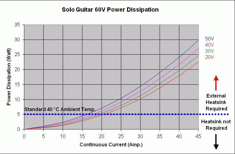
47 Powering Up After the Solo Guitar is connected to its device, it is ready to be powered up. Caution: Before applying power, ensure that the DC supply is within the specified range and that the proper plus-minus connections are in order Initializing the System After the Solo Guitar has been connected and mounted, the system must be set up and initialized. This is accomplished using the Composer, Elmo s Windows-based software application. Install the application and then perform setup and initialization according to the directions in the Composer Software Manual Heat Dissipation The best way to dissipate heat from the Solo Guitar is to mount it so that its heatsink faces up. For best results leave approximately 10 mm of space between the Solo Guitar s heatsink and any other assembly. The Heat Dissipation data is shown graphically below:
48 3-35
49 How to Use the Charts The charts above are based upon theoretical worst-case conditions. Actual test results show 30% - 50% better power dissipation. To determine if your application needs a heatsink: 1. Allow maximum heatsink temperature to be 80 C or less. 2. Determine the ambient operating temperature of the Solo Guitar. 3. Calculate the allowable temperature increase as follows: for an ambient temperature of 40 C, ΔT= 80 C 40 C = 40 C 4. Use the chart to find the actual dissipation power of the drive. Follow the voltage curve to the desired output current and then find the dissipated power. 5. If the dissipated power is below 5 W the Solo Guitar will need no additional cooling. Note: The chart above shows that no heatsink is needed when the heatsink temperature is 80 C, ambient temperature is 40 C and heat dissipated is 5 Watts.
50 A-1 Appendix: Technical Specifications A.1 Features A.1.1 Motion Control Modes Current/Torque - Velocity - Position - up to 14 khz sampling rate up to 7 khz sampling rate up to 3.5 khz sampling rate A.1.2 Advanced Positioning Control Modes PTP, PT, PVT, ECAM, Follower, Dual Loop, Current Follower Fast event capturing inputs Fast output compare (OC) Motion Commands: Analog current and velocity, PWM current and velocity, digital (SW) and Pulse and Direction A.1.3 Advanced Filters and Gain Scheduling On-the-Fly gain scheduling of current and velocity Velocity and position with PIP controllers Automatic commutation alignment Automatic motor phase sequencing A.1.4 Fully Programmable Third generation programming structure with motion commands Metronome Event capturing interrupts Event triggered programming A.1.5 Feedback Options Incremental Encoder up to 20 Mega-Counts (5 Mega-Pulse) per second Digital Halls up to 2 khz Incremental Encoder with Digital Halls for commutation up to 20 Mega- Counts per second for encoder Interpolated Analog Sine/Cosine Encoder up to 250 khz (analog signal) Internal Interpolation - up to x4096 Automatic Correction of amplitude mismatch, phase mismatch, signal offset Emulated encoder outputs, single-ended, unbuffered of the Analog encoder Analog Hall Sensor Resolver Programmable 10~15 bit resolution Up to 512 revolutions per second (RPS) Emulated encoder outputs, single-ended, unbuffered of the Resolver. Auxiliary Encoder inputs (ECAM, follower, etc.) single-ended, unbuffered. Tachometer & Potentiometer The Solo Guitar can provide power (5 V, 2x200 ma max) for Encoders, Resolver or Halls.
51 Technical Specifications A-2 A.1.6 Input/Output One Analog Input up to 14-bit resolution Five separate programmable Digital Inputs, optically isolated (two of which are fast event capture inputs). Inhibit/Enable motion Software and analog reference stop Motion limit switches Begin on input Abort motion Homing General-purpose Four separate programmable Digital Outputs, optically isolated (open collector) one with fast output compare (OC): Brake Control Amplifier fault indication General-purpose Servo enable indication Pulse and Direction inputs (Differential) PWM current command output for torque and velocity A.1.7 Built-In Protection Software error handling Abort (hard stops and soft stops) Status reporting Protection against: Shorts between motor power outputs Shorts between motor power outputs and power input/return Failure of internal power supplies Over-heating Continuous temperature measurement. Temperature can be read on the fly; a warning can be initiated x degrees before temperature disable is activated. Over/Under voltage Loss of feedback Following error Current limits
52 Technical Specifications A-3 A.1.8 Accessories Heat sinks (TBD) A.1.9 Status Indication Output for a bi-color LED A.1.10 Automatic Procedures Commutation alignment Phase sequencing Current loop offset adjustment Current loop gain tuning Current gain scheduling Velocity loop offset adjustment Velocity gain tuning Velocity gain scheduling Position gain tuning
53 Technical Specifications A-4 A.2 Solo Guitar Dimensions
54 Technical Specifications A-5 A.3 Power Ratings Feature Minimum supply voltage Nominal supply voltage Maximum supply voltage Maximum continuous power output Efficiency at rated power (at nominal conditions) Maximum output voltage Amplitude sinusoidal/dc continuous current Sinusoidal continuous RMS current limit (Ic) Units 35/48 20/60 25/60 35/60 20/100 25/100 3/200 VDC VDC VDC W % > 97 6/200 10/200 17/200 97% of DC bus voltage at f=22 khz A A Peak current limit A 2 x Ic No peak Weight g (oz) 200 g (7.05 oz) Dimensions Digital in/digital out/analog in mm (in) 80 x 61 x 46.7 (3.15" x 2.4" x 1.84") 5/4/1 R45/48 R45/60 R35/100 R30/200 Note: Current rating: The current ratings of the Solo Guitar are given in units of DC amperes (ratings that are used for trapezoidal commutation or DC motors). The RMS (sinusoidal commutation) value is the DC value divided by 1.41.
55 Technical Specifications A-6 A.4 Environmental Conditions Feature Details Operating ambient temperature 0 ~ 40 C (32 ~ 104 F) Storage temperature -20 ~ +85 C ( -4 ~ +185 F) Humidity Maximum Operating Altitude Protection level 90% maximum non-condensing Unlimited (above 10,000 m - 30,000 feet) N/A A.4.1 Auxiliary Supply Feature Auxiliary power supply Auxiliary supply input voltage Auxiliary supply input power Details Isolated DC source only 12 VDC ~ 195 VDC < 7.5 VA (this includes the 5 V/2x200 ma load for the main and auxiliary encoders) A.5 Control Specifications A.5.1 Current Loop Feature Controller type Compensation for bus voltage variations Details Vector, digital On-the-fly automatic gain scheduling Motor types AC brushless (sinusoidal) DC brushless (trapezoidal) DC brush Linear motors Voice coils Current control Fully digital Sinusoidal with vector control Programmable PI control filter based on a pair of PI controls of AC current signals and constant power at high speed Current loop bandwidth Current sampling time Current sampling rate < 2.5 khz Programmable μsec Up to 16 khz; default 11 khz
56 Technical Specifications A-7 A.5.2 Velocity Loop Feature Controller type Details PI Velocity control Fully digital Velocity and position feedback options Velocity loop bandwidth Velocity sampling time Velocity sampling rate Programmable PI and FFW control filters "On-the-fly" gain scheduling Automatic, manual and advanced manual tuning Incremental Encoder Digital Halls Interpolated Analog (sin/cos) Encoder (optional) Resolver (optional) Tachometer and Potentiometer (optional) Note: With all feedback options, 1/T with automatic mode switching is activated (gap, frequency and derivative). < 350 Hz μsec (2x current loop sample time) Up to 8 khz; default 5.5 khz Velocity command options Analog Internally calculated by either jogging or step Note: All software-calculated profiles support on-the-fly changes. A.5.3 Position Loop Feature Controller type Details PIP Position command options Software Position loop bandwidth Position sampling time Position sampling rate Pulse and Direction Analog Potentiometer < 80 Hz μsec (4x current loop sample time) Up to 4 khz; default 2.75 khz
57 Technical Specifications A-8 A.6 Feedbacks A.6.1 Feedback Supply Voltage The Solo Guitar has two feedback ports (Main and Auxiliary). The Solo Guitar supplies voltage only to the main feedback device and to the auxiliary feedback device if needed. Feature Main encoder supply voltage Auxiliary encoder supply voltage Details 5 V 200 ma maximum 5 V 200 ma maximum A.6.2 Main Feedback Options A Incremental Encoder Input Feature Encoder format Interface Input resistance Maximum incremental encoder frequency Minimum quadrature input period (PIN) Minimum quadrature input high/low period (PHL) Minimum quadrature phase period (PPH) Maximum encoder input voltage range Details A, B and Index Differential Quadrature RS-422 Differential: 120 Ω (TBD) Maximum absolute: 5 MHz pulses 112 nsec 56 nsec 28 nsec Common mode: ±7 V Differential mode: ±7 V Figure A-1: Main Feedback - Encoder Phase Diagram
58 Technical Specifications A-9 A Digital Halls Feature Details Halls inputs H A, H B, H C. Input voltage Input current Maximum frequency Single ended inputs Built in hysteresis of 1V for noise immunity Nominal operating range: 0 V < V In_Hall < 5 V Maximum absolute: -1 V < V In_Hall < 15 V High level input voltage: V InHigh > 2.5 V Low level input voltage: V InLow < 1 V Sink current (when input pulled to the common): 5 ma f MAX : 2 khz A Interpolated Analog Encoder (Sine/Cosine) Feature Details Analog encoder format Sine and Cosine signals Analog input signal level Offset voltage: 2.2 V 2.8 V Differential, 1 V peak to peak Input resistance Differential 120 Ω Maximum analog signal frequency Interpolation multipliers Maximum counts frequency Automatic errors correction Encoder outputs A Resolver Feature f MAX : 250 khz Programmable: x4 to x mega-counts/sec internally Signal amplitudes mismatch Signal phase shift Signal offsets See Auxiliary Encoder Outputs specifications ( A.6.3) Details Resolver format Sine/Cosine Differential Input resistance Resolution Maximum electrical frequency (RPS) Differential 2.49 kω Programmable: 10 ~ 15 bits 512 revolutions/sec Resolver transfer ratio 0.5 Reference frequency 1/Ts (Ts = sample time in seconds)
59 Technical Specifications A-10 Feature Reference voltage Reference current Encoder outputs A Tachometer* Feature Tachometer format Maximum operating differential voltage for TAC1+, TAC1- Maximum absolute differential input voltage for TAC1+, TAC1- Maximum operating differential voltage for TAC2+, TAC2- Maximum absolute differential input voltage for TAC2+, TAC2- Input resistance for TAC1+, TAC1- Input resistance for TAC2+, TAC2- Resolution Details Supplied by the Solo Guitar up to ±50 ma See Auxiliary Encoder Output specifications ( A.6.3) Details Differential ±20 V ±25 V ±50 V ±60 V 46 kω 100 kω 14 bit * Only one Tachometer port can be used at a time (either TAC1+/TAC1- or TAC2+/TAC2-). TAC1+/TAC1- is used in applications with having a Tachometer of less than 20 V. TAC2+/TAC2- is used in applications with having a Tachometer of between 20 V and 50 V. A Potentiometer Feature Potentiometer Format Operating Voltage Range Potentiometer Resistance Input Resistance Resolution Details Single-ended 0 ~ 5 V supplied by the Solo Guitar 100 Ω ~ 1 kω above this range, linearity is affected detrimentally 100 kω 14 bit
60 Technical Specifications A-11 A.6.3 Main Encoder Buffered Output Feature Main encoder buffered output Interface Output current capability Available as options Maximum frequency Index (marker) Details A, B, Index Differential outputs Quadrature RS-422 Driving differential loads of 200 Ω on INDEX/ INDEX-, CHB/CHB- and CHA/CHA- pairs Simultaneous buffered outputs of mainincremental encoder input f MAX : 5 MHz pulses/output Length of pulse is one quadrature (one quarter of an encoder cycle) and synchronized to A&B A.6.4 Auxiliary Feedback Port (output mode YA[4]= 4) Feature Details Emulated output A, B, Index Differential Output current capability Maximum output current: I OH (max) = 2 ma High level output voltage: V OH > 3.0 V Minimum output current: I OL = 2 ma Low level output voltage: V OL < 0.4 V Available as options Emulated encoder outputs of analog encoder Emulated encoder outputs of the resolver Emulated encoder outputs of the tachometer Emulated encoder outputs of the potentiometer Maximum frequency Edge separation between A & B Index (marker): f MAX : 5 MHz pulses/output Programmable number of clocks to allow adequate noise filtering at remote receiver of emulated encoder signals Length of pulse is one quadrature (one quarter of an encoder cycle) and synchronized to A&B
Whistle/Tweeter Digital Servo Drives Installation Guide
 Whistle/Tweeter Digital Servo Drives Guide July 2010 (Ver. 1.5) www.elmomc.com Notice This guide is delivered subject to the following conditions and restrictions: This guide contains proprietary information
Harmonica Digital Servo Drive Technical Specifications
 Harmonica Digital Servo Drive Technical Specifications March 2004 Notice This guide is delivered subject to the following conditions and restrictions: This guide contains proprietary information belonging
Guitar Digital Servo Drive Installation Guide
 Guitar Digital Servo Drive Guide March 2013 (Ver. 1.503) Notice This guide is delivered subject to the following conditions and restrictions: This guide contains proprietary information belonging to Elmo
Gold Our Best Ever Motion Solutions
 Elmo's Line Our Best Ever Motion Solutions The Trombone An Ultra-Compact 400 VDC & 800 VDC "Direct to Mains" Networking Servo Drive Up to 7 kw of Qualitative Power Motion Control Solutions Made Small,
The Gold Duo Highly Compact Dual Axis Networking Servo Drive Up to 1.6 kw (3.2 kw Peak) of Qualitative Power Per Drive
 of Qualitative Power Per Drive") Elmo's Line Our Best Ever Motion Solutions The Duo Highly Compact Dual Axis Networking Servo Drive Up to 1.6 kw (3.2 kw Peak) of Qualitative Power Per Drive Motion Control Solutions Made Small, Smart &
Elmo's Line Our Best Ever Motion Solutions The Duo Highly Compact Dual Axis Networking Servo Drive Up to 1.6 kw (3.2 kw Peak) of Qualitative Power Per Drive Motion Control Solutions Made Small, Smart &
Whistle and Tweeter Digital Servo Drives Installation Guide
 Whistle and Tweeter Digital Servo Drives Guide February 2013 (Ver. 1.602) Notice This guide is delivered subject to the following conditions and restrictions: This guide contains proprietary information
Eagle Digital Servo Drive Installation Guide
 Eagle Digital Servo Drive Guide November 2011 (Ver. 1.7) Notice This guide is delivered subject to the following conditions and restrictions: This guide contains proprietary information belonging to Elmo
Digital Servo Drives
 Digital Servo Drives & Motion Controllers Technical Data www.motiontech.com.au 1 of 24 2 of 24 Table of Contents A) For general purpose, industrial applications: Features 4 Tweeter, 7.5~95VDC, 2.5~3.3A
Application Note Homing in SimplIQ Servo Drives
 Application Note Homing in SimplIQ Servo Drives Rev. 8 June 2010 2 Introduction Most servo applications use a relative (incremental) encoder as feedback for the controller and servo drive. Incremental
Gold Cello Digital Servo Drive Installation Guide EtherCAT and CAN
 Gold Cello Digital Servo Drive Guide EtherCAT and CAN February 2013 (Ver. 1.101) www.elmomc.com Notice This guide is delivered subject to the following conditions and restrictions: This guide contains
Gold Duo Digital Servo Drive Installation Guide EtherCAT
 Gold Duo Digital Servo Drive Guide EtherCAT May 2012 (Ver. 1.4) Notice This guide is delivered subject to the following conditions and restrictions: This guide contains proprietary information belonging
maxon document number:
 maxon document number: 791272-04 1 Table of contents... 2 2 Table of figures... 3 3 Introduction... 4 4 How to use this guide... 4 5 Safety Instructions... 5 6 Performance Data... 6 6.1 Motor data... 6
Peak Current. Continuous Current. See Part Numbering Information on last page of datasheet for additional ordering options.
 Description Power Range The PWM servo drive is designed to drive brushless DC motors at a high switching frequency. A single red/green LED indicates operating status. The drive is fully protected against
Intelligence. is Simplicity
 Intelligence is Simplicity Elmo Motion Control Setting the wheels of industry in motion Meticulous management of power. Precision of movement. Flawless performance. These are the essential attributes that
Gold Solo Whistle Digital Servo Drive Installation Guide
 Gold Solo Whistle Digital Servo Drive Guide EtherCAT and CAN March 2013 (Ver. 1.403) www.elmomc.com Notice This guide is delivered subject to the following conditions and restrictions: This guide contains
Analog Servo Drive 30A8
 Description Power Range The 30A8 PWM servo drive is designed to drive brush type DC motors at a high switching frequency. A single red/green LED indicates operating status. The drive is fully protected
IC800SSD Hardware Manual Pub 348R5. for models. A publication of
 IC800SSD Hardware Manual Pub 348R5 for models IC800SSD104S1A IC800SSD104RS1A IC800SSD107S1A IC800SSD107RS1A IC800SSD407RS1A IC800SSD216S1A IC800SSD216RS1A IC800SSD420RS1A IC800SSD228S1A IC800SSD228RS1A
Analog Servo Drive. Peak Current 16 A (11.3 A RMS )
") Description The PWM servo drive is designed to drive three phase brushless motors with sine wave current at a high switching frequency. The drive requires two sinusoidal command signals with a 120-degree
Description The PWM servo drive is designed to drive three phase brushless motors with sine wave current at a high switching frequency. The drive requires two sinusoidal command signals with a 120-degree
Analog Servo Drive. Continuous Current. Features
 Description Power Range The PWM servo drive is designed to drive three phase brushless motors with sine wave current at a high switching frequency. The drive requires two sinusoidal command signals with
Analog Servo Drive 20A20
 Description Power Range NOTE: This product has been replaced by the AxCent family of servo drives. Please visit our website at www.a-m-c.com or contact us for replacement model information and retrofit
815-BR SERVO AMPLIFIER FOR BRUSH SERVOMOTORS
 815-BR SERVO AMPLIFIER FOR BRUSH SERVOMOTORS USER GUIDE September 2004 Important Notice This document is subject to the following conditions and restrictions: This document contains proprietary information
AxCent Servo Drive A25A100
 Description Power Range The A25A100 PWM servo drive is designed to drive brush type DC motors at a high switching frequency. A single red/green LED indicates operating status. The drive is fully protected
Analog Servo Drive 100A40
 Description Power Range The 100A40 PWM servo drive is designed to drive brush type DC motors at a high switching frequency. A single red/green LED indicates operating status. The drive is fully protected
All drive and motor parameters are stored in nonvolatile. Features
 Description Power Range The DigiFlex Performance (DP) Series digital servo drives are designed to drive brushed and brushless servomotors. These fully digital drives operate in torque, velocity, or position
Analog Servo Drive 30A8
 Description Power Range NOTE: This product has been replaced by the AxCent family of servo drives. Please visit our website at www.a-m-c.com or contact us for replacement model information and retrofit
AxCent Servo Drive A50A100
 Description Power Range The A50A100 PWM servo drive is designed to drive brushed type DC motors at a high switching frequency. A single red/green LED indicates operating status. The drive is fully protected
Analog Servo Drive 30A20AC
 Description Power Range NOTE: This product has been replaced by the AxCent family of servo drives. Please visit our website at www.a-m-c.com or contact us for replacement model information and retrofit
Flute Analog Servo Drive Installation Guide
 Flute Analog Servo Drive Installation Guide July 2014 (Ver. 2.301) Notice This guide is delivered subject to the following conditions and restrictions: This guide contains proprietary information belonging
Motion Control. Ready for the Extreme
 Motion Control Ready for the Extreme Elmo Motion Control - Inspiring Motion Since 1988 Elmo designs and manufactures cutting-edge servo drives and network motion controllers that are one-stop solutions
Analog Servo Drive 25A20DD
 Description Power Range NOTE: This product has been replaced by the AxCent family of servo drives. Please visit our website at www.a-m-c.com or contact us for replacement model information and retrofit
BLuAC5 Brushless Universal Servo Amplifier
 BLuAC5 Brushless Universal Servo Amplifier Description The BLu Series servo drives provide compact, reliable solutions for a wide range of motion applications in a variety of industries. BLu Series drives
Galil Motion Control. DMC 3x01x. Datasheet
 Galil Motion Control DMC 3x01x Datasheet 1-916-626-0101 Galil Motion Control 270 Technology Way, Rocklin, CA [Type here] [Type here] (US ONLY) 1-800-377-6329 [Type here] Product Description The DMC-3x01x
Logosol AC/DC Intelligent Servo Drive for Coordinated Control LS-174WP
 Features Motors supported: - Panasonic A and S series - Brushless 60/120 commutated - Brush-commutated (DC) motors Up to 20A peak, 12A continuous output current 12 to 90VDC power supply Separate motor
SERVOSTAR S- and CD-series Sine Encoder Feedback
 SERVOSTAR S- and CD-series Sine Encoder Feedback The SERVOSTAR S and SERVOSTAR CD family of drives offers the ability to accept signals from various feedback devices. Sine Encoders provide analog-encoded
BLuAC5 Brushless Universal Servo Amplifier
 BLuAC5 Brushless Universal Servo Amplifier Description The BLu Series servo drives provide compact, reliable solutions for a wide range of motion applications in a variety of industries. BLu Series drives
Analog Servo Drive B25A20
 Description Power Range NTE: This product has been replaced by the AxCent family of servo drives. Please visit our website at www.a-m-c.com or contact us for replacement model information and retrofit
DigiFlex Performance Servo Drive DZCANTE-020L080
 Description Power Range The DZCANTE-020L080 digital servo drive is designed to drive brushed and brushless servomotors, stepper motors, and AC induction motors from a compact form factor ideal for embedded
MTS Automation P R O D U C T S P E C I F I C A T I O N. MaxPlus Digital Servo Drive. MP-FLX 230 Series. MP-FLX 230 Series. Single- and Dual-Axis
 P R O D U C T S P E C I F I C A T I O N MaxPlus Digital Servo Drive MP-FL 230 Series MP-FL 230 Series Single- and Dual-Axis At two times the standard industry speed for digital current loop update rates,
IMC-316P Hardware Manual for model IMC-316P-X-D
 IMC-316P Hardware Manual for model IMC-316P-X-D Pub 352r0 A publication of 1050 Highland Drive Ann Arbor, Michigan 48108 Phone: (734) 665-5473 Fax: (734) 665-6694 www.whedco.com 2000 Whedco Incorporated,
DigiFlex Servo Drive DPQNNIE-060A400
 Description The DigiFlex Performance (DP) Series digital servo drives are designed to drive brushed and brushless servomotors. These fully digital drives operate in torque, velocity, or position mode and
DigiFlex Performance Servo Drive DPCANIA-060A400
 DigiFlex Performance Servo Drive DPCANA-060A400 Description Power Range The DigiFlex Performance (DP) Series digital servo drives are designed to drive brushed and brushless servomotors. These fully digital
LCC-10 Product manual
 LCC-10 Product manual Rev 1.0 Jan 2011 LCC-10 Product manual Copyright and trademarks Copyright 2010 INGENIA-CAT, S.L. / SMAC Corporation Scope This document applies to i116 motion controller in its hardware
DigiFlex Performance Servo Drive DPRAHIR-060A400
 DigiFlex Performance Servo Drive DPRAHR-060A400 Description Power Range The DigiFlex Performance (DP) Series digital servo drives are designed to drive brushed and brushless servomotors. These fully digital
IRT Mini Evo. Technical Manual. quality IN MOTION. quality IN MOTION
 IRT quality IN MOTION www.irtsa.com 2000 Mini Evo Technical Manual IRT quality IN MOTION Contents 1. INTRODUCTION 3 2. DESCRIPTION 5 3. TECHNICAL DATA 7 3.1 GENERAL DATA FOR ALL TYPES 7 3.2 SPECIFIC DATA
IRT AT-Small. Technical Manual. quality IN MOTION. quality IN MOTION
 IRT quality IN MOTION www.irtsa.com 2000 AT-Small Technical Manual IRT quality IN MOTION E2 0 8 4 1 5 September 2013-Rev. 4 UL Requirements Drives Series 2000 / 4000 AT 1. Field wiring terminal to use
Inverter Drive /Vector Drive Motors & Controls
 H2 Inverter/ Encoderless Vector Inverter Drive /Vector Drive & Controls 3/4 thru 50 180-264 VAC 3 Phase - 50/60 Hz 3/4 thru 60 340-528 VAC 3 Phase - 50/60 Hz 3/4 thru 60 515-660 VAC 3 Phase - 60 Hz HVAC
AxCent Servo Drive AZBE10A4IC
 Description Power Range The AZBE10A4C interface card and PWM servo drive assembly is designed to drive brushless and brushed DC motors at a high switching frequency. The interface card features quick-disconnect
DigiFlex Performance DPC Drives. CANopen Communication. Hardware Installation Manual ORIGINAL INSTRUCTIONS. Everything s possible.
 Everything s possible. DigiFlex Performance DPC Drives CANopen Communication Hardware Installation Manual www.a-m-c.com MNDGDCIN-09 ORIGINAL INSTRUCTIONS Preface ADVANCED Motion Controls constantly strives
Compact, Low-Cost Solutions
 Catalog 8-4/USA 77 & 77X Compact, Low-Cost Solutions The Making of a Servo System Servo systems rely on feedback devices to continuously correct for errors in current or torque, velocity, and position.
Dynamo Brushless DC Motor and GreenDriveTM Manual
 Dynamo Brushless DC Motor and GreenDriveTM Manual This manual was developed as a guide for use by FIRST Robotics Teams using Controller Part Number 840205-000 in conjunction with the Nidec Dynamo BLDC
DigiFlex Performance Servo Drive DPQNNIE-030A800
 DigiFlex Performance Servo Drive DPQNNE-030A800 Description Power Range The DigiFlex Performance (DP) Series digital servo drives are designed to drive brushed and brushless servomotors. These fully digital
XC4e PWM Digital Drive
 PWM Digital Drive HyperWire fiber-optic interface Up to 30 A peak output current Integral power supply Amplifiers/Drives Drive brush, brushless, voice coil, or stepper motors Safe torque off (STO) safety
Xenus XSL User Guide P/N
 Xenus XSL User Guide P/N 95-00286-000 Revision 7 June 2008 Xenus XSL User Guide This page for notes. TABLE OF CONTENTS About This Manual... 8 Overview and Scope... 8 Related Documentation... 8 Comments...
VF-nC1 Adjustable Speed Drive Engineering Specification
 PART 1 - GENERAL 1.0 Scope This specification shall cover Toshiba VF-nC1 AC Variable Frequency Drives, 6 pulse for 100V single-phase 0.1 to 0.75kW, 200V single-phase 0.2 to 2.2kW and 200V threephase 0.1
DigiFlex Performance DPC Drives. CANopen Communication. Hardware Installation Manual ORIGINAL INSTRUCTIONS. Everything s possible.
 Everything s possible. DigiFlex Performance DPC Drives CANopen Communication Hardware Installation Manual www.a-m-c.com MNDGDCIN-10 ORIGINAL INSTRUCTIONS Preface ADVANCED Motion Controls constantly strives
SVAC3. 400W AC Powered Servo Drive. Accessories C IP IP IP C IP. Control Options* For more information, visit:
 Feedback E = Encoder board 3 = 3.5A cont, 7.4A peak, 120VA 1.8A cont, 5.4A peak, 220VA ontrol S = Basic version Q = Q Programming = EtherNet/ BLuA5-Si SVA3-S-E120 SVA3-S-E220 SVA3-Q-E120 SVA3-Q-E220 SVA3--E120
SV2Dx Servo Drives SV200 Servo Drives for DC-Powered Applications
 24 to 60 VDC input 10 A cont., 20 A peak output current Compact size for multi-axis applications Ideal for OEMs Designed for use with J Series motors Wide range of control options 8 regular digital inputs,
Soloist. Position Controller and Servo Amplifier PWM. Single axis digital servo controller with integral power supply and amplifier
 Soloist Position Controller and Servo Amplifier PWM Single axis digital servo controller with integral power supply and amplifier Advanced software architecture shortens customer development time; use
1525-BRS INFORMATION MANUAL SERV O D YN A M ICS. D y n ad r iv e Ave Crocker Suite 10 Valencia, CA
 28231 Ave Crocker Suite 10 Valencia, CA 91355 818-700-8600 Servodynamics.com INFORMATION MANUAL 1525-BRS SERV O D YN A M ICS U SA www.servodynamics.com D y n ad r iv e Bru sh INDEX Page INTRODUCTION 2
B25A20FAC SERIES BRUSHLESS SERVO AMPLIFIERS Model: B25A20FAC 120VAC Single Supply Operation
 B25A20FAC Series B25A20FAC SERIES BRUSHLESS SERVO AMPLIFIERS Model: B25A20FAC 120VAC Single Supply Operation FEATURES: All connections on front of amplifier Surface-mount technology Small size, low cost,
MTY (81)
") This manual describes the option "d" of the SMT-BD1 amplifier: Master/slave electronic gearing. The general information about the digital amplifier commissioning are described in the standard SMT-BD1 manual.
This manual describes the option "d" of the SMT-BD1 amplifier: Master/slave electronic gearing. The general information about the digital amplifier commissioning are described in the standard SMT-BD1 manual.
AxCent Servo Drive AB25A100
 Description Power Range The AB25A100 PWM servo drive is designed to drive brushless and brushed DC motors at a high switching frequency. A single red/green LED indicates operating status. The drive is
DigiFlex Servo Drive DPQNNIE-015B200
 Description The DigiFlex Performance (DP) Series digital servo drives are designed to drive brushed and brushless servomotors. These fully digital drives operate in torque, velocity, or position mode and
IF30. User's manual. Description. Table of contents IF30
 User's manual IF30 Description IF30 is an encoder interface unit designed to convert the output signals delivered by so-called sine-cosine-encoders and similar measuring systems (devices which deliver
Application Note: Pulse and Direction for the Position and Velocity Commands
 d i g i t a l Motion Controller Pulse & Direction Incremental Encoder & Hall Application Note: Pulse and Direction for the Position and Velocity Commands Rev. 1.0 April 2009 2 Introduction Pulse and direction
Xenus XTL User Guide P/N
 Xenus XTL User Guide P/N 95-00875-000 Revision 3 June 2008 This page for notes. TABLE OF CONTENTS About This Manual... 5 1: Introduction... 9 1.1: Amplifier... 10 1.2: CME 2... 11 1.3: CMO/CML... 11 2:
Analog Servo Drive BD15A8
 Description Power Range The BD15A8 PWM servo drive is designed to drive brushless DC motors at a high switching frequency. t is fully protected against over-voltage, over-current, over-heating and short-circuits.
XC4e PWM Digital Drive
 XC4e PWM Digital Drive HyperWire fiber-optic interface Up to 30 A peak output current Integral power supply Drive brush, brushless, voice coil, or stepper motors Safe torque off (STO) safety circuit Drive
MMP SA-715A SERVO AMPLIFIER
 SERVO AMPLIFIER Description The MMP SA-715A servo amplifier is designed to drive brushed or brushless type DC motors at a high switching frequency. A single red/green LED indicates operating status. The
Analog Servo Drive. Features
 Description Power Range The PWM servo drive is designed to drive brushless DC motors at a high switching frequency. A single red/green LED indicates operating status. The drive is fully protected against
Design Characteristics. FlexDrive II. Series
 AC AC DC DC FlexDrive II Series Design Characteristics Brushless AC Servo Baldor s FlexDrive II series are designed to provide reliable and durable operation. Options are available to operate either resolver
S100A40AC SERIES BRUSHLESS SERVO AMPLIFIERS Model: S100A40AC
 S100A-AC Series S100A40AC SERIES BRUSHLESS SERVO AMPLIFIERS Model: S100A40AC FEATURES: Surface-mount technology Small size, low cost, ease of use Optical isolation, see block diagram Sinusoidal drive and
The MaxPlus SFD 230 Connectivity and ease of use in a compact, cost-effective digital solution.
 SFD Digital Drive Overview The MaxPlus SFD 0 Connectivity and ease of use in a compact, cost-effective digital solution. Meeting your expectations. t the MTS Systems Corporation, utomation Division, we
High Frequency Sinewave Guardian TM Filter
 High Frequency Sinewave Guardian TM Filter 380V 480V TECHNICAL REFERENCE MANUAL FORM: SHF-TRM-E REL. April 2015 REV. 001 2015 MTE Corporation Caution Prior to start up; confirm the drive operation mode
Servo Amplifier PMA 90 / 180
 Features Motors supported: - Brushless DC 60 /120 commutated - Brushed DC - Printed Armature DC 18 to 180VDC single power supply Up to 20A peak / 12A continuous current Selectable modes of operation: -
Npaq Series Drive Racks
 Npaq Series Drive Racks 3U plug-in drives 19 inch rack-mount design Flexible design provides the ability to drive brush, brushless, or stepper motors with the same amplifier 5 A to 30 A peak output current
Logosol Intelligent Hall-Servo Drive LS-173U Doc # / Rev. C, 02/12/2008
 Features Specially designed for control of brushless motors without encoder Hall-Servo and Encoder-Servo control modes Motors supported: - Brushless 60/120 commutated (AC) - Brush-commutated (DC) Up to
XC4 PWM Digital Drive
 XC4 PWM Digital Drive HyperWire fiber-optic interface Up to 30 A peak output current Integral power supply Drive brush, brushless, voice coil, or stepper motors Safe torque off (STO) safety circuit Drive
TETRIS 1000 High Impedance Active Probe. Instruction Manual
 TETRIS 1000 High Impedance Active Probe Instruction Manual Copyright 2015 PMK GmbH All rights reserved. Information in this publication supersedes that in all previously published material. Specifications
PRELIMINARY AVB250A060 PRELIMINARY. Servo Drive. Peak Current (10 seconds)
") Description Power Range The servo amplifiers are designed to drive brushless DC motors at a high switching frequency for vehicle applications. t is fully protected against over-voltage, over-current, over-heating,
Description Power Range The servo amplifiers are designed to drive brushless DC motors at a high switching frequency for vehicle applications. t is fully protected against over-voltage, over-current, over-heating,
PIC SERIES. Installation and Operating Manual. Elmo Motion Control. Rev.: 05/99
 PIC SERIES Installation and Operating Manual Rev.: 05/99 PIC - SAFETY INSTRUCTIONS Read this page carefully before installation and use of the instrument, and follow all instructions in section 4 of Installation
Ametek, Inc. Rotron Technical Products Division. 100 East Erie St., Suite 200 Kent, Ohio User's Guide. Number Revision F
 Ametek, Inc. Rotron Technical Products Division 100 East Erie St., Suite 200 Kent, Ohio 44240 User's 120 Volt, 800 Watt and 240 Volt, 1200 Watt Brushless Motor Drive Electronics 5.7" (145 mm) and 7.2"
DynaDrive INFORMATION MANUAL SDFP(S)
") DynaDrive INFORMATION MANUAL SDFP(S)1525-17 SERVO DYNAMICS CORP. 28231 Avenue Crocker, Santa Clarita, CA. 91355 (818) 700-8600 Fax (818) 718-6719 www.servodynamics.com INDEX Page INTRODUCTION 2 ELECTRICAL
DynaDrive INFORMATION MANUAL SDFP(S)1525-17 SERVO DYNAMICS CORP. 28231 Avenue Crocker, Santa Clarita, CA. 91355 (818) 700-8600 Fax (818) 718-6719 www.servodynamics.com INDEX Page INTRODUCTION 2 ELECTRICAL
DDM3U-1-100V-15A-NP DDM3U-4-60V DDM3U-1-320V-15A-NP
 MC4U PWM Drives Drives 100V-15A-NP DDM3U-4-60V 320V-15A-NP Up to 4 Universal Drives per Card, 60V, 5A peak, 0.3kW One Axis universal Drive per Card, 100V and 320V, 30A peak, 8.2kW DDM3U-4-320V-1A DDM3U-4-320V-2A
7I25 H-BRIDGE MANUAL
 7I25 H-BRIDGE MANUAL VERSION 1.0 Copyright 2002 by MESA ELECTRONICS Richmond, CA. Printed in the United States of America. All rights reserved. This document and the data disclosed herein is not to be
EPOS2 24/2 EPOS2 24/5 DC (390438) EC (380264) DC/EC (390003) DCX (530239) (367676) (360665) (347717) (375711)
 EC (380264) DC/EC (390003) DCX (530239) (367676) (360665) (347717) (375711)") maxon motor control s EPOS2 are small-sized, full digital, smart positioning control units. Due to their flexible and high efficient power stage, the EPOS2 motion controllers drive brushed DC motors with
maxon motor control s EPOS2 are small-sized, full digital, smart positioning control units. Due to their flexible and high efficient power stage, the EPOS2 motion controllers drive brushed DC motors with
Ndrive Series. Digital Servo Amplifiers PWM. Wide output power range from 10 A peak to 200 A peak at 320 VDC. 2- or 3-phase AC line input or DC input
 Ndrive PWM Amplifiers/Drives Ndrive Series Digital Servo Amplifiers PWM Wide output power range from 10 A peak to 200 A peak at 320 VDC 2- or 3-phase AC line input or DC input CE approved and NRTL safety
High Frequency SineWave Guardian TM Filter
 High Frequency SineWave Guardian TM Filter 380V 480V TECHNICAL REFERENCE MANUAL WARNING High Voltage! Only a qualified electrician can carry out the electrical installation of this filter. Quick Reference
PAM & SAM System User s Manual
 PAM & SAM System User s Manual Part 5 - SAM Drive Technical Information Ordering Number: 9032 011 985 Issue November 14, 2000 This version replaces all previous versions of this document. It also replaces
Digital Servo Motor Driver
 SRVODRV-806 Description This digital servo drive is designed to drive brushed and brushless servomotors from a compact form factor ideal for embedded applications. This fully digital drive operates in
MLA High Performance Microstepping Driver. User s Guide E. Landon Drive Anaheim, CA
 MLA10641 High Performance Microstepping Driver User s Guide A N A H E I M A U T O M A T I O N 4985 E. Landon Drive Anaheim, CA 92807 e-mail: info@anaheimautomation.com (714) 992-6990 fax: (714) 992-0471
High-Performance Servo Drive Family. - E xperi ence - Va l u e. Valu
 High Servo Drive Family E xperi ence Va l u e Perform Experience Valu High Servo Drive Family Servotronix introduces CDHD, the nextgeneration high performance servo drive. CDHD features hardware and software
Installation Guide Multi Position Servo Controller E1100-MP and E1100-MP-HC
 Installation Guide Multi Position Servo Controller E00-MP and E00-MP-HC Content IMPORTANT NOTES FOR E00 SERIES CONTROLLERS 2 SYSTEM OVERVIEW 3 E00-MP SERIES FUNCTION AND WIRING 4 E00-MP-HC SERIES FUNCTION
S11 Adjustable Speed Drive Engineering Specification
 PART 1 - GENERAL 1.0 Scope This specification shall cover Toshiba S11 AC Variable Frequency Drives, 6 pulse for 3- phase 200-240VAC, 380-500VAC and single phase 200V to 240VAC. 1.1 References A. National
User's Manual: Series 350T AC Current Input (External Sensor), DC-Powered Transmitters
, DC-Powered Transmitters") User's Manual: Series 350T AC Current Input (External Sensor), DC-Powered Transmitters Table of Contents Page Introduction 1 Description 1 Specifications 2 Installation 3 Calibration 4 General Maintenance
User's Manual: Series 350T AC Current Input (External Sensor), DC-Powered Transmitters Table of Contents Page Introduction 1 Description 1 Specifications 2 Installation 3 Calibration 4 General Maintenance
8902/RE and 8902/RR Resolver Speed Feedback Options
 8902/RE and 8902/RR Resolver Speed Feedback Options Technical Manual HA469251U002 Issue 1 Compatible with Version 2.x and 3.x Software Copyright 2009 Parker SSD Drives, a division of Parker Hannifin Ltd.
TETRIS User's Guide. High Impedance Active Probe DO177-1
 TETRIS 1500 High Impedance Active Probe User's Guide DO177-1 TETRIS 1500 Copyright 2010 Ltd. All rights reserved. Information in this publication supersedes that in all previously published material. Specifications
8V General information. 2 Order data 8V
 8V05.00-8V05.00- General information Modular mechanical design using plug-in modules Integrated line filter Integrated braking resistor All connections are made using plug-in connectors Integrated electronic
M/V Series Servo Drive AB250A060
 Description Power Range AB250A060 servo amplifiers are designed to drive brushless DC motors at a high switching frequency. It is fully protected against over-voltage, over-current, over-heating, under-voltage
Brushless Servo Motor Drives xdrive Series
 Brushless Servo Motor Drives xdrive Series All-Digital, AC-Input, Velocity or Torque Control Allied Motion s xdrive servo drives are precision, all-digital DSP-based servo drive amplifiers capable of supplying