HPH Series J-Hook Installation Instructions
|
|
|
- Norman Perry
- 6 years ago
- Views:
Transcription


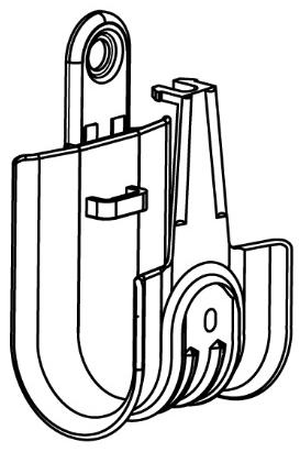
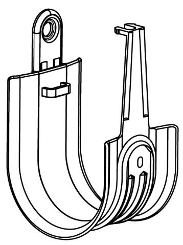
1 HPH Series J- Installation Instructions 1
 and an appropriate length for the substrate (1-B) to fasten the HPH J- (2) to the vertical surface (3). Insert the cables and close the latch as shown in 3.")
2 Mounting to a vertical surface: HPH16, HPH32, HPH48 and HPH64 Use a nail*, bolt* or screw* with a minimum head diameter of (1-A) and an appropriate length for the substrate (1-B) to fasten the HPH J- (2) to the vertical surface (3). Insert the cables and close the latch as shown in 3. The latch must be in the closed position as shown in 4 to secure the cables and complete the installation Part UL Load Rating HPH16 1" Standard HPH J-, size 16 HPH & Standard HPH J-, size 32 HPH Standard HPH J-, size 48 HPH Standard HPH J-, size 64 2
3 Mounting to a rod or ceiling wire with a Multi-Function Clip-Batwing: HPH16W, HPH32W, HPH48W and HPH64W HPHXXW J-s (1) are pre-assembled to Multi-Function Clip-Batwings at the factory using a fastener such as a rivet or a zinc plated ¼-20 x 3/8 pan head Phillips machine bolt and a grade A ¼-20 hex Nylon locknut (2). A plain HPH J- may be assembled to a UL listed batwing clip in the field with the use of a similar fastener. Depress the batwing between your fingers ( 3). Attach the HPHXXW to 12 gauge ceiling wire or 1/4" threaded rod (4 and 6). Insert the cables and close the latch (5 and 7). The latch must be in the closed position as shown in 8 to secure the cables and complete the installation
4 6 7 8 Part UL Load Rating HPH16W 1" Batwing HPH J-, size 16 HPH32W Batwing HPH J-, size 32 HPH48W 3 & Batwing HPH J-, size 48 8 HPH64W Batwing HPH J-, size 64 4
5 Mounting to a rod or a horizontal surface with an Angle Clip 90 : HPH16AC, HPH16AC6 HPH32AC, HPH32AC6, HPH48AC, HPH48AC6, HPH64AC & HPH64AC6 HPHXXAC and HPHXXAC6 J-s (1 and 2) are pre-assembled to Angle Clips 90 at the factory using a fastener such as a rivet or a zinc plated ¼-20 x 3/8 pan head Phillips machine bolt and a grade A ¼-20 hex Nylon locknut (3). A plain HPH J- may be assembled to a Platinum Tools Angle Clip 90 in the field using a similar fastener. Fasten the HPHXXAC or HPHXXAC6 to 1/4" or 3/8 threaded rod using two standard hex nuts (4). Thread a single nut up to the desired location of the threaded rod. Guide the HPHXXAC or HPHXXAC6 onto the threaded rod. Thread a second nut onto the threaded rod and tighten to the first nut, thereby sandwiching the Angle Clip 90 between the two nuts (5). An HPHXXAC or an HPHXXAC6 may be fastened directly to the underside of a horizontal surface using an appropriate fastener* (6). Use a fastener with an appropriate head diameter (7-A) and an appropriate length for the substrate (7-B). Place the cables in the hook and close the latch as shown in 5 and 6. The latch must be in the closed position as shown in 8 and 9 to secure the cables and complete the installation


6 Part UL Load Rating Angle Clip Hole HPH16AC 1" /4" 1 90 Angle HPH J-, size 16 HPH16AC / Angle/6 HPH J-, size 16 HPH32AC /4" 2 90 Angle HPH J-, size 32 HPH32AC / Angle/6 HPH J-, size 32 HPH48AC /4" 3 90 Angle HPH J-, size 48 HPH48AC / Angle/6 HPH J-, size 48 HPH64AC /4" 4 90 Angle HPH J-, size 64 HPH64AC / Angle/6 HPH J-, size 64 6
7 Mounting to a horizontal surface with an Angle Clip 90 w/powder Actuated Nail (PAN): HPH16ACPA, HPH32ACPA, HPH48ACPA and HPH64ACPA Use a powder actuated tool* to install the 1-5/16 pin into an appropriate material such as concrete as shown in 3 & Part Load Rating HPH16ACPA 1" Angle w/pan HPH J-, size 16 HPH32ACPA Angle w/pan HPH J-, size 32 HPH48ACPA 3 & Angle w/pan HPH J-, size 48 HPH64ACPA Angle w/pan HPH J-, size 64 7
8 Mounting to a beam with an HOK24 or HOK58 Hammer-On Beam Clamp: HPH16HOK24, HPH16HOK58, HPH32HOK24, HPH32HOK58, HPH48HOK24, HPH48HOK58, HPH64HOK24 and HPH64HOK58 Secure a Hammer-On Beam Clamp to a flange using a hammer as shown in 5 & 6 below. Note: The HOK-24 is designed for flanges from 1/8 to 1/4" thick; the HOK-58 is designed for flanges from 5/16 to 1/2" thick. Part UL Load Rating Designed for flanges HPH16HOK24 1" 1 & /8-1/4" 1 Hammer-On HPH J-, 1/8-1/4 flange, size 16 HPH16HOK & /16-1/2 1 Hammer-On HPH J-, 5/16-1/2 flange, size 16 HPH32HOK & /8-1/4" 2 Hammer-On HPH J-, 1/8-1/4 flange, size 32 HPH32HOK & /16-1/2 2 Hammer-On HPH J-, 5/16-1/2 flange, size 32 HPH48HOK & /8-1/4" 3 Hammer-On HPH J-, 1/8-1/4 flange, size 48 HPH48HOK & /16-1/2 3 Hammer-On HPH J-, 5/16-1/2 flange, size 48 HPH64HOK & /8-1/4" 4 Hammer-On HPH J-, 1/8-1/4 flange, size 64 HPH64HOK & /16-1/2 4 Hammer-On HPH J-, 5/16-1/2 flange, size
9 Mounting to a beam with an FM24 or FM58 Hammer-On Beam Clamp: HPH16ACFM24, HPH16ACFM58, HPH32ACFM24, HPH32ACFM58, HPH48ACFM24, HPH48ACFM58, HPH64ACFM24 and HPH64ACFM58 Secure a knock-on beam clamp to a flange using a hammer as shown in 5 & 6 below. Note: The ACFM24 is designed for flanges from 1/8" to 1/4" thick. The ACFM58 is designed for flanges from 5/16" to 1/2" thick. Both the ACFM24 & ACFM58 can be rotated Part UL Load Rating Designed for flanges HPH16ACFM24 1" 1 & /8-1/4" 1 Hammer-On HPH J-, Swivels 360, 1/8-1/4 Flange, size 16 HPH16ACFM & /16-1/2 1 Hammer-On HPH J-, Swivels 360, 5/16 1/2" Flange, size 16 HPH32ACFM & /8-1/4" 2 Hammer-On HPH J-, Swivels 360, 1/8-1/4 Flange, size 32 HPH32ACFM & /16-1/2 2 Hammer-On HPH J-, Swivels 360, 5/16 1/2" Flange, size 32 HPH48ACFM & /8-1/4" 3 Hammer-On HPH J-, Swivels 360, 1/8-1/4 Flange, size 48 HPH48ACFM & /16-1/2 3 Hammer-On HPH J-, Swivels 360, 5/16 1/2" Flange, size 48 HPH64ACFM & /8-1/4" 4 Hammer-On HPH J-, Swivels 360, 1/8-1/4 Flange, size 64 HPH64ACFM & /16-1/2 4 Hammer-On HPH J-, Swivels 360, 5/16 1/2" Flange, size
10 Mounting to a beam with a BC Beam Clamp: HPH16BC, HPH16ACBC, HPH32BC, HPH32ACBC, HPH48BC, HPH48ACBC, HPH64BC and HPH64ACBC Secure a screw-on beam clamp to a flange using a 3/8 socket driver or wrench as shown in 5, 6, 7, & 8 below. Tighten the bolt to 20 in-lb. Note: The BC & ACBC s are designed for flanges up to 1/2" thick. The ACBC can be rotated Part UL Load Rating Designed for flanges HPH16BC 1" 1 & Beam Clamp HPH J-, 16 HPH16ACBC 1 3 & Swivel 360 Beam Clamp HPH J-, size 16 HPH32BC 2 1 & Beam Clamp HPH J-, 32 HPH32ACBC 2 3 & /8-1/2" 2 Swivel 360 Beam Clamp HPH J-, size 32 HPH48BC 3 1 & Beam Clamp HPH J-, 48 HPH48ACBC 3 3 & Swivel 360 Beam Clamp HPH J-, size 48 HPH64BC 4 1 & Beam Clamp HPH J-, 64 HPH64ACBC 4 3 & Swivel 360 Beam Clamp HPH J-, size
11 7 8 Mounting to a beam with an SSBC Spring Steel Beam Clamp: HPH16SSBC, HPH16ACSSBC, HPH32SSBC, HPH32ACSSBC, HPH48SSBC, HPH48ACSSBC, HPH64SSBC and HPH64ACSSBC Secure a screw-on beam clamp to a flange using a 3/8 socket driver, wrench or Phillips head screw driver as shown in 5, 6, & 8 below. Tighten the bolt to 20 in-lb. Note: The SSBC & ACSSBC s are designed for flanges up to 1/2" thick. The ACSSBC can be rotated
12 Part Hoo k UL Load Rating Designed for flanges HPH16SSBC 1" 1 & Spring Steel Beam Clamp HPH J-, size 16 HPH16ACSSBC 1 3 & Swivel 360 Spring Steel Beam Clamp HPH J-, size 16 HPH32SSBC 2 1 & Spring Steel Beam Clamp HPH J-, size 32 HPH32ACSSBC 2 3 & /8-1/2" 2 Swivel 360 Spring Steel Beam Clamp HPH J-, size 32 HPH48SSBC 3 1 & Spring Steel Beam Clamp HPH J-, size 48 HPH48ACSSBC 3 3 & Swivel 360 Spring Steel Beam Clamp HPH J-, size 48 HPH64SSBC 4 1 & Spring Steel Beam Clamp HPH J-, size 64 HPH64ACSSBC 4 3 & Swivel 360 Spring Steel Beam Clamp HPH J-, size 64 12
13 Mounting to a joist with an Angled Overhang (AO) or Vertical Overhang (VO) spring steel clip: HPH16AO, HPH16VO, HPH32AO, HPH32VO, HPH48AO, HPH48VO, HPH64AO and HPH64VO Secure an AO spring steel Z purlin clip or a VO14 C purlin clip to a joist using a hammer as shown in 5, 6, 7, & 8 below. Note: The AO14 is designed for flanges 1/8-1/4" thick
14 7 8 Part UL Load Rating Designed for flanges HPH16AO 1" 1 & Angled Overhang HPH J-, size 16 HPH16VO 1 3 & Vertical Overhang HPH J-, size 16 HPH32AO 2 1 & Angled Overhang HPH J-, size 32 HPH32VO 2 3 & Vertical Overhang HPH J-, size 32 1/8-1/4" HPH48AO 3 1 & Angled Overhang HPH J-, size 48 HPH48VO 3 3 & Vertical Overhang HPH J-, size 48 HPH64AO 4 1 & Angled Overhang HPH J-, size 64 HPH64VO 4 3 & Vertical Overhang HPH J-, size 64 14
15 Mounting to threaded rod with a female threaded eye coupling: HPH16EH, HPH32EH, HPH48EH and HPH64EH Thread the eye coupling on to ¼-20 threaded rod as shown in 3, 4 & 5 below. 1 2 Part Load Rating HPH16EH 1" End ¼-20 HPH J-, size 16 HPH32EH End ¼-20 HPH J-, size 32 HPH48EH 3 & End ¼-20 HPH J-, size 48 HPH64EH End ¼-20 HPH J-, size 64 All HPH J-s on pages 6 through 15 are special order. Call us for details and lead times. * Consult the manufacturer s instructions and load ratings before using on your application. 15
Beam and Purlin Clamps Beam Clamps
 Metal Framing & Cable Tray Steel City Hangers, Clamps & Fasteners Beam and Purlin Clamps Beam Clamps Fits beam flanges to 2" Supports 4" and 8" threaded rod, S-hooks, electrical boxes, conduit and bridle
MPA-9000 Universal Ceiling Projector Mount Kit
 I N S T R U C T I O N M A N U A L Universal Ceiling Projector Mount Kit The Universal Ceiling Projector Mount provides a unique, simplified method of ceiling mounting your inverted projector. This low
SWAY BRACE PIPE ATTACHMENT FIG. 010
 Function: Designed for bracing pipe against sway and seismic disturbance. The pipe attachment component of a sway brace system used in conjunction with a PHD Manufacturing structural attachment fitting,
CSS Central Mount System
 CSS-20 Installation Manual CSS-20 Safety Notifications Below are the installation instructions for the CSS-20-2 Long Span Beam Mounting System. Please read these safety notifications prior to beginning
Tel: +44 (0)
") 4 Lindapter s support fixing range offers a series of ideal solutions for all building services. This includes the suspension of HVAC equipment, pipe work, fire protection/sprinkler systems, suspended
4 Lindapter s support fixing range offers a series of ideal solutions for all building services. This includes the suspension of HVAC equipment, pipe work, fire protection/sprinkler systems, suspended
mila-wall (Series100) General Operating Instructions page 1 of 15
 General Operating Instructions page 1 of 15") mila-wall (Series100) General Operating Instructions page 1 of 15 Step #1: Before setting up walls, lower adjustable leveling feet on each panel approximately 1". This will allow access to the threaded
mila-wall (Series100) General Operating Instructions page 1 of 15 Step #1: Before setting up walls, lower adjustable leveling feet on each panel approximately 1". This will allow access to the threaded
Hang-TITE Rod Hanger Screws
 Description The Hang-TITE Rod Hanger Screw is a one-piece, internally threaded anchor designed for suspending threaded rod for applications like cable-tray, pipe hanging, fire protection, and electrical
Kai Installation Instructions
 Kai Installation Instructions Before Beginning Installation Read through the entire instruction thoroughly A minimum of 2 people are required for this assembly These instructions reflect typical assemblies;
Installation Instructions
 Column & Beam Units with Debris Netting Installation Instructions Laminated Wood Systems, Inc. Seward, Nebraska 800-949-3526 2015 LWS, INC. AVR-NET INSTALL 05-12-16 AVR Installation Notes 1 Safety The
**MOUNTING YOUR MONITOR
 FPP72V200 72 FREE STANDING DISPLAY CART Assembly Instructions Hardware List Ref. Qty. Part No. Description AA 4 030-1128 1/4-20 UNC, 1 3/4 Socket Hd Screws BB 1 030-1129 5/8-11 UNC 1 3/4 Socket Hd Screw
Installation Guide. Mounting Kit for Mounting Philips Avalon CTS Cordless Fetal Transducer System on Wall, 2'' Post, Rail, or Slide-on Mounting Plate
 Installation Guide Mounting Kit for Mounting Philips Avalon CTS Cordless Fetal Transducer System on Wall, 2'' Post, Rail, or Slide-on Mounting Plate The purpose of this guide is to: 1. Describe mounting
Elco Construction Products 1301 Kerr Drive Decorah, IA fax:
 Technical Manual 2010 HangerMate anchors were designed to speed installation of fire sprinkler, HVAC, refrigeration, general piping, and electrical systems. They can also be used to install strut channels,
Copyright Black Box Corporation. All rights reserved Park Drive Lawrence, PA Fax
 Copyright 2003. Black Box Corporation. All rights reserved. 1000 Park Drive Lawrence, PA 15055-1018 724-746-5500 Fax 724-746-0746 JULY 2003 RM3010A RM315-R2 RM323-R2 RM329 RM451 RM457 RM3020A RM316 RM324-R2
ASSEMBLY AND ADJUSTMENT
 EDGE MONITOR ARM EDGE Rev A 2/17 Model EDGE-SLV Model EDGE-BLK Model EDGE-WHT ASSEMBLY AND ADJUSTMENT EDGE MONITOR ARM PARTS AND TOOLS PLEASE REVIEW these instructions before beginning the assembly and
Installation Instruction
 Tools Needed for Assembly Stud finder (for wood stud wall) Pencil Mark Electric drill Wood Stud Wall Installation Step 1. Locate the Wood Studs Installation Instruction Drill bit (for wood stud wall) Masonry
INSTALLATION INSTRUCTIONS DODGE RAM 2 & 4WD 1500 PART # P5058
 INSTALLATION INSTRUCTIONS 2009-13 DODGE RAM 2 & 4WD 1500 PART # P5058 PARTS LIST: Qty Description Qty Description 1 Grille Guard 12 12-1.75mm Hex Nuts 2 Upper Frame Mounting s (for trucks without tow hooks
GlideRite Retractable Cover System For Hot Spot Spas (SE & SLX only)
") List of Contents Quantity Description 12 #10 x 1 ½ Flat Head Phillips Screw (see pg. 2) 2 #10 x ½ Pan Head Phillips Screw (see pg. 2) 8 ¼ x 2 ½ Lag Bolt (see pg. 2) 7 ¼ 20 x 5 / 8 Hex Head Bolt (see pg.
List of Contents Quantity Description 12 #10 x 1 ½ Flat Head Phillips Screw (see pg. 2) 2 #10 x ½ Pan Head Phillips Screw (see pg. 2) 8 ¼ x 2 ½ Lag Bolt (see pg. 2) 7 ¼ 20 x 5 / 8 Hex Head Bolt (see pg.
SM-RAZOR-ART2-L / SM-RAZOR-ART2-XL
 SM-RAZOR-ART2-L / SM-RAZOR-ART2-XL Strong Razor Series Articulating Mount for Large and Extra Large Displays INSTRUCTION MANUAL Installation Manual Warnings: Installation of this product should be done
Instructions and Parts List DR-12N Martin House
 Form 36-99 Instructions and Parts List DR-N Martin House Note: It is necessary to install a post before house is put up, but the house can be assembled at any time. House parts Check parts against this
Track Rack. * Track Racks are not lockable
 The Track Rack s unique staggered, sliding hook design creates the greatest parking efficiency while still providing easy access to any particular bike. When adding or removing a bike to the rack, simply
STEEL C-CLAMP WITH LOCKNUT
 FIG. 250 STEEL C-CLAMP WITH LOCKNUT Function: Designed for attaching hanger rod to the bottom flange of a beam. The hanger rod should make contact with the beam flange to ensure full engagement. Material:
RBP-1215B-RX DODGE RAM QUAD CAB RX3
 RBP-1215B-RX3 2002-2017 DODGE RAM 15-3500 QUAD CAB RX3 Passenger side RX-3 Side Step Drill Template Passenger side rear Modular Bracket (6) L Support Brackets Driver side rear Modular Bracket Driver side
Copper Tubing Hangers Clevis Hangers. Copper Tubing Hangers
 Copper Tubing Hangers Clevis Hangers Copper Tubing Hangers Fig. CT-69 Adjustable Swivel Rug Fig. CT-138R Fig. CT-65 Fig. CT-109 Extension Split Light Weight Adjustable Clevis Fig. CT-99 & CT-99C Split
Jenny Legs Assembly Instructions
 Jenny Legs Assembly Instructions R EXTENDED PHILLIPS BIT MM ALLEN WRENCH 6MM HEX DRIVE /" 007 Steelcase Inc. Grand Rapids, MI 90 U.S.A. Printed in U.S.A. Page of 6 88000 Rev F Jenny Club Instructions:
EDGE2 DUAL MONITOR ARM
 EDGE2 DUAL MONITOR ARM EDGE2 Rev A 2/17 Model EDGE2-SLV Model EDGE2-BLK Model EDGE2-WHT ASSEMBLY AND ADJUSTMENT EDGE2 DUAL MONITOR ARM PARTS AND TOOLS PLEASE REVIEW these instructions before beginning
INSTALLATION INSTRUCTIONS GRILLE GUARD RAM 1500 PART # 5058/5058-2
 INSTALLATION INSTRUCTIONS GRILLE GUARD PART # 5058/5058-2 PARTS LIST: Qty Description Qty Description 1 Grille Guard 8 12-1.75mm x 35mm Hex Bolts 2 Upper Frame Mounting s (for trucks without tow hooks
MAG-CONV Basic, 48, 48R & Midline Front Mount
 Parts Required: Tools Used: Mag Wheels Brakes Brake Rods Mounting Bracket Anti Tippers 7/16" Wrench Screw Driver Rubber Mallet 5/8 Wrench 5mm Allen Wrench Step Execution Figures 1 Remove front 5" total
Installation and Assembly: Ceiling mount for LCD screens up to 29"
 Installation and Assembly: Ceiling mount for LC screens up to 29" Models: LCC 18, LCC 18-S, LCC 36, LCC 36-S Patent Pending Features: Comes in two adjustable height ranges (in 1" increments): 18"-30" and
GlideRite Retractable Cover System For HotSpring & Tiger River Spas (except Classic & pre-2000 Landmark Spas)
") List of Contents Quantity Description 12 #10 x 1 ½ Flat Head Phillips Screw (see pg. 2) 2 #10 x ½ Pan Head Phillips Screw (see pg. 2) 8 ¼ x 2 ½ Lag Bolt (see pg. 2) 7 ¼ 20 x 5 / 8 Hex Head Bolt (see pg.
List of Contents Quantity Description 12 #10 x 1 ½ Flat Head Phillips Screw (see pg. 2) 2 #10 x ½ Pan Head Phillips Screw (see pg. 2) 8 ¼ x 2 ½ Lag Bolt (see pg. 2) 7 ¼ 20 x 5 / 8 Hex Head Bolt (see pg.
Installation and Assembly - Universal Articulating Swivel Double-Arm for 42" - 60" Plasma Screens
 Installation and Assembly - Universal Articulating Swivel Double-Arm for 42" - 60" Plasma Screens Models: PLAV 70-UNL, PLAV 70-UNL-S PLAV 70-UNLP, PLAV 70-UNLP-S R This product is UL Listed. It must be
BEST PRACTICE GUIDE. Socket Bases. Working with Concrete Slabs
 Working with Concrete Slabs When working with concrete slabs the barrier protection can be erected in three ways - with socket bases, adjustable slab edge brackets and multi slab clamps. Socket Bases 1
DEPTH-KIT-785 Seat Depth Extension
 Parts Required: 2 x Seat Frame Plugs 1.5 or 3 1 x Elevation Rod 18.5 or 20 2 x Attachment Rods 18.5 or 20 3 x Vinyl Straps color and width specific Tools Used: Sissors 2 x ½ Wrench Soft Tip Hammer or Mallet
Fortress Fe Posts must always be secured to the deck framing. Fortress Fe Posts should never be attached to only the deck boards.
 Installation Instructions for Fortress Horizontal Cable Panel System with UB-05 Brackets and Fe Posts It is the responsibility of the installer to meet all code and safety requirements, and to obtain all
TITAN2-EDGE Public Access Computer Station Dual Track
 TITAN2-EDGE Public Access Computer Station Dual Track TITAN2-EDGE Rev A 6/17 Model TITAN2-EDGE ASSEMBLY AND ADJUSTMENT TITAN2-EDGE PARTS AND TOOLS PLEASE REVIEW these instructions before beginning the
Independent Containment System (ICS)
") Installing the Independent Containment System (ICS) Complete these instructions to install the Independent Containment System (ICS). Prerequisites This installation requires a team of at least two people.
Installing the Independent Containment System (ICS) Complete these instructions to install the Independent Containment System (ICS). Prerequisites This installation requires a team of at least two people.
TOOLS REQUIRED: HARDWARE INCLUDED: 13MM FLAT WRENCH FOR LEVELING THE STRUCTURE RATCHET WITH 5MM HEX BIT FOR CORNER SCREWS ON TOP TRAVERSE BEAMS
 1 TOOLS REQUIRED: RATCHET WITH 5MM HEX BIT FOR CORNER SCREWS ON TOP TRAVERSE BEAMS 13MM FLAT WRENCH FOR LEVELING THE STRUCTURE RUBBER MALLET FOR INSERTING PANELS 8MM HEX BIT WITH EXTENSION FOR HEX BOLT
Installation and Assembly - Universal Articulating Swivel Double-Arm for 42" - 60" Plasma Screens
 Installation and Assembly - Universal Articulating Swivel Double-Arm for 42" - 60" Plasma Screens Models: PLAV 70-UNL, PLAV 70-UNL-S PLAV 70-UNLP, PLAV 70-UNLP-S R This product is UL Listed. It must be
High Performance CADDY CAT HP
 High Performance CADDY CAT HP J-Hook Assemblies Fig. 1 Fig. 2 Fig. 3 Fig. 4 Fig. 5 Fig. 6 Fig. 7 Fig. 8 Fig. 9 Fig. 10 Fig. 11 Fig. 12 Fig. 13 Fig. 14 Retainer Installation Features: - Each assembly comes
KOLO SHELTER Installation Instructions Parts List
 Parts List Roof Cap Rafter Upright Polycarbonate Polycarbonate Drop Polycarbonate Flange Center Weldment (Short length shown above) Polycarbonate Edge Bolt.25 x 6.5 Bolt.625 x 7.5 Threaded Rod.75 x 14
Page 1. SureMotion Quick-Start Guide: LARSACC_QS 1st Edition - Revision A 03/15/16. Standard Steel Bolt/Screw Torque Specifications
 R K C T I Repair Kit Product Compatibility Repair Kit # Linear Actuator Assembly # LARSACC-013 LARSACC-014 LARSD2-08T12BP2C (12-in travel) LARSD2-08T24BP2C (24-in travel) C P I R K 1 ea Ball Screw with
WK9 WORKTOP KIT Assembly Guide
 WK9 WORKTOP KIT Assembly Guide Tools and supplies needed for assembly: Cordless drill with #2 Phillips bit 5/16" drill bit #2 Phillips screwdriver Bubble level Sharp felt tip marker 3/8" and 7/16" wrenches
Leveling Feet, Base Plates and Casters
 Leveling Feet, Base Plates and Casters 77 Leveling Foot 1 1 Fastening to profile end Fastening in T-slot of profile For leveling tables and light equipment. Ratchet-type height adjustment requires no tools.
Fortress Fe Posts must always be secured to the deck framing. Fortress Fe Posts should never be attached to only the deck boards.
 Installation Instructions for FortressCable H-Series Stair Panels with Simplified Stair Bracket SSB-05 and Fe Posts It is the responsibility of the installer to meet all code and safety requirements, and
INSTALLATION TORSION SPRING FRONT OR REAR MOUNT LOW HEADROOM. 1 Cutting Vertical Track. 2 Fully Adjustable Jamb Brackets
 TORSION SPRING FRONT OR REAR MOUNT LOW HEADROOM Wayne Dalton, a division of Overhead Door Corporation P.O. Box 67, Mt. Hope, OH., 44660 Supplemental insert Copyright 2015 Wayne Dalton, a division of Part
WEIGHT ADJUSTABLE ESPREE. Model 2ESP-WA-C48- Model 2ESP-WA-C60- 2ESP-WA Rev B 8/17 ASSEMBLY AND OPERATION
 WEIGHT ADJUSTABLE ESPREE PNEUMATIC TABLE BASE 2ESP-WA Rev B 8/17 Model 2ESP-WA-C48- Model 2ESP-WA-C60- = SLV, BLK or WHT ASSEMBLY AND OPERATION PARTS AND TOOLS PLEASE REVIEW these instructions before beginning
Flooring Nails 6-D Flooring Nails $3.40 / 1# 6-D Flooring Nails $14.50 / 5# 8-D Flooring Nails $3.40 / 1# 8-D Flooring Nails $14.
 Nails Nails Drywall Screws Common Nails 4D Common Nails $3.85 / 1# 6D Common Nails $3.00 / 1# 6D Common Nails $74.25 / 50# 8D Common Nails $3.00 / 1# 8D Common Nails $74.25 / 50# 10D Common Nails $3.00
Bumper Sign INSTALLATION INSTRUCTIONS
 Bumper Sign INSTALLATION INSTRUCTIONS BUMPERSIGN TOOL CHECKLIST SDS MAX Rotary Hammer Drill Marker/Pencil SDS MAX 1 Carbide Drill Bit Tape Measure Torque Wrench with ½ Drive Power Source Vacuum ½ Drive
MM340 Installation Instructions IMPORTANT SAFETY INSTRUCTIONS - SAVE THESE INSTRUCTIONS
 MM30 Installation Instructions IMPORTANT SAFETY INSTRUCTIONS - SAVE THESE INSTRUCTIONS Please read this entire manual before you begin. Do not unpack any contents until you verify all requirements on PAGE.
RH-412 STEEL DOORS INSTALLATION INSTRUCTIONS
 RH-412 STEEL DOORS INSTALLATION INSTRUCTIONS By following the steps outlined below, the assembly, installation and adjustment of the steel doors, will be a simple process. Let s start with the Driver Side.
SINGLE TRACK BYPASS (patent pending) barn door hardware
 barn door hardware") SINGLE TRACK BYPASS (patent pending) barn door hardware Installation Manual What is included in your kit: Part number Part name Quantity 1 Inner door hanger 2 2 Outer door hanger 2 3 5/16 x 1.5 lag bolts
SINGLE TRACK BYPASS (patent pending) barn door hardware Installation Manual What is included in your kit: Part number Part name Quantity 1 Inner door hanger 2 2 Outer door hanger 2 3 5/16 x 1.5 lag bolts
Installation Instructions for Bike Fixtation Public Work Stand and Floor Pump Manual RevH
 Installation Instructions for Bike Fixtation Public Work Stand and Floor Pump Manual 311110 RevH Parallel Wall or object Setbacks: Both sides of the Public Work Stand should be at least 48 from walls or
INSTALLATION INSTRUCTIONS RH 412 STEEL DOORS
 By following the steps outlined below, the assembly, installation and adjustment of the steel doors, will be a simple process. Let s start with the Driver Side. Note: Having the hood open makes the job
Equilibrium. Conference Table. Installation Instruction. Revision B 11/07/16
 Equilibrium Conference Table Installation Instruction Revision B 11/07/16 Equilibrium End User Agreement Enwork Equilibrium table bases must be installed directly onto a four inch minimum thickness concrete
INSTRUCTIONS TS93 GSR PT RIGHT HAND ACTIVE LEFT HAND INACTIVE RIGHT HAND INACTIVE LEFT HAND ACTIVE
 INSTRUCTIONS ATTENTION!!! Before you begin, determine installation type (RIGHT HAND ACTIVE OR INACTIVE). Door coordinator suitable for door from 59 to 98 in width. Inactive door width in the case of unequal
Calf-Tel Pen System Assembly Instructions
 Calf-Tel Pen System Assembly Instructions (Instructions work for 4, 6, and the 7 Pen Systems) 1 ASSEMBLY OF PEN FRONT AND WALLS START THE ASSEMBLY BY LINING UP THE TWO UNI-DIRECTIONAL ARROWS IN THE TOP,
Fortress Fe Posts must always be secured to the deck framing. Fortress Fe Posts should never be attached to only the deck boards.
 Installation Instructions for Fortress Vertical Cable Panel System with Brackets and Fe Posts It is the responsibility of the installer to meet all code and safety requirements, and to obtain all required
INSTALLATION INSTRUCTIONS
 INSTALLATION INSTRUCTIONS SPORTSMAN WINCH MOUNT GRILLE GUARD APPLICATION: 2016-2018 Toyota Tacoma PART NUMBER: 40-93885, 45-93880, 46-23885 ITEM QUANTITY DESCRIPTION TOOLS NEEDED 1 1 WINCH TRAY 15MM SOCKET
Hangers. Vertical Flange. Hangers BF3 For S" Hooks, 100 Bolting Straps and Wrap Wire
 Suspend wire, or plain and threaded rod from vertical flanges. Fits vertical flanges 1 /16" to 1 /4" thick. Static Load Capacity: 160 Lbs. Vertical Flange 78101104270 BF3 For S" Hooks, Bolting Straps and
Interactive Monitor Arm
 Interactive Monitor Arm Tools Required -5mm Allen wrench -Phillips screwdriver -Plastic mallet There are two ways to attach a Monitor Arm to a Full Frame; with a Beam, or with a Post Mount. Both methods
Installation and Assembly - Desktop Swivel Mount For 32" - 55" Flat Panel Display
 Installation and ssembly - Desktop wivel ount For 32" - 55" Flat Panel Display odels: HP455 ax Load apacity: 75 lb (34 kg) IUED: 2012-06-28 HEET #: 125-9328-4 (2017-10-20) NOTE: Read instruction sheet
PFW 6875 Installation Guide Installationsanleitung, Guía de Instalacíon, Guida de Installazione, Guide d Installation, Installatie gids
 Maximum Flat Panel Weight: 160 lb. / 72.57 kg. Included Components Wall Mount (Qty 1) Extension Brackets (Qty 2) Bracket (Qty 1 Pair) 5/16 Flat Washers (Qty 4) Universal Spacers (Qty 8) M5 Allen Driver
It is highly recommended that you use a thread lock compound such as Loctite brand on all threads to keep them from vibrating loose.
 Installation instructions for FC12 Forward Controls for Kawasaki Vulcan 750 It is highly recommended that you use a thread lock compound such as Loctite brand on all threads to keep them from vibrating
MM540 Installation Instructions IMPORTANT SAFETY INSTRUCTIONS - SAVE THESE INSTRUCTIONS
 MM50 Installation Instructions IMPORTANT SAFETY INSTRUCTIONS - SAVE THESE INSTRUCTIONS Please read this entire manual before you begin. Do not unpack any contents until you verify all requirements on PAGE.
Installation Instructions
 Installation Instructions For Models: Model Number / Description File Name 1540 Classic Series P-Lam Toilet Partitions 1540.pdf 1 INSTALLATION INSTRUCTIONS LAMINATED PLASTIC TOILET PARTITIONS 1540 Classic
USSC LLC 4 ONE LLC FIELD MODIFICATION INSTRUCTIONS
 1 OF 17 A 1. PURPOSE: Instructions for in field replacement of 9004 mechanical suspension top pan 2. SCOPE: 9004 mechanical suspension with legacy two point LX back frame and current LX back frame 3. PROCEDURE:
AX1001. Smith/Functional training Combo-free weight ASSEMBLY INSTRUCTIONS
 AX1001 Smith/Functional training Combo-free weight ASSEMBLY INSTRUCTIONS EXPLODED DIAGRAM 83 84 84 85/86 87 87 88 89 90 91 62 64 64 64 64 64 64 65 65 65 65 66 66 65 66 66 65 63 63 66 67 68 55 66 66 70
Installation Manual ZGuard Mounting Options
 Installation Manual ZGuard Mounting Options Above-Counter Heavy-Duty Flange (EZ-Span) (Entire EZ-Span unit not shown) Lift EZ-Span unit up until bottom of 1.5" diameter post clears internal heavy duty
TRAILMATE METEOR ASSEMBLY MANUAL
 TRAILMATE METEOR ASSEMBLY MANUAL The Trailmate Meteor recumbent has been designed for easy assembly. This means more time to enjoy the smooth ride with single speed, 3 speed coaster brake and 21 speed
STEP 1 STEP 2 LEVELER KIT OPTION MOBILE CASTER KIT OPTION
 B SERIES INDUSTRIAL BENCHES TOOLS REQUIRED FOR ASSEMBLY Socket set, Open end wrench set, Cordless drill with 3/8" socket bit (Magnetic recommended). BEFORE ASSEMBLY Read through the assembly instructions
ED1300/1300F SERIES CONCEALED VERTICAL ROD DEVICE INSTALLATION INSTRUCTIONS
 ED1300/1300F SERIES CONCEALED VERTICAL ROD DEVICE INSTALLATION INSTRUCTIONS Ver.2 1300 SERIES CONCEALED VERTICAL ROD DEVICE Top Strike Latch Screws Strike Screws Release Plunger Top Latch Plunger Screws
Rayport G Eco Dealer Kit
 Rayport G Eco Dealer Kit Installation Guide www.aetenergy.com Supporting a Cleaner, Greener Tomorrow 1. Table of Contents 1. Table of Contents P2 2. Installer Notes P3 3. Parts List P4-7 4. Tool List P8
INSTALLATION INSTRUCTIONS Product No. MULTI-FIT PICK-UP
 INSTALLATION INSTRUCTIONS Product No. You can take it with you. PLYMOUTH, MICH. MULTI-FIT PICK-UP 37034 SMALL PARTS PACKAGE 37424 WARNING: DO NOT LUBRICATE THREADS, BOLT FAILURE MAY OCCUR DUE TO OVER TIGHTENING.
Installation and Assembly - Articulating Swivel Double-Arm for 42" - 71" Plasma Screens
 Installation and ssembly - rticulating Swivel Double-rm for 42" - 71" Plasma Screens Models: PLV 70, PLV 70-S R This product is UL Listed. It must be installed by a qualified professional installer. Maximum
Mounting a BalanceBox 400 to a brick wall
 Unpack the BalanceBox 400 and remove the Wall frame cover and its bag of screws. Slide the cover out at the top. NOTE: the cover is NOT included with the BalanceBox 400H LOCK SCREW HOLE MOBILE STAND MOUNTING
Fortress Fe Posts must always be secured to the deck framing. Fortress Fe Posts should never be attached to only the deck boards.
 Installation Instructions for FortressCable V-Series Cable Stair Panel System with UB-05 With ngle dapter and Fe Posts It is the responsibility of the installer to meet all code and safety requirements,
Fortress Fe Posts must always be secured to the deck framing. Fortress Fe Posts should never be attached to only the deck boards.
 Installation Instructions for FortressCable H-Series Cable Panel System With UB-05 Brackets and Fe Posts It is the responsibility of the installer to meet all code and safety requirements, and to obtain
WARNING. Make sure that the supporting surface will safely support the combined load of the equipment and all attached hardware and components.
 All-in-one Projector Adapter Plate I5300 series, I5500 series, and SP8602 series Model: SP-CEIL-ISTALL Maximum Load Capacity: 50 lbs/22 kg Read all instructions before you start installation and assembly.
Workbench Instructions for Assembly
 Workbench Instructions for Assembly Technical Electronic Workstations and Industrial Workbenches Includes: Cabinets Privacy Panels Stringers Bottom Shelves Table of Contents Tools Required for Assembly...
Bike Locker Model DBL1 & DBL2
 Bike Locker Model DBL1 & DBL2 DBL1 & DBL2 are constructed of 99% recycled steel and is available in 20 standard powder coat colors or a galvanized finish. DBL1 & DBL2 store 1 or 2 bikes effortlessly and
Installation Instructions - Model V4JSD 1
 Installation Instructions - Model V4JSD 1 Support Assemblies: Parts list: (Note see enclosed cut sheet for quantities and dimensional information) A vertical structural member (1 ½ x 1 ½ modular frame)
Installation and Assembly: Wallmount for CPA100 and Whiteboard
 Installation and ssembly: Wallmount for CP100 and Whiteboard Model: 100IWBMOUNT Maximum Load Capacity for Screen: 53 lb (24 kg) Maximum Load Capacity for Projector : 13.5 lb (6 kg) 1 of 16 Visit 3215 the
Setup. The Faraday Cage is available in two types of configurations. Cage for mounting to a full perimeter enclosure on series tables.
 Faraday CageSetup, 2017 Setup The Faraday Cage is available in two types of configurations. Cage for mounting to a full perimeter enclosure on 63-500 series tables. Cage with a base plate for use on a
/A INSTALLATION MANUAL
 02-001118/A INSTALLATION MANUAL LEVITATION TV MOUNT UNIVERSAL TV MOUNT FOR 55"-85" PANEL TV'S 125 POUND MAXIMUM WEIGHT IMPORTANT SAFETY INSTRUCTIONS - SAVE THESE INSTRUCTIONS - PLEASE READ ENTIRE MANUAL
PH03 Comfort XL Front Assembly Replacement Instructions
 PH03 Comfort XL Front Assembly Replacement Instructions POLYJOHN USA PolyJohn Enterprises Corp 2500 Gaspar Ave. Whiting, IN 46394 Phone: 800-292-1305 Fax: 219-659-0625 www.polyjohn.com info@polyjohn.com
ATLANTIS RAIL Contact Information
 ATLANTIS RAIL Contact Information Customer Service (800) 541-6829 (508) 732-9191 Spectrum System Installation Instructions Atlantis Rail s Spectrum System is an easy to install, universal cable railing
INSTALLATION INSTRUCTIONS
 INSTALLATION INSTRUCTIONS SOLID PHENOLIC TOILET PARTITIONS 1080 DuraLineSeries Class-A Fire Rated Includes Institutional Hardware Option.67 IMPORTANT: Storage and Handling Information on last page. Review
Installation Instructions for: Saris Cycle Aid. Saris Cycle Air. Saris Cycle Air HD
 Installation Instructions for: Saris Cycle Aid Saris Cycle Air Saris Cycle Air HD A. Setbacks Parallel Wall or object Setbacks: Both sides of the Saris Cycle Aid should be at least 48 from walls or other
NX8 SERIES 6-1/4 HANDRAIL W/ VINYL HANDGRIP
 6-1/4 HANDRAIL W/ VINYL HANDGRIP TYPICAL ASSEMBLY 5 2 BUTT JOINT 12 10 9 1 8 11 6 3 7 4 BUTT JOINT COMPONENT LIST 1 LEFT RETURN 7 UPPER IMPACT ABSORBER 2 RIGHT RETURN 8 LOWER IMPACT ABSORBER 3 OUTSIDE
Instruction Sheet For: SCM-2
 Instruction Sheet For: SCM-2 For more information, please contact us at: 345 Log Canoe Circle, Stevensville, Maryland 2666 Toll Free: 877.28.269 Phone: 40.643.6390 Fax: 40.643.665 www.videomount.com 27
SB-WM-ART2-L-BL SB-WM-ART2-XL-BL
 SB-WM-ART2-L-BL SB-WM-ART2-XL-BL Weatherproof Universal Dual-Arm Articulating Mount for Large TVs INSTALLATION MANUAL WARNING The maximum weight of this wall mount is 150 lbs (68.04 kg). Use with heavier
INSTALLATION GUIDE. Model:B60 RECESSED IN WALL MOUNT
 INSTALLATION GUIDE Model:B60 RECESSED IN WALL MOUNT Features: Installs between 16 (406mm) wood stud centers Mounting Pattern Compliance: VESA 100*100mm up to 600 x 400mm Level 5 degree horizontal adjustment
Showpiece Cabinet Integrated Stand For 32" - 52" LCD HDTV
 Showpiece Cabinet Integrated Stand For 32" - 52" LCD HDTV Installation and Assembly Instructions 2009 Incredible Technologies Inc. Version 0109 Showpiece Cabinet Integrated Stand for 32" - 52" LCD HDTV
MITCHELL WREATH RINGS NO-HAMMER ASSEMBLY INSTRUCTIONS
 MITCHELL WREATH RINGS NO-HAMMER ASSEMBLY INSTRUCTIONS METAL STAND WITH WOOD STAND WITH PAGE 2 OF 10 MASTER PARTS LIST HEAD ASSEMBLY LINKAGE ASSEMBLY HOOK LEVER ASSEMBLY FOOT PEDAL ASSEMBLY ALL FASTENERS
Installation Guide Philips MP40/50/60/70 Installation Kit for Penlon Anesthesia Machine
 Installation Guide Philips MP40/50/60/70 Installation Kit for Penlon Anesthesia Machine The purpose of this guide is to describe installation of MP40/50/60/70 mounting equipment on the anesthesia machine.
LCD LIFT Flat Panel Display System Installation Manual. Table of Contents
 LCD LIFT Flat Panel Display System Installation Manual Table of Contents Page Installation Overview... 2 Trim Ring Installation... 3 LCD Lift Installation....4 Actuator Switch Installation.5 Top Plate
Attachment Illustrated Parts List
 Attachment Illustrated Parts List Attachment Mfg. No. Description 1695168 Catcher, Clean Sweep Twin, 38" MANUFACTURING, INC. 500 N. Spring Street / PO Box 997 Port Washington, WI 53074-0997 USA Part No.:
HIGH RISE Portable Restroom Assembly Instructions
 HIGH RISE Portable Restroom Assembly Instructions 2530 Xenium Lane North, Minneapolis, MN 55441 Telephone: 763-553-1900 / Fax: 763-553-1905 800-328-3332/ www.satelliteindustries.com PN 20930 REV C 8/16
INSTALLATION GUIDE Ceiling TV Mount MHP-52
 ISTLLTIO GUIDE Ceiling TV Mount MHP-52 Max Load Capacity: 125 lbs (57kg) ote: Read entire instruction sheet before you start installation and assembly. Be sure to read this entire manual thoroughly and
IN 578. Tools Required. Torque Specification: 10mm Socket 7/16 Socket 1/2 Socket 1/2 Wrench 7/16 Wrench 1/8 Allen Wrench.
 Tools Required 2011-C Ford F250/F350 No Drilling into Vehicle is Required 10mm Socket 7/16 Socket 1/2 Socket 1/2 Wrench 7/16 Wrench 1/8 Allen Wrench FL277 x 1 Torque Specification: 1/4 Bolts - 6 Ft Lbs.
TM12 ASSEMBLY INSTRUCTIONS
 TM12 ASSEMBLY INSTRUCTIONS Congratulations on purchasing the finest purple martin house available. Nature House Brand houses are the proven leader in aluminum martin housing for over half a century. After