Innovative Synergies
|
|
|
- Edwina Little
- 5 years ago
- Views:
Transcription
1 Innovative Synergies How Electric Guitar Pickups Work Jan 2003, 2006, July 2007 Malcolm Moore 22-Jan-2003 The Four Components There are basically four components in the structure of the magnetic pickup and these four all work together to cause the transduction from movement into voltage for amplification. The Permanent Magnet The first and not so obvious component is the permanent magnet. A permanent magnet is an object that holds (retains) its energy charge as a magnetic field and this field is concentrated through the magnet forming two poles of concentration usually termed North (pole seeking) and South (pole seeking). The permanent magnet has a magnetic circuit that forms a complete loop with itself, and this field extends beyond one pole of the magnet, through the air (in this case), strings, through the plastic and through the body of the guitar and then back to the other pole in the magnet. The ability for any object to carry a magnetic field through itself is called permeability and permeability is measured in relation to a vacuum. For iron the relative permeability varies considerably with magnetic field intensity but the relative permeability is in the order of 200 to 1000 times that in air, vacuum, wood, or plastic. Some special magnetic alloys such as Mumetal have much higher relative permeabilities in the order of 20,000 to 40,000. The Magnetic Circuit Just like an electrical circuit where there is Resistance to limit the Current flow due to Electrical Potential Difference, in a magnetic circuit there is Reluctance to limit the Flux flow due to Magnetic Potential Difference. Unlike electrical circuits where the current density can be sharply defined with conductors and non-conductors (insulated wires), magnetic circuits are very leaky making analysis far more difficult. In electrical circuits, wires have well defined current densities as the cross sectional areas of wires are tightly defined, but in magnetic circuits, Flux Densities (or field strength) are highly dependent on the position of the measurement and the shape of the magnetic field. This magnetic field is the unseen second component in a pickup and this field can extend for several metres before becoming unnoticeable. The Pickup Coil Winding The third component in a pickup is the coil winding and this coil is engineered to sit around the magnet so that it captures changes in the flux density of the magnetic field. These coils follow both electrical and magnetic laws in that the resistance of the coils is entirely calculable through length measurements and the resistivity of copper. In the other hand, inductance measurements are somewhat from first principles, but IS INF FRM 001 R1.02 Innovative Synergies Page 1 of 8 Pages

2 including a very leaky magnetic structure makes associating these calculations to reality rather difficult. Moreover it is equally important to position the coil so that it surrounds the highest magnetic flux density, as the voltage generated from the pickup comes from variations in the flux density caused by the relative changing position of the strings to the magnetic structure. I have no doubt that there has been an inordinate amount of work done on coils, and to most people that have done this work it seems to be a black art that is, the reasons for change have not been accurately quantified so it is largely guess work! The (Magnetic) Strings The fourth area is the strings themselves be they iron or nickel, or other magnetic alloys. The strings actually form part of the magnetic circuit and the magnetic flux actually passes through the strings. I believe that this phenomenon is very poorly understood for several reasons mostly aesthetic. While it is obvious that the pickup must not be on both sides of a string as it would interfere with playing the guitar the size of most pickups magnetic coupling to the strings is at best miniscule with tiny rod magnets in many cases as the near point for the magnetic loop, and it is no wonder that many pickups are highly susceptible to external electromagnetic interference! What Really Happens The above is a picture of an electric guitar (lefty) looking across the string plane (x) across the screen, and (y) from near to far - the brick wall! The (z) axis extends from the floor to the sky through the body of the guitar. Keep these Cartesian (x, y, z) coordinates in mind as they are used extensively throughout these documents. In doing this research work I re-discovered Polar coordinates (Radius, angle, angle, angle) and these are of immense value, and I have swapped around as necessary, but remember, this research is more applied (practical) than theoretical, making it fairly easy reading - because pictures tell more than words and pictures tell much faster. We are now going to move from reality into the world of approximation with the use of several tools, and to get a little taste of it the picture below represents what could be seen if you could visualise the magnetic field looking end-on to one of the pickups! (Just like the picture above where we are looking end-on to the pickups.) IS INF FRM 001 R1.01 Innovative Synergies Page 2 of 8 Pages
3 The above picture is a Finite Element Modelling (FEM) representation of one of the pickups in the guitar above and the magnetic lines of force and field strength given in a two dimensional picture ( y along the string axis (left to right), z vertically through the pickup (bottom to top) of a magnetic guitar string in the vicinity of a small bar magnet. A magnet in this case is sitting vertically at the bottom with the string positioned horizontally across the top. It is usual that the pickup coil sits over the middle of the magnet. Note in this case the string is not shown in its entire length, merely about 60 mm to get a good enough approximation of what is going on. Because the string has a rather small cross section and is in the vicinity of the magnetic field, this magnetic field is concentrated in the string so internally, the string itself is fairly highly magnetised. The FEM picture above assumes that the two dimensional slice is right in the middle of the pickup. The next level of understanding is that the string is in an almost constant magnetic field and moving the strings' position relative to the magnet only minutely alters the high and consistent concentration of magnetising flux in that string, so the magnetic flux in the string does not move all the way along the B-H (magnetic) curve for that magnetic string, but simply hovers in a strongly biased position in sympathy with that part of the string moving in the magnets' field. The magnetic field around the pickup is concentrated through the winding by the pole pieces, and as the total strength of the magnetic field is changed in time - relative to the previous total field strength, it will cause a voltage to be generated in the coil. When the steel string vibrates, it causes the magnetic field to fluctuate in strength - relative to the position of the string and the magnetic field, and an oscillatory voltage signal is generated from the changing magnetic field. That s how it works, but it is IS INF FRM 001 R1.01 Innovative Synergies Page 3 of 8 Pages
4 not that simple! This is a very loosely coupled magnetic circuit, and there are a lot of stray fields that are highly susceptible to interference - which will come out as hum or buzz! Assume that the string moves in a sinusoidal fashion towards and from the magnetic field. When the string reaches its maximum and minimum positions, it is temporarily still just like being on a child's swing. At those instances, there is no changing in the magnetic field intensity because the string is temporarily still so there is no induced voltage from the pickup coil at that instant. When the string is moving through its rest or zero position, the string is moving at maximum velocity (again just like on a swing) and at these points, the magnetic field is going through maximum change with time and this produces maximum voltages in the pickup coil either positive or negative depending on the direction of the string movement relative to the magnetic field, the polarity of the magnet, and which way the coil winding is connected. If the string moves in a sinusoidal fashion parallel to the pickup face, then the magnetic field will not be varied - and no voltage will be produced! So the instantaneous voltage produced is related to the rate of change of the string position relative to the magnetic field strength, and not the instantaneous position of the string. Most people find this a tough bullet to swallow! And it takes time! The voltage produced is not proportional to the relative position of the string near the magnet, but the rate of change in position of the string relative to the magnetic field. It is worth reading these two paragraphs several times until this concept is clearly understood. Spectrum Requirements The spectrum needs are wide. When we listen we perceive frequency as fundamentals and harmonics (logarithmically related), and the second harmonic is twice the frequency of the fundamental and it sounds smooth, as does the fourth harmonic, sixth harmonic and the eighth harmonic etc. Conversely, a fundamental with the third harmonic (three times the fundamental) sounds very harsh, as does the fifth harmonic, seventh harmonic etc. with the fundamental. The lower open E string has a fundamental of about 128 Hz, and significant harmonics are the second, fourth, sixth and eighth meaning the spectrum here extends to 1024 Hz. On the twelfth fret on the upper E string the fundamental is about 1,024 Hz, and the spectrum extends to about khz. On the 21 st fret the fundamental at C# is about 1,722 Hz, and the spectrum extends to almost 14 khz! The transduced (string movement to electrical) frequency response needs to be virtually flat from less than 100 Hz to greater than 14 khz to faithfully reproduce the vibrations from the guitar strings - before anybody starts to play with the audio spectrum, develop distortion, or introduce echo and / or reverberation. IS INF FRM 001 R1.01 Innovative Synergies Page 4 of 8 Pages


5 A Few Good Pickups Getting started on this journey was not that easy as it took some years to better understand coils, magnetics, and decoding sales talk from reality! Having had a few pickups for several years, I decided to get some more pickups and then start measuring against known references and surely something would come out of the figures that would have some correlation. But first the pickups. To simplify the documentation procedure, each pickup has been given a name and a very brief description so that with later document recording, the chance of assigning incorrect data is minimised. (The names that are chosen may be incorrect but they are just names to correlate data in later documents.) Strat 01 This is a single coil design with 6 Alnico 5 bar magnets of differing lengths. Strat 02 This is also a single coil design with 6 Alnico 5 bar magnets of differing lengths. IS INF FRM 001 R1.01 Innovative Synergies Page 5 of 8 Pages


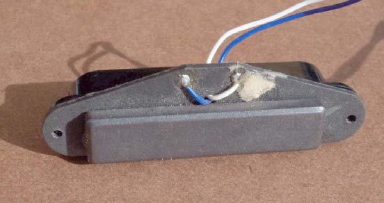
6 White Strat This is a single coil design with 6 common length soft iron rods as pole pieces and a common Ferrite magnet underneath. This is the underside showing the flat ferrite / ceramic bar magnet. The poles of this flat bar magnet are on the large faces (opposite each other). Black Strat Single coil design with 6 common length soft iron rods as pole pieces and a common Ferrite magnet underneath. This is the underside showing the flat ferrite / ceramic bar magnet. The poles of this flat bar magnet are on the large faces (opposite each other). IS INF FRM 001 R1.01 Innovative Synergies Page 6 of 8 Pages


7 Kinman Tele Vertical Hum Bucker coils with what appears like 6 Alnico 5 pole pieces. Kinman Strat Vertical Hum Bucker coils with what appears like 6 Alnico 5 pole pieces. IS INF FRM 001 R1.01 Innovative Synergies Page 7 of 8 Pages


8 Hum Bucker 01 Horizontal Hum Bucker coils with 6 Alnico 5 rod magnets in the main coil and 6 soft iron (Allen Key) rod pole pieces in the bucker coil. A soft iron plate about 2.5 mm thick magnetically joins the coil assemblies. Hum Bucker 02 Horizontal Hum Bucker coils with 6 Alnico 5 rod magnets in the main coil and 6 soft iron (Chrome Plated Raised Head) metal thread screws as rod pole pieces in the bucker coil. A soft iron plate about 2.5 mm thick magnetically joins the coil assemblies. Now that we have a few good pickups let the testing and analysis begin! Copyright Malcolm Moore, Comments and Corrections are welcome IS INF FRM 001 R1.01 Innovative Synergies Page 8 of 8 Pages
14 : TRANSDUCERS I. INTRODUCTION II. FARADAY S LAW OF ELECTROMAGNETIC INDUCTION A. A SINGLE WIRE MOVING IN A MAGNETIC FIELD
 14 : TRANSDUCERS I. INTRODUCTION Transduction is the changing of energy (or information) from one form to another. Microphones transduce acoustical energy into electrical energy (voltage); loudspeakers
Inductors & Resonance
 Inductors & Resonance The Inductor This figure shows a conductor carrying a current. A magnetic field is set up around the conductor as concentric circles. If a coil of wire has a current flowing through
Electrical Theory 2 Lessons for Fall Semester:
 Electrical Theory 2 Lessons for Fall Semester: Lesson 1 Magnetism Lesson 2 Introduction to AC Theory Lesson 3 Lesson 4 Capacitance and Capacitive Reactance Lesson 5 Impedance and AC Circuits Lesson 6 AC
DESIGN, CONSTRUCTION, AND THE TESTING OF AN ELECTRIC MONOCHORD WITH A TWO-DIMENSIONAL MAGNETIC PICKUP. Michael Dickerson
 DESIGN, CONSTRUCTION, AND THE TESTING OF AN ELECTRIC MONOCHORD WITH A TWO-DIMENSIONAL MAGNETIC PICKUP by Michael Dickerson Submitted to the Department of Physics and Astronomy in partial fulfillment of
APPLICATION NOTE - 018
 APPLICATION NOTE - 018 Power Transformers Background Power Transformers are used within an AC power distribution systems to increase or decrease the operating voltage to achieve the optimum transmission
Walchand Institute of Technology. Basic Electrical and Electronics Engineering. Transformer
 Walchand Institute of Technology Basic Electrical and Electronics Engineering Transformer 1. What is transformer? explain working principle of transformer. Electrical power transformer is a static device
Introduction. Inductors in AC Circuits.
 Module 3 AC Theory What you ll learn in Module 3. Section 3.1 Electromagnetic Induction. Magnetic Fields around Conductors. The Solenoid. Section 3.2 Inductance & Back e.m.f. The Unit of Inductance. Factors
describe sound as the transmission of energy via longitudinal pressure waves;
 1 Sound-Detailed Study Study Design 2009 2012 Unit 4 Detailed Study: Sound describe sound as the transmission of energy via longitudinal pressure waves; analyse sound using wavelength, frequency and speed
Device Interconnection
 Device Interconnection An important, if less than glamorous, aspect of audio signal handling is the connection of one device to another. Of course, a primary concern is the matching of signal levels and
July 28, 1959 S. E. LOVER 2,896,49 1
 July 28, 1959 S. E. LOVER 2,896,49 1 MAGNETIC PICKUP FOR STRINGED MUSICAL INSTRUMENT Filed June 22, 1955 2 Sheets-Sheet 1 July 28, 1959 S. E. LOVER 2,896,49 1 MAGNETIC PICKUP FOi! STRING93 MUSICAL INSTRUMENT
INTERNATIONAL BACCALAUREATE PHYSICS EXTENDED ESSAY
 INTERNATIONAL BACCALAUREATE PHYSICS EXTENDED ESSAY Investigation of sounds produced by stringed instruments Word count: 2922 Abstract This extended essay is about sound produced by stringed instruments,
Outcomes from this session
 Outcomes from this session At the end of this session you should be able to Understand what is meant by the term losses. Iron Losses There are three types of iron losses Eddy current losses Hysteresis
The design of Ruthroff broadband voltage transformers M. Ehrenfried G8JNJ
 The design of Ruthroff broadband voltage transformers M. Ehrenfried G8JNJ Introduction I started investigating balun construction as a result of various observations I made whilst building HF antennas.
Single-turn and multi-turn coil domains in 3D COMSOL. All rights reserved.
 Single-turn and multi-turn coil domains in 3D 2012 COMSOL. All rights reserved. Introduction This tutorial shows how to use the Single-Turn Coil Domain and Multi-Turn Coil Domain features in COMSOL s Magnetic
Inductive Sensors. Fig. 1: Geophone
 Inductive Sensors A voltage is induced in the loop whenever it moves laterally. In this case, we assume it is confined to motion left and right in the figure, and that the flux at any moment is given by
Improved Pickup Cover Geometry
 Improved Pickup Cover Geometry (c) Ken Willmott 2016 Background Guitar pickups were introduced early in the 20th century. At that time, early designs were limited by material technology and lack of prior
PHYSICS AND THE GUITAR JORDY NETZEL LAKEHEAD UNIVERSITY
 PHYSICS AND THE GUITAR JORDY NETZEL LAKEHEAD UNIVERSITY 2 PHYSICS & THE GUITAR TYPE THE DOCUMENT TITLE Wave Mechanics Starting with wave mechanics, or more specifically standing waves, it follows then
The 1-hour Electric Broomstick Guitar
 University of Liverpool Dept. Electrical and Electronic Engineering The 1-hour Electric Broomstick Guitar Liverpool Physics Teacher Conference 06/07/2017 Dr Kai Hoettges k.hoettges@liverpool.ac.uk The
LEAKAGE FLUX CONSIDERATIONS ON KOOL Mµ E CORES
 LEAKAGE FLUX CONSIDERATIONS ON E CORES Michael W. Horgan Senior Applications Engineer Magnetics Division of Spang & Co. Butler, PA 163 Abstract Kool Mu, a Silicon-Aluminum-Iron powder, is a popular soft
THE UNDER HUNG VOICE COIL MOTOR ASSEMBLY REVISITED IN THE LARGE SIGNAL DOMAIN BY STEVE MOWRY
 THE UNDER HUNG VOICE COIL MOTOR ASSEMBLY REVISITED IN THE LARGE SIGNAL DOMAIN BY STEVE MOWRY The under hung voice coil can be defined as a voice coil being shorter in wind height than the magnetic gap
A Numerical Study of Depth of Penetration of Eddy Currents
 A Numerical Study of Depth of Penetration of Eddy Currents S.Majidnia* a,b, R.Nilavalan b, J. Rudlin a a. TWI Ltd, Cambridge,United Kingdom b Brunel University, London,United Kingdom shiva.majidnia@twi.co.uk
END-OF-SUBCOURSE EXAMINATION
 END-OF-SUBCOURSE EXAMINATION Circle the letter of the correct answer to each question. When you have answered all of the questions, use a Number 2 pencil to transfer your answers to the TSC Form 59. 1.
A Practical Guide to Free Energy Devices
 A Practical Guide to Free Energy Devices Part PatD21: Last updated: 29th November 2006 Author: Patrick J. Kelly This patent covers a device which is claimed to have a greater output power than the input
Electromagnetic Induction - A
 Electromagnetic Induction - A APPARATUS 1. Two 225-turn coils 2. Table Galvanometer 3. Rheostat 4. Iron and aluminum rods 5. Large circular loop mounted on board 6. AC ammeter 7. Variac 8. Search coil
BALANCED DRIVE. Line of speaker units designed with optimized motor symmetry. The Wavecor Balanced Drive Technology
 BALANCED DRIVE Line of speaker units designed with optimized motor symmetry. The Introduction The Balanced Drive line of loudspeaker transducers is yet another example of Wavecor paying attention to every
ELECTROMAGNETIC INDUCTION AND ALTERNATING CURRENT (Assignment)
") ELECTROMAGNETIC INDUCTION AND ALTERNATING CURRENT (Assignment) 1. In an A.C. circuit A ; the current leads the voltage by 30 0 and in circuit B, the current lags behind the voltage by 30 0. What is the
ELECTROMAGNETIC INDUCTION AND ALTERNATING CURRENT (Assignment) 1. In an A.C. circuit A ; the current leads the voltage by 30 0 and in circuit B, the current lags behind the voltage by 30 0. What is the
THE SINUSOIDAL WAVEFORM
 Chapter 11 THE SINUSOIDAL WAVEFORM The sinusoidal waveform or sine wave is the fundamental type of alternating current (ac) and alternating voltage. It is also referred to as a sinusoidal wave or, simply,
(12) United States Patent (10) Patent No.: US 6,846,981 B2
 United States Patent (10) Patent No.: US 6,846,981 B2") USOO684.6981B2 (12) United States Patent (10) Patent No.: US 6,846,981 B2 Devers (45) Date of Patent: Jan. 25, 2005 (54) ELECTROMAGNETIC HUMBUCKER 5,668,520 A 9/1997 Kinman... 336/84 R PICK-UP FOR STRINGED
USOO684.6981B2 (12) United States Patent (10) Patent No.: US 6,846,981 B2 Devers (45) Date of Patent: Jan. 25, 2005 (54) ELECTROMAGNETIC HUMBUCKER 5,668,520 A 9/1997 Kinman... 336/84 R PICK-UP FOR STRINGED
What is an Inductor? Token Electronics Industry Co., Ltd. Version: January 16, Web:
 Version: January 16, 2017 What is an Inductor? Web: www.token.com.tw Email: rfq@token.com.tw Token Electronics Industry Co., Ltd. Taiwan: No.137, Sec. 1, Zhongxing Rd., Wugu District, New Taipei City,
Sound recording & playback
 Sound recording & playback Dynamic microphone Condenser microphone Carbon microphone Frequency response curves Sound recording Amplifiers Loudspeakers Sound recording & playback - 1 Dynamic microphone
Self-assessment practice test questions Block 4
 elf-assessment practice test questions Block 4 1 A student uses a bar magnet to magnetise an iron wire, as shown in the diagram. he strokes the N pole of the magnet along the length of the wire, and repeats
CHAPTER 5 CONCEPTS OF ALTERNATING CURRENT
 CHAPTER 5 CONCEPTS OF ALTERNATING CURRENT INTRODUCTION Thus far this text has dealt with direct current (DC); that is, current that does not change direction. However, a coil rotating in a magnetic field
Final Publishable Summary
 Final Publishable Summary Task Manager: Dr. Piotr Klimczyk Project Coordinator: Mr. Stefan Siebert Dr. Brockhaus Messtechnik GmbH & Co. KG Gustav-Adolf-Str. 4 D-58507 Lüdenscheid +49 (0)2351 3644-0 +49
Distortion and Power Compression in Low-frequency Transducers
 Technical Notes Volume 1, Number 9 Distortion and Power Compression in Low-frequency Transducers 1 Introduction: All too often, consultants and sound contractors are concerned with only the Input power
Inductors, Chokes, Reactors, Filters
 Inductors, Chokes, Reactors, Filters What s in a name? Author: Anthony J. Kourtessis 2 Inductors, Chokes, Reactors, Filters What s in a name? These ubiquitous terms are familiar to most engineers and are
REQUIRED SKILLS AND KNOWLEDGE UEENEEG101A. Electromagnetic devices and circuits. Topic and Description NIDA Lesson CARD # Magnetism encompassing:
 REQUIRED SKILLS AND KNOWLEDGE UEENEEG101A KS01-EG101A Electromagnetic devices and circuits T1 Magnetism encompassing: Topic and Description NIDA Lesson CARD # magnetic field pattern of bar and horse-shoe
A STUDY ON NOISE REDUCTION OF AUDIO EQUIPMENT INDUCED BY VIBRATION --- EFFECT OF MAGNETISM ON POLYMERIC SOLUTION FILLED IN AN AUDIO-BASE ---
 A STUDY ON NOISE REDUCTION OF AUDIO EQUIPMENT INDUCED BY VIBRATION --- EFFECT OF MAGNETISM ON POLYMERIC SOLUTION FILLED IN AN AUDIO-BASE --- Masahide Kita and Kiminobu Nishimura Kinki University, Takaya
EC-5 MAGNETIC INDUCTION
 EC-5 MAGNETIC INDUCTION If an object is placed in a changing magnetic field, or if an object is moving in a non-uniform magnetic field in such a way that it experiences a changing magnetic field, a voltage
Books by Dieter Stotz (among many other publications):
:") Dieter Stotz works since many years as a hardware engineer and developer especially in sensor technologies for measuring systems of the food industry. Furthermore he is an expert in Audio- and Videotechnology
Dieter Stotz works since many years as a hardware engineer and developer especially in sensor technologies for measuring systems of the food industry. Furthermore he is an expert in Audio- and Videotechnology
VARIABLE INDUCTANCE TRANSDUCER
 VARIABLE INDUCTANCE TRANSDUCER These are based on a change in the magnetic characteristic of an electrical circuit in response to a measurand which may be displacement, velocity, acceleration, etc. 1.
Wimborne Publishing, reproduce for personal use only
 In part 1 we looked at some of the principles involved with measuring magnetic fields. This time, we take a more practical approach and look at some experimental circuits. The circuits illustrated are
Knowledge Integration Module 2 Fall 2016
 Knowledge Integration Module 2 Fall 2016 1 Basic Information: The knowledge integration module 2 or KI-2 is a vehicle to help you better grasp the commonality and correlations between concepts covered
Induction heating of internal
 OPTIMAL DESIGN OF INTERNAL INDUCTION COILS The induction heating of internal surfaces is more complicated than heating external ones. The three main types of internal induction coils each has its advantages
(12) Patent Application Publication (10) Pub. No.: US 2005/ A1
 Patent Application Publication (10) Pub. No.: US 2005/ A1") (19) United States US 2005O156702A1 (12) Patent Application Publication (10) Pub. No.: US 2005/0156702 A1 Marshall (43) Pub. Date: Jul. 21, 2005 (54) MOTIONLESS ELECTROMAGNETIC TURBINE (76) Inventor: Eric
(19) United States US 2005O156702A1 (12) Patent Application Publication (10) Pub. No.: US 2005/0156702 A1 Marshall (43) Pub. Date: Jul. 21, 2005 (54) MOTIONLESS ELECTROMAGNETIC TURBINE (76) Inventor: Eric
The practicalities of measuring fast switching currents in power electronics using Rogowski probes
 The practicalities of measuring fast switching currents in power electronics using Rogowski probes Dr Chris Hewson Director, PEM Ltd Booth No. 418 About PEM Ltd Power Electronic Measurements Ltd (PEM)
Advanced electromagnetism and electromagnetic induction
 Advanced electromagnetism and electromagnetic induction This worksheet and all related files are licensed under the Creative Commons Attribution License, version 1.0. To view a copy of this license, visit
CHAPTER 5 Test B Lsn 5-6 to 5-8 TEST REVIEW
 IB PHYSICS Name: Period: Date: DEVIL PHYSICS BADDEST CLASS ON CAMPUS CHAPTER 5 Test B Lsn 5-6 to 5-8 TEST REVIEW 1. This question is about electric circuits. (a) (b) Define (i) (ii) electromotive force
1 K Hinds 2012 TRANSFORMERS
 1 K Hinds 2012 TRANSFORMERS A transformer changes electrical energy of a given voltage into electrical energy at a different voltage level. It consists of two coils which are not electrically connected,
Module 9. DC Machines. Version 2 EE IIT, Kharagpur
 Module 9 DC Machines Lesson 35 Constructional Features of D.C Machines Contents 35 D.C Machines (Lesson-35) 4 35.1 Goals of the lesson. 4 35.2 Introduction 4 35.3 Constructional Features. 4 35.4 D.C machine
Sound 05/02/2006. Lecture 10 1
 What IS Sound? Sound is really tiny fluctuations of air pressure units of pressure: N/m 2 or psi (lbs/square-inch) Carried through air at 345 m/s (770 m.p.h) as compressions and rarefactions in air pressure
GEOMETRICS technical report
 GEOMETRICS technical report MA-TR 15 A GUIDE TO PASSIVE MAGNETIC COMPENSATION OF AIRCRAFT A fixed installation of a total field magnetometer sensor on an aircraft is much more desirable than the towed
Testing Critical Medical Tubing Using High Frequency Eddy Current Coils
 Testing Critical Medical Tubing Using High Frequency Eddy Current Coils Troy M Libby Magnetic Analysis Corporation, Mt. Vernon, NY, USA Phone: (914) 699-9450, Fax: (914) 699-9837; e-mail: info@mac-ndt.com
Power Transformers. Energy Systems Research Laboratory, FIU
 Power Transformers By: Alberto Berzoy Energy Systems Research Laboratory Department of Electrical & Computer Engineering Florida International University Miami, Florida, USA Overview 2 Introduction Transformer
University of Jordan School of Engineering Electrical Engineering Department. EE 219 Electrical Circuits Lab
 University of Jordan School of Engineering Electrical Engineering Department EE 219 Electrical Circuits Lab EXPERIMENT 4 TRANSIENT ANALYSIS Prepared by: Dr. Mohammed Hawa EXPERIMENT 4 TRANSIENT ANALYSIS
In both cases the pickups are located in cavities prepared in the body of the instrument.
 May 2016 Howdy! In this Tech Tips Newsletter I would like to focus on the mechanical requirements associated with installing new pickups into Stratocaster style instruments. Summary: The mechanical installation
Properties of Waves, Magnetism, & Electricity Unit 4 Summative Assessment
 1. When a sound wave travels through a medium, what is being transmitted in the direction of the movement of the wave? density mass energy velocity 2. An iron rod changes colors when heated in a hot flame.
Comprehensive Study on Magnetization Current Harmonics of Power Transformers due to GICs
 Comprehensive Study on Magnetization Current Harmonics of Power Transformers due to GICs S. A. Mousavi, C. Carrander, G. Engdahl Abstract-- This paper studies the effect of DC magnetization of power transformers
Goals. Introduction. To understand the use of root mean square (rms) voltages and currents.
 voltages and currents.") Lab 10. AC Circuits Goals To show that AC voltages cannot generally be added without accounting for their phase relationships. That is, one must account for how they vary in time with respect to one another.
Lab 10. AC Circuits Goals To show that AC voltages cannot generally be added without accounting for their phase relationships. That is, one must account for how they vary in time with respect to one another.
Electric Guitar Kit DC Style electric guitar kit
 Electric Guitar Kit DC Style electric guitar kit user manual Musikhaus Thomann Thomann GmbH Hans-Thomann-Straße 1 96138 Burgebrach Germany Telephone: +49 (0) 9546 9223-0 E-mail: info@thomann.de Internet:
Baritone. Noticeably Finer Musical Instruments. Baritone. Specifications
 Noticeably Finer Musical Instruments Specifications Scale - 29.858" (9" fingerboard radius) Neck Width - 1 5/8" at nut, 2 1/8" at 22nd fret Fingerboard - Pau Ferro or Maple (jumbo frets) Neck - Eastern
INDUCTOR. Inductors are electronic components that oppose a change in current. Air Core Inductor Symbol
 BASIC ELECTRICAL INDUCTOR INTRODUCTION are used for their ability to lter high frequencies out of the audio in a sound system. As an introduction to the focus of this lesson will be to discuss the different
Definitions. Spectrum Analyzer
 SIGNAL ANALYZERS Spectrum Analyzer Definitions A spectrum analyzer measures the magnitude of an input signal versus frequency within the full frequency range of the instrument. The primary use is to measure
OPTIMIZATION OF AN INDUCTION COIL FOR ULF
 OPTIMIZATION OF AN INDUCTION COIL FOR ULF This paper is to dimostrate how to is possible to optimize an induction coil for ULF band (0.1-30Hz). My realization was inspire to Hans Michlmayr project. My
Fireball. Noticeably Finer Musical Instruments. Specifications
 Noticeably Finer Musical Instruments Specifications Scale - 25.064" (9" fingerboard radius) Neck Width - 1 11/16" at nut, 2 1/8" at 22nd fret Fingerboard - Pau Ferro or Maple (jumbo frets) Neck - Eastern
3. What is hysteresis loss? Also mention a method to minimize the loss. (N-11, N-12)
") DHANALAKSHMI COLLEGE OF ENGINEERING, CHENNAI DEPARTMENT OF ELECTRICAL AND ELECTRONICS ENGINEERING EE 6401 ELECTRICAL MACHINES I UNIT I : MAGNETIC CIRCUITS AND MAGNETIC MATERIALS Part A (2 Marks) 1. List
DHANALAKSHMI COLLEGE OF ENGINEERING, CHENNAI DEPARTMENT OF ELECTRICAL AND ELECTRONICS ENGINEERING EE 6401 ELECTRICAL MACHINES I UNIT I : MAGNETIC CIRCUITS AND MAGNETIC MATERIALS Part A (2 Marks) 1. List
SPH3U UNIVERSITY PHYSICS
 SPH3U UNIVERSITY PHYSICS ELECTRICITY & MAGNETISM L Faraday s Discovery (P.588-591) Faraday s Discovery In 1819, when Oersted demonstrated the ability of a steady current to produce a steady magnetic field,
R. W. Erickson. Department of Electrical, Computer, and Energy Engineering University of Colorado, Boulder
 R. W. Erickson Department of Electrical, Computer, and Energy Engineering University of Colorado, Boulder 13.2.3 Leakage inductances + v 1 (t) i 1 (t) Φ l1 Φ M Φ l2 i 2 (t) + v 2 (t) Φ l1 Φ l2 i 1 (t)
1. Position detection on a spindle drive unit by means of a linear potentiometer
 Displacement measurements 1. Position detection on a spindle drive unit by means of a linear potentiometer Learning contents: Mechanical assembly and electrical connection of a spindle drive unit Mechanical
Department of Electrical and Computer Engineering Lab 6: Transformers
 ESE Electronics Laboratory A Department of Electrical and Computer Engineering 0 Lab 6: Transformers. Objectives ) Measure the frequency response of the transformer. ) Determine the input impedance of
Bandit. Noticeably Finer Musical Instruments
 Noticeably Finer Musical Instruments Specifications Scale - 25.064" (9" fingerboard radius) Neck Width - 1 11/16" at nut, 2 1/8" at 22nd fret Fingerboard - Pau Ferro or Maple (jumbo frets) Neck - Eastern
Generator Advanced Concepts
 Generator Advanced Concepts Common Topics, The Practical Side Machine Output Voltage Equation Pitch Harmonics Circulating Currents when Paralleling Reactances and Time Constants Three Generator Curves
SECTION A Waves and Sound
 AP Physics Multiple Choice Practice Waves and Optics SECTION A Waves and Sound 1. Which of the following statements about the speed of waves on a string are true? I. The speed depends on the tension in
total j = BA, [1] = j [2] total
![total j = BA, [1] = j [2] total](/thumbs/85/91692343.jpg "total j = BA, [1] = j [2] total") Name: S.N.: Experiment 2 INDUCTANCE AND LR CIRCUITS SECTION: PARTNER: DATE: Objectives Estimate the inductance of the solenoid used for this experiment from the formula for a very long, thin, tightly wound
Name: S.N.: Experiment 2 INDUCTANCE AND LR CIRCUITS SECTION: PARTNER: DATE: Objectives Estimate the inductance of the solenoid used for this experiment from the formula for a very long, thin, tightly wound
Large Kool Mµ Core Shapes
 Large Kool Mµ Core Shapes TECHNICAL BULLETIN Ideal for high current inductors, large Kool Mµ geometries (E cores, U Cores and Blocks) offer all the advantages of Kool Mµ material, low core loss, excellent
Waves Homework. Assignment #1. Assignment #2
 Waves Homework Assignment #1 Textbook: Read Section 11-7 and 11-8 Online: Waves Lesson 1a, 1b, 1c http://www.physicsclassroom.com/class/waves * problems are for all students ** problems are for honors
I p = V s = N s I s V p N p
 UNIT G485 Module 1 5.1.3 Electromagnetism 11 For an IDEAL transformer : electrical power input = electrical power output to the primary coil from the secondary coil Primary current x primary voltage =
Review 6. unlike poles cause the magnets to attract. like poles cause the magnets to repel.
 Review 6 1. The two characteristics of all magnets are: they attract and hold Iron, and, if free to move, they will assume roughly a south - north position. 2. Lines of flux always leave the north pole
Electromagnetic Induction
 Chapter 16 Electromagnetic Induction In This Chapter: Electromagnetic Induction Faraday s Law Lenz s Law The Transformer Self-Inductance Inductors in Combination Energy of a Current-Carrying Inductor Electromagnetic
Unit FE-5 Foundation Electricity: Electrical Machines
 Unit FE-5 Foundation Electricity: Electrical Machines What this unit is about Power networks consist of large number of interconnected hardware. This unit deals specifically with two types of hardware:
Electromagnet Motor Generator
 Magnetism and Electromagnetic Induction Study Guide Chapter 36 & 37 Key Terms: Magnetic Pole Magnetic Field Magnetic Domain Electromagnet Motor Generator Electromagnetic Induction Faraday s Law Transformer
End-of-Chapter Exercises
 End-of-Chapter Exercises Exercises 1 12 are primarily conceptual questions designed to see whether you understand the main concepts of the chapter. 1. The four areas in Figure 20.34 are in a magnetic field.
MAGNETOSCOP Measurement of magnetic field strengths in the range 0.1 nanotesla to 1 millitesla
 MAGNETOSCOP Measurement of magnetic field strengths in the range 0.1 nanotesla to 1 millitesla Extremely high sensitivity of 0.1 nanotesla with field and gradient probe Measurement of material permeabilities
Using the V5.x Integrator
 Using the V5.x Integrator This document explains how to produce the Bode plots for an electromagnetic guitar pickup using the V5.x Integrator. Equipment: Test coil 50-100 turns of 26 AWG coated copper
12. Electromagnetic Induction
 Leaving Cert Physics Long Questions: 2017-2002 12. Electromagnetic Induction Please remember to photocopy 4 pages onto one sheet by going A3 A4 and using back to back on the photocopier Contents Electromagnetic
Glossary of Common Magnetic Terms
 Glossary of Common Magnetic Terms Copyright by Magnelab, Inc. 2009 Air Core A term used when no ferromagnetic core is used to obtain the required magnetic characteristics of a given coil. (see Core) Ampere
Large Kool Mµ Core Shapes
 Large Kool Mµ Core Shapes TECHNICAL BULLETIN Ideal for high current inductors, large Kool Mµ geometries (E cores, U Cores and Blocks) offer all the advantages of Kool Mµ material, low core loss, excellent
No Brain Too Small PHYSICS
 ELECTRICITY: AC QUESTIONS No Brain Too Small PHYSICS MEASURING IRON IN SAND (2016;3) Vivienne wants to measure the amount of iron in ironsand mixtures collected from different beaches. The diagram below
9/28/2010. Chapter , The McGraw-Hill Companies, Inc.
 Chapter 4 Sensors are are used to detect, and often to measure, the magnitude of something. They basically operate by converting mechanical, magnetic, thermal, optical, and chemical variations into electric
Large Kool Mµ Core Shapes
 Large Kool Mµ Core Shapes Technical Bulletin Ideal for high current inductors, large Kool Mµ geometries (E cores, Toroids, U Cores and Blocks) offer all the advantages of Kool Mµ material, low core loss,
(c) In the process of part (b), must energy be supplied to the electron, or is energy released?
 In the process of part (b), must energy be supplied to the electron, or is energy released?") (1) A capacitor, as shown, has plates of dimensions 10a by 10a, and plate separation a. The field inside is uniform, and has magnitude 120 N/C. The constant a equals 4.5 cm. (a) What amount of charge is
(1) A capacitor, as shown, has plates of dimensions 10a by 10a, and plate separation a. The field inside is uniform, and has magnitude 120 N/C. The constant a equals 4.5 cm. (a) What amount of charge is
Study of Plasma Equilibrium during the AC Current Reversal Phase on the STOR-M Tokamak
 1 Study of Plasma Equilibrium during the AC Current Reversal Phase on the STOR-M Tokamak C. Xiao 1), J. Morelli 1), A.K. Singh 1, 2), O. Mitarai 3), T. Asai 1), A. Hirose 1) 1) Department of Physics and
Inductance in DC Circuits
 Inductance in DC Circuits Anurag Srivastava Concept: Inductance is characterized by the behavior of a coil of wire in resisting any change of electric current through the coil. Arising from Faraday's law,
Published in: Proceedings of the 29th Annual IEEE Applied Power Electronics Conference and Exposition, APEC 2014.
 Aalborg Universitet Method for introducing bias magnetization in ungaped cores Aguilar, Andres Revilla; Munk-Nielsen, Stig Published in: Proceedings of the 29th Annual IEEE Applied Power Electronics Conference
Laminate Transformer Testing
 1. Introduction: Laminate transformers are mostly used as line frequency, low frequency and low/high voltage step-up, step-down transformers. Two coils are wound over a core such that they are magnetically
Investigating Electromagnetic and Acoustic Properties of Loudspeakers Using Phase Sensitive Equipment
 Investigating Electromagnetic and Acoustic Properties of Loudspeakers Using Phase Sensitive Equipment Katherine Butler Department of Physics, DePaul University ABSTRACT The goal of this project was to
NCERT solution for Sound
 NCERT solution for Sound 1 Question 1 How does the sound produce by a vibrating object in a medium reach your ear? When an object vibrates, it vibrates the neighboring particles of the medium. These vibrating
FGM-series Magnetic Field Sensors
 Speake & Co. Limited Distributed in the United States by Fat Quarters Software 24774 Shoshonee Drive Murrieta, California 92562 USA Tel: 951-69-7950 Fax: 951-69-7913 FGM-series Magnetic Field Sensors +5
Telemetrie-Messtechnik Schnorrenberg
 Telemetrie-Messtechnik Schnorrenberg MTP-IND-PWR User Manual Inductive power supply set Power supply for power head 25 and 50mm mounting tape to fix coil on shaft Ferrite tape 30mmx3m CUL 1.00 mm (Enamelled
Physics in Entertainment and the Arts
 Physics in Entertainment and the Arts Chapter VIII Control of Sound The sound characteristics (acoustics) of a room depend upon a great many complex factors room size/shape wall/floor/ceiling materials