(12) Patent Application Publication (10) Pub. No.: US 2005/ A1
|
|
|
- Laurence Gardner
- 6 years ago
- Views:
Transcription
 MOTIONLESS ELECTROMAGNETIC TURBINE (76) Inventor: Eric Giles Marshall, Harrison Hot Springs (CA) Correspondence Address: ERIC GILES MARSHALL 217,378 ESPLANADEAVENUE HARRISON HOT")
1 (19) United States US 2005O156702A1 (12) Patent Application Publication (10) Pub. No.: US 2005/ A1 Marshall (43) Pub. Date: Jul. 21, 2005 (54) MOTIONLESS ELECTROMAGNETIC TURBINE (76) Inventor: Eric Giles Marshall, Harrison Hot Springs (CA) Correspondence Address: ERIC GILES MARSHALL 217,378 ESPLANADEAVENUE HARRISON HOT SPRINGS, BC V0M 1KO (CA) (21) Appl. No.: 10/759,829 (22) Filed: Jan. 20, 2004 Publication Classification (51) Int. Cl.... H01F 27/24 (52) U.S. Cl /214 (57) ABSTRACT An electromagnetic turbine without moving parts includes a magnetic core with three magnetic paths and magnetic connectors arranged between the three paths forming two adjacent closed magnetic loops. Three coils extend individu ally around portions of each magnetic path. The three coils are electrically pulsed to provide current pulses in the coils. Driving electrical current through each of the coils in sequence results in a flow of magnetic flux external to the magnetic core. The sequence is arranged to create a con tinuous one-way flow of magnetic flux through the inside of the core, then out one end where the flux extends outward and sweeps external to the core to the opposite end of the core where the flux collapses into the core. The Sweeping magnetic flux induces electrical currents into electrically conductive material external to and not part of the turbine. Magnetic flux from the external currents interacts with the sweeping flux, resulting in a net force. The force either absorbs energy from relative deceleration of external mate rial, converting the deceleration to electrical energy; Or electrical energy provides relative acceleration of external material, converting the electrical energy to acceleration.

2 Patent Application Publication Jul. 21, 2005 Sheet 1 of 9 US 2005/ A1 Fig. 1
3 Patent Application Publication Jul. 21, 2005 Sheet 2 of 9 Fig. 3 US 2005/ A1
4
5
6
7 Fig. 6a 7 tly p -- YES or Fig. 6b
8
9

10 Patent Application Publication Jul. 21, 2005 Sheet 9 of 9 US 2005/ A1 I ---

11 US 2005/ A1 Jul. 21, 2005 MOTIONLESS ELECTROMAGNETIC TURBINE BACKGROUND INFORMATION 0001) 1. Field of Invention 0002 This invention relates to an electromagnetic turbine used to convert electrical power to relative motion without moving parts, and, more particularly, to Such a device having a capability, when operating, of converting electrical power to relative movement in material external to, and not part of the turbine. In Similar fashion, the same electromagnetic turbine without moving parts can also be used to convert relative movement from material external to and not part of the turbine, to electrical power Description of the Related Art The patent literature describes a number of mag netic motors and generators, including permanent magnets and/or electromagnets, magnetic paths and magnetic con ductors forming magnetic loops. Each magnetic loop extends between the opposite poles of permanent magnets and/or electromagnets, with electrical Switching means for causing magnetic flux to flow in Sequence along the mag netic paths. The magnetic paths are Surrounded by one or more coils in which electrical current is induced to flow either by application of external electrical inputs or by changes in the magnetic flux within the device. These devices operate in accordance with Faraday's Law, indicat ing that an electrical current induces a magnetic field that Surrounds a conductor and that an electrical current is induced into a conductor within a changing magnetic field On Mar. 26, 2002, U.S. Pat. No. 6,362,718 was granted to Patrick, et al, which is incorporated herein by reference. The patent describes a motionless electromag netic generator, comprising an electromagnetic generator without moving parts consisting of a magnetic core includ ing first and Second magnetic paths and a permanent magnet in the center forming two adjacent closed magnetic loops. A first input coil and a first output coil extend around portions of the first magnetic path, while a Second input coil and a Second output coil extend around portions of the Second magnetic path. The input coils are alternatively pulsed to provide induced current pulses in the output coils. Driving electrical current through each of the input coils reduces a level of flux from the permanent magnet within the magnet path around which the input coil extends, forcing the flux to Sweep external to the core, toggling back and forth between the alternate paths. The patent contends that by tuning the frequency and intensity of the toggling action, the Sweeping flux absorbs energy from the external environment, resulting in a net generation of electricity. How the toggling action of the Sweeping flux absorbs external energy and converts it to electricity is unclear Since there apparently is no relative net motion change and therefore no net acceleration or decel eration of material external to the generator. The permanent magnet in the center magnetic path, permanently holds the State of magnetic flux in the center path, preventing flux flow through the inside of the core. By comparison, my invention does not contain a permanent magnet in the center path, but rather contains a coil allowing bipolar control of flux in the center path, and therefore bi-directional control of flux flow inside the core. This difference is significant and differen tiates my invention by allowing continuous and controllable flux flow in the device, key to efficient operation as a motor or a generator. Furthermore, the addition of a coil around the center path obviates the need for So-called input or control coils Surrounding portions of the first and Second path The patent of Patrick, et al, also contains numerous references to prior art, all Supporting the basic fundamentals by which the device operates, but none conflicting within the Scope and claims of the device. In Similar fashion those same references Support the basic fundamentals by which the present invention operates, but none conflicting within the Scope and claims of the present invention. Those numerous references to prior art, by association are hereby incorpo rated herein On Jun. 15, 1993 I filed an application for patent with the USPTO titled: O008) AN ELECTROMOTIVE APPARATUS HAVING A FIRST COMPONENT MOVABLE IN RELATION TO ASECOND COMPONENT 0009 Ser. No. 08/076,844 was assigned. This application was eventually abandoned On Jul. 9, 1997 I re-filed the application with the USPTO, with new information and a new title: 0011) LATERAL POLE SPACING vs MAGNETIC SHORT CIRCUITS IN ELECTROMOTIVE DEVICES 0012 Ser. No. 08/890,407 was assigned. This application was also eventually abandoned On Dec. 9, 2002 I filed a different but related application for patent with the USPTO titled: 0014) HIGH TORQUE BRUSHLESS DC MOTORS AND GENERATORS Ser. No. 10/313,889 was assigned. This application is still pending and most recent correspondence confirmation number 8233 was received These references to my former related patent appli cations are included to illustrate my immense commitment to and thorough understanding of related Subject matter. These former applications refer individually and inclusively to three phase electromechanical motors, generators, and three phase electronic inverters capable of generating and regenerating three phase Sine waves or quasi-sine waves. The pending application Ser. No. 10/313,889 illustrates geometric relationships eliminating magnetic short circuits and providing Sine wave output waveforms with axially extended rotors and Stators in three phase electromechanical motors and generators. The pending application also illus trates three phase bidirectional buck-boost pulse width modulation control circuits, permanent magnet concentra tion applied to three phase permanent magnet motors and generators, back-emf rotor position Sensing, and Hall Effect magnetic Sensing to enhance electronic Switching precision in three phase motors. Finally, the pending appli cation also illustrates a speed independent rotating trans former inductive coupling mechanism for regulating rotor field excitation power, that performs a similar function to brushes and Slip rings in a three phase electromechanical motor or generator, but without mechanical contact. I hereby State and confirm that I independently conceived, fabricated, and tested the electromechanical mechanisms, electronic circuits, and electrical apparatus in the prior and pending

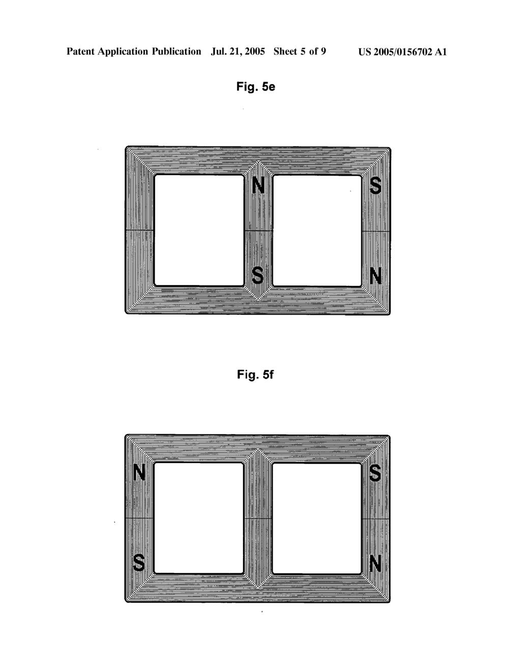
12 US 2005/ A1 Jul. 21, 2005 inventions. It will be obvious to one skilled in the art that the present invention represents a culmination of the inventive process. It will also be obvious that the three phase electro mechanical generators and motors, three phase electronic inverters, and other electrical apparatus represented in my prior and pending patent applications, will work with, pro vide appropriate electrical power to, or accept electrical power from, the apparatus of the present invention. SUMMARY OF THE INVENTION It is a first objective of the present invention to provide a magnetic turbine that exerts a net force resulting in relative movement in material external to and not part of the turbine, converting electrical energy to relative motion It is a second objective of the present invention to provide a magnetic turbine that exerts a net force resulting from relative movement in material external to and not part of the turbine, converting relative motion to electrical energy It is a third objective of the present invention to provide a magnetic turbine in which a net force exerted in material external to and not part of the turbine is accom plished without moving parts In the apparatus of the present invention, the path of the magnetic fields in the magnetic core is Switched in a manner resulting in a flow of magnetic flux within the magnetic core. The Sequence is arranged to create a con tinuous one-way flow of magnetic flux through the inside of the core, then out one end where the flux extends outward and Sweeps external to the core to the opposite end where the flux collapses into the core. The Sweeping magnetic flux induces electrical currents into electrically conductive mate rial external to and not part of the turbine. Magnetic flux from the external currents interacts with the Sweeping flux, resulting in a net force According to the first objective of the present invention, an electromagnetic motor is provided, including a magnetic core with three magnetic paths and magnetic connectors arranged between the three paths forming two adjacent closed magnetic loops. Three coils extend individu ally around portions of each magnetic path. The three coils are electrically pulsed to provide current pulses in the coils. Driving electrical current through each of the coils in Sequence results in a flow of magnetic flux external to the magnetic core. Timing of the pulses results in external magnetic flux Sweeping faster than the relative movement of the electrically conductive material external to the turbine. The Sweeping magnetic flux induces electrical currents into electrically conductive material external to the turbine inducing a magnetic flux that opposes the motion of the Sweeping flux, resulting in a net propulsive acceleration According to a second objective of the present invention, an electromagnetic generator is provided, includ ing a magnetic core with three magnetic paths and magnetic connectors arranged between the three paths forming two adjacent closed magnetic loops. Three coils extend individu ally around portions of each magnetic path. The three coils are electrically pulsed to provide current pulses in the coils. Driving electrical current through each of the coils in Sequence results in a flow of magnetic flux external to the magnetic core. The Sweeping magnetic flux induces electri cal currents into electrically conductive material external to the turbine inducing a magnetic flux that reinforces the motion of the Sweeping flux. Timing of the pulses results in the external Sweeping flux decelerating the relative move ment of the electrically conductive material external to the turbine, resulting in an acceleration of flux flow in the core and a net generation of electrical energy in the coils According to a third objective of the present inven tion, an electromagnetic turbine without moving parts is provided, including a magnetic core with three magnetic paths and magnetic connectors arranged between the three paths forming two adjacent closed magnetic loops. Three coils extend individually around portions of each magnetic path. The three coils are electrically pulsed to provide current pulses in the coils. Driving electrical current through each of the coils in Sequence results in a flow of magnetic flux external to the magnetic core. The Sweeping magnetic flux induces electrical currents into electrically conductive material external to the core. Magnetic flux from the external currents interacts with the Sweeping flux, resulting in a net accelerating or decelerating force, without moving parts. BRIEF DESCRIPTION OF THE DRAWINGS 0024 FIG. 1 is a partly schematic cross-sectional front View of a magnetic turbine and associated electrical circuits built in accordance with an embodiment of the present invention FIG.2 is a graphical view of three phase sine wave electrical Signals driven into or produced by the apparatus of FIG FIG. 3 is a schematic view of the magnetic turbine and associated electrical circuits of FIG FIG. 4 is a graphical view of three phase quasi-sine wave electrical Signals driven into or produced by the apparatus of FIG FIGS. 5a-5f are partly schematic cross-sectional front views illustrating Sequential magnetic States in the apparatus of FIG FIGS. 6a-6f are partly schematic cross-sectional front views illustrating Sequential magnetic transitions in and external to the apparatus of FIG FIG. 7 is a partly schematic cross-sectional front View illustrating magnetic flux flow in and external to the apparatus of FIG. 1. DETAILED DESCRIPTION OF THE INVENTION 0031 FIG. 1 is a partly schematic cross-sectional front View of an electromagnetic turbine, and associated magnetic core 1 with protective insulating coating 2 and electrical coils 7, 8, 9 built in accordance with an embodiment of the present invention. The flux core material 1 is configured to form three magnetic paths and two adjacent closed magnetic loops, the three coils 7, 8, 9 extending individually around portions of each magnetic path. The three magnetic paths contain butt joints 3 that allows assembly of cut core 1 after the coils 7, 8, 9 are wound on bobbins 4. An alternative embodiment with uncut core 1 requires more difficult wind ing of coils 7, 8, 9 on split bobbins 4 between the two adjacent closed magnetic loops. Positively phased ends of

13 US 2005/ A1 Jul. 21, 2005 coils 7, 8, 9 indicated by '+' signs have their external electrical connections indicated by letters A, B, C respectively. Negatively phased ends of coils 7, 8, 9 are joined at electrical splice 5 with leads FIG. 2 is a graphical view of electrical signals driven into or produced by the apparatus of FIG. 1 repre sented by the schematic of FIG. 3. Letters A, B, C of FIG. 2 represent electrical connections to coils 7, 8, 9 through letters A, B, C of FIG. 1 and FIG. 3. The Vertical hairline represents an instant in time by which the three electrical signals A, B, C are synchronized, with time proceeding Synchronously to the right. Three horizontal hairlines indicate Zero for each electrical Signal, with relative positive electrical potential proceeding upward and relative negative electrical potential proceeding downward. The tim ing of the Signals is Such that each Signal leads or lags the other two Signals in time by equal amounts. One skilled in the art will recognize FIG. 2 as a representation of a three-phase Sine wave typical of a three-phase electrome chanical generator or of an electronically Switched three phase inverter with pulse width modulation control FIG. 3 is a schematic representation of the elec tromagnetic turbine of FIG. 1, with associated magnetic core 1, protective insulating coating 2 and electrical coils 7, 8, 9. Positively phased ends of coils 7, 8, 9 indicated by + Signs have their external electrical connections indicated by letters A, B, C respectively. Negatively phased ends of coils 7, 8, 9 are joined at electrical splice 5 with leads FIG. 4 is a graphical view of electrical signals driven into the apparatus of FIG. 1 represented by the schematic of FIG.3. Letters A, B, C of FIG. 4 represent electrical connections to coils 7, 8, 9 through letters 'A', 'B', *C. of FIG. 1 and FIG.3. The vertical hairline represents an instant in time by which the three electrical signals A, B, C are Synchronized, with time proceeding Synchronously to the right. Three horizontal hairlines indicate Zero for each electrical Signal, with relative positive electrical potential proceeding upward and relative negative electrical potential proceeding downward. The timing of the Signals is Such that each Signal leads or lags the other two signals in time by equal amounts. One skilled in the art will recognize FIG. 2 as a representation of a three-phase quasi-sine wave typical of an electronically Switched three-phase inverter without pulse width modulation control FIGS. 5a-5fare partial schematic representations of sequential magnetic states and FIGS. 6a-6f are partial Schematic representations of Sequential magnetic transitions in the apparatus of FIG. 1 with magnetic pole orientation indicated by the letters 'N' and 'S' for respective north and South magnetic poles. For clarity, the magnetic orientation is arbitrarily defined as proceeding vertically from top to bottom where a north to South orientation is represented as N-S FIG.5a arbitrarily illustrates the first state with left path oriented N-S, center path S-N, and right path neutral. FIG. 6a illustrates the first transition with electrical inputs arranged to neutralize magnetic flux in the left path, hold flux constant in the center path, and attract flux into the right path. The flux is forced to extend outward from the left path, and Sweep external to the core to the right Side where it collapses into the right path. After the first transition, the second state of FIG. 5b is attained with left path neutral, center path S-N, and right path N-S. FIG. 6b illustrates the Second transition with electrical inputs arranged to neutralize flux in center path, hold flux constant in right path, and attract flux into left path. The flux is forced to extend left from the center path, forcing the flux inside the left core loop to the left side, where it collapses into the left path. After the Second transition, the third state of FIG. 5c is attained with center path neutral, left path S-N, and right path N-S. FIG. 6c illustrates the third transition with electrical inputs arranged to neutralize flux in right path, hold flux constant in left path, and attract flux into center path. The flux is forced to extend left from the right path, forcing the flux inside the right core loop to the center, where it collapses into the center path. After the third transition, the fourth state of FIG. 5d is attained with right path neutral, left path S-N, and center path N-S. FIGS. 5d-5f and 6d-6fillustrate states and transitions 4, 5, 6 Similar to States and transitions 1, 2, 3, except with opposite polarities. After the Sixth transition, the state reverts to the original first state of FIG. 5a where the Sequence continues. It will be obvious to Someone skilled in the art that reversing the Sequence, or Swapping two signal phases will reverse the flow of magnetic flux FIG. 7 is a partial schematic representation of net magnetic flux flow in and external to the apparatus of FIG. 1. When the apparatus is operating in proper Sequence, magnetic flux 10 flows continuously through the inside of core 1 and then Sweeps external to the core 1 according to a path of similar flux energy illustrated by ellipsoid 11. The flux external to the core is leveraged in reference to a magnetic pivot point inside the core causing the impulse of magnetic flux Sweeping at a distance from the core to be faster than the impulse of the flux within the core. The leveraging ratio is proportional to the distance between the magnetic pivot point and the material that the Sweeping flux is interacting with, and the distance between the pivot point and the flux impulse in the core. The external flux impulse Speed is a product of the flux impulse Speed in the core and the leveraging ratio. AS magnetic flux has no mass, it is shown that as the frequency of the electrical Signal increases from kilohertz and megahertz to gigahertz, the impulse Speed within the core will increase proportionately, limited by properties of the core, coils, electronic Switches, and available electrical power. It is also shown that the Sweeping flux extends out to infinity with the energy density of the flux diminished proportional to the distance from the core. Despite the flux energy density being diminished with distance from the core, the possibility exists for the Sweep ing flux impulse to achieve exceedingly high Speeds, well beyond any prior art propulsion mechanism. Indeed, as the flux impulse Speed within the core approaches the Speed of light, also known as the impulse Speed of transverse elec tromagnetic compression waves, at a distance the external flux impulse speed will be proportionately faster by the previously illustrated leveraging ratio. Therefore, as the external distance increases, and the flux impulse within the core approaches the Speed of light, the external flux impulse Speed goes well beyond the Speed of light In accordance with a preferred embodiment of the present invention, the coils 7, 8, 9 are driven by a three phase electrical Signal with variable frequency, Voltage and current. The current must be limited Such that the core material 1 never becomes Saturated. Driving the core mate rial 1 to Saturation means that Subsequent increases in current can occur without effecting corresponding changes

14 US 2005/ A1 Jul. 21, 2005 in magnetic flux, and therefore wasting power. The electro magnetic turbine works by changing the flux pattern; it does not necessarily need to be completely Switched from one polarity to another. Also, the Voltage, current, and frequency must not exceed the electrical insulating, power handling, or heat dissipating capabilities of the core and coils In accordance with the present invention, material used for magnetic cores preferably has a high Saturation flux density and magnetic permeability with low core loss at high frequencies. The core material is usually in a laminated form using grain-oriented, amorphous, or nanocrystalline mag netically permeable material. Powdered, ceramic, air, or Vacuum cores can be used in Special applications. The preferred embodiment illustrates a tape-wound cut core with three equally sized paths and two closed adjacent loops, typical of a three-phase core transformer, as compared to a three-phase shell transformer with five paths and four loops, or a three-phase symmetrical transformer with four paths and three loops The coil winding conductor material is typically enameled copper, although other materials. Such as Super conductors can be used in Special applications. The electrical Voltage and current is readily adjusted by varying the number of turns in the coils and gauge of the conductors in accordance with well known electrical engineering prin ciples. Thus, an electromagnetic turbine operating in accor dance with the present invention must be considered as an induction motor where electricity is converted into relative motion in an externally conductive material, or as an induc tion generator where relative motion in an externally con ductive material is converted into electricity While the invention has been described in a pre ferred embodiment, it must be understood that this descrip tion has been given as an example, and that numerous changes in the details of construction and arrangement of parts may be made without departing from the Spirit and Scope of the invention. What I claim as my invention is: 1. An electromagnetic turbine without moving parts, comprised of; a magnetic core with three magnetic paths and magnetic connectors arranged between the three paths forming two adjacent closed magnetic loops, three coils extending individually around portions of Said three magnetic paths, Said three coils electrically pulsed to provide current pulses in Said coils, driving electrical current through each of Said three coils in Sequence results in a flow of magnetic flux external to Said magnetic core, Said Sequence is arranged to create a continuous one-way flow of magnetic flux through the inside of Said core, then out one end where Said magnetic flux extends outward from Said core and Sweeps external to Said core to the opposite end of Said core where Said flux collapses into Said core, Said Sweeping magnetic flux induces electrical currents into electrically conductive material external to and not part of Said turbine; magnetic flux from Said external currents interacts with Said Sweeping flux, resulting in a net force, where, Said force absorbs energy from relative deceleration of external material, converting Said deceleration to elec trical energy; or, electrical energy provides relative acceleration of external material, converting Said energy to Said acceleration. 2. The electromagnetic turbine of claim 1, wherein Said magnetic core is comprised of a magnetically permeable material with a high Saturation flux density and low core loss at high frequencies including; a core material in laminated form using amorphous, nanocrystalline, grain-oriented, non-oriented, or other magnetically permeable alloys, or a core material comprised of bound powdered, ceramic, or other magnetically permeable compounds, or a core material comprised of air or other electrically insulating Substance; or a core material comprised of a vacuum. 3. The electromagnetic turbine of claim 1, wherein Said coils are comprised of an electrically conductive material with a high current handling capability, low resistance, and electrical insulation between adjacent windings and Said core, including; copper or other metal or alloy with enamel or other electrically insulating coating or sheath; or a non-metallic electrical conductor Surrounded by elec trically insulating material; or a Superconductor Surrounded by electrically insulating material. 4. The electromagnetic turbine of claim 1, wherein Said electrical Signals are provided by a three-phase electrical Source with controllable frequency, Voltage and current allowing generation and regeneration of electrical power, including, an electronically Switched three-phase quasi-sine wave inverter without pulse width modulation control; or an electronically Switched three-phase Sine wave inverter with pulse width modulation control; or an electromechanical three-phase Sine wave generator; or an alternate three-phase Sine wave or quasi-sine wave generator.
(12) Patent Application Publication (10) Pub. No.: US 2016/ A1
 Patent Application Publication (10) Pub. No.: US 2016/ A1") (19) United States US 20160090275A1 (12) Patent Application Publication (10) Pub. No.: US 2016/0090275 A1 Piech et al. (43) Pub. Date: Mar. 31, 2016 (54) WIRELESS POWER SUPPLY FOR SELF-PROPELLED ELEVATOR
(19) United States US 20160090275A1 (12) Patent Application Publication (10) Pub. No.: US 2016/0090275 A1 Piech et al. (43) Pub. Date: Mar. 31, 2016 (54) WIRELESS POWER SUPPLY FOR SELF-PROPELLED ELEVATOR
A Practical Guide to Free Energy Devices
 A Practical Guide to Free Energy Devices Part PatD21: Last updated: 29th November 2006 Author: Patrick J. Kelly This patent covers a device which is claimed to have a greater output power than the input
A Practical Guide to Free Energy Devices
 A Practical Guide to Free Energy Devices Device Patent No 30: Last updated: 24th June 2007 Author: Patrick J. Kelly This patent shows a method of altering a standard electrical generator intended to be
iii. United States Patent (19) 4,939,441 Dhyanchand Jul. 3, Patent Number: 45 Date of Patent:
 4,939,441 Dhyanchand Jul. 3, Patent Number: 45 Date of Patent:") United States Patent (19) Dhyanchand 11 Patent Number: 45 Date of Patent: Jul. 3, 1990 54 EXCITATION SYSTEM FOR A BRUSHLESS GENERATOR HAVING SEPARATE AC AND DC EXCTER FELD WINDINGS 75 Inventor: P. John
United States Patent (19) Dhyanchand 11 Patent Number: 45 Date of Patent: Jul. 3, 1990 54 EXCITATION SYSTEM FOR A BRUSHLESS GENERATOR HAVING SEPARATE AC AND DC EXCTER FELD WINDINGS 75 Inventor: P. John
(12) Patent Application Publication (10) Pub. No.: US 2005/ A1
 Patent Application Publication (10) Pub. No.: US 2005/ A1") (19) United States US 2005OO17592A1 (12) Patent Application Publication (10) Pub. No.: Fukushima (43) Pub. Date: Jan. 27, 2005 (54) ROTARY ELECTRIC MACHINE HAVING ARMATURE WINDING CONNECTED IN DELTA-STAR
(19) United States US 2005OO17592A1 (12) Patent Application Publication (10) Pub. No.: Fukushima (43) Pub. Date: Jan. 27, 2005 (54) ROTARY ELECTRIC MACHINE HAVING ARMATURE WINDING CONNECTED IN DELTA-STAR
(12) Patent Application Publication (10) Pub. No.: US 2001/ A1
 Patent Application Publication (10) Pub. No.: US 2001/ A1") US 2001 004.8356A1 (19) United States (12) Patent Application Publication (10) Pub. No.: US 2001/0048356A1 Owen (43) Pub. Date: Dec. 6, 2001 (54) METHOD AND APPARATUS FOR Related U.S. Application Data
US 2001 004.8356A1 (19) United States (12) Patent Application Publication (10) Pub. No.: US 2001/0048356A1 Owen (43) Pub. Date: Dec. 6, 2001 (54) METHOD AND APPARATUS FOR Related U.S. Application Data
A Practical Guide to Free Energy Devices
 A Practical Guide to Free Energy Devices Part PatD14: Last updated: 25th February 2006 Author: Patrick J. Kelly This patent application shows the details of a device which it is claimed, can produce sufficient
United States Patent (19)
") United States Patent (19) van den Berg et al. 11 Patent Number: Date of Patent: Sep. 8, 1987 54) TRANSDUCING DEVICE FOR CONTACTLESS ULTRASONIC INSPECTION OF PIPELINES OR TUBINGS 75 Inventors: Wilhemus
United States Patent (19) van den Berg et al. 11 Patent Number: Date of Patent: Sep. 8, 1987 54) TRANSDUCING DEVICE FOR CONTACTLESS ULTRASONIC INSPECTION OF PIPELINES OR TUBINGS 75 Inventors: Wilhemus
( 19 ) United States ( 12 ) Patent Application Publication ( 10 ) Pub. No. : US 2017 / A1 ( 52 ) U. S. CI. CPC... HO2P 9 / 48 ( 2013.
 United States ( 12 ) Patent Application Publication ( 10 ) Pub. No. : US 2017 / A1 ( 52 ) U. S. CI. CPC... HO2P 9 / 48 ( 2013.") THE MAIN TEA ETA AITOA MA EI TA HA US 20170317630A1 ( 19 ) United States ( 12 ) Patent Application Publication ( 10 ) Pub No : US 2017 / 0317630 A1 Said et al ( 43 ) Pub Date : Nov 2, 2017 ( 54 ) PMG BASED
THE MAIN TEA ETA AITOA MA EI TA HA US 20170317630A1 ( 19 ) United States ( 12 ) Patent Application Publication ( 10 ) Pub No : US 2017 / 0317630 A1 Said et al ( 43 ) Pub Date : Nov 2, 2017 ( 54 ) PMG BASED
(12) Patent Application Publication (10) Pub. No.: US 2015/ A1
 Patent Application Publication (10) Pub. No.: US 2015/ A1") US 201502272O2A1 (19) United States (12) Patent Application Publication (10) Pub. No.: US 2015/0227202 A1 BACKMAN et al. (43) Pub. Date: Aug. 13, 2015 (54) APPARATUS AND METHOD FOR Publication Classification
US 201502272O2A1 (19) United States (12) Patent Application Publication (10) Pub. No.: US 2015/0227202 A1 BACKMAN et al. (43) Pub. Date: Aug. 13, 2015 (54) APPARATUS AND METHOD FOR Publication Classification
58) Field of Seash, which is located on the first core leg. The fifth winding,
 Field of Seash, which is located on the first core leg. The fifth winding,") US006043569A United States Patent (19) 11 Patent Number: Ferguson (45) Date of Patent: Mar. 28, 2000 54) ZERO PHASE SEQUENCE CURRENT Primary Examiner Richard T. Elms FILTER APPARATUS AND METHOD FOR Attorney,
US006043569A United States Patent (19) 11 Patent Number: Ferguson (45) Date of Patent: Mar. 28, 2000 54) ZERO PHASE SEQUENCE CURRENT Primary Examiner Richard T. Elms FILTER APPARATUS AND METHOD FOR Attorney,
July 28, 1959 S. E. LOVER 2,896,49 1
 July 28, 1959 S. E. LOVER 2,896,49 1 MAGNETIC PICKUP FOR STRINGED MUSICAL INSTRUMENT Filed June 22, 1955 2 Sheets-Sheet 1 July 28, 1959 S. E. LOVER 2,896,49 1 MAGNETIC PICKUP FOi! STRING93 MUSICAL INSTRUMENT
(12) Patent Application Publication (10) Pub. No.: US 2001/ A1
 Patent Application Publication (10) Pub. No.: US 2001/ A1") US 2001 0004 175A1 (19) United States (12) Patent Application Publication (10) Pub. No.: US 2001/0004175 A1 Kelleher (43) Pub. Date: Jun. 21, 2001 (54) GENERATOR STATOR SLOT WEDGE Related U.S. Application
US 2001 0004 175A1 (19) United States (12) Patent Application Publication (10) Pub. No.: US 2001/0004175 A1 Kelleher (43) Pub. Date: Jun. 21, 2001 (54) GENERATOR STATOR SLOT WEDGE Related U.S. Application
(12) Patent Application Publication (10) Pub. No.: US 2005/ A1
 Patent Application Publication (10) Pub. No.: US 2005/ A1") (19) United States (12) Patent Application Publication (10) Pub. No.: Su US 2005O127853A1 (43) Pub. Date: Jun. 16, 2005 (54) (76) (21) (22) (51) MULTI-LEVEL DC BUS INVERTER FOR PROVIDING SNUSODAL AND PWM
(19) United States (12) Patent Application Publication (10) Pub. No.: Su US 2005O127853A1 (43) Pub. Date: Jun. 16, 2005 (54) (76) (21) (22) (51) MULTI-LEVEL DC BUS INVERTER FOR PROVIDING SNUSODAL AND PWM
(12) Patent Application Publication (10) Pub. No.: US 2012/ A1
 Patent Application Publication (10) Pub. No.: US 2012/ A1") US 20120312936A1 (19) United States (12) Patent Application Publication (10) Pub. No.: US 2012/0312936A1 HUANG (43) Pub. Date: Dec. 13, 2012 (54) HOLDING DEVICE OF TABLET ELECTRONIC DEVICE (52) U.S. Cl....
US 20120312936A1 (19) United States (12) Patent Application Publication (10) Pub. No.: US 2012/0312936A1 HUANG (43) Pub. Date: Dec. 13, 2012 (54) HOLDING DEVICE OF TABLET ELECTRONIC DEVICE (52) U.S. Cl....
Kiuchi et al. (45) Date of Patent: Mar. 8, 2011
 Date of Patent: Mar. 8, 2011") (12) United States Patent US007902952B2 (10) Patent No.: Kiuchi et al. (45) Date of Patent: Mar. 8, 2011 (54) SHARED REACTOR TRANSFORMER (56) References Cited (75) Inventors: Hiroshi Kiuchi, Chiyoda-ku
(12) United States Patent US007902952B2 (10) Patent No.: Kiuchi et al. (45) Date of Patent: Mar. 8, 2011 (54) SHARED REACTOR TRANSFORMER (56) References Cited (75) Inventors: Hiroshi Kiuchi, Chiyoda-ku
Jan. 20, 1970 J. CHASS 3,491,321
 ROTARY WARIABLE DIFFERENTIAL TRANSFORMER USED Filed Nov. 26, 1968 3. Sheets-Sheet apy SaMa 32. 4762 a 76. 5
Inductance, capacitance and resistance
 Inductance, capacitance and resistance As previously discussed inductors and capacitors create loads on a circuit. This is called reactance. It varies depending on current and frequency. At no frequency,
(12) United States Patent (10) Patent No.: US 9,564,782 B2. Kimura et al. (45) Date of Patent: Feb. 7, 2017
 United States Patent (10) Patent No.: US 9,564,782 B2. Kimura et al. (45) Date of Patent: Feb. 7, 2017") USO09564782B2 (12) United States Patent () Patent No.: Kimura et al. (45) Date of Patent: Feb. 7, 2017 (54) WINDING, WINDING METHOD, AND (56) References Cited AUTOMOTIVE ROTATING ELECTRIC MACHINE U.S.
USO09564782B2 (12) United States Patent () Patent No.: Kimura et al. (45) Date of Patent: Feb. 7, 2017 (54) WINDING, WINDING METHOD, AND (56) References Cited AUTOMOTIVE ROTATING ELECTRIC MACHINE U.S.
Placement Paper For Electrical
 Placement Paper For Electrical Q.1 The two windings of a transformer is (A) conductively linked. (B) inductively linked. (C) not linked at all. (D) electrically linked. Ans : B Q.2 A salient pole synchronous
(12) Patent Application Publication (10) Pub. No.: US 2016/ A1
 Patent Application Publication (10) Pub. No.: US 2016/ A1") (19) United States US 2016.00200O2A1 (12) Patent Application Publication (10) Pub. No.: US 2016/0020002 A1 FENG (43) Pub. Date: Jan. 21, 2016 (54) CABLE HAVING ASIMPLIFIED CONFIGURATION TO REALIZE SHIELDING
(19) United States US 2016.00200O2A1 (12) Patent Application Publication (10) Pub. No.: US 2016/0020002 A1 FENG (43) Pub. Date: Jan. 21, 2016 (54) CABLE HAVING ASIMPLIFIED CONFIGURATION TO REALIZE SHIELDING
(12) Patent Application Publication (10) Pub. No.: US 2014/ A1
 Patent Application Publication (10) Pub. No.: US 2014/ A1") (19) United States US 2014.0062180A1 (12) Patent Application Publication (10) Pub. No.: US 2014/0062180 A1 Demmerle et al. (43) Pub. Date: (54) HIGH-VOLTAGE INTERLOCK LOOP (52) U.S. Cl. ("HVIL") SWITCH
(19) United States US 2014.0062180A1 (12) Patent Application Publication (10) Pub. No.: US 2014/0062180 A1 Demmerle et al. (43) Pub. Date: (54) HIGH-VOLTAGE INTERLOCK LOOP (52) U.S. Cl. ("HVIL") SWITCH
United States Patent (11) 3,626,240
 3,626,240") United States Patent (11) 72) 21 ) 22) () 73 (54) (52) (51) Inventor Alfred J. MacIntyre Nashua, N.H. Appl. No. 884,530 Filed Dec. 12, 1969 Patented Dec. 7, 1971 Assignee Sanders Associates, Inc. Nashua,
United States Patent (11) 72) 21 ) 22) () 73 (54) (52) (51) Inventor Alfred J. MacIntyre Nashua, N.H. Appl. No. 884,530 Filed Dec. 12, 1969 Patented Dec. 7, 1971 Assignee Sanders Associates, Inc. Nashua,
3.1.Introduction. Synchronous Machines
 3.1.Introduction Synchronous Machines A synchronous machine is an ac rotating machine whose speed under steady state condition is proportional to the frequency of the current in its armature. The magnetic
YARIABLE YEASEf 55. United States Patent (19) 4,743, INPUT OUTPUT, 54 al. Shilling et al. May 10, 1988
 4,743, INPUT OUTPUT, 54 al. Shilling et al. May 10, 1988") United States Patent (19) Shilling et al. 11 Patent Number: (45. Date of Patent: 4,743,777 May 10, 1988 54 STARTER GENERATOR SYSTEM WITH TWO STATOR EXCITER WINDINGS (75 Inventors: William J. Shilling,
United States Patent (19) Shilling et al. 11 Patent Number: (45. Date of Patent: 4,743,777 May 10, 1988 54 STARTER GENERATOR SYSTEM WITH TWO STATOR EXCITER WINDINGS (75 Inventors: William J. Shilling,
(12) Patent Application Publication (10) Pub. No.: US 2015/ A1
 Patent Application Publication (10) Pub. No.: US 2015/ A1") (19) United States US 2015O108945A1 (12) Patent Application Publication (10) Pub. No.: US 2015/0108945 A1 YAN et al. (43) Pub. Date: Apr. 23, 2015 (54) DEVICE FOR WIRELESS CHARGING (52) U.S. Cl. CIRCUIT
(19) United States US 2015O108945A1 (12) Patent Application Publication (10) Pub. No.: US 2015/0108945 A1 YAN et al. (43) Pub. Date: Apr. 23, 2015 (54) DEVICE FOR WIRELESS CHARGING (52) U.S. Cl. CIRCUIT
58 Field of Search /341,484, structed from polarization splitters in series with half-wave
 USOO6101026A United States Patent (19) 11 Patent Number: Bane (45) Date of Patent: Aug. 8, 9 2000 54) REVERSIBLE AMPLIFIER FOR OPTICAL FOREIGN PATENT DOCUMENTS NETWORKS 1-274111 1/1990 Japan. 3-125125
us/ (12) Patent Application Publication (10) Pub. No.: US 2008/ A1 (19) United States / 112 / 108 Frederick et al. (43) Pub. Date: Feb.
 Patent Application Publication (10) Pub. No.: US 2008/ A1 (19) United States / 112 / 108 Frederick et al. (43) Pub. Date: Feb.") (19) United States US 20080030263A1 (12) Patent Application Publication (10) Pub. No.: US 2008/0030263 A1 Frederick et al. (43) Pub. Date: Feb. 7, 2008 (54) CONTROLLER FOR ORING FIELD EFFECT TRANSISTOR
(19) United States US 20080030263A1 (12) Patent Application Publication (10) Pub. No.: US 2008/0030263 A1 Frederick et al. (43) Pub. Date: Feb. 7, 2008 (54) CONTROLLER FOR ORING FIELD EFFECT TRANSISTOR
(12) Patent Application Publication (10) Pub. No.: US 2005/ A1
 Patent Application Publication (10) Pub. No.: US 2005/ A1") (19) United States US 2005O227191A1 (12) Patent Application Publication (10) Pub. No.: US 2005/0227191A1 Feaser (43) Pub. Date: Oct. 13, 2005 (54) CANDLEWICK TRIMMER (76) Inventor: Wendy S. Feaser, Hershey,
(19) United States US 2005O227191A1 (12) Patent Application Publication (10) Pub. No.: US 2005/0227191A1 Feaser (43) Pub. Date: Oct. 13, 2005 (54) CANDLEWICK TRIMMER (76) Inventor: Wendy S. Feaser, Hershey,
Voltage-Versus-Speed Characteristic of a Wind Turbine Generator
 Exercise 1 Voltage-Versus-Speed Characteristic of a Wind Turbine Generator EXERCISE OBJECTIVE When you have completed this exercise, you will be familiar with the principle of electromagnetic induction.
(12) Patent Application Publication (10) Pub. No.: US 2002/ A1
 Patent Application Publication (10) Pub. No.: US 2002/ A1") (19) United S tates US 20020003503A1 (12) Patent Application Publication (10) Pub. No.: US 2002/0003503 A1 Justice (43) Pub. Date: Jan. 10, 2002 (54) TWIN COILA NTENNA (76) Inventor: Christopher M. Justice,
(19) United S tates US 20020003503A1 (12) Patent Application Publication (10) Pub. No.: US 2002/0003503 A1 Justice (43) Pub. Date: Jan. 10, 2002 (54) TWIN COILA NTENNA (76) Inventor: Christopher M. Justice,
(12) Patent Application Publication (10) Pub. No.: US 2013/ A1
 Patent Application Publication (10) Pub. No.: US 2013/ A1") US 2013 0334265A1 (19) United States (12) Patent Application Publication (10) Pub. No.: US 2013/0334265 A1 AVis0n et al. (43) Pub. Date: Dec. 19, 2013 (54) BRASTORAGE DEVICE Publication Classification
US 2013 0334265A1 (19) United States (12) Patent Application Publication (10) Pub. No.: US 2013/0334265 A1 AVis0n et al. (43) Pub. Date: Dec. 19, 2013 (54) BRASTORAGE DEVICE Publication Classification
(12) Patent Application Publication (10) Pub. No.: US 2012/ A1
 Patent Application Publication (10) Pub. No.: US 2012/ A1") US 20120047754A1 (19) United States (12) Patent Application Publication (10) Pub. No.: US 2012/0047754 A1 Schmitt (43) Pub. Date: Mar. 1, 2012 (54) ELECTRICSHAVER (52) U.S. Cl.... 30/527 (57) ABSTRACT
US 20120047754A1 (19) United States (12) Patent Application Publication (10) Pub. No.: US 2012/0047754 A1 Schmitt (43) Pub. Date: Mar. 1, 2012 (54) ELECTRICSHAVER (52) U.S. Cl.... 30/527 (57) ABSTRACT
3. What is hysteresis loss? Also mention a method to minimize the loss. (N-11, N-12)
") DHANALAKSHMI COLLEGE OF ENGINEERING, CHENNAI DEPARTMENT OF ELECTRICAL AND ELECTRONICS ENGINEERING EE 6401 ELECTRICAL MACHINES I UNIT I : MAGNETIC CIRCUITS AND MAGNETIC MATERIALS Part A (2 Marks) 1. List
DHANALAKSHMI COLLEGE OF ENGINEERING, CHENNAI DEPARTMENT OF ELECTRICAL AND ELECTRONICS ENGINEERING EE 6401 ELECTRICAL MACHINES I UNIT I : MAGNETIC CIRCUITS AND MAGNETIC MATERIALS Part A (2 Marks) 1. List
United States Patent [19]
![United States Patent [19]](/thumbs/89/100382477.jpg "United States Patent [19]") United States Patent [19] Simmonds et al. [54] APPARATUS FOR REDUCING LOW FREQUENCY NOISE IN DC BIASED SQUIDS [75] Inventors: Michael B. Simmonds, Del Mar; Robin P. Giffard, Palo Alto, both of Calif. [73]
United States Patent [19] Simmonds et al. [54] APPARATUS FOR REDUCING LOW FREQUENCY NOISE IN DC BIASED SQUIDS [75] Inventors: Michael B. Simmonds, Del Mar; Robin P. Giffard, Palo Alto, both of Calif. [73]
(12) United States Patent
 United States Patent") (12) United States Patent US007.961391 B2 (10) Patent No.: US 7.961,391 B2 Hua (45) Date of Patent: Jun. 14, 2011 (54) FREE SPACE ISOLATOR OPTICAL ELEMENT FIXTURE (56) References Cited U.S. PATENT DOCUMENTS
(12) United States Patent US007.961391 B2 (10) Patent No.: US 7.961,391 B2 Hua (45) Date of Patent: Jun. 14, 2011 (54) FREE SPACE ISOLATOR OPTICAL ELEMENT FIXTURE (56) References Cited U.S. PATENT DOCUMENTS
United States Patent (19) Hakala et al.
 Hakala et al.") United States Patent (19) Hakala et al. 54 PROCEDURE AND APPARATUS FOR BRAKING ASYNCHRONOUS MOTOR 75 Inventors: Harri Hakala, Hyvinkää, Esko Aulanko, Kerava; Jorma Mustalahti, Hyvinkää, all of Finland
United States Patent (19) Hakala et al. 54 PROCEDURE AND APPARATUS FOR BRAKING ASYNCHRONOUS MOTOR 75 Inventors: Harri Hakala, Hyvinkää, Esko Aulanko, Kerava; Jorma Mustalahti, Hyvinkää, all of Finland
(12) Patent Application Publication (10) Pub. No.: US 2005/ A1
 Patent Application Publication (10) Pub. No.: US 2005/ A1") (19) United States US 2005O134516A1 (12) Patent Application Publication (10) Pub. No.: Du (43) Pub. Date: Jun. 23, 2005 (54) DUAL BAND SLEEVE ANTENNA (52) U.S. Cl.... 3437790 (75) Inventor: Xin Du, Schaumburg,
(19) United States US 2005O134516A1 (12) Patent Application Publication (10) Pub. No.: Du (43) Pub. Date: Jun. 23, 2005 (54) DUAL BAND SLEEVE ANTENNA (52) U.S. Cl.... 3437790 (75) Inventor: Xin Du, Schaumburg,
(12) Patent Application Publication (10) Pub. No.: US 2016/ A1
 Patent Application Publication (10) Pub. No.: US 2016/ A1") US 2016O2.91546A1 (19) United States (12) Patent Application Publication (10) Pub. No.: US 2016/0291546 A1 Woida-O Brien (43) Pub. Date: Oct. 6, 2016 (54) DIGITAL INFRARED HOLOGRAMS GO2B 26/08 (2006.01)
US 2016O2.91546A1 (19) United States (12) Patent Application Publication (10) Pub. No.: US 2016/0291546 A1 Woida-O Brien (43) Pub. Date: Oct. 6, 2016 (54) DIGITAL INFRARED HOLOGRAMS GO2B 26/08 (2006.01)
(12) Patent Application Publication (10) Pub. No.: US 2002/ A1
 Patent Application Publication (10) Pub. No.: US 2002/ A1") (19) United States US 2002O180938A1 (12) Patent Application Publication (10) Pub. No.: US 2002/0180938A1 BOk (43) Pub. Date: Dec. 5, 2002 (54) COOLINGAPPARATUS OF COLOR WHEEL OF PROJECTOR (75) Inventor:
(19) United States US 2002O180938A1 (12) Patent Application Publication (10) Pub. No.: US 2002/0180938A1 BOk (43) Pub. Date: Dec. 5, 2002 (54) COOLINGAPPARATUS OF COLOR WHEEL OF PROJECTOR (75) Inventor:
(12) Patent Application Publication (10) Pub. No.: US 2007/ A1
 Patent Application Publication (10) Pub. No.: US 2007/ A1") (19) United States (12) Patent Application Publication (10) Pub. No.: US 2007/0018076 A1 Chen et al. US 200700 18076A1 (43) Pub. Date: Jan. 25, 2007 (54) (75) (73) (21) (22) (60) ELECTROMAGNETIC DIGITIZER
(19) United States (12) Patent Application Publication (10) Pub. No.: US 2007/0018076 A1 Chen et al. US 200700 18076A1 (43) Pub. Date: Jan. 25, 2007 (54) (75) (73) (21) (22) (60) ELECTROMAGNETIC DIGITIZER
(12) United States Patent
 United States Patent") (12) United States Patent USOO867761 OB2 (10) Patent No.: US 8,677,610 B2 Liu (45) Date of Patent: Mar. 25, 2014 (54) CRIMPING TOOL (56) References Cited (75) Inventor: Jen Kai Liu, New Taipei (TW) U.S.
(12) United States Patent USOO867761 OB2 (10) Patent No.: US 8,677,610 B2 Liu (45) Date of Patent: Mar. 25, 2014 (54) CRIMPING TOOL (56) References Cited (75) Inventor: Jen Kai Liu, New Taipei (TW) U.S.
(12) Patent Application Publication
 Patent Application Publication") (19) United States (12) Patent Application Publication Ryken et al. US 2003.0076261A1 (10) Pub. No.: US 2003/0076261 A1 (43) Pub. Date: (54) MULTIPURPOSE MICROSTRIPANTENNA FOR USE ON MISSILE (76) Inventors:
(19) United States (12) Patent Application Publication Ryken et al. US 2003.0076261A1 (10) Pub. No.: US 2003/0076261 A1 (43) Pub. Date: (54) MULTIPURPOSE MICROSTRIPANTENNA FOR USE ON MISSILE (76) Inventors:
United States Patent (19) Rottmerhusen
 Rottmerhusen") United States Patent (19) Rottmerhusen USOO5856731A 11 Patent Number: (45) Date of Patent: Jan. 5, 1999 54 ELECTRICSCREWDRIVER 75 Inventor: Hermann Rottmerhusen, Tellingstedt, Germany 73 Assignee: Metabowerke
United States Patent (19) Rottmerhusen USOO5856731A 11 Patent Number: (45) Date of Patent: Jan. 5, 1999 54 ELECTRICSCREWDRIVER 75 Inventor: Hermann Rottmerhusen, Tellingstedt, Germany 73 Assignee: Metabowerke
CAPACITIVE FOR WINDING ELECTRIC MOTORS, TRANSFORMERS AND ELECTRO-MAGNETS
 CAPACITIVE FOR WINDING ELECTRIC MOTORS, TRANSFORMERS AND ELECTRO-MAGNETS The invention relates to a capacitive coil of copper wire that can be used for all electromagnetic energy converters and their inductive
Si,"Sir, sculptor. Sinitialising:
 (19) United States US 20090097281A1 (12) Patent Application Publication (10) Pub. No.: US 2009/0097281 A1 LIN (43) Pub. Date: Apr. 16, 2009 (54) LEAKAGE-INDUCTANCE ENERGY Publication Classification RECYCLING
(12) Patent Application Publication (10) Pub. No.: US 2011/ A1
 Patent Application Publication (10) Pub. No.: US 2011/ A1") US 20110241597A1 (19) United States (12) Patent Application Publication (10) Pub. No.: US 2011/0241597 A1 Zhu et al. (43) Pub. Date: Oct. 6, 2011 (54) H-BRIDGE DRIVE CIRCUIT FOR STEP Publication Classification
US 20110241597A1 (19) United States (12) Patent Application Publication (10) Pub. No.: US 2011/0241597 A1 Zhu et al. (43) Pub. Date: Oct. 6, 2011 (54) H-BRIDGE DRIVE CIRCUIT FOR STEP Publication Classification
(12) United States Patent (10) Patent No.: US 7,859,376 B2. Johnson, Jr. (45) Date of Patent: Dec. 28, 2010
 United States Patent (10) Patent No.: US 7,859,376 B2. Johnson, Jr. (45) Date of Patent: Dec. 28, 2010") US007859376B2 (12) United States Patent (10) Patent No.: US 7,859,376 B2 Johnson, Jr. (45) Date of Patent: Dec. 28, 2010 (54) ZIGZAGAUTOTRANSFORMER APPARATUS 7,049,921 B2 5/2006 Owen AND METHODS 7,170,268
US007859376B2 (12) United States Patent (10) Patent No.: US 7,859,376 B2 Johnson, Jr. (45) Date of Patent: Dec. 28, 2010 (54) ZIGZAGAUTOTRANSFORMER APPARATUS 7,049,921 B2 5/2006 Owen AND METHODS 7,170,268
(12) Patent Application Publication (10) Pub. No.: US 2012/ A1
 Patent Application Publication (10) Pub. No.: US 2012/ A1") (19) United States (12) Patent Application Publication (10) Pub. No.: US 2012/0103923 A1 Mansor et al. US 2012O103923A1 (43) Pub. Date: May 3, 2012 (54) (76) (21) (22) (63) (60) RAIL CONNECTOR FORMODULAR
(19) United States (12) Patent Application Publication (10) Pub. No.: US 2012/0103923 A1 Mansor et al. US 2012O103923A1 (43) Pub. Date: May 3, 2012 (54) (76) (21) (22) (63) (60) RAIL CONNECTOR FORMODULAR
(12) United States Patent
 United States Patent") USOO7068OB2 (12) United States Patent Moraveji et al. (10) Patent No.: () Date of Patent: Mar. 21, 2006 (54) (75) (73) (21) (22) (65) (51) (52) (58) CURRENT LIMITING CIRCUITRY Inventors: Farhood Moraveji,
USOO7068OB2 (12) United States Patent Moraveji et al. (10) Patent No.: () Date of Patent: Mar. 21, 2006 (54) (75) (73) (21) (22) (65) (51) (52) (58) CURRENT LIMITING CIRCUITRY Inventors: Farhood Moraveji,
(12) Patent Application Publication (10) Pub. No.: US 2001/ A1
 Patent Application Publication (10) Pub. No.: US 2001/ A1") (19) United States US 2001.0020719A1 (12) Patent Application Publication (10) Pub. No.: US 2001/0020719 A1 KM (43) Pub. Date: Sep. 13, 2001 (54) INSULATED GATE BIPOLAR TRANSISTOR (76) Inventor: TAE-HOON
(19) United States US 2001.0020719A1 (12) Patent Application Publication (10) Pub. No.: US 2001/0020719 A1 KM (43) Pub. Date: Sep. 13, 2001 (54) INSULATED GATE BIPOLAR TRANSISTOR (76) Inventor: TAE-HOON
CHAPTER 5 CONCEPTS OF ALTERNATING CURRENT
 CHAPTER 5 CONCEPTS OF ALTERNATING CURRENT INTRODUCTION Thus far this text has dealt with direct current (DC); that is, current that does not change direction. However, a coil rotating in a magnetic field
United States Patent (19)
") United States Patent (19) Kowalewski (54) RADIO FREQUENCY SWITCH EMPLOYING REED SWITCHES AND A QUARTER WAVE LINE 75) inventor: Rolf E. Kowalewski, Palatine, Ill. (73) Assignee: Motorola, Inc., Franklin
United States Patent (19) Kowalewski (54) RADIO FREQUENCY SWITCH EMPLOYING REED SWITCHES AND A QUARTER WAVE LINE 75) inventor: Rolf E. Kowalewski, Palatine, Ill. (73) Assignee: Motorola, Inc., Franklin
Elastomeric Ferrite Ring
 (19) United States US 2011 0022336A1 (12) Patent Application Publication (10) Pub. No.: US 2011/0022336A1 Coates et al. (43) Pub. Date: Jan. 27, 2011 (54) SYSTEMAND METHOD FOR SENSING PRESSURE USING AN
(12) Patent Application Publication (10) Pub. No.: US 2006/ A1
 Patent Application Publication (10) Pub. No.: US 2006/ A1") US 20060239744A1 (19) United States (12) Patent Application Publication (10) Pub. No.: US 2006/0239744 A1 Hideaki (43) Pub. Date: Oct. 26, 2006 (54) THERMAL TRANSFERTYPE IMAGE Publication Classification
US 20060239744A1 (19) United States (12) Patent Application Publication (10) Pub. No.: US 2006/0239744 A1 Hideaki (43) Pub. Date: Oct. 26, 2006 (54) THERMAL TRANSFERTYPE IMAGE Publication Classification
(12) Patent Application Publication (10) Pub. No.: US 2004/ A1. Yamamoto et al. (43) Pub. Date: Mar. 25, 2004
 Patent Application Publication (10) Pub. No.: US 2004/ A1. Yamamoto et al. (43) Pub. Date: Mar. 25, 2004") (19) United States US 2004.0058664A1 (12) Patent Application Publication (10) Pub. No.: US 2004/0058664 A1 Yamamoto et al. (43) Pub. Date: Mar. 25, 2004 (54) SAW FILTER (30) Foreign Application Priority
(19) United States US 2004.0058664A1 (12) Patent Application Publication (10) Pub. No.: US 2004/0058664 A1 Yamamoto et al. (43) Pub. Date: Mar. 25, 2004 (54) SAW FILTER (30) Foreign Application Priority
United States Patent (19) Schnetzka et al.
 Schnetzka et al.") United States Patent (19) Schnetzka et al. 54 (75) GATE DRIVE CIRCUIT FOR AN SCR Inventors: Harold R. Schnetzka; Dean K. Norbeck; Donald L. Tollinger, all of York, Pa. Assignee: York International Corporation,
United States Patent (19) Schnetzka et al. 54 (75) GATE DRIVE CIRCUIT FOR AN SCR Inventors: Harold R. Schnetzka; Dean K. Norbeck; Donald L. Tollinger, all of York, Pa. Assignee: York International Corporation,
Walchand Institute of Technology. Basic Electrical and Electronics Engineering. Transformer
 Walchand Institute of Technology Basic Electrical and Electronics Engineering Transformer 1. What is transformer? explain working principle of transformer. Electrical power transformer is a static device
(12) Patent Application Publication (10) Pub. No.: US 2009/ A1
 Patent Application Publication (10) Pub. No.: US 2009/ A1") (19) United States US 20090249965A1 (12) Patent Application Publication (10) Pub. No.: US 2009/0249965 A1 Hauser (43) Pub. Date: (54) PIT REMOVER (75) Inventor: Lawrence M. Hauser, Auburn, WA (US) Correspondence
(19) United States US 20090249965A1 (12) Patent Application Publication (10) Pub. No.: US 2009/0249965 A1 Hauser (43) Pub. Date: (54) PIT REMOVER (75) Inventor: Lawrence M. Hauser, Auburn, WA (US) Correspondence
(12) Patent Application Publication (10) Pub. No.: US 2017/ A1
 Patent Application Publication (10) Pub. No.: US 2017/ A1") (19) United States US 201701 22498A1 (12) Patent Application Publication (10) Pub. No.: US 2017/0122498A1 ZALKA et al. (43) Pub. Date: May 4, 2017 (54) LAMP DESIGN WITH LED STEM STRUCTURE (71) Applicant:
(19) United States US 201701 22498A1 (12) Patent Application Publication (10) Pub. No.: US 2017/0122498A1 ZALKA et al. (43) Pub. Date: May 4, 2017 (54) LAMP DESIGN WITH LED STEM STRUCTURE (71) Applicant:
(12) Patent Application Publication (10) Pub. No.: US 2003/ A1
 Patent Application Publication (10) Pub. No.: US 2003/ A1") US 20030085640A1 (19) United States (12) Patent Application Publication (10) Pub. No.: US 2003/0085640 A1 Chan (43) Pub. Date: May 8, 2003 (54) FOLDABLE CABINET Publication Classification (76) Inventor:
US 20030085640A1 (19) United States (12) Patent Application Publication (10) Pub. No.: US 2003/0085640 A1 Chan (43) Pub. Date: May 8, 2003 (54) FOLDABLE CABINET Publication Classification (76) Inventor:
Analysis of Indirect Temperature-Rise Tests of Induction Machines Using Time Stepping Finite Element Method
 IEEE TRANSACTIONS ON ENERGY CONVERSION, VOL. 16, NO. 1, MARCH 2001 55 Analysis of Indirect Temperature-Rise Tests of Induction Machines Using Time Stepping Finite Element Method S. L. Ho and W. N. Fu Abstract
(12) Patent Application Publication (10) Pub. No.: US 2005/ A1
 Patent Application Publication (10) Pub. No.: US 2005/ A1") (19) United States (12) Patent Application Publication (10) Pub. No.: US 2005/0064060 A1 Wagner et al. US 2005OO64060A1 (43) Pub. Date: Mar. 24, 2005 (54) (75) (73) (21) (22) (63) MOLDING APPARATUS FOR
(19) United States (12) Patent Application Publication (10) Pub. No.: US 2005/0064060 A1 Wagner et al. US 2005OO64060A1 (43) Pub. Date: Mar. 24, 2005 (54) (75) (73) (21) (22) (63) MOLDING APPARATUS FOR
United States Patent (19)
") United States Patent (19) Mongoven et al. (54) 75 73) 21 22 (51) (52) 58) 56 POWER CRCUT FOR SERIES CONNECTED LOADS Inventors: Michael A. Mongoven, Oak Park; James P. McGee, Chicago, both of 1. Assignee:
United States Patent (19) Mongoven et al. (54) 75 73) 21 22 (51) (52) 58) 56 POWER CRCUT FOR SERIES CONNECTED LOADS Inventors: Michael A. Mongoven, Oak Park; James P. McGee, Chicago, both of 1. Assignee:
(12) Patent Application Publication (10) Pub. No.: US 2011/ A1
 Patent Application Publication (10) Pub. No.: US 2011/ A1") (19) United States US 2011 O273427A1 (12) Patent Application Publication (10) Pub. No.: US 2011/0273427 A1 Park (43) Pub. Date: Nov. 10, 2011 (54) ORGANIC LIGHT EMITTING DISPLAY AND METHOD OF DRIVING THE
(19) United States US 2011 O273427A1 (12) Patent Application Publication (10) Pub. No.: US 2011/0273427 A1 Park (43) Pub. Date: Nov. 10, 2011 (54) ORGANIC LIGHT EMITTING DISPLAY AND METHOD OF DRIVING THE
(12) United States Patent
 United States Patent") (12) United States Patent USOO9463468B2 () Patent No.: Hiley (45) Date of Patent: Oct. 11, 2016 (54) COMPACT HIGH VOLTAGE RF BO3B 5/08 (2006.01) GENERATOR USING A SELF-RESONANT GOIN 27/62 (2006.01) INDUCTOR
(12) United States Patent USOO9463468B2 () Patent No.: Hiley (45) Date of Patent: Oct. 11, 2016 (54) COMPACT HIGH VOLTAGE RF BO3B 5/08 (2006.01) GENERATOR USING A SELF-RESONANT GOIN 27/62 (2006.01) INDUCTOR
Copperjacketed Core wire 30X
 US 2005OO61538A1 (19) United States (12) Patent Application Publication (10) Pub. No.: US 2005/0061538A1 Blucher (43) Pub. Date: Mar. 24, 2005 (54) HIGH VOLTAGE ELECTRICAL POWER (86) PCT No.: PCT/US01/48758
Electronic Speed Controls and RC Motors
 Electronic Speed Controls and RC Motors ESC Power Control Modern electronic speed controls regulate the electric power applied to an electric motor by rapidly switching the power on and off using power
(12) United States Patent (10) Patent No.: US 7,805,823 B2. Sembritzky et al. (45) Date of Patent: Oct. 5, 2010
 United States Patent (10) Patent No.: US 7,805,823 B2. Sembritzky et al. (45) Date of Patent: Oct. 5, 2010") US007805823B2 (12) United States Patent (10) Patent No.: US 7,805,823 B2 Sembritzky et al. (45) Date of Patent: Oct. 5, 2010 (54) AXIAL SWAGE ALIGNMENT TOOL (56) References Cited (75) Inventors: David
US007805823B2 (12) United States Patent (10) Patent No.: US 7,805,823 B2 Sembritzky et al. (45) Date of Patent: Oct. 5, 2010 (54) AXIAL SWAGE ALIGNMENT TOOL (56) References Cited (75) Inventors: David
(12) Patent Application Publication (10) Pub. No.: US 2016/ A1
 Patent Application Publication (10) Pub. No.: US 2016/ A1") (19) United States US 2016.0325383A1 (12) Patent Application Publication (10) Pub. No.: US 2016/0325383 A1 Xu et al. (43) Pub. Date: (54) ELECTRON BEAM MELTING AND LASER B23K I5/00 (2006.01) MILLING COMPOSITE
(19) United States US 2016.0325383A1 (12) Patent Application Publication (10) Pub. No.: US 2016/0325383 A1 Xu et al. (43) Pub. Date: (54) ELECTRON BEAM MELTING AND LASER B23K I5/00 (2006.01) MILLING COMPOSITE
(12) Patent Application Publication (10) Pub. No.: US 2003/ A1
 Patent Application Publication (10) Pub. No.: US 2003/ A1") US 2003.01225O2A1 (19) United States (12) Patent Application Publication (10) Pub. No.: US 2003/0122502 A1 Clauberg et al. (43) Pub. Date: Jul. 3, 2003 (54) LIGHT EMITTING DIODE DRIVER (52) U.S. Cl....
US 2003.01225O2A1 (19) United States (12) Patent Application Publication (10) Pub. No.: US 2003/0122502 A1 Clauberg et al. (43) Pub. Date: Jul. 3, 2003 (54) LIGHT EMITTING DIODE DRIVER (52) U.S. Cl....
Module 9. DC Machines. Version 2 EE IIT, Kharagpur
 Module 9 DC Machines Lesson 35 Constructional Features of D.C Machines Contents 35 D.C Machines (Lesson-35) 4 35.1 Goals of the lesson. 4 35.2 Introduction 4 35.3 Constructional Features. 4 35.4 D.C machine
Electric Power Systems 2: Generators, Three-phase Power, and Power Electronics
 15-830 Electric Power Systems 2: Generators, Three-phase Power, and Power Electronics J. Zico Kolter October 9, 2012 1 Generators Basic AC Generator Rotating Magnet Loop of Wire 2 Generator operation Voltage
(12) Patent Application Publication (10) Pub. No.: US 2003/ A1
 Patent Application Publication (10) Pub. No.: US 2003/ A1") US 20030095174A1 (19) United States (12) Patent Application Publication (10) Pub. No.: US 2003/0095174A1 Terasaki et al. (43) Pub. Date: May 22, 2003 (54) PRINTER (30) Foreign Application Priority Data
US 20030095174A1 (19) United States (12) Patent Application Publication (10) Pub. No.: US 2003/0095174A1 Terasaki et al. (43) Pub. Date: May 22, 2003 (54) PRINTER (30) Foreign Application Priority Data
US A1 (19) United States (12) Patent Application Publication (10) Pub. No.: US 2002/ A1 Huang et al. (43) Pub. Date: Aug.
 United States (12) Patent Application Publication (10) Pub. No.: US 2002/ A1 Huang et al. (43) Pub. Date: Aug.") US 20020118726A1 19) United States 12) Patent Application Publication 10) Pub. No.: Huang et al. 43) Pub. Date: Aug. 29, 2002 54) SYSTEM AND ELECTRONIC DEVICE FOR PROVIDING A SPREAD SPECTRUM SIGNAL 75)
US 20020118726A1 19) United States 12) Patent Application Publication 10) Pub. No.: Huang et al. 43) Pub. Date: Aug. 29, 2002 54) SYSTEM AND ELECTRONIC DEVICE FOR PROVIDING A SPREAD SPECTRUM SIGNAL 75)
(12) Patent Application Publication (10) Pub. No.: US 2004/ A1
 Patent Application Publication (10) Pub. No.: US 2004/ A1") (19) United States US 2004O142601A1 (12) Patent Application Publication (10) Pub. No.: US 2004/0142601 A1 Luu (43) Pub. Date: Jul. 22, 2004 (54) ADAPTER WALL PLATE ASSEMBLY WITH INTEGRATED ELECTRICAL FUNCTION
(19) United States US 2004O142601A1 (12) Patent Application Publication (10) Pub. No.: US 2004/0142601 A1 Luu (43) Pub. Date: Jul. 22, 2004 (54) ADAPTER WALL PLATE ASSEMBLY WITH INTEGRATED ELECTRICAL FUNCTION
(12) United States Patent
 United States Patent") USOO9206864B2 (12) United States Patent Krusinski et al. (10) Patent No.: (45) Date of Patent: US 9.206,864 B2 Dec. 8, 2015 (54) (71) (72) (73) (*) (21) (22) (65) (60) (51) (52) (58) TORQUE CONVERTERLUG
USOO9206864B2 (12) United States Patent Krusinski et al. (10) Patent No.: (45) Date of Patent: US 9.206,864 B2 Dec. 8, 2015 (54) (71) (72) (73) (*) (21) (22) (65) (60) (51) (52) (58) TORQUE CONVERTERLUG
(12) Patent Application Publication (10) Pub. No.: US 2004/ A1. Ironside et al. (43) Pub. Date: Dec. 9, 2004
 Patent Application Publication (10) Pub. No.: US 2004/ A1. Ironside et al. (43) Pub. Date: Dec. 9, 2004") US 2004O247218A1 (19) United States (12) Patent Application Publication (10) Pub. No.: US 2004/0247218 A1 Ironside et al. (43) Pub. Date: Dec. 9, 2004 (54) OPTOELECTRONIC DEVICE Publication Classification
US 2004O247218A1 (19) United States (12) Patent Application Publication (10) Pub. No.: US 2004/0247218 A1 Ironside et al. (43) Pub. Date: Dec. 9, 2004 (54) OPTOELECTRONIC DEVICE Publication Classification
NOTICE. The above identified patent application is available for licensing. Requests for information should be addressed to:
 Serial Number 09/548.387 Filing Date 11 April 2000 Inventor Theodore R. Anderson Edward R. Javor NOTICE The above identified patent application is available for licensing. Requests for information should
(12) United States Patent
 United States Patent") US007136293B2 (12) United States Patent Petkov et al. (10) Patent No.: (45) Date of Patent: US 7,136.293 B2 Nov. 14, 2006 (54) FULL WAVE SERIES RESONANT TYPE DC TO DC POWER CONVERTER WITH INTEGRATED MAGNETCS
US007136293B2 (12) United States Patent Petkov et al. (10) Patent No.: (45) Date of Patent: US 7,136.293 B2 Nov. 14, 2006 (54) FULL WAVE SERIES RESONANT TYPE DC TO DC POWER CONVERTER WITH INTEGRATED MAGNETCS
(12) Patent Application Publication (10) Pub. No.: US 2003/ A1
 Patent Application Publication (10) Pub. No.: US 2003/ A1") (19) United States (12) Patent Application Publication (10) Pub. No.: US 2003/0062354 A1 Ward US 2003.0062354A1 (43) Pub. Date: (54) (76) (21) (22) (60) (51) (52) WIRE FEED SPEED ADJUSTABLE WELDING TORCH
(19) United States (12) Patent Application Publication (10) Pub. No.: US 2003/0062354 A1 Ward US 2003.0062354A1 (43) Pub. Date: (54) (76) (21) (22) (60) (51) (52) WIRE FEED SPEED ADJUSTABLE WELDING TORCH
United States Patent (19) Johnson
 Johnson") United States Patent (19) Johnson 54 BALANCED SEARCH LOOP FOR METAL 75) Inventor: 73) Assignee: Douglas L. Johnson, Lebanon, Oreg. White's Electronics, Inc., Sweet Home, Oreg. 21 Appl. No.: 55,696 22 Fied:
United States Patent (19) Johnson 54 BALANCED SEARCH LOOP FOR METAL 75) Inventor: 73) Assignee: Douglas L. Johnson, Lebanon, Oreg. White's Electronics, Inc., Sweet Home, Oreg. 21 Appl. No.: 55,696 22 Fied:
(12) United States Patent (10) Patent No.: US 6,770,955 B1
 United States Patent (10) Patent No.: US 6,770,955 B1") USOO6770955B1 (12) United States Patent (10) Patent No.: Coccioli et al. () Date of Patent: Aug. 3, 2004 (54) SHIELDED ANTENNA INA 6,265,774 B1 * 7/2001 Sholley et al.... 7/728 SEMCONDUCTOR PACKAGE 6,282,095
USOO6770955B1 (12) United States Patent (10) Patent No.: Coccioli et al. () Date of Patent: Aug. 3, 2004 (54) SHIELDED ANTENNA INA 6,265,774 B1 * 7/2001 Sholley et al.... 7/728 SEMCONDUCTOR PACKAGE 6,282,095
(12) Patent Application Publication (10) Pub. No.: US 2015/ A1
 Patent Application Publication (10) Pub. No.: US 2015/ A1") (19) United States US 20150366008A1 (12) Patent Application Publication (10) Pub. No.: US 2015/0366008 A1 Barnetson et al. (43) Pub. Date: Dec. 17, 2015 (54) LED RETROFIT LAMP WITH ASTRIKE (52) U.S. Cl.
(19) United States US 20150366008A1 (12) Patent Application Publication (10) Pub. No.: US 2015/0366008 A1 Barnetson et al. (43) Pub. Date: Dec. 17, 2015 (54) LED RETROFIT LAMP WITH ASTRIKE (52) U.S. Cl.
March 31, 1970 G. c. wilburn ET AL 3,504,318
 March 31, 1970 G. c. wilburn ET AL THREE-PHASE TRANSFORMER WITH FOUR LEGGED MAGNETIC CORE ( Nov, 1967 2. Sheets-Sheet l Original File W TO SOURCE OF ALTERNATING POTENTIAL WITNESSES i INVENTORS Gorlington
Y 6a W SES. (12) Patent Application Publication (10) Pub. No.: US 2005/ A1. (19) United States. Belinda et al. (43) Pub. Date: Nov.
 Patent Application Publication (10) Pub. No.: US 2005/ A1. (19) United States. Belinda et al. (43) Pub. Date: Nov.") (19) United States US 2005O2521.52A1 (12) Patent Application Publication (10) Pub. No.: Belinda et al. (43) Pub. Date: Nov. 17, 2005 (54) STEELTRUSS FASTENERS FOR MULTI-POSITIONAL INSTALLATION (76) Inventors:
(19) United States US 2005O2521.52A1 (12) Patent Application Publication (10) Pub. No.: Belinda et al. (43) Pub. Date: Nov. 17, 2005 (54) STEELTRUSS FASTENERS FOR MULTI-POSITIONAL INSTALLATION (76) Inventors:
(12) Patent Application Publication (10) Pub. No.: US 2011/ A1
 Patent Application Publication (10) Pub. No.: US 2011/ A1") US 2011 O187416A1 (19) United States (12) Patent Application Publication (10) Pub. No.: US 2011/0187416A1 Bakker (43) Pub. Date: Aug. 4, 2011 (54) SMART DRIVER FOR FLYBACK Publication Classification CONVERTERS
US 2011 O187416A1 (19) United States (12) Patent Application Publication (10) Pub. No.: US 2011/0187416A1 Bakker (43) Pub. Date: Aug. 4, 2011 (54) SMART DRIVER FOR FLYBACK Publication Classification CONVERTERS
(12) United States Patent (10) Patent No.: US 6,593,696 B2
 United States Patent (10) Patent No.: US 6,593,696 B2") USOO65.93696B2 (12) United States Patent (10) Patent No.: Ding et al. (45) Date of Patent: Jul. 15, 2003 (54) LOW DARK CURRENT LINEAR 5,132,593 7/1992 Nishihara... 315/5.41 ACCELERATOR 5,929,567 A 7/1999
USOO65.93696B2 (12) United States Patent (10) Patent No.: Ding et al. (45) Date of Patent: Jul. 15, 2003 (54) LOW DARK CURRENT LINEAR 5,132,593 7/1992 Nishihara... 315/5.41 ACCELERATOR 5,929,567 A 7/1999
Reddy (45) Date of Patent: Dec. 13, 2016 (54) INTERLEAVED LLC CONVERTERS AND 2001/0067:H02M 2003/1586: YO2B CURRENT SHARING METHOD THEREOF 70/1416
 Date of Patent: Dec. 13, 2016 (54) INTERLEAVED LLC CONVERTERS AND 2001/0067:H02M 2003/1586: YO2B CURRENT SHARING METHOD THEREOF 70/1416") (12) United States Patent USO09520790B2 (10) Patent No.: Reddy (45) Date of Patent: Dec. 13, 2016 (54) INTERLEAVED LLC CONVERTERS AND 2001/0067:H02M 2003/1586: YO2B CURRENT SHARING METHOD THEREOF 70/1416
(12) United States Patent USO09520790B2 (10) Patent No.: Reddy (45) Date of Patent: Dec. 13, 2016 (54) INTERLEAVED LLC CONVERTERS AND 2001/0067:H02M 2003/1586: YO2B CURRENT SHARING METHOD THEREOF 70/1416
In an unmagnetized piece of iron, the atoms are arranged in domains. In each domain the atoms are aligned, but the domains themselves are random.
 4/7 Properties of the Magnetic Force 1. Perpendicular to the field and velocity. 2. If the velocity and field are parallel, the force is zero. 3. Roughly (field and vel perp), the force is the product
DISCUSSION OF FUNDAMENTALS
 Unit 4 AC s UNIT OBJECTIVE After completing this unit, you will be able to demonstrate and explain the operation of ac induction motors using the Squirrel-Cage module and the Capacitor-Start Motor module.
United States Patent (19) [11] 3,858,302 Abarotin (45) Jan. 7, 1975
![United States Patent (19) [11] 3,858,302 Abarotin (45) Jan. 7, 1975](/thumbs/90/103042900.jpg "United States Patent (19) [11] 3,858,302 Abarotin (45) Jan. 7, 1975") United States Patent (19) [11] 3,858,302 Abarotin (45) Jan. 7, 1975 54 METHOD OF PREPARIG THE EDS OF 3,706,241-12/1972 Balmer et al... 819.51 CABLES FOR SPLICIG 3,768, 143 10/1973 Holmes... 8119.51 3,774,478
United States Patent (19) [11] 3,858,302 Abarotin (45) Jan. 7, 1975 54 METHOD OF PREPARIG THE EDS OF 3,706,241-12/1972 Balmer et al... 819.51 CABLES FOR SPLICIG 3,768, 143 10/1973 Holmes... 8119.51 3,774,478
United States Patent [191
 United States Patent [191 Harmon [54] ATTACHMENT FOR STAPLING GUN [76] Inventor: Everette Harmon, 8505 S. Miller, Oklahoma City, Okla. 73159 [21] Appl. No.: 748,706 [22] Filed: Dec. 8, 1976 [51] Int. Cl.2.....
(12) Patent Application Publication (10) Pub. No.: US 2011/ A1
 Patent Application Publication (10) Pub. No.: US 2011/ A1") (19) United States US 2011 O156684A1 (12) Patent Application Publication (10) Pub. No.: US 2011/0156684 A1 da Silva et al. (43) Pub. Date: Jun. 30, 2011 (54) DC-DC CONVERTERS WITH PULSE (52) U.S. Cl....
(19) United States US 2011 O156684A1 (12) Patent Application Publication (10) Pub. No.: US 2011/0156684 A1 da Silva et al. (43) Pub. Date: Jun. 30, 2011 (54) DC-DC CONVERTERS WITH PULSE (52) U.S. Cl....
(12) Patent Application Publication (10) Pub. No.: US 2012/ A1. T (43) Pub. Date: Dec. 27, 2012
 Patent Application Publication (10) Pub. No.: US 2012/ A1. T (43) Pub. Date: Dec. 27, 2012") US 20120326936A1 (19) United States (12) Patent Application Publication (10) Pub. No.: US 2012/0326936A1 T (43) Pub. Date: Dec. 27, 2012 (54) MONOPOLE SLOT ANTENNASTRUCTURE Publication Classification (75)
US 20120326936A1 (19) United States (12) Patent Application Publication (10) Pub. No.: US 2012/0326936A1 T (43) Pub. Date: Dec. 27, 2012 (54) MONOPOLE SLOT ANTENNASTRUCTURE Publication Classification (75)
CHAPTER 6 FABRICATION OF PROTOTYPE: PERFORMANCE RESULTS AND DISCUSSIONS
 80 CHAPTER 6 FABRICATION OF PROTOTYPE: PERFORMANCE RESULTS AND DISCUSSIONS 6.1 INTRODUCTION The proposed permanent magnet brushless dc motor has quadruplex winding redundancy armature stator assembly,
(12) Patent Application Publication (10) Pub. No.: US 2017/ A1
 Patent Application Publication (10) Pub. No.: US 2017/ A1") (19) United States US 20170O80447A1 (12) Patent Application Publication (10) Pub. No.: US 2017/0080447 A1 Rouaud (43) Pub. Date: Mar. 23, 2017 (54) DYNAMIC SYNCHRONIZED MASKING AND (52) U.S. Cl. COATING
(19) United States US 20170O80447A1 (12) Patent Application Publication (10) Pub. No.: US 2017/0080447 A1 Rouaud (43) Pub. Date: Mar. 23, 2017 (54) DYNAMIC SYNCHRONIZED MASKING AND (52) U.S. Cl. COATING
N. TESLA. METHOD OF CONVERTING AND DISTRIBUTING ELECTRIC CURRENTS, No. 382,282, Patented May 1, / - Cy
 (No Model.) 2. Sheets-Sheet 1. N. TESLA. METHOD OF CONVERTING AND DISTRIBUTING ELECTRIC CURRENTS, No. 382,282, Patented May 1, 1888. 22/ C A.' (' - Cy a A. y % a (/, NVENTOR 74-6, 7624. 8.64, 6. ATTORNEYS.
(12) United States Patent
 United States Patent") US008133074B1 (12) United States Patent Park et al. (10) Patent No.: (45) Date of Patent: Mar. 13, 2012 (54) (75) (73) (*) (21) (22) (51) (52) GUIDED MISSILE/LAUNCHER TEST SET REPROGRAMMING INTERFACE ASSEMBLY
US008133074B1 (12) United States Patent Park et al. (10) Patent No.: (45) Date of Patent: Mar. 13, 2012 (54) (75) (73) (*) (21) (22) (51) (52) GUIDED MISSILE/LAUNCHER TEST SET REPROGRAMMING INTERFACE ASSEMBLY
Type of loads Active load torque: - Passive load torque :-
 Type of loads Active load torque: - Active torques continues to act in the same direction irrespective of the direction of the drive. e.g. gravitational force or deformation in elastic bodies. Passive