Satish Lele M:
|
|
|
- Randolf Gibbs
- 5 years ago
- Views:
Transcription

1 Satish Lele M: This is a program for Skill Development and Bridging the Gap between Manual and Computer work. I offer Training of Basic Fundamentals and How to Use my Software to a batch of 5 to 10 people in your office. This can speed up Drawing work using my own Software, compared to conventional methods. This is a package, which can run on any CAD program and is very simple and easy to use. The package is given FREE of CHARGE to the company. Why Isometric Drawings are required?: Generally in the development of a project, a conceptual 2D drawing is first created. In this all pipelines are drawn at zero z co-ordinate. This is then converted into a 3D scale model, to check interference of pipe lines. 2D General Arrangement (GA) drawings are used for fabrication on site. A GA drawing is generally on A0 or A1 size paper and contains a lot of lines, and may not be easy to understand pipe routine. A0 or A1 size drawing is to big to handle. A pipe fabricator can understand GA drawing better only with the help of 3D scale model. But 3D scale model can not be put on a paper, and 3D scale model does not indicate dimensions. To aid pipe fabricator on site, isometric drawings are prepared. An isometric drawing is generally on a A3 size paper. A pipe fabricator can read the drawing and understand pipe routine easily. Also pipe fabricator can pick up material required for fabrication of pipe line from stores, with the help of Bill of Material given in isometric drawing. ISO vs ORTHOGRAPHIC Simplicity (Only one pipe line is drawn in one A3 size paper). In a orthographic view it is not a problem if the pipe runs in one plane, but when a pipe runs in two or three planes (north to south, then down and then to the west, etc.) an orthographic view can be unclear. More number of drawings needed in orthographic views than ISO to represent the same piping system. Sectional views are required for clarity of pipe routing Unlike orthographic drawings, piping isometric drawings allow the pipe line to be drawn in a manner by which the length, width and depth are shown in a single view. Isometrics are usually drawn from information found on a plan and sectional elevation views. The symbols that represent fittings, Valves and flanges are modified to adapt to the isometric grid. The Iso, as isometric is commonly referred, is oriented on the grid relative to the north arrow found on plan drawings. Because isos are not drawn to scale, accurate dimensions are required to specify exact lengths of piping runs. Pipe lengths are determined through calculations using coordinates and elevations. Vertical lengths of pipe are calculated using center line elevations of pipe lines, while horizontal lengths are calculated using north-south and east-west coordinates. Piping isometrics are generally produced from orthographic drawings and are important pieces of information to engineers. In very complex or large piping systems, piping isometrics are essential to the design and manufacturing phases of a project. Piping isometrics are often used by designers prior to a stress analysis and are also used by draftsmen to

2 produce shop fabrication spool drawings. Isometrics are the most important drawings for installation contractors during the field portion of the project. What is an Isometric Drawing? A piping isometric drawing is a 2D drawing in which piping is represented like a 3D drawing. In CAD drawing, only x and y co-ordinates are used to draw entire drawing. Isometric Layout: Isometric lines can be in vertical direction and two other directions at 30 from horizontal. All directions of the pipe may match the three isometric axis lines. Isometric is popular within the process piping industry because Isometric can be drawn and read with ease and shows the piping in a realistic view. Isometric is used along with plans and sectional elevations but typically Isometric is used to supplement the plan drawings. Isometrics are used as fabrication & shop drawings for fabrication of run of a pipe. Isometrics also provide a drafter with the ability to calculate angular offsets in the pipe run.
 drawing.")
3 Isometrics are drawn on b-size paper (11 x 17 ) in imperial units and on A3 size paper (297 mm x 210 mm) in metric units. Drawing number and revision number is indicated in box on top left corner. Drawing number and revision number is also shown in title box. The table at bottom indicates the numbers of relevant P&ID drawing and General Arrangement (GA) drawing. The bill of material appears in top right corner. A table is also provided for indicating revisions made. The rectangular area on left is reserved for Isometric drawing. The line number is shown in space in right column. General notes appear below line number.


4 Every company has its own template, showing company's name, address, logo etc., Arrow showing north direction is shown in top left corner. A north arrow shows North direction with respect to North direction in GA drawing. The direction orientation depends on North Direction of Plan drawing. This helps in reading the Plan and Isometric drawings together. Preparing a sketch to draft isometric drawing: View the model in the direction of north of model and start sketching pipe lines.


5 The line may start from nozzle of an equipment, such as a vessel or a pump. Indicate nozzle number and equipment tag near nozzle. In some cases, pipe line may originate from some other line. Indicate line number of that pipe line, its center line elevation, and isometric drawing number of that pipe line.

 are generally drawn in one isometric drawing. Isometrics are rarely drawn to scale.")
6 Branches of the pipe run or continuations are placed on other drawings, typically shown as short portion of dashed line on main pipe run. Dashed lines show pipe continuation. Reference drawing information is given for continuation. One run of pipe is drawn in one isometric drawing. If one pipe run can not be accommodated in one drawing, pipe run is continued in next drawing. Two identical pipe lines (Two similar suction lines of two pumps) are generally drawn in one isometric drawing. Isometrics are rarely drawn to scale. A longer pipe, (on left), may be shown shorter, if pipe line does not have any fittings in it. However, a small length pipe may be shown with longer length, to show all the fittings in that portion of line. However, pipe lengths should be shown accurately. In this case, Isometric is limited by space, so sometimes proportion may be sacrificed but it is important that the written dimensions are accurate. If the pipe is vertical, the lettering should be written vertically and at 30 obliquing angle. Text in dimension in vertical lines, should always be parallel with dimension line.
7 Direction & Location: Location and direction helps to orient the isometric drawing properly. Structural reference points that provide location of column along the grid can be shown on isometric. Dimensions must always be given to points of reference, such as structures, center line of existing equipment etc. Co-ordinates should also be shown on the isometric drawing. When orienting fittings or valves, it is important to draw the fittings or valves, so that they are inclined to the last direction change or branch in the pipe. Fittings or valves are drawn the same shape as they appear on the plan & elevation drawings but they are drawn at an isometric angle.

8 Looking at the orientation of model, go on sketching the line from one end to other. To get the length of each cut pipe, get distance between two ends of 3D pipe. To get the length of pipe from center line of fitting to center line of anathor fitting get distance between insertion points of two fittings. If you are sketching with the help of plan drawings, use the difference in elevations of two adjacent lines as length of the vertical line. For horizontal lines, use the distance between two pipes, to get length of the pipe. Mark length of each pipeline on each line in the sketch of isometric drawing.


9 Mark elbows on the drawing. Show location of valves, with type of flange. The location of the valve is shown by dimension of the center of valve. Show direction of flow, with pipe NB. If a horizontal pipe line has a slope, indicate slope on that pipe line. Use branching table to select end connection of Elbows. Normally, Elbows with NB less than 50 are socket weld or secrewed and Elbows with NB greater than 40 have butt weld ends. Elbows can be drawn in a couple of ways. Add any branch to the drawing, like, Tee, Reducing Tee, Weldolet, Socolet, elbolet etc. If the line is reduced in its path, add a reducer. Reducer can be concentric, eccentric with flat top or eccentric with flat bottom. Concentric reducer is generally used in a vertical line or line where flow pattern should not get disturbed, as in case of line of Control Valve. Eccentric reducer with flat top is generally used in suction line of a pump. Eccentric reducer with flat bottom is generally used in horizontal lines. Eccentric reducer maintains the


10 bottom level of pipe line after reduction in size. Swage is used to connect a pipe with butt weld end to a pipe with a socket weld end. If there is any Coupling, Union, Hose or trap in a pipe line, draw it on line. Spec change is generally implemented at isolating valve or at flange of different pressure rating. The spec of valve depends on Fluid in this and next pipe line or pressure ratings of this and next pipe line. Demarcation is shown between new and existing pipe spec and reference line number, drawing number and center line elevation is indicated for new drawing. Usually a note indicates the name or specification of the branch line. Offsets: To indicate an offset, hatches on isometric drawings are applied, to indicate that a pipe runs at a certain angle and in which direction the pipe runs. Offset is shown with a fitting (typically a 45 elbow).

11 Horizontal Offset: If a line turns at 30 to 45 in horizontal plane, you draw a pipe with a 45 elbow. But pipe line would look like a vertical line. To avoid confusion, the offset is drawn 22½ horizontal offset to give the illusion of the angle. Vertical Offset: If a line turns at 30 to 45 in vertical plane, you draw a pipe with a 45 elbow. In this case, too, to avoid confusion, the offset is drawn 22½ vertical offset to give the illusion of the angle. Dimensioning: Dimensions should preferably appear above if the pipe line is horizontal and on left hand side, if the pipe line is vertical. Best way to dimension a pipe line is between its center line at the intersection points. Try to keep all dimensions outside the piping view when possible. Dimensions should always be shown between points in the same plane. One of the extension lines of the dimension should be a center line of the run of pipe. When you create an isometric sketch from a model, use of the following features will make the best use of the system: 1. Single source for all piping documents: The piping model provides a single central source from which all project personnel can extract and manipulate data. In effect, this is an official master document that is always up to current revision level. Drawings for any purpose are based upon the model s geometry. 2. Three-dimensional geometry: The piping model is a true three-dimensional representation of the piping system. The actual coordinates of every point on the design are available for use in dimensioning individual drawings, checking clearance between modeled objects, making special reports, extracting geometry for pipe stress analysis, and removing hidden lines. 3. Standard design technique: The model is conducive to proper drafting and design techniques because it promotes a specific method of model creation. In the case of a 3D piping model, certain steps must be followed, thereby promoting a standard technique of model design. 4. Reduced drafting repetition: Some of the commands used for plant design eliminate many timeconsuming steps that arise in drafting an isometric. These include creating fitting symbols, calculating dimensions, dimensioning skew pipes, and extracting a bill of materials. 5. External software interface: The database of a piping model can be output in a neutral format that is used to interface to external programs. An example of an external program is one for stress analysis. 6. Project linkage: Data from a piping model can be linked with data from related models in a common project. This allows reporting across adjacent models and data consistency checks between pipelines in
12 different types of drawings such as arrangements and P&IDs. To create an isometric drawing, first create a true three-dimensional piping model. Although you can use explicit modeling as a conventional drafting system, it is recommended that you use it as an intelligent 3D modeling aid. Making an isometric involves the following steps: 1. Establishing model defaults: The first step is to establish default parameters for the model. The values set here have a great effect on the appearance of both the model and the isometric and the ease with which they are made. The following is a list of some of the more important items and the commands used to set their values: Modeling units. Drawing appearance. View orientation. Construction plane origin. Text width and font. Component insertion parameters. Dimensioning parameters. 2. Inserting non-piping items: As a part of your piping model, you may want to insert items at the origin and destinations of pipe lines such as nozzles on vessels or heat exchangers, and other pieces of major equipment. Before inserting the piping, fit the model in the active view window. End points of the piping main line are the likely locations. Then position these points using the ZOOM VIEW or DYNAMIC VIEW commands. Maintain the final orientation with SET VIEW. 3. Inserting piping items: Menu options provide the required data for automatic component selection. Begin routing at the upstream terminus of the main line and route from vertex to vertex in the flow direction until the line is terminated. Going from beginning to end, insert all fittings by inserting these through menu. After completing the main line, route branches off the main line in the same way. 4. Freezing model geometry: After checking the piping layout and the fitting locations, freeze the model
13 geometry. 5. Setting up the isometric: Create a sketch on paper, looking at the model. Measure dimensions on model and note down in sketch. Using the isometric program, create isometric. 6. Dimensioning the isometric: Using different dimension options, write all dimensions. 7. Editing the isometric: Changing the layer scheme, rotating item number labels, translating weld numbers, unblanking pipe segments, and editing dimensions. 8. Inserting a bill of materials: Using automatic bill of material option you can create a table. The values in the table need to be adopted as per sketch. Lengths of pipe, size of reducers and number and lengths of bolts need to be changed using options in BOM menu. 9. Plotting the drawing: You can plot the isometric using standard plot command. PROGRAM for PIPING ISOMETRIC DRAWINGS Most CAD packages are prepared in such a manner that these can be easily customized. 4 Programs of OpenPipe are such customized programs. The Iso program is totally based on LISP programs and there are only 4 small symbols or blocks to be inserted as in other programs, due to which there is a lot of saving of Disk space as well as the drawing also has very small size. Since the program is written in LISP, you can even modify PROGRAM for PIPING ISOMETRIC DRAWINGS further as per your choice. The different piping entities are arranged on layers 1 to 6 (which is compatible with Microstation). Special Dialogue Boxes are created to make the program more user friendly. The drawing can be converted to Microstation DGN format. PIPING ISOMETRICS PROGRAM can run on Personal Computers, on a Pentium system with 32 MB RAM. PROGRAM for PIPING ISOMETRIC DRAWINGS supports screen, pull-downs and icon menus, as well as, dialogue boxes. The program is specifically written for any CAD program. PROGRAM for PIPING ISOMETRIC DRAWINGS can not run on Autocad LT. Separate Menus are created for Metric and Foot-Inch Units units. The pull-down menu has all the options of isometric drawings. These can be added to main menu using menuload command. To try the program, send a request for trial package. The package is a zip file, iso_demo.zip. There is no setup.exe file as in other packages. Download and unzip iso_demo.zip and copy files in a folder. While running AutoCAD program, click on tools ->Options (or Preferences) -> Files -> + of Support File Search Path -> Add -> Browse -> Select the folder. The iso_demo.zip file contains iso*.lsp, iso.dcl and iso.slb, iso.dwg (Border drawing). At command prompt run menuload command (Type menuload and press enter). A dialog box will open showing acad as current menu in menugroup tab. Click on browse near file name text box. Change folder to the folder where all program files are located and click on arrow of Files of Type box. Select Menu Template (*.mnu) and select iso_mm or iso_inch as menu to be loaded. Click on load button. Click yes to continue. Click on close. iso menu will be loaded, and start using pull down menu. The pull-down menu, iso, has all the iso drawing options. The other menu items are not modified. ASME package Bought so far by 24 parties ASME, Triclover and Victaulic package Bought so far by 11 parties Professional Charges for CAD Ad-on Software for Piping Isometrics for ASME Fittings US$ 50 Piping Isometrics for ASME + Tri-Clover + Victaulic Fittings US$ 70 Sourse programs for all the above are also available for sale. Price will be double the indicated price.

.")

14 SETUP: To draw an Isometric Drawing, first run this option from ISO pull-down menu and select North Direction. A drawing with all default values properly set, is set-up automatically. The size of the drawing is 420 mm wide and 297 mm high for Metric Units and 17" wide and 11" high for Foot-Inch Units. In the dialog box that appears, enter drawing number, and line number. Then change P&I D Number as well as GAD Number using ddedit. Whenever program ask for angle of a pipe line, angle is selected in degrees, as per CAD Standard angles.(0 degree for East, 90 degree for North, 180 degrees for West, 270 or -90 for South and any other angle in between). NOZZLE: Draw a vessel nozzle with four types of flanges attached to nozzle, at any angle, using this option. When you click on this a dialogue box will open, showing the type of flange attached to nozzle. You can have Slip On, Weld Neck, Socket Weld or Lap Joint Flange. Select the proper flange connection. Dialogue Box will close and you are asked to select point location of nozzle on the pipeline and then through a Dialog Box, you can define nozzle side direction angle in degrees. Assign nozzle number or pump number to the nozzle. PROGRAM for PIPING ISOMETRIC DRAWINGS will automatically draw a nozzle with flange and gasket and write nozzle or pump number. PIPELINES: When you click on this, this offers twelve options. Pipe : You can draw all pipelines with diameter from 15 mm NB to 600 mm NB, using this option. PROGRAM for PIPING ISOMETRIC DRAWINGS will set layer to linesize_1 and colour of layer to cyan. Sleeve : You can draw a sleeve through a pipe passes. Program asks to select the pipe line, and then you can enter the description of the sleeve in dialog box. PROGRAM for PIPING ISOMETRIC DRAWINGS draws the sleeve, and writes description on top of pipe line.

15 Insulation : You can draw insulation symbol on a pipe line. Program asks to select the pipe line, and then you can enter the description of Insulation in the dialog box. Insulation symbol will be put on the line, and description is written on top of pipe line. Arrow : To show direction of flow of a pipe line, you can use this option. Pick start point of arrow head on the pipe line and point on the line towards tail of arrow. PROGRAM for PIPING ISOMETRIC DRAWINGS automatically draws the arrow, and writes pipe NB above pipe line. Triangle : If a line is running at an angle other than North / South or East / West, or at an angle in horizontal or vertical plane, you can use this option to draw the other two sides of triangle (These lins are drawn un layer 0). Program draws pipeline joining two end points of triangle and you can continue pipe option and draw the pipe line further. These lines can be used for hatching the triangle. Box : If a line is running at an angle other than North / South or East / West, as well as at an angle in horizontal or vertical plane, you can use this option to draw the lower two sides as triangle option and the program then asks to select vertical distance and draws a box (The box is drawn un layer 0). A pipeline joining two end points of box is drawn and you can continue pipe option and draw the pipe line further. These lines can be used for dimensioning the box. Slope : To write slope of a line on a pipeline, you can use this option. Program asks us to select a line, then a point in the direction of the slope, text to be written on line (eg. 1:100) and after you select the location of the text, program writes slope automatically at that location, while drawing a triangle showing slope. Linetype : You can change linetype of a line to continuous, hidden, hidden2, hiddenx2, center, center2, centerx2, phantom and phantom2. Line Break : You can put a line break at the end or anywhere in the pipe line. you can pick up insertion point and line break is inserted.


16 Support : Program asks to select pipe line. If line is inclined, PROGRAM for PIPING ISOMETRIC DRAWINGS marks a support at the point selected, an arrow pointing upwards, and writes Cl of support. If line is vertical, PROGRAM for PIPING ISOMETRIC DRAWINGS draws a horizontal line from that point and writes PS. Change Layer to 0 : If the particular entity is not part of the the line, you can put that entity to layer zero and change its linetype to hidden, using this option. Program asks to select a number of entities, and then changes the same. Continue : If a pipe line is not included in this drawing, that pipe line can be drawn with this. Line is drawn dotted. The program asks you to select first point, then second point. Through a dialog box, you can enter line number which appears above the line. You can also enter Drawing number in which that line is drawn. Detail is written below the line as C.O.D. and line number. PROGRAM for PIPING ISOMETRIC DRAWINGS writes Centerline Elevation, below it. VALVES: When you click on this option from pull down menu, this offers six options, which in-turn offers a number of options with the help of Dialogue Boxes. Valves with Slip-on Flanges : You can draw gate, globe, plug, ball, check, wafer-check, diaphragm, butterfly and hydrant (or PSV) valves with this option. For check and wafer check valve, you have to select line angle through dialog box.


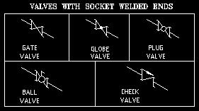
17 Valves with Weld-neck Flanges : You can draw gate, globe, plug, ball, check, wafer-check, diaphragm, and butterfly valves with this option. For check and wafer check valve, you have to select line angle through dialog box. Valves with Socket-Weld Flanges : You can draw gate, globe, plug, ball, check valves with this option. For check valve, you have to select line angle through dialog box. Valves with Lap Joint Flanges : You can draw gate, globe, plug, ball, check, wafer-check, diaphragm, and butterfly valves with this option. For check and wafer check valve, you have to select line angle through dialog box. Socket Welded Valves : You can draw gate, globe, plug, ball and check valves with this option. For check valve, you have to select line angle through dialog box.


18 Screwed Valves : You can draw gate, globe, plug, ball and check valves with this option. For check valve, you have to select line angle through dialog box. Method to Insert a Valve: First you select the option by clicking the option. Dialogue Box appears on screen showing the type of drawing PROGRAM for PIPING ISOMETRIC DRAWINGS will draw. Select the one required, by double-clicking. Click on the pipeline and in case of Gate, Globe, Plug, Ball, Diaphragm and Butterfly Valves, valve will be inserted in the line. For Check and Wafer Check valve, you pick up from dialog box the angle of pipeline in the direction of flow. The valve is drawn in the line in proper direction. You can enter valve number through a dialog box, which will be written near valve. For Hydrant valve (or PSV), double click on the end point of pipeline (osnap end is already set), pick-up from dialog box the angle of pipeline, and again pick-up from dialog box, angle of outlet of valve in the direction of flow. The Hydrant valve (or PSV) is drawn in the line. Program automatically puts these valves on layer 2, assign color of layer as cyan and also draws flanges and gaskets in the drawing. You can flip the valve if required. SPECIAL FITTINGS: When we click on this, this offers six options through icon menu. 1. Flow Transmitter with Slip-on Flanges 2. Flow Transmitter with Weld Neck Flanges 3. Control / Special Valve with Slip-on Flanges 4. Control / Special Valve with Weld Neck Flanges 5. Control / Special Valve with Socket Weld Flanges 6. Spectacle Blind When you select this option a dialogue box opens. You can select the special fitting by double clicking on the special fitting. For first 7 items, you click on pipe line. The Special Fitting is inserted in the pipe line. In case of flow transmitters and control valves, program asks for fitting name and fitting number. Program automatically puts these on layer 2 and also inserts gasket in the drawing. For spectacle blind, first click on pipe line, and


19 then pick mid point of gasket. If line is inclined a spectacle blind is inserted in vertical direction. If line is vertical, spectacle blind is inserted at 150 degrees. If angle of flange is not same, you use flip fitting option to flip valve. FITTINGS: When we click on this, this offers ten options. Single Flange : This has six options. Weld-neck, slip-on, socket-weld, lap-joint, screwed and blind flanges. You can select the option by clicking in menu. A Dialogue box appears on screen showing the type of drawing, PROGRAM for PIPING ISOMETRIC DRAWINGS will draw. Select the one required, by double-clicking, and select the pipe line (osnap nearest is already set), and from dialog box we pick the gasket side angle of pipe line. The flange is inserted in the pipe line. PROGRAM for PIPING ISOMETRIC DRAWINGS asks whether gasket is required. If you say yes, gasket is put in line near the flange, in the direction of flow. Double Flanges : This has four options, weld-neck, slip-on, socket-weld, and lap-joint. Select the option by clicking flanges. A dialogue box appears on screen showing the type of drawing PROGRAM for PIPING ISOMETRIC DRAWINGS will draw. Select the one required, by double-clicking and select the pipe line (osnap nearest is already set), and the double flanges are inserted in the pipe line. PROGRAM for PIPING ISOMETRIC DRAWINGS puts gasket in line between two flange. Branch Connection : This has nine options, equal tee, reducing tee, weldolet, threadolet, socolet, nippolet,

.")

20 stub-in, socket weld tee and screwed tee. Select the option by clicking branch connection. A Dialogue box appears on screen showing the type of drawing PROGRAM for PIPING ISOMETRIC DRAWINGS will draw. Select the one required, by double-clicking and select the pipe line. You have to then indicate the angle of side branch, through dialog box. The branch connection is inserted in the line. You can then continue drawing a pipeline. In case of reducing tee, weldolet, socolet, nipolet, threadolet and stub-in you are asked to select the size of branch pipe through dialogue box. Only valid sizes are offered for selection of reducing tees and you have to pick a point where the size is written. For stub-in, select the pipe line (osnap nearest already set). A weld is put on pipe, and you can draw the branching line. Elbows : You can draw 90 degree or 45 degree Butt Weld elbows, as arcs or as two lines. you can also draw socket weld or screwed elbows. Also, you can put a donut to indicate miter-cut. Select the option by clicking elbow. Icons appear on screen showing the type of drawing PROGRAM for PIPING ISOMETRIC DRAWINGS will draw. Select the one required, by double-clicking. For inserting an elbow, select the two pipe lines near the end (osnap end is already set). The elbow is inserted in the junction of two lines. If you are using arc option, a point will be put at the intersection of the two pipe lines, which can be picked as node during dimensioning. In case of miter cut, PROGRAM for PIPING ISOMETRIC DRAWINGS asks to select the pipe line and PROGRAM for PIPING ISOMETRIC DRAWINGS puts a weld at the end of the line. Reducer : You can draw a concentric reducer, eccentric reducer flat side up, eccentric reducer flat side down or swage. Select the option by clicking reducer. Dialogue Box appears on screen showing the type of drawing PROGRAM for PIPING ISOMETRIC DRAWINGS will draw. Select the one required, by double-clicking, and select the point on the pipe line where larger end of reducer will be inserted (osnap nearest is already set), and then a point on pipe towards the side of smaller end of reducer. You are prompted for size of pipe on other side of reducer through a dialogue box. Only valid sizes are available. You are then asked to select a point where text will be written. Program calculates offset distance and writes offset distance on reducer in case of eccentric reducers only. In all cases, PROGRAM for PIPING ISOMETRIC DRAWINGS writes size and type of reducer at the text insertion point. The reducer is inserted in the line. An alert message tells you to erase lines on other side and draw a new pipe lines with proper size. In case you select line angle as 90 degree or 270 degree for eccentric reducer, program ends action alerting that eccentric reducer can't be used in vertical lines.


21 Strainers : This offers 4 options. Y type Strainer with Slip-on Flanges or Y-Strainer with Weld Neck Flanges, Bucket type Strainer with Slip-on Flanges, or Bucket-Strainer with Weld Neck Flanges. Select the pipe line, and the strainer with flanges and gasket is drawn in the line. Couplings : You can draw full and half coupling, with butt-weld or threaded end, hexagonal coupling, victolic coupling and hose coupling. Select the option by clicking coupling. Dialogue Box appears on screen showing the type of drawing PROGRAM for PIPING ISOMETRIC DRAWINGS will draw. Select the one required, by double-clicking and then the pipe line. In first four cases, you are prompted for size of coupling through a dialogue box. You have to then select, through dialog box, the angle of side branch. PROGRAM for PIPING ISOMETRIC DRAWINGS draws coupling and you can continue drawing pipe line. PROGRAM for PIPING ISOMETRIC DRAWINGS writes size near the fitting. In case of hexagonal coupling, select the pipe line, and then size of coupling from the dialog box. The hexagonal coupling is put in the pipe line. PROGRAM for PIPING ISOMETRIC DRAWINGS writes size near the fitting. In case of victolic coupling, select the pipe line and the coupling is put in the pipe line. In case of hose coupling, you are asked for location of insertion and then angle of hose coupling, and PROGRAM for PIPING ISOMETRIC DRAWINGS draws a hose coupling. Union : With this you can draw a union. Select the option by clicking union, and then the pipe line. The union is inserted in the line. You are asked whether union is butt-welded or threaded, to draw the appropriate one. Hose : With this you can draw in-line hose which is like a bellow in a line, or flexible hose. Select the option by clicking hose. Dialogue box appears on screen showing the type of drawing PROGRAM for PIPING ISOMETRIC DRAWINGS will draw. Select the one required, by double-clicking, and then the pipe line for


22 hose and from dialog box, pick-up the angle of in-line hose, or flexible hose. The in-line hose is inserted in the pipe line and flexible hose is inserted at the point selected. Trap : With this we can draw a trap. We select the option by clicking trap and the pipeline. The trap is inserted in the line. Flip Fitting : With this we can flip any fitting in the pipeline. BILL OF MATERIAL (BOM): With this we can write BOM and edit Bill of Material. There are thirteen options: Table with Dummy Entries : Program asks for number of entries. Type in the last number of BOM list. PROGRAM for PIPING ISOMETRIC DRAWINGS then asks for pipeline size. Program draws a table with 5 more empty lines. PROGRAM for PIPING ISOMETRIC DRAWINGS writes serial numbers, line size in all rows and? entry in quantity column. PROGRAM for PIPING ISOMETRIC DRAWINGS writes desc in Description column. These are edited later, using ddedit command. Automatic Bill of Materials : PROGRAM for PIPING ISOMETRIC DRAWINGS searches for number of entities and writes in a table. Only table: You can draw a blank table. A dialog box appears, and asks for number of entries. PROGRAM for PIPING ISOMETRIC DRAWINGS draws a blank table with those many entries.


23 Edit Description : With this option you can change text in description column by selection of piping item from pull down menu. Program asks to select text to modify and then you can choose text from dialogue boxes. Text is written in place of desc. You can change or add description by editing iso10.lsp in notepad. You can edit description of Valves as per class 150# / 300# / 600# / 800# Pipes Fittings: Elbows, tee, reducer, Olets, coupling, union, plug or cap Flanges as per AS or ASME Gasket Nut Bolts When you click on the option program will ask you to select text. You can select multiple texts. A dialog box will open and allow you to select from multiple options. The selected text will be inserted in the place of text from the drawing that was selected.


24 Edit text by Class (spec) : Select proper spec from pull down menu, and then program asks to select text to modify from the BOM table. Pick up text to modify and you can replace text by typing a text or by picking corresponding one in dialog box. You can also use short commands as displayed in command prompt.


25 Stud bolt Size : You can change the size of stud bolt in BOM table in two ways, Diameter in inches and length in mm or diameter in mm and length in mm. Select the standard and class of flanges (ANSI or BS) and proper option from pull down menu. Then select the diameter of flange from dialog box and give number of sets of stud bolts. Program calculates number of bolts required for those many sets and ask to select text to replace the size and then quantity of stud bolts.
 and proper option from pull down menu. Then select the diameter of flange from dialog box and give number of sets of nut bolts.")
26 Nut bolt Size : You can change the size of Machine bolt in BOM table in two ways, Diameter in inches and length in mm or diameter in mm and length in mm. Further select the standard and class of flanges (ANSI or BS) and proper option from pull down menu. Then select the diameter of flange from dialog box and give number of sets of nut bolts. Program calculates number of bolts required for those many sets and ask to select text to replace the size and then quantity of nut bolts. Change Number By : In case there is any change in tag numbers, we can change the numbers from -5 to 5. Change Text Style to : With this we can change the style of text to either Romans or Iso3098B. Oblique Text to : With this we can oblique the text so as to fit its rotation angle. Text Height : We can change text height of the text you select to 2, 2.5 and 3 mm. Move Bill Of Material : We leave a gap of one row after valves, pipes, fittings, flanges, gaskets and stud bolts. It can be done by this option. We select text to move and PROGRAM for PIPING ISOMETRIC DRAWINGS will move it by one column down. Find and Replace : If there is any addition in tags, the number may go up. To change these numbers in tags and Bill of Material Table, we use this option. The text that will be changed is shown on screen. We change the numbers in reverse order. Erase BOM / Tags : If we use this option, all the tags and BOM Table with all entries will be erased. DIMENSIONS: Dimensions have got six options. Dimensions for Vertical Lines : With this you can write dimensions, in four inclined directions, for a vertical line. Select the option by clicking menu. Dialogue box appears on screen showing the type of dimension PROGRAM for PIPING ISOMETRIC DRAWINGS will draw. Select the one required, by double-clicking, and the two end-points, or press enter to select the line, and indicate location of dimension text, and enter dimension text. The dimension is written on the line. In case of continued dimension, select last point option at

.")

27 location of dimension. (Just press enter when asked to indicate location of dimension text). Dimensions for Inclined Lines : With this you can write dimensions, for inclined lines. Select the option by clicking menu. Dialogue box appears on screen showing the type of dimension PROGRAM for PIPING ISOMETRIC DRAWINGS will draw. Select the one required, by double-clicking, and the two end-points, or press enter to select the line, and indicate location of dimension text, and enter dimension text. The dimension is written on the line. In case of continued dimension, select last point option at location of dimension. (Just press enter when asked to indicate location of dimension text). Isodim Symbols : With this option you can draw a column reference as well as write texts as (+150), (HOLD), (REF), (TYP) below an existing dimension text. For this we pick-up option from dialogue box and then a dimension text. Text is written below the dimension text. you can also write Cl El with a line from end point of an elbow. Dim Text Height : You can change text height of all the dimensions to 1, 1.5, 2, 2.5 and 3 mm. Gasket Sign : You can put the gasket sign in dimension, using this. Pick-up end point of valve (osnap end already set), and pick-up inclination angle from dialog box. TAGS : With this you can draw spool nos., bubble, instrument tag and tag for gaskets / nut-bolts. Select the option by clicking menu. Dialogue box appears on screen showing the type of drawing PROGRAM for PIPING ISOMETRIC DRAWINGS will draw. Select the one required, by double-clicking. In case of spool no, enter the spool no as text and then pick a point where text should appear. Then select pipeline or fitting (osnap nearest is already set), and then select second point on spool tag to draw a line indicating the spool. In case of bubble, select pipeline or fitting (osnap nearest is already set), and then select second point where
, and then select second point where the tag no will be written. Fill in dialog box text for fitting type and number.")


28 the tag no will be written. A tag no is displayed. You can accept the same number by pressing enter or type a new number and press enter. In case of instrument no., select instrument valve, or fitting (osnap nearest is already set), and then select second point where the tag no will be written. Fill in dialog box text for fitting type and number. Fitting tag appears. In case of circle, select the earlier circle at the top point (osnap nearest is already set), A tag no will be displayed. You can accept same number by pressing enter or type a new number. HATCH: With this you can draw vertical or horizontal hatch patterns in 5 different ways by selecting three pipe lines. In first 2 cases you can do horizontal hatching in 2 different ways. With third you can do vertical hatching. When you select a pipe line, program asks for dimension of this pipe line. Hatch repears for other two pipe lines. hatch then runs zoom window command and ask you to select window to zoom the area where to write angle. After you write angle, drawing will zoom to previous view. With fourth and fifth option, you can draw vertical or horizontal hatch patterns by selecting three pipe lines. After you select each pipe line, program asks for the length to be written as text. After hatch is drawn, program writes length of the three lines. Program then runs zoom window command and ask to select window to zoom the area where to write angle. After you write angle, program will zoom to previous view. WELD: With this you can draw welds or ends. Six options are available. Butt-weld included in this drawing option will draw filled donut, Butt-weld not included in this drawing option will draw hollow circle. Other options will draw socket-weld end, screwed end, field weld, field fit weld. Select the option by clicking weld option. Dialogue Box appears on screen showing the type of welds / ends program will draw. Select the one required, by double-clicking. Then select pipeline (osnap nearest is already set), where a weld or end is drawn instantly. DATA: Program gives data of following items. Pipe : Pipe OD and Half OD in mm. Fittings : Length of following fittings long radius Elbow short radius Elbow Elbow 4. Equal Tee 5. Reducing Tee 6. Reducer 7. Weldolet
29 8. Cap Flanges : Weights, lengths, diameters of Slip on/weld Neck flanges for ANSI 150, 300, 600, 900, 1500 and 2500 # flanges. We select Flange diameter and we get all the information. Stud Bolt : Numbers, lengths, diameters of stud bolts for Slip on/weld Neck flanges for ANSI 150, 300, 600, 900, 1500 and 2500 # flanges. We select Flange diameter and we get all the information. Valves : Flange to flange distance for gate, globe and check valves of 150, 300 and 600#. We select Flange diameter and we get all the information. Distances : 1. Minimum pipe between Elbow and reducer. 2. Between End of Reducer to center of tee. 3. Between End of Reducer to center of 90 degree Elbow. 4. Between center of tee to center of tee. 5. Between center of tee to center of 90 degree Elbow. 6. Between center of 90 degree Elbow to center of 90 degree Elbow. 7. Between center of 90 degree Elbow to center of 45 degree Elbow. 8. Between center of 45 degree Elbow to center of 45 degree Elbow. Check List for Isometric Drawings 1. Check whether P&ID number and GA drawing number is correct. 2. Check Line Number in Title Block. 3. Check whether direction of flow and other details are as per P&ID. 4. Check details of vents and drains, dimensions of vent from high point / drain from BOP or low point. 5. Field weld should be provided for every 12 meters of pipe line. 6. If some exact dimension is not known, like FOF of pump or length of valve, provide a field fit weld. Add 150 mm to the length of pipe line in BOM table and indicate (+150) below tag of dimension. 7. If straight length of pipe exceeds 4 meters, provide a field fit weld and indicate (+150) below tag of dimension. 8. Check sizes of all fittings as per standard. Check proper symbols for gate, globe and check valves. 9. Provide tag numbers to every cut pipe and all fittings. Different types of fittings should have different numbers. These tag numbers should match with those in BOM table. Lengths of pipes should be exact cut lengths. 10. Spool numbers to be given to all spools. The number is same as drawing number with A,B,C,D etc. added to spool. 11. For instruments, show piping scope and instrument scope. For FE, show tappings in proper directions, size, length and detail. Show spec change, if any. Size for TG should be 200 mm and for PI should be 40 mm. 12. If line is continuing in other drawing, (C.O.D.), indicate iso number of that pipe line, or write
30 field run for small pipe lines. 13. Reference elevation should be indicated at least at one point. 14. Proper symbol for butt weld, socket weld and screwed connection. 15. If an iso has more than one line, the number of main line should be written in title block, and numbers of other lines under This Drawing Includes: 16. Match line for split drawings and dotted lines for pipe lines from other drawings. 17. Hatching for angular details, horizontal hatch for horizontal turn and vertical hatch for verticle turn. Indicate angle of turn. Dimensions should be provided for three sides. CL EL for three lines. 18. Special fittings should be marked properly with a tag number and tag should reflect in BOM table. 19. Tag number of valve should be written below the valve and should reflect in BOM table. 20. Check fittings as per spec and branching table. 21. Indicate sign of gasket for valves in dimension. 22. Indicate nozzle number for equipments. 23. If mating flange of a pump is supplied by pump vendor, indicate it on drawing. 24. If an end of pipe line is open, indicate open end on drawing. 25. Show spec break, if any. 26. Show cloud for hold. 27. Show insulation for insulated pipe lines. 28. Show special specs like rubber lined or SS, 3D bends or part insulation. 29. For reducing tee and reducers, indicate size and type as per spec and branching table. 30. For olets, indicate NB of branch. 31. Check obliquing angle for all texts and dimensions. 32. Provide weld numbers in direction of flow. 33. In BOM table, entities should be in order. Pipes, Valves, Fittings, Gaskets and Stud bolts. A line should be left blank between these groups. 34. Check cross-referenced drawings and check details in title block. Some samples of drawings

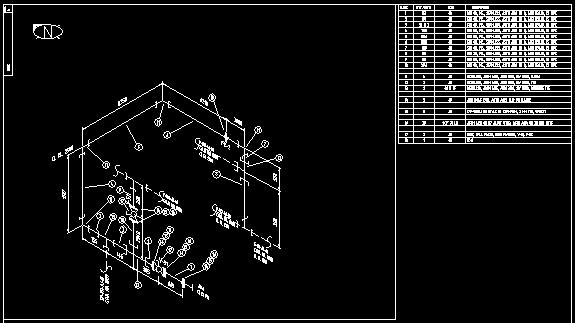
31 Isometric Drawing drawn by our AutoLISP Program. Isometric Drawing drawn by our AutoLISP Program.

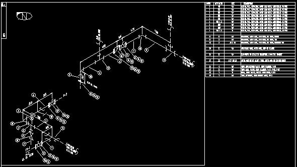
32 Isometric Drawing drawn by our AutoLISP Program. Isometric Drawing drawn by our AutoLISP Program.


33 Part of Isometric Drawing showing Bill of Material for Socket Weld Fittings Drawn by our AutoLISP Program. Part of Isometric Drawing showing Bill of Material for Butt Weld Fittings Drawn by our AutoLISP Program.

34 Isometric Drawing showing a Detail drawn by our AutoLISP Program.
CADPIPE Industrial Pipe. Tutorial
 CADPIPE Industrial Pipe Tutorial Introduction This Tutorial is a brief introduction to the power of CADPIPE 3D DESIGN. We will show you a few key features and the general procedures for creating 3D piping
Chapter 8. Piping Isometrics
 Chapter 8 Piping Isometrics An isometric drawing is a type of pictorial drawing in which three sides of an object can be seen in one view. It s popular within the process piping industry because it can
Block References and Attributes
 CHAPTER 11 Block References and Attributes PROJECT EXERCISE 11A This project exercise provides point-by-point instructions for creating the objects shown in Figure P11A 1. In this exercise, you will apply
DETAILED ENGINEERING OF PROCESS PIPING SYSTEMS
 LAST UPDATED 25-10-2017 DETAILED ENGINEERING OF PROCESS PIPING SYSTEMS COURSE DURATION: 5 DAYS REACH US Today for Greater Safety, Quality, Reliability, Productivity, Profitability HRD Approved Class A
Working with Process Flow DiagramsChapter1:
 Chapter 1 Working with Process Flow DiagramsChapter1: In this chapter, you learn about designing piping with AutoCAD MEP. The design phase consists of conceptualizing, modeling, and documenting the necessary
Ball Valve Assembly. On completion of the assembly, we will create the exploded view as shown on the right.
 Ball Valve Assembly Supplied are the main components of a ball valve. In this exercise you will assemble the valve as shown below Left. (N.B. Socket head cap screws are not supplied these will be created
Engineering Design & Power Training Institute
 Engineering Design & Power Training Institute Recognition & Approvals Association of Power & Design Engineers (APDE) An ISO 9001: 2008 Certified Institute Courses P G Diploma in Piping Design & Details
Advance Steel. Tutorial
 Advance Steel Tutorial Table of contents About this tutorial... 7 How to use this guide...9 Lesson 1: Creating a building grid...10 Step 1: Creating an axis group in the X direction...10 Step 2: Creating
Principles and Practice
 Principles and Practice An Integrated Approach to Engineering Graphics and AutoCAD 2011 Randy H. Shih Oregon Institute of Technology SDC PUBLICATIONS www.sdcpublications.com Schroff Development Corporation
Isometric Drawings. Figure A 1
 A Isometric Drawings ISOMETRIC BASICS Isometric drawings are a means of drawing an object in picture form for better clarifying the object s appearance. These types of drawings resemble a picture of an
Stepping ahead in technology & innovation PIPING INSTITUTE OF TECHNOLOGY & ANALYSIS SOLUTIONS
 Stepping ahead in technology & innovation PIPING INSTITUTE OF TECHNOLOGY & ANALYSIS SOLUTIONS PIPING ENGINEERING & PLANT DESIGN Chapter 1. Introduction of Piping Industry & Role of Piping Engineer 1.1.
Technical Drawing 101 with AutoCAD 2018
 Technical Drawing 101 with AutoCAD 2018 A Multidisciplinary Guide to Drafting Theory and Practice with Video Instruction Douglas Smith Antonio Ramirez Ashleigh Fuller SDC PUBLICATIONS Better Textbooks.
Dimensioning the Rectangular Problem
 C h a p t e r 3 Dimensioning the Rectangular Problem In this chapter, you will learn the following to World Class standards: 1. Creating new layers in an AutoCAD drawing 2. Placing Centerlines on the drawing
Engineering Technology
 Engineering Technology Introduction to Parametric Modelling Engineering Technology 1 See Saw Exercise Part 1 Base Commands used New Part This lesson includes Sketching, Extruded Boss/Base, Hole Wizard,
Project Booklet. Structural Drafting with AutoCAD
 Project Booklet Structural Drafting with AutoCAD Introduction 1 General Setup 2 Border and Title Block 3 Drafting the Foundation Plan (Plate 1) 8 Drafting the South Elevation (Plate 2) 11 Drafting Section
Chapter 6 Title Blocks
 Chapter 6 Title Blocks In previous exercises, every drawing started by creating a number of layers. This is time consuming and unnecessary. In this exercise, we will start a drawing by defining layers
Completed project drawing (dimensions added for reference)
") CHAPTER 5 Fundamentals IV PROJECT EXERCISE This project exercise provides point-by-point instructions for setting up the drawing with layers and then creating the objects shown in the accompanying figure.
CHAPTER 5 Fundamentals IV PROJECT EXERCISE This project exercise provides point-by-point instructions for setting up the drawing with layers and then creating the objects shown in the accompanying figure.
AutoCAD 2D I. Module 16. Isometric and Dimensioning. IAT Curriculum Unit PREPARED BY. January 2011
 AutoCAD 2D I Module 16 Isometric and Dimensioning PREPARED BY IAT Curriculum Unit January 2011 Institute of Applied Technology, 2011 Module 16 Auto CAD Self-paced Learning Modules AutoCAD 2D Isometric
Anchor Block Draft Tutorial
 Anchor Block Draft Tutorial In the following tutorial you will create a drawing of the anchor block shown. The tutorial covers such topics as creating: Orthographic views Section views Auxiliary views
Engineering & Computer Graphics Workbook Using SolidWorks 2014
 Engineering & Computer Graphics Workbook Using SolidWorks 2014 Ronald E. Barr Thomas J. Krueger Davor Juricic SDC PUBLICATIONS Better Textbooks. Lower Prices. www.sdcpublications.com Powered by TCPDF (www.tcpdf.org)
GEN20604 Intelligent AutoCAD Model Documentation Made Easy
 GEN20604 Intelligent AutoCAD Model Documentation Made Easy David Cohn 4D Technologies Learning Objectives Learn how to create base views and projected views from 3D models Learn how to create and control
Engineering & Computer Graphics Workbook Using SOLIDWORKS
 Engineering & Computer Graphics Workbook Using SOLIDWORKS 2017 Ronald E. Barr Thomas J. Krueger Davor Juricic SDC PUBLICATIONS Better Textbooks. Lower Prices. www.sdcpublications.com Powered by TCPDF (www.tcpdf.org)
Solid Part Four A Bracket Made by Mirroring
 C h a p t e r 5 Solid Part Four A Bracket Made by Mirroring This chapter will cover the following to World Class standards: Sketch of a Solid Problem Draw a Series of Lines Finish the 2D Sketch Extrude
Autodesk Architectural Desktop Functionality for the Autodesk Building Systems User
 11/28/2005-1:00 pm - 2:30 pm Room:N. Hemispheres (Salon A1) (Dolphin) Walt Disney World Swan and Dolphin Resort Orlando, Florida Autodesk Architectural Desktop Functionality for the Autodesk Building Systems
Outfitting Detail Design suite
 Outfitting Detail Design suite 2015Q3 The Cadmatic 3D Outfitting Detail Design suite is an integrated, databasedriven design module and provides powerful tools for 3D layout-, piping-, HVAC-, cable tray-
Shaft Hanger - SolidWorks
 ME-430 INTRODUCTION TO COMPUTER AIDED DESIGN Shaft Hanger - SolidWorks BY: DR. HERLI SURJANHATA ASSIGNMENT Submit TWO isometric views of the Shaft Hanger with your report, 1. Shaded view of the trimetric
Chapter 5 Sectional Views
 Chapter 5 Sectional Views There are a number of different types of sectional views that can be drawn. A few of the more common ones are: full sections, half sections, broken sections, rotated or revolved
User Guide V10 SP1 Addendum
 Alibre Design User Guide V10 SP1 Addendum Copyrights Information in this document is subject to change without notice. The software described in this document is furnished under a license agreement or
COURSE: INTRODUCTION TO CAD GRADES: UNIT: Measurement
 UNIT: Measurement - Students will demonstrate correctness in measuring using various scales and instruments. Demonstrate the various marks that make up a ruler including 1/16, 1/8, ¼ and ½. Assessment
LABORATORY MANUAL COMPUTER AIDED DRAFTING LAB ME-211-E
 LABORATORY MANUAL COMPUTER AIDED DRAFTING LAB ME-211-E 1 LIST OF EXPERIMENTS COMPUTER AIDED DRAFTING M E-211-E S. No. NAME OF EXPERIMENTS 1. To Implement Simple programs for the graphics representation
AutoCAD LT 2012 Tutorial. Randy H. Shih Oregon Institute of Technology SDC PUBLICATIONS. Schroff Development Corporation
 AutoCAD LT 2012 Tutorial Randy H. Shih Oregon Institute of Technology SDC PUBLICATIONS www.sdcpublications.com Schroff Development Corporation AutoCAD LT 2012 Tutorial 1-1 Lesson 1 Geometric Construction
DRAFT Solid Edge ST4 Update Training Draft
 DRAFT Solid Edge ST4 Update Training Draft Presented by: Steve Webb Topics Parts List Table Titles Column Headers Headers Merging Header Rotate Cell Aspect Ratio Cell Formatting Overriding Disabled Cells
Assignment 12 CAD Mechanical Part 2
 Assignment 12 CAD Mechanical Part 2 Objectives In this assignment you will learn to apply the hidden lines, isometric snap, and ellipses commands along with commands previously learned.. General Hidden
Tenviewing a Solid. In this chapter, we will learn the following to World Class standards:
 C h a p t e r 15 Tenviewing a Solid In this chapter, we will learn the following to World Class standards: Converting 3D Solids to 2D Orthographic Views Opening the Solid Part Drawing Loading Tenview.LSP
Copyrighted Material. Copyrighted Material. Copyrighted. Copyrighted. Material
 Engineering Graphics ORTHOGRAPHIC PROJECTION People who work with drawings develop the ability to look at lines on paper or on a computer screen and "see" the shapes of the objects the lines represent.
Principles and Practice:
 Principles and Practice: An Integrated Approach to Engineering Graphics and AutoCAD 2014 Randy H. Shih Multimedia Disc SDC PUBLICATIONS Better Textbooks. Lower Prices. www.sdcpublications.com Video presentations
Engineering Working Drawings Basics
 Engineering Working Drawings Basics Engineering graphics is an effective way of communicating technical ideas and it is an essential tool in engineering design where most of the design process is graphically
AutoCAD Tutorial First Level. 2D Fundamentals. Randy H. Shih SDC. Better Textbooks. Lower Prices.
 AutoCAD 2018 Tutorial First Level 2D Fundamentals Randy H. Shih SDC PUBLICATIONS Better Textbooks. Lower Prices. www.sdcpublications.com Powered by TCPDF (www.tcpdf.org) Visit the following websites to
Autodesk Advance Steel. Drawing Style Manager s guide
 Autodesk Advance Steel Drawing Style Manager s guide TABLE OF CONTENTS Chapter 1 Introduction... 5 Details and Detail Views... 6 Drawing Styles... 6 Drawing Style Manager... 8 Accessing the Drawing Style
Sheet Metal OverviewChapter1:
 Sheet Metal OverviewChapter1: Chapter 1 This chapter describes the terminology, design methods, and fundamental tools used in the design of sheet metal parts. Building upon these foundational elements
Principles and Practice
 Principles and Practice An Integrated Approach to Engineering Graphics and AutoCAD 2016 Randy H. Shih SDC PUBLICATIONS Better Textbooks. Lower Prices. www.sdcpublications.com Powered by TCPDF (www.tcpdf.org)
ENGINEERING GRAPHICS ESSENTIALS
 ENGINEERING GRAPHICS ESSENTIALS with AutoCAD 2012 Instruction Introduction to AutoCAD Engineering Graphics Principles Hand Sketching Text and Independent Learning CD Independent Learning CD: A Comprehensive
Revit Structure 2012 Basics:
 SUPPLEMENTAL FILES ON CD Revit Structure 2012 Basics: Framing and Documentation Elise Moss autodesk authorized publisher SDC PUBLICATIONS www.sdcpublications.com Schroff Development Corporation Structural
This specification describes the minimum technical requirements for drawings, as applicable to all disciplines.
 SPEC-0800 1/5 1.0 PURPOSE This specification describes the minimum technical requirements for drawings, as applicable to all disciplines. 2.0 VALE DRAWING TYPE DEFINITIONS Engineering Drawings Engineering
with MultiMedia CD Randy H. Shih Jack Zecher SDC PUBLICATIONS Schroff Development Corporation
 with MultiMedia CD Randy H. Shih Jack Zecher SDC PUBLICATIONS Schroff Development Corporation WWW.SCHROFF.COM Lesson 1 Geometric Construction Basics AutoCAD LT 2002 Tutorial 1-1 1-2 AutoCAD LT 2002 Tutorial
Advance Steel. Drawing Style Manager s guide
 Advance Steel Drawing Style Manager s guide TABLE OF CONTENTS Chapter 1 Introduction...7 Details and Detail Views...8 Drawing Styles...8 Drawing Style Manager...9 Accessing the Drawing Style Manager...9
SDC. AutoCAD LT 2007 Tutorial. Randy H. Shih. Schroff Development Corporation Oregon Institute of Technology
 AutoCAD LT 2007 Tutorial Randy H. Shih Oregon Institute of Technology SDC PUBLICATIONS Schroff Development Corporation www.schroff.com www.schroff-europe.com AutoCAD LT 2007 Tutorial 1-1 Lesson 1 Geometric
Appendix B: Autocad Booklet YR 9 REFERENCE BOOKLET ORTHOGRAPHIC PROJECTION
 Appendix B: Autocad Booklet YR 9 REFERENCE BOOKLET ORTHOGRAPHIC PROJECTION To load Autocad: AUTOCAD 2000 S DRAWING SCREEN Click the start button Click on Programs Click on technology Click Autocad 2000
Module 1G: Creating a Circle-Based Cylindrical Sheet-metal Lateral Piece with an Overlaying Lateral Edge Seam And Dove-Tail Seams on the Top Edge
 Inventor (10) Module 1G: 1G- 1 Module 1G: Creating a Circle-Based Cylindrical Sheet-metal Lateral Piece with an Overlaying Lateral Edge Seam And Dove-Tail Seams on the Top Edge In Module 1A, we have explored
Isometrics COMOS. Process Isometrics. Trademarks 1. Introduction 2. Project structure 3. Isometric report 4. Engineering with COMOS Isometrics
 Trademarks 1 Introduction 2 COMOS Process Operating Manual Project structure 3 Isometric report 4 Engineering with COMOS 5 Creating an isometric drawing from existing 3D data 6 IDF import 7 Administration
SOLIDWORKS 2015 and Engineering Graphics
 SOLIDWORKS 2015 and Engineering Graphics An Integrated Approach Randy H. Shih SDC PUBLICATIONS Better Textbooks. Lower Prices. www.sdcpublications.com Powered by TCPDF (www.tcpdf.org) Visit the following
SolidWorks 95 User s Guide
 SolidWorks 95 User s Guide Disclaimer: The following User Guide was extracted from SolidWorks 95 Help files and was not originally distributed in this format. All content 1995, SolidWorks Corporation Contents
GstarCAD Mechanical 2015 Help
 1 Chapter 1 GstarCAD Mechanical 2015 Introduction Abstract GstarCAD Mechanical 2015 drafting/design software, covers all fields of mechanical design. It supplies the latest standard parts library, symbols
Lesson 6 2D Sketch Panel Tools
 Lesson 6 2D Sketch Panel Tools Inventor s Sketch Tool Bar contains tools for creating the basic geometry to create features and parts. On the surface, the Geometry tools look fairly standard: line, circle,
ME Week 2 Project 2 Flange Manifold Part
 1 Project 2 - Flange Manifold Part 1.1 Instructions This project focuses on additional sketching methods and sketching commands. Revolve and Work features are also introduced. The part being modeled is
8 Working Drawings in AutoCAD
 8 Working Drawings in AutoCAD Most engineering designs consist of more than a single part. Usually there are a several or many parts that must fit and work together. When we are creating the drawings of
Learning Guide. ASR Automated Systems Research Inc. # Douglas Crescent, Langley, BC. V3A 4B6. Fax:
 Learning Guide ASR Automated Systems Research Inc. #1 20461 Douglas Crescent, Langley, BC. V3A 4B6 Toll free: 1-800-818-2051 e-mail: support@asrsoft.com Fax: 604-539-1334 www.asrsoft.com Copyright 1991-2013
EC-CAD New features and changes The following improvements have been made to the EC-CAD Product: EC Design to Fabrication.
 RELEASE NOTES EC Design to Fabrication This document contains summary information on new features, late-breaking product information, updates, and troubleshooting tips not covered in the Trimble EC Design
Certified SOLIDWORKS Professional Advanced Preparation Materials
 Includes Preparation for Five Advanced Certification Exams Certified SOLIDWORKS Professional Advanced Preparation Materials Sheet Metal, Weldments, Surfacing, Mold Tools and Drawing Tools SOLIDWORKS 2016
and Engineering Graphics
 SOLIDWORKS 2018 and Engineering Graphics An Integrated Approach Randy H. Shih SDC PUBLICATIONS Better Textbooks. Lower Prices. www.sdcpublications.com Powered by TCPDF (www.tcpdf.org) Visit the following
An Introduction to Autodesk Inventor 2011 and AutoCAD Randy H. Shih SDC PUBLICATIONS. Schroff Development Corporation
 An Introduction to Autodesk Inventor 2011 and AutoCAD 2011 Randy H. Shih SDC PUBLICATIONS www.sdcpublications.com Schroff Development Corporation An Introduction to Autodesk Inventor 2011 and AutoCAD 2011
1: INTRODUCTION TO AUTOCAD
 AutoCAD syllabus 1: INTRODUCTION TO AUTOCAD Starting AutoCAD AutoCAD Screen Components Drawing Area Command Window Navigation bar Status bar Invoking Commands in AutoCAD Keyboard Ribbon Application Menu
Designing in the context of an assembly
 SIEMENS Designing in the context of an assembly spse01670 Proprietary and restricted rights notice This software and related documentation are proprietary to Siemens Product Lifecycle Management Software
Working With Drawing Views-I
 Chapter 12 Working With Drawing Views-I Learning Objectives After completing this chapter you will be able to: Generate standard three views. Generate Named Views. Generate Relative Views. Generate Predefined
06/17/02 Page 1 of 12
 Understanding the Graphical User Interface When you start AutoCAD, the AutoCAD window opens. The window is your design work space. It contains elements that you use to create your designs and to receive
Copyrighted. Material. Copyrighted. Material. Copyrighted. Copyrighted. Material
 Engineering Graphics FREEHAND SKETCHING Introduction to Freehand Sketching Sketching is a very important technique for technical communication. Sketches can transfer ideas, instructions and information
Making an Architectural Drawing Template
 C h a p t e r 8 Addendum: Architectural Making an Architectural Drawing Template In this chapter, you will learn the following to World Class standards:! Starting from Scratch for the Last time! Creating
Getting Started Guide
 SOLIDWORKS Getting Started Guide SOLIDWORKS Electrical FIRST Robotics Edition Alexander Ouellet 1/2/2015 Table of Contents INTRODUCTION... 1 What is SOLIDWORKS Electrical?... Error! Bookmark not defined.
The Revolve Feature and Assembly Modeling
 The Revolve Feature and Assembly Modeling PTC Clock Page 52 PTC Contents Introduction... 54 The Revolve Feature... 55 Creating a revolved feature...57 Creating face details... 58 Using Text... 61 Assembling
1Getting set up to start this exercise
 AutoCAD Architectural DesktopTM 2.0 - Development Guide EXERCISE 1 Creating a Foundation Plan and getting an overview of how this program functions. Contents: Getting set up to start this exercise ----
TUTORIAL 4: Combined Axial and Bending Problem Sketch Path Sweep Initial Project Space Setup Static Structural ANSYS
 TUTORIAL 4: Combined Axial and Bending Problem In this tutorial you will learn how to draw a bar that has bends along its length and therefore will have both axial and bending stresses acting on cross-sections
This specification describes the minimum requirements for piping systems for the following service:
 201/11/2 1/9 1.0 APPLICATION This specification describes the minimum requirements for piping systems for the following service: Underground Service Water Note: This specification does not apply to piping
This specification describes the minimum requirements for piping systems for the following service:
 201/01/13 1/ 1.0 APPLICATION This specification describes the minimum requirements for piping systems for the following service: Service Air Design Conditions Operating Conditions Blast Air (see Note 1)
Product Modelling in Solid Works
 Product Modelling in Solid Works In the following exercise you will use solid works to construct the computer mouse shown opposite. In this exercise you will use a number of advanced features to achieve
Autodesk. AutoCAD Architecture Fundamentals. Elise Moss SDC PUBLICATIONS. Schroff Development Corporation
 Autodesk AutoCAD Architecture 2008 Fundamentals Elise Moss SDC PUBLICATIONS Schroff Development Corporation www.schroff.com www.schroff-europe.com Lesson 3 Floor Plans The floor plan is central to any
AutoCAD LT 2009 Tutorial
 AutoCAD LT 2009 Tutorial Randy H. Shih Oregon Institute of Technology SDC PUBLICATIONS Schroff Development Corporation www.schroff.com Better Textbooks. Lower Prices. AutoCAD LT 2009 Tutorial 1-1 Lesson
Creating a 2D Drawing in Paper Space
 C h a p t e r 16 Creating a 2D Drawing in Paper Space In this chapter, we will learn the following to World Class standards: 1. Converting 3D Solids to 2D Orthographic Views 2. Open the Solid Part Drawing
LABORATORY MANUAL COMPUTER AIDED DESIGN LAB ME-211-F
 LABORATORY MANUAL COMPUTER AIDED DESIGN LAB ME-211-F List of Experiments:- Sl. No. Name of experiment Date Signature 01 02 Setting up of drawing environment by setting drawing limits, drawing units, naming
Introduction to Sheet Metal Features SolidWorks 2009
 SolidWorks 2009 Table of Contents Introduction to Sheet Metal Features Base Flange Method Magazine File.. 3 Envelopment & Development of Surfaces.. 14 Development of Transition Pieces.. 23 Conversion to
Toothbrush Holder. A drawing of the sheet metal part will also be created.
 Prerequisite Knowledge Previous knowledge of the following commands is required to complete this lesson; Sketch (Line, Centerline, Circle, Add Relations, Smart Dimension,), Extrude Boss/Base, and Edit
Tools for Design. with VEX Robot Kit: Randy H. Shih Oregon Institute of Technology SDC PUBLICATIONS
 Tools for Design with VEX Robot Kit: AutoCAD 2011 and Autodesk Inventor 2011 2D Drawing 3D Modeling Hand Sketching Randy H. Shih Oregon Institute of Technology INSIDE: SUPPLEMENTAL FILES ON CD SDC PUBLICATIONS
UNIT 5a STANDARD ORTHOGRAPHIC VIEW DRAWINGS
 UNIT 5a STANDARD ORTHOGRAPHIC VIEW DRAWINGS 5.1 Introduction Orthographic views are 2D images of a 3D object obtained by viewing it from different orthogonal directions. Six principal views are possible
HVAC in AutoCAD MEP: New and Improved. David Butts Gannett Fleming MP3724-L. Learning Objectives. At the end of this class, you will be able to:
 David Butts Gannett Fleming MP3724-L In the Building Information Modeling (BIM) world, there are still many users who have AutoCAD MEP but aren't ready to make the move to Autodesk Revit for a variety
Modeling an Airframe Tutorial
 EAA SOLIDWORKS University p 1/11 Difficulty: Intermediate Time: 1 hour As an Intermediate Tutorial, it is assumed that you have completed the Quick Start Tutorial and know how to sketch in 2D and 3D. If
This specification describes the minimum requirements for service water piping systems (ie: cooling water, process water, etc.), located on surface.
, located on surface.") SPEC-3500 1/9 1.0 PURPOSE This specification describes the minimum requirements for service water piping systems (ie: cooling water, process water, etc.), located on surface. Note: This specification does
SPEC-3500 1/9 1.0 PURPOSE This specification describes the minimum requirements for service water piping systems (ie: cooling water, process water, etc.), located on surface. Note: This specification does
Unit. Drawing Accurately OVERVIEW OBJECTIVES INTRODUCTION 8-1
 8-1 Unit 8 Drawing Accurately OVERVIEW When you attempt to pick points on the screen, you may have difficulty locating an exact position without some type of help. Typing the point coordinates is one method.
Revit Structure 2013 Basics
 Revit Structure 2013 Basics Framing and Documentation Elise Moss Supplemental Files SDC P U B L I C AT I O N S Schroff Development Corporation Better Textbooks. Lower Prices. www.sdcpublications.com Tutorial
This specification describes the minimum requirements for piping systems for the following service:
 SPEC-3004 1/7 1.0 APPLICATION This specification describes the minimum requirements for piping systems for the following service: Service Water Design Conditions Operating Conditions 10 PSIG @ 33 o F to
Dharmapuri LAB MANUAL. : B.E. - Civil Engineering Year & Semester : I Year / II Semester
 Dharmapuri 636 703 LAB MANUAL Regulation : 2013 Branch : B.E. - Civil Engineering Year & Semester : I Year / II Semester CE6261-COMPUTER AIDED DRAFTING AND MODELLING LABORATORY ICAL ENG VVIT DEPARTMENT
Template Drawings. Template Drawings. AutoCAD Essentials
 AutoCAD Essentials Starting a new drawing using any CAD software requires a series of steps. Measurement units, sheet size, layer designations, text fonts and text sizes plus many more items must be set.
CAD Drafting Standards
 Marine Institute of Memorial University of Newfoundland CAD Drafting Standards Marine Engineering Systems Design Department Revision 1 List of Revisions Revision Description Date 0 INITIAL ISSUE Sep/16/2009
Sheet metal tutorial. To set the bend radius Right click on the first sheet metal icon in the command manager and specify a bend radius or 1mm.
 Sheet metal tutorial In the following tutorial you will cover the basic features of the Solid Works sheet metal tool by modelling the component shown opposite. Activating Sheet metal mode Sheet metal components
Sheet Metal OverviewChapter1:
 Sheet Metal OverviewChapter1: Chapter 1 This chapter describes the terminology, design methods, and fundamental tools used in the design of sheet metal parts. Building upon these foundational elements
EDUCATIONAL REND LAKE COLLEGE CAD INTRODUCTION TO COMPUTER-AIDED DRAFTING ISOMETRIC DRAWING REVISED: FALL 2010 INSTRUCTOR: THOMAS ARPASI
 INSTRUCTOR: THOMAS ARPASI REND LAKE COLLEGE CAD 1201-51 INTRODUCTION TO COMPUTER-AIDED DRAFTING ISOMETRIC DRAWING 1 Pictoral Drawing Pictoral drawing have evolved from cave paintings to photorealistic
Starting a New Drawing with a Title Block and Border
 Starting a New Drawing with a Title Block and Border From the File menu select New. Within the New file menu toggle the option Drawing, name the file and turn Off the toggle Use Default Template. Select
Module 2: Radial-Line Sheet-Metal 3D Modeling and 2D Pattern Development: Right Cone (Regular, Frustum, and Truncated)
") Inventor (5) Module 2: 2-1 Module 2: Radial-Line Sheet-Metal 3D Modeling and 2D Pattern Development: Right Cone (Regular, Frustum, and Truncated) In this tutorial, we will learn how to build a 3D model
Inventor (5) Module 2: 2-1 Module 2: Radial-Line Sheet-Metal 3D Modeling and 2D Pattern Development: Right Cone (Regular, Frustum, and Truncated) In this tutorial, we will learn how to build a 3D model
Arranging and Patterning Objects
 C H A P T E R Arranging and Patterning Objects Learning Objectives After completing this chapter, you will be able to do the following: Relocate objects using the MOVE tool. Change the angular positions
Module 1H: Creating an Ellipse-Based Cylindrical Sheet-metal Lateral Piece
 Inventor (10) Module 1H: 1H- 1 Module 1H: Creating an Ellipse-Based Cylindrical Sheet-metal Lateral Piece In this Module, we will learn how to create an ellipse-based cylindrical sheetmetal lateral piece
IDEA Connections. User guide
 IDEA Connections user guide IDEA Connections User guide IDEA Connections user guide Content 1.1 Program requirements... 4 1.1 Installation guidelines... 4 2 User interface... 5 2.1 3D view in the main