Vortex TRAUMATOLOGY. Vortex Distal Femur
|
|
|
- Sabina Allison
- 5 years ago
- Views:
Transcription

1 Vortex TRAUMATOLOGY Vortex Distal Femur 1
2 Content 1. Introduction 4 4. Implant list The following surgical description contains general outlines for Vortex Distal Femur plating. However, the operating surgeon shall adapt the content to the patient, fracture The implant The instruments Indications Instrument list 18 type and all other relevant factors that may have influence on the outcome of the surgery. 2. Implant range 5 3. Surgical description 6-9 Therefore, Sanatmetal Ltd. strongly recommends participation on workshops and 3.1 Patient positioning 6 trainings prior to the initial operation. 3.2 Plate selection Assembly of plate and targeting arm Incision Modellation of the plate Insertion of the plate Positioning with the oval hole Closing the frame Temporary fixation of the plate Fixation of the head Planned direction locking Assembly of the head block Planned direction drilling head Length gauging head Screw insertion head Drilling tail Length gauging tail Screw insertion tail Selected direction locking Selected direction drilling head Length gauging head Screw insertion head Drilling tail Length gauging tail Screw insertion tail 15

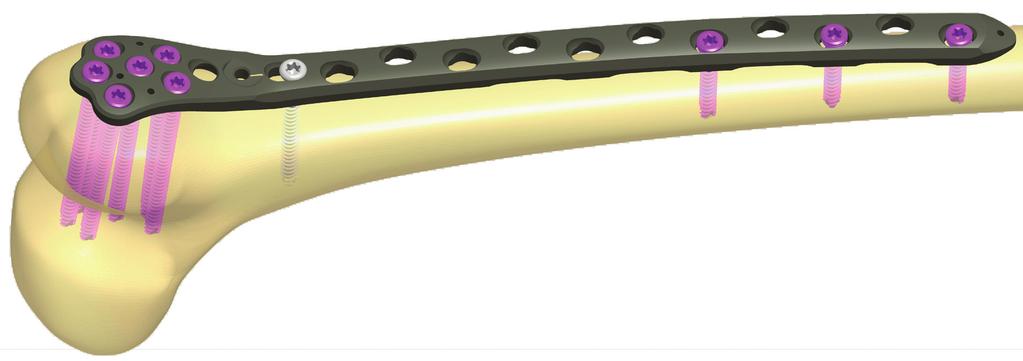
3 1 Introduction Implant range 2 Vortex plates, serving to heal peri- and intraarticular fractures, have a new family member, VDF (Vortex Distal Femur) which goes to the distal part of the femur bone offering the same usual high end features that we got used to from Vortex plates. The comfort and security of polyaxial locking is further enhanced by a minimally invasive radiolucent targeting arm for the tail. To reach stabile-enough locking the system uses dia 5,1 mm polyaxial and cortical screws. They represent the outstanding features of Vortex screws together with excellent mechanical properties. 1.1 The implant 1.2 The instruments Polyaxial angle stabilized system in step - free ±15 deg angulation of insertion Optimal, pre-determined screw directions in the holes Maximum 3 times of correction possibility when misidentifying the correct screw direction Thinned head, the implant does not interfere with the soft tissues Rounded edges to protect nearby soft tissues Oval hole for plate positioning Ability to perform minimally invasive surgery Self tapping but blunt ended screws to avoid tissue irritation Capable of drilling in preset and ±15 deg directions step free Easy to assemble targeting head for choosing either selected or planned direction fixation in the pre-determined directions. Radio translucent targeting arm for the tail holes Instruments and implants in one tray Optimized instruments coded torque limiting screwdriver 1.3 Indications Distal femoral fractures Periprosthetic fractures 2.1 Vortex Distal Femur plate 2.2 Vortex screw Ø5,1 mm Holes on tail Side 6H right/left 8H right/left Length (mm) 10H right/left H right/left 14H right/left 16H right/left purple grey 2.3 Vortex screw Ø5,1 mm 2.4 Cortical screw - TX Ø5,1 mm Length (mm) Length (mm) purple grey raw material Torx recess screws 2.5 Cancellous screw - A Ø6,5 mm 2.6 Cancellous screw - B Ø6,5 mm Length (mm) Length (mm) grey grey 4 5


4 3 Surgical description 3.1 Patient positioning In supine position on straight, translucent table with the possibility of bi-lateral x-ray control. 3.5 Modellation of the plate For optimal fitting we can modellate the plate if needed. Use table bending device for that purpose. 3.2 Plate selection During preoperative planning select the most appropriate plate for the fracture and the anatomy of the patient. Consider that a little longer plate is more acceptable than a too short one. Attention! After bending the plate the targeting devices on the head and the tail cannot be used! 3.3 Assembly of plate and targeting arm 3.6 Insertion of the plate The system enables selected- and planned direction locking on the head of the plate. See point for the planned direction head targeting. Place the targeting arm on the plate while paying attention to the small peg entering into its hole on the plate. Mount the carbon arm and fix the system to the plate as per the image. The plate can be introduced minimally invasively. Guide the plate mounted on the targeting arm on the bone surface towards the proximal. Optimal position shall be checked with image intensifier. The plate can be fixed with Kirschner wires at this step but the fine tuning of the position with the oval holes is only possible after the wires are removed. Check accuracy with soft tissue protector, drill sleeve and the dia 4 mm drillbit. In case we do not use the longest plate put the indicator plug into the arm to represent the position of the last hole. 3.4 Approach Concerning the approach and the incision, the number of screws applied and the optimal steps of the surgery this present description does not make a stance. The above shall be acquired from surgical textbooks, videos and workshops. 3.7 Positioning with the oval hole Lock the plate in the oval hole with a grey cortical screw. Pre drilling takes place through the straight side of the Ø4 mm double drill sleeve. After setting the optimal angle perform drilling with the Ø4 mm drillbit. 6 7


5 3 Surgical description Measure the necessary screw length. Remove the Ø4 mm double drill sleeve. Hook the gauge to the other side of the hole while moving the reader on the bone surface. Read length at the red mark. 3.9 Temporary fixation of the plate Fix the plate to the bone with Kirschner wires through the corresponding holes on the head or at the tip of the plate. In the latter the wires can be led from the sides of the carbon arm. The plate is fixed to the bone with a Ø5,1 mm cortical screw in the oval hole. The screw is not fully tightened until the fine tuning of the position is done. Afterwards it is to be locked firmly Fixation of the head 3.8 Closing the frame Perform incision at the most proximal hole of the plate used. Push the Ø8 mm soft tissue protector into the hole and turn the drill sleeve into the hole of the plate. This way the plate and the carbon arm are aligned. The plate can be fixed - either at the most proximal hole or through the small hole on the tip of the plate - with Kirschner wires to the bone. Attention! This step is absolutely necessary for the perfect targeting. There are 6 locking options on the head. In each hole planned- and selected direction locking is also possible Planned direction locking In this case the screws can be inserted in the anatomically optimal direction. The screw-plate connection will be angle stabilized ensuring loosening-free locking. In case sleeves cannot be turned by the hand, use the T25 screwdriver! 8 9


6 3 Surgical description Assembly of the head block Fix the removable head as per the image. The mounted targeting arm for the tail ensures the targeting head against rotation. The targeting head and the plate are connected with a short sleeve in the center hole. The other method uses the purple drill stop over the Ø4 mm drillbit just above the spiral part. Perform drilling through the sleeve. The necessary length can be read on the scale of the drillbit at the drill stop s side facing the sleeve. You can use the double drill sleeve s straight side for monoaxial locking as well. This technique is to be detailed further on Screw insertion head Planned direction drilling - head Drill through the sleeve for the Ø5,1 mm screw while using image intensifier control. The spiral dill to be used is Ø4 mm in diameter. Drive the selected Ø5,1 mm screw with the T25/3,5 Nm torque screwdriver. Using torque screwdriver reduces chances of cold welding during the healing period. Repeat the above steps in case of all necessary screws. This way they are inserted in the anatomically optimal direction Depth gauging head Depth gauging can take place in two ways Drilling tail VDF system uses radio translucent arm for minimally invasive targeting of the tail. As per the first, previously already detailed, use a hooked gauge. Hook it into the other wall of the Attention! hole, push the moving part on the bone surface and read length. The targeting arm can be used only with intact, nonmodellated plate. Otherwise drilling accuracy greatly reduces and plate and/or targeting arm damages might occur


7 3 Surgical description 3.12 Selected direction locking On the tail the traditional planned direction locking is suggested. Push and drive the soft tissue protector and the drill sleeve into the hole s thread you wish to use. Perform drilling with the Ø4 mm drillbit. Remove the Ø4 mm drill sleeve Depth gauging tail To determine screw length either use depth gauge or the drill stop. In case of selected direction locking we have the freedom of ±15 degrees from the anatomically optimal direction. Use the system without the removable head to have the possibility of the six selected direction locking on the head Selected direction drilling head Place the conical end of the Ø4 mm double drill sleeve into the hole. It fits exactly into the hole and its symmetry axis is in the anatomically optimal direction (the same direction in which monoaxial locking takes place). Thus it is ensured that the ±15 degree direction is always from the anatomically optimal direction. Perform drilling in the desired direction with the Ø4 mm drillbit Length gauging head Use the depth gauge without the sleeve. Attention! Screw insertion tail The drillstop method cannot be used when drilling through the conical end of the double drill sleeve. Turn in the selected screw with the T25/3,5 Nm screwdriver


8 3 Surgical description Screw insertion tail Screw insertion head Drive in the selected screw with the T25/3,5 Nm torque limiting screwdriver. Turn in the selected screw with the T25/3,5 Nm screwdriver Drilling tail VDF system uses radio translucent arm for minimally invasive targeting of the tail. Attention! The targeting arm can be used only with intact, nonmodellated plate. Otherwise drilling accuracy greatly reduces and plate and/or targeting arm damages might occur. On the tail the traditional monoaxial locking is suggested. Push and drive the soft tissue protector and the drill sleeve into the hole s thread you wish to use. Perform drilling with the Ø4 mm drillbit. Remove the Ø4 mm drill sleeve Length gauging tail To determine screw length either use depth gauge or the drill stop. Compression locking For implanting compression screws drill through the compression side of the double drill sleeve V with the 4 mm drillbit. The arrow on the sleeve shall point to the direction of the fracture. Take general guidelines of compression locking into account. Length gauging is followed by screw insertion with the T25 screwdriver. For the optimal compression use TX cortical screws. Gauging tip When using the drill stop gauging the 4x250 mm bit is calibrated to the short sleeves while the 4x260 mm bit is for the long sleeves. Due to scale positions no false reading is possible

 Cat no Size (mm) 280251506 6H/left 280251508 8H/left")


 914365065 65 914365070 70 914365075 75 4.")
 260851024 24 260851026 26 260851028 28 260851030 30")

 267551024 24 267551026 26 267551028 28 267551030 30")
9 4 Implant list Implant list Vortex Distal Femur plate 4.3 Vortex screw - blunt Ø5,1 mm 4.4 Cancellous screw - A Ø6,5 mm Cat no Size Cat. no Size (mm) Cat no Size (mm) H/left H/left H/left H/left H/left H/left H/right 4.5 Cancellous screw - B Ø6,5 mm H/right H/right H/right H/right H/right Cat no Size (mm) Vortex screw Ø5,1 mm Cat. no Size (mm) Cortical screw - TX Ø5,1 mm Cat. no Size (mm)

")
")

")
")
 210700035 Double")


 280122912 Target")
10 5 Instrument list Instrument list Instruments Optional Screwdriver (T25) Power torque screwdriver (T25/3,5 Nm) (for purple screw) Torque screwdriver (T25/3,5 Nm) Spiral drill (4x250 mm; 4x260 mm) ; Spiral drill with quick connecting end (3,2x195 mm) Screwdriver (3,5 mm Double drill sleeve - PAS (4 mm) Double drill sleeve (6,5/3,2 mm) Double drill sleeve - V (Large) Kirschner wire (2x230 mm) 5 pcs Screw forceps Drill stop (4 mm) 2 pcs Depth gauge (10-90 mm) Target device - VDF Filled up (VDF)

11 Product Family TRAUMATOLOGY 1.1. Intramedullary nails 1.2. Plates 1.3. Screws 1.4. Fixateur 1.5. Other ORTHOPAEDICS DENTAL SPINE Contact address: 5, Faiskola st Eger, Hungary Phone: Fax: Vortex Distal Femur REV_A 2015/03/27
LCP Pilon Plate 2.7/3.5
 Surgical Technique LCP Locking Compression Plate Original Instruments and Implants of the Association for the Study of Internal Fixation AO/ASIF Table of contents Indications 3 Implants 4 Instruments 5
Technique Guide. LCP Pilon Plate 2.7/3.5
 Technique Guide LCP Pilon Plate 2.7/3.5 LCP Pilon Plate 2.7/3.5 Table of contents Indications 3 Implants 4 Instruments 5 Surgical technique 6 Implant removal 12 Image intensifier control Warning This
DISTAL RADIUS PLATES 3.5 mm / ANGULARLY STABLE. Distal radius plates 3,5 mm / angularly stable. Locking bone screws. Cortical bone screw
 SURGICAL NÁSTROJE TECHNIQUE PRO ARTROSKOPII DISTAL INSTRUMENTS RADIUS PLATES FOR ARTHROSCOPY 3.5 mm / ANGULARLY STABLE Distal radius plates 3.5 mm / angularly stable Indication The plates are used for
LCP Pilon Plate 2.7/3.5
 LCP Pilon Plate 2.7/3.5 Surgical Technique This publication is not intended for distribution in the USA. Instruments and implants approved by the AO Foundation. Table of contents Indications 2 Implants
The Percutaneous Reduction Forceps Technique Guide
 The Percutaneous Reduction Forceps Technique Guide Indications + Product Overview Introduction The Percutaneous Reduction Forceps The Percutaneous Reduction Forceps facilitate standard technique for fixation
Instructions for Use. LCP Locking Compression Plate. Combine without Compromise.
 Instructions for Use LCP Locking Compression Plate. Combine without Compromise. Table of Contents LCP: Combine without Compromise 2 AO ASIF Principles of Osteosynthesis 4 Indications and Contraindications
3.5 mm Cannulated Screw Technique Guide
 3.5 mm Cannulated Screw Technique Guide An Integral Part of the SYNTHES Cannulated Screw System Original Instruments and Implants of the Association for the Study of Internal Fixation AO ASIF The 3.5 mm
OPERATIVE TECHNIQUE RIVAL REDUCE FRACTURE PLATING SYSTEM. foot & ankle trauma procedures
 OPERATIVE TECHNIQUE RIVAL REDUCE FRACTURE PLATING SYSTEM foot & ankle trauma procedures INTRODUCTION 3 SYSTEM DESCRIPTION 3 TECHNICAL DETAILS 4 SALES AND MARKETING CONFIGURATION 5 OPERATIVE TECHNIQUE 7
6.5 mm and 7.3 mm Cannulated Screws Technique Guide
 6.5 mm and 7.3 mm Cannulated Screws Technique Guide An Integral Part of the SYNTHES Cannulated Screw System Original Instruments and Implants of the Association for the Study of Internal Fixation AO ASIF
Locking Small Fragment
 Locking Small Fragment Page 1 Locking Small Fragment Table of contents Implants 5 Operation technique 7 Inserting drill guides 7 Drilling 7 Length measurement 7 Inserting the measured screw 8 Different
Distal Medial Tibia Plate Surgical Technique
 Locking Compression Technology by aap 1 Disclaimer This surgical technique is exclusively intended for medical professionals, especially physicians, and therefore may not be regarded as a source of information
Distal Volar Radius Plate Procedure Steps.
 Distal Volar Radius Plate Procedure Steps www.carbo-fix.com Introduction The CarboFix Implants The CarboFix Distal Volar Radius Plates are made of numerous continues carbon fibers embedded in polymer (PEEK).
DLS Dynamic Locking Screw. Combined with LCP Locking Compression Plate.
 DLS Dynamic Locking Screw. Combined with LCP Locking Compression Plate. Instructions for Use Discontinued June 2016 DSEM/TRM/0517/0844(1) Table of Contents Introduction DLS Dynamic Locking Screw 2 Indications
Humeral Nail System Procedural Steps.
 Humeral Nail System Procedural Steps www.carbo-fix.com Table of Contents Introduction..3 Instrumentation Set... 8 Procedural Steps: Humeral Nail.........10 Procedural Steps: Proximal Humeral Nail.....13
Lag Screw Device TECHNIQUE GUIDE. Indicated for symphyseal fracture fixation of the mandible. Instruments and implants approved by the AO Foundation
 Lag Screw Device TECHNIQUE GUIDE Indicated for symphyseal fracture fixation of the mandible Instruments and implants approved by the AO Foundation Lag Screw Device Indicated for symphyseal fracture fixation
Variable Angle LCP Forefoot/Midfoot System 2.4/2.7. Procedure specific plates for osteotomies, arthrodeses and fractures of the foot.
 Instruction for Use Variable Angle LCP Forefoot/Midfoot System 2.4/2.7. Procedure specific plates for osteotomies, arthrodeses and fractures of the foot. Table of Contents Introduction VA-LCP Forefoot/Midfoot
The Titanium Cannulated Lateral Entry Femoral Recon Nail. Expert nailing system with radiolucent instrumentation.
 The Titanium Cannulated Lateral Entry Femoral Recon Nail. Expert nailing system with radiolucent instrumentation. Technique Guide EXPERT Nailing System Table of Contents Introduction Titanium Cannulated
Technique Guide. 7.0 mm Cannulated Screws. Part of the Synthes Cannulated Screw System.
 Technique Guide 7.0 mm Cannulated Screws. Part of the Synthes Cannulated Screw System. Table of Contents Introduction 7.0 mm Cannulated Screws 2 AO Principles 3 Indications 4 Surgical Technique Surgical
Omega 3 System Compression Hip Screw
 Omega 3 System Compression Hip Screw Hip Fracture Axially Stable Locking Option Contents Omega3 Compression Hip Screw Introduction 4 Potential Features & Benefits 5 Relative Indications & Contraindications
Universal Humeral Nail
 990210009 INDEX Indications Preoperative Planning Patient Position Surgical Technique - Step 1 Open Humerus - Step 2 Calibrate The Nail - Step 3 Insert Nail - Step 4 Proximal Locking - Step 5 Assemble
WRIST SYSTEM. ARIX Volar Distal Radius Locking Plate System
 WRIST SYSTEM A Contents 3 4 7 14 15 16 19 21 Indications Product Overview Features & Benefits Ordering Information - Screws -2.5mm Self-Tapping Cortical Screws (Non-Locking) -2.5mm Self-Tapping Locking
ACLP Anterior Cervical Locking Plate System TECHNIQUE GUIDE
 ACLP Anterior Cervical Locking Plate System TECHNIQUE GUIDE Instruments and implants approved by the AO Foundation ACLP Anterior Cervical Locking Plate System The ACLP System is designed to reduce the
Technique Guide. Synapse System. An enhanced set of instruments and implants for posterior stabilization of the cervical and upper thoracic spine.
 Technique Guide Synapse System. An enhanced set of instruments and implants for posterior stabilization of the cervical and upper thoracic spine. Table of Contents Introduction Synapse System 2 AO Principles
1.5 MM LCP SYSTEM. For treatment of fractures and arthrodeses of canines and felines SURGICAL TECHNIQUE
 1.5 MM LCP SYSTEM For treatment of fractures and arthrodeses of canines and felines SURGICAL TECHNIQUE TABLE OF CONTENTS INTRODUCTION 1.5 mm LCP System 2 AO Principles 4 SURGICAL TECHNIQUE Reduce Fracture
LCP Pilon Plate 2.7/3.5. Surgical Technique
 LCP Pilon Plate 2.7/3.5 Surgical Technique Image intensifier control This description alone does not provide sufficient background for direct use of DePuy Synthes products. Instruction by a surgeon experienced
Knee Nail for Retrograde Femoral Mode
 Surgical Technique *smith&nephewt TRIGEN IM Nail System Knee Nail for Retrograde Femoral Mode Table of Contents Indications 2 Surgical Technique 3 TRIGEN STABLE-LOK Nut & Washer Surgical Technique 16 TRIGEN
Orthopedic Bone Nail System Universal Humeral Nail
 Orthopedic Bone Nail System Universal Humeral Nail Surgical Technique Manual Note: The surgical procedures should be performed under the guidance of qualified skilled orthopedic surgeons, and this surgical
Technique Guide. 4.5 mm Cannulated Screws. Part of the Synthes Cannulated Screw System.
 Technique Guide 4.5 mm Cannulated Screws. Part of the Synthes Cannulated Screw System. TableofContents Introduction 4.5 mm Cannulated Screws 2 AO Principles 3 Indications 4 Surgical Technique Surgical
Aesculap Spine S 4 Spinal System. Instrumentation Guide
 Aesculap Spine S 4 Spinal System Instrumentation Guide S 4 Spinal System S 4 From initial conception, the S 4 Spinal System was developed to meet the spine surgeon s need for an extremely low profile and
Variable Angle LCP Mesh Plate 2.4/2.7. Part of the Variable Angle LCP Forefoot/Midfoot System 2.4/2.7.
 Variable Angle LCP Mesh Plate 2.4/2.7. Part of the Variable Angle LCP Forefoot/Midfoot System 2.4/2.7. Surgical Technique This publication is not intended for distribution in the USA. Instruments and implants
OsteoBridge IKA Intramedullary Knee Arthrodesis Fixation System. From the «BioBall Company» OsteoBridge Family
 From the «BioBall Company» OsteoBridge Family OsteoBridge IKA Intramedullary Knee Arthrodesis Fixation System The modular system for the fixation of the knee joint 01. OsteoBridge IKA The OsteoBridge IKA
VLP FOOT Variable Angle Locked Plating System
 Surgical Technique VLP FOOT Variable Angle Locked Plating System Surgical Technique Table of Contents Product overview Implant selection...2 Introduction...3 System overview...4 Indications...4 Design
Technique Guide. 2.4/2.7 mm Locking Tarsal Plates. Talus Plate, Navicular Plate and Cuboid Plate.
 Technique Guide 2.4/2.7 mm Locking Tarsal Plates. Talus Plate, Navicular Plate and Cuboid Plate. Table of Contents Introduction 2.4/2.7 mm Locking Tarsal Plates 2 AO Principles 4 Indications 5 Clinical
Technique Guide. Quadrilateral Surface Plates 3.5. Part of the Low Profile Pelvic System 3.5.
 Technique Guide Quadrilateral Surface Plates 3.5. Part of the Low Profile Pelvic System 3.5. Table of Contents Introduction Quadrilateral Surface Plates 3.5 2 AO Principles 4 Indications 5 Surgical Technique
Fibula Plating System
 ANATOMIC LOCKED PLATING SYSTEM Fibula Plating System Securing optimal fixation through versatile locked and compression plating technology Contents Surgeon Design Team 2 Introduction 3 Anatomic Fibula
TORNIER MAXLOCK EXTREME. Clavicle Plating System SURGICAL TECHNIQUE
 TORNIER MAXLOCK EXTREME Clavicle Plating System SURGICAL TECHNIQUE 2 Table of Contents: Key Design Features...4 Surgical Technique...5 Implants & Instruments...9 3 Key Design Features There are 7 anatomically
PRE-OPERATIVE PREPARATIONS
 SURGICAL TECHNIQUE PRE-OPERATIVE PREPARATIONS Pre-operative X-ray will help to determine the diameter of the nail to be used. Using X-ray of uninjured femur may also help in determining diameter and length
3.5 mm and 4.5 mm Curved Locking Compression Plates (LCP )
") For Minimally Invasive Osteosynthesis 3.5 mm and 4.5 mm Curved Locking Compression Plates (LCP ) Surgical Technique Table of Contents Introduction 3.5 mm and 4.5 mm Curved Locking Compression 2 Plates
For Minimally Invasive Osteosynthesis 3.5 mm and 4.5 mm Curved Locking Compression Plates (LCP ) Surgical Technique Table of Contents Introduction 3.5 mm and 4.5 mm Curved Locking Compression 2 Plates
Technique Guide. Variable Angle LCP 1 st MTP Fusion Plates 2.4/2.7. Part of the Variable Angle LCP Forefoot / Midfoot System 2.4 / 2.7.
 Technique Guide Variable Angle LCP 1 st MTP Fusion Plates 2.4/2.7. Part of the Variable Angle LCP Forefoot / Midfoot System 2.4 / 2.7. Table of Contents Introduction Variable Angle LCP 1 st MTP Fusion
OR manual. PLATON ti) )))
 )))") OR manual PLATON ti) Characteristics of the PLATON ti system Variation I dynamic with sliding distance limitation Variation II AR Clip dynamic with sliding distance limitation PLATON ti-s PLATON ti-l Proximal
OR manual PLATON ti) Characteristics of the PLATON ti system Variation I dynamic with sliding distance limitation Variation II AR Clip dynamic with sliding distance limitation PLATON ti-s PLATON ti-l Proximal
Technique Guide. Variable Angle LCP Opening Wedge Plates 2.4/2.7. Part of the Variable Angle LCP Forefoot / Midfoot System 2.4 / 2.7.
 Technique Guide Variable Angle LCP Opening Wedge Plates 2.4/2.7. Part of the Variable Angle LCP Forefoot / Midfoot System 2.4 / 2.7. Table of Contents Introduction Variable Angle LCP Opening Wedge Plates
Technique Chart. DHS/DCS One-Step Insertion Wrench. For use with DHS/DCS One-Step Lag Screws.
 Technique Chart DHS/DCS One-Step Insertion Wrench. For use with DHS/DCS One-Step Lag Screws. DHS/DCS One-Step Insertion Wrench DHS Triple Reamer (338.13) Assembly 338.10 8.0 mm Drill Bit 338.11 DHS Reaming
Integra. Capture Screw System SURGICAL TECHNIQUE
 Integra Capture Screw System SURGICAL TECHNIQUE Table of Contents Indications... 2 Contraindications... 2 System Description... 2 System Features... 2 Cannulated Low-Profile Screws (AC-Series) Overview...
Titanium Modular Hand System. For fractures, replantations and reconstruction of the hand.
 Titanium Modular Hand System. For fractures, replantations and reconstruction of the hand. Plates precontoured for anatomic fit Instruments colorcoded for easy recognition Modules for 1.0 mm to 2.4 mm
VARIABLE ANGLE LOCKING HAND SYSTEM
 VARIABLE ANGLE LOCKING HAND SYSTEM For fragment-specific fracture fixation with variable angle locking and locking technology Instruments and implants approved by the AO Foundation. This publication is
EX NAIL INSTRUMENTATION
 EX NAIL INSTRUMENTATION PRODUCT OVERVIEW OPENING INSTRUMENTS Awl Description Cannulated to accommodate a 3.0 mm Ball Tipped Reaming Rod 03.037.008 8.0 mm Cannulated Curved Awl Wire Guide Accessory Removable
Small Fragment Locking Compression Plate (LCP ) System Stainless Steel and Titanium TECHNIQUE GUIDE
 System Stainless Steel and Titanium TECHNIQUE GUIDE") Small Fragment Locking Compression Plate (LCP ) System Stainless Steel and Titanium TECHNIQUE GUIDE R Original Instruments and Implants of the Association for the Study of Internal Fixation AO ASIF Introduction
Small Fragment Locking Compression Plate (LCP ) System Stainless Steel and Titanium TECHNIQUE GUIDE R Original Instruments and Implants of the Association for the Study of Internal Fixation AO ASIF Introduction
S U R G I C A L T E C H N I Q U E TRAUMA & EXTREMITIES GROUP
 S U R G I C A L T E C H N I Q U E TRAUMA & EXTREMITIES GROUP TABLE OF CONTENTS ATN NAIL SYSTEM DESIGN RATIONALE INDICATIONS/CONTRAINDICATIONS PREOPERATIVE PLANNING AND PATIENT POSITIONING NAIL INSERTION
Instruments for removing Synthes screws. Screw Extraction Set. Handling Technique
 Instruments for removing Synthes screws Screw Extraction Set Handling Technique Image intensifier control This description alone does not provide sufficient background for direct use of DePuy Synthes products.
Ankle Fracture System. Surgical Technique STRENGTH FROM WITHIN
 Ankle Fracture System Surgical Technique STRENGTH FROM WITHIN Ankle Fracture System The Sonoma FibuLock nail is the first intramedullary device that has the same indications as plates and delivers anatomic
Small Plate and Screw System SURGICAL TECHNIQUE
 MINI MAXLOCK EXTREME Small Plate and Screw System SURGICAL TECHNIQUE Contents Key Design Features 2 Surgical Technique 3 Implants and Instruments 9 Proper surgical procedures and techniques are the responsibility
Surgical Technique ANAX TM OCT. Spinal System
 Surgical Technique ANAX TM OCT Spinal System Product Overview Occipital plate Medial occipital plate (Small, Medium, Large) Lateral occipital plate (Small, Medium, Large) Cortical screw (D4.5mm), Rescue
Expert HAN. Expert Hindfoot Arthrodesis Nail.
 Expert HAN. Expert Hindfoot Arthrodesis Nail. Technique Guide Expert Nailing System Table of Contents Introduction Expert Hindfoot Arthrodesis Nail 2 AO Principles 4 Indications 5 Surgical Technique Preoperative
Proximal Femur Nailing System Surgical Technique. fix.com
 ProximalFemurNailingSystem SurgicalTechnique www.carbofix.com Implants Introduction The Nail and Lag Screw are made of longitudinal continuous carbon fiber reinforced polymer (PEEK). The screws are made
OPERATIVE TECHNIQUE RIVAL VIEW PLATING SYSTEM. foot & ankle reconstruction procedures
 OPERATIVE TECHNIQUE RIVAL VIEW PLATING SYSTEM foot & ankle reconstruction procedures INTRODUCTION 3 SYSTEM DESCRIPTION 3 TECHNICAL DETAILS 4 SALES AND MARKETING CONFIGURATION 5 OPERATIVE TECHNIQUE 7 OPERATIVE
Integra. Stainless Headed Compression Screw System SURGICAL TECHNIQUE
 Integra Stainless Headed Compression Screw System SURGICAL TECHNIQUE Table of Contents Design Rationale...2 Indications...2 Contraindications...2 Surgical Technique Step 1: Inserting Guide Wire... 3 Step
From the «BioBall Company» OsteoBridge Family. OsteoBridge Knee Arthrodesis. The modular system for the fusion of the knee joint
 From the «BioBall Company» OsteoBridge Family OsteoBridge Knee Arthrodesis The modular system for the fusion of the knee joint OsteoBridge Knee Arthrodesis System 01. OsteoBridge Knee Arthrodesis The OsteoBridge
ISO Plate SURGICAL TECHNIQUE
 MINI MAXLOCK EXTREME ISO Plate SURGICAL TECHNIQUE Contents Table of Contents Key Design Features 2 Surgical Technique 3 Implants and Instruments 8 Key Design Features The MINI MAXLOCK EXTREME ISO (Intraosseous
3.5 MM low-profile cortex screws
 3.5 MM low-profile cortex screws Low-profle fxation option compatible with all Trauma 3.5 mm plates MechanicallY comparable To DEPUY SYNTHES TRAUMA standard 3.5 MM cortex screws low-profile option To MiniMiZe
ACCS Anterior Cervical Compression System TECHNIQUE GUIDE
 ACCS Anterior Cervical Compression System TECHNIQUE GUIDE Original Instruments and Implants of the Association for the Study of Internal Fixation AO ASIF ACCS Anterior Cervical Compression System The Anterior
Zimmer Natural Nail System. Cephalomedullary Nail Surgical Technique SMALL
 Zimmer Natural Nail System Cephalomedullary Nail Surgical Technique SMALL Zimmer Natural Nail System Cephalomedullary Nail Technique - Small 1 Zimmer Natural Nail System Cephalomedullary Nail Surgical
VARIABLE ANGLE LOCKING HAND SYSTEM
 VARIABLE ANGLE LOCKING HAND SYSTEM For fragment-specific fracture fixation with variable angle locking and locking technology SURGICAL TECHNIQUE TABLE OF CONTENTS INTRODUCTION Variable Angle Locking Hand
Biomet Peritrochanteric Nail (PTN) System. Surgical Technique
 System. Surgical Technique") Biomet Peritrochanteric Nail (PTN) System Surgical Technique Contents Introduction... Page 1 Indications... Page 2 OTA Femoral Fracture Classifications... Page 3 Surgical Technique... Page 4 Patient Positioning...
Biomet Peritrochanteric Nail (PTN) System Surgical Technique Contents Introduction... Page 1 Indications... Page 2 OTA Femoral Fracture Classifications... Page 3 Surgical Technique... Page 4 Patient Positioning...
VECTRA SURGICAL TECHNIQUE. Anterior cervical plate system. This publication is not intended for distribution in the USA.
 VECTRA Anterior cervical plate system This publication is not intended for distribution in the USA. SURGICAL TECHNIQUE Image intensifier control This description alone does not provide sufficient background
5th Metatarsal Fracture System Surgical Technique
 5th Metatarsal Fracture System Surgical Technique 5th Metatarsal Fracture System 5th Metatarsal Fracture System The 5th Metatarsal Fracture System (AR-8956S) is a uniquely designed screw and plate system
URS Degen. Top loading pedicle screw system for posterior stabilization.
 URS Degen. Top loading pedicle screw system for posterior stabilization. Technique Guide This publication is not intended for distribution in the USA. Table of Contents Introduction URS Degen 2 AO Principles
S 4. Aesculap. Spinal System. Percutaneous Approach Surgical Technique. Aesculap Spine
 Aesculap Percutaneous Approach Surgical Technique S 4 Spinal System Aesculap Spine S 4 Spinal System Small The S 4 Spinal System features a revolutionary pressure vessel design capable of delivering unmatched
OPERATIVE TECHNIQUE RIVAL BITE HEADED CANNULATED AND HEADLESS COMPRESSION SCREWS. foot & ankle applications
 OPERATIVE TECHNIQUE RIVAL BITE HEADED CANNULATED AND HEADLESS COMPRESSION SCREWS foot & ankle applications INTRODUCTION 3 SYSTEM DESCRIPTION 3 TECHNICAL DETAILS 4 SALES AND MARKETING CONFIGURATION 6 OPERATIVE
Distal Fibula Plate SURGICAL TECHNIQUE
 MAXLOCK EXTREME Distal Fibula Plate SURGICAL TECHNIQUE Contents Key Design Features 3 Surgical Technique 4 Implants and Instruments 8 Proper surgical procedures and techniques are the responsibility of
Reflex Hybrid System Overview
 Spine Reflex Hybrid System Overview Anterior Cervical Plating System Introduction The Reflex Hybrid ACP System offers a low-profile anterior cervical plate along with a selection of bone screw types to
Technique Guide Supplement. Standard DHS Lag Screw with LCP DHHS Sideplate.
 Technique Guide Supplement Standard DHS Lag Screw with LCP DHHS Sideplate. Table of Contents Surgical Technique Standard DHS Lag Screw with LCP DHHS 2 Sideplate Technique DHS One-step Lag Screw with DHHS
Synapse System. An enhanced set of instruments and implants for posterior stabilization of the upper spine.
 Synapse System. An enhanced set of instruments and implants for posterior stabilization of the upper spine. Technique Guide 100º Instruments and implants approved by the AO Foundation Table of Contents
Cannulated Screws Ø 3.5 mm / 4.5 mm
 Cannulated Screws Ø / 4.5 mm Table of contents Implants Ø 4 Implants Ø 4.5 mm 6 Operation technique - Ø Cannulated Screws 9 Reduce fracture and insert guide wire 9 Determine the screw length 9 Drilling
Proximal Humerus Plate 3.5 Surgical Technique
 Locking Compression Technology by aap 1 Disclaimer This surgical technique is exclusively intended for medical professionals, especially physicians, and therefore may not be regarded as a source of information
Zimmer Natural Nail System
 Zimmer Natural Nail System Cephalomedullary Nail Surgical Technique Compact Case- Short Nails Only SMALL Zimmer Natural Nail System Cephalomedullary Nail Technique - Small 1 Zimmer Natural Nail System
VECTRA. SURGICAL TECHNIQUE. Anterior cervical plate system. This publication is not intended for distribution in the USA.
 VECTRA. Anterior cervical plate system. This publication is not intended for distribution in the USA. SURGICAL TECHNIQUE Contents Indications and contraindications Implants Vario Case Instruments Surgical
Aesculap Orthopaedics Targon RF. Retrograde Femoral Nail
 Aesculap Orthopaedics Targon RF Retrograde Femoral Nail Retrograde Femoral Nail The implantation of interlocking nails from an antegrade access has become the gold standard for most fractures of the femoral
Mecron Cannulated Screws
 Surgical Technique and Ordering Information 2 Table of contents Description... 4 Indications for use... 4 Contraindications... 4 State-of-the-art design features... 5 Surgical Technique... 6 Surgery Steps
The CentroNail System: Universal Femoral Nailing Applications
 O P E R A T I V E T E C H N I Q U E The CentroNail System: Universal Femoral Nailing Applications 1 2 3 FEATURES AND BENEFITS Proximal locking Locking screws 4 INDICATIONS 5 EQUIPMENT REQUIRED 9 17 26
VariAx Fibula Locking Plate System
 VariAx Fibula Locking Plate System Operative Technique Distal Fibula Fracture Repair Polyaxial Locking Technology Low Profile Design 1 Contributing Surgeon: Bradley R. Merk, MD Associate Professor of Orthopaedic
VariAx Foot Locking Plate System
 VariAx Foot Locking Plate System Operative Technique Trauma and Deformity Correction Polyaxial Locking Technology Comprehensive Calcaneal Fracture Plates Table of Contents 1. Introduction 3 2. Overview
MTP Set SURGICAL TECHNIQUE
 MINI MAXLOCK EXTREME MTP Set SURGICAL TECHNIQUE Contents Table of Contents Key Design Features 3 Surgical Technique Standard MTP Plate 4 MTP Plate with POCKETLOCK Technology 10 Implants and Instruments
Instruments for Removing DePuy Synthes Screws. Screw Removal Set
 Instruments for Removing DePuy Synthes Screws Screw Removal Set Surgical Technique Table of Contents Introduction Screw Removal Set 2 Surgical Technique Preoperative Planning and Preparation 6 Removal
Zimmer Natural Nail System
 Zimmer Natural Nail System Cephalomedullary Nail Surgical Technique Compact Case - Short Nails Only STANDARD Zimmer Natural Nail System Cephalomedullary Nail Surgical Technique - Standard 1 Zimmer Natural
Operative Technique Hip Fracture Systems
 Gamma3 Trochanteric Nail 180 Operative Technique Hip Fracture Systems Trochanteric Nail 180 Contributing Surgeons: Prof. Kwok Sui Leung, M. D. Chairman of Department of Orthopaedics and Traumatology The
7.0 mm Cannulated Screws
 Part of the DePuy Synthes Cannulated Screw System 7.0 mm Cannulated Screws Surgical Technique Table of Contents Introduction 7.0 mm Cannulated Screws 2 AO Principles 3 Indications 4 Surgical Technique
Variable Angle LCP Tarsal Plates 2.4/2.7. Navicular Plate and Cuboid Plates.
 Variable Angle LCP Tarsal Plates 2.4/2.7. Navicular Plate and Cuboid Plates. Surgical Technique This publication is not intended for distribution in the USA. Instruments and implants approved by the AO
Table of Contents 2-6. Introduction. Indications Surgical Technique. Ordering Information 15-24
 Table of Contents Introduction Product information ExtremiFix Midsize Large Screw Offering Headless Screw Characteristics Design Features & Benefits Instrumentation Technical Details Calibrated Drill Bits
VariAxFibula. Fibula Fractures. Locking Plate System. Operative Technique
 Foot and Ankle VariAxFibula Locking Plate System Operative Technique Fibula Fractures Distal Fibula Fracture Repair Polyaxial Locking Technology Low Profile Design VariAx Fibula Locking Plate System Contributing
Part of the DePuy Synthes Cannulated Screw System. 3.5 mm Cannulated Screws
 Part of the DePuy Synthes Cannulated Screw System 3.5 mm Cannulated Screws Surgical Technique Table of Contents Introduction 3.5 mm Cannulated Screws 2 AO Principles 3 Indications 4 Surgical Technique
BLACKBIRD Spinal System
 BLACKBIRD Spinal System Cervical-Thoracic Spinal Fixation System The ChoiceSpine BLACKBIRD Cervical-Thoracic Spinal Fixation System is a comprehensive system for posterior fixation of the cervical and upper
Technique Guide. Cable System. For Orthopaedic Trauma Surgery.
 Technique Guide Cable System. For Orthopaedic Trauma Surgery. Table of Contents Introduction Overview 2 AO Principles 4 Indications and Contraindications 5 Surgical Technique Standard Cerclage Technique
CSLP Variable Angle. For Use with the Cervical Spine Locking Plate System TECHNIQUE GUIDE. Self-drilling Screw. Variable Screw Angulation
 CSLP Variable Angle For Use with the Cervical Spine Locking Plate System TECHNIQUE GUIDE Self-drilling Screw Variable Screw Angulation Original Instruments and Implants of the Association for the Study
MEDIALMAX System SURGICAL TECHNIQUE
 MAXLOCK EXTREME MEDIALMAX System SURGICAL TECHNIQUE Contents The MEDIALMAX Advantage Design Feature Various flex options POCKETLOCK Technology Anatomic design Advantage Provides the surgeon with multiple
HCS 1.5. The countersinkable compression screw.
 HCS 1.5. The countersinkable compression screw. Surgical Technique This publication is not intended for distribution in the USA. Instruments and implants approved by the AO Foundation. Table of Contents
Cerclage Passer. For minimally invasive application of cerclage cables.
 Cerclage Passer. For minimally invasive application of cerclage cables. Handling Technique Cable application This publication is not intended for distribution in the USA. Instruments and implants approved
Top Loading Pedicle Screw and Hook System for Posterior Stabilization. URS System. Surgical Technique
 Top Loading Pedicle Screw and Hook System for Posterior Stabilization URS System Surgical Technique Image intensifier control This description alone does not provide sufficient background for direct use
MatrixMANDIBLE Preformed Reconstruction Plates. Preshaped to the mandibular anatomy.
 MatrixMANDIBLE Preformed Reconstruction Plates. Preshaped to the mandibular anatomy. Technique Guide CMF Matrix Table of Contents Introduction MatrixMANDIBLE Preformed Reconstruction Plates 2 AO Principles
Operative Technique Distal Fibula Fracture Repair Polyaxial Locking Technology Low Profile Design
 VariAx Fibula Locking Plate System Operative Technique Distal Fibula Fracture Repair Polyaxial Locking Technology Low Profile Design Contributing Surgeon: Bradley R. Merk, MD Associate Professor of Orthopaedic
Zimmer Natural Nail System
 Zimmer Natural Nail System Cephalomedullary Small Nail Surgical Technique Table of Contents Product Overview... 2 Implant Overview... 2 Indications... 3 Contraindications... 3 Surgical Technique... 4 Preoperative