Laser Guided Rod Wrapper
|
|
|
- Fay Gallagher
- 5 years ago
- Views:
Transcription


1 Laser Guided Rod Wrapper Operating Manual V 1.2 Quinchat Rods LLC Machines for Makers of Bamboo Rods V 1.2 page 1
2 V 1.2 page 2
3 Table of Contents 1. Laser Guided Rod Wrapper Features 2. Assembly Instructions 3. Set Up Procedures 4. Rod Wrapping V 1.2 page 3
4 1. Laser Guided Rod Wrapper Features Constant thread tension Easily adjustable magnetic thread tension combined with matched weight system for unwinding Rod rotates during wrapping Rotating the rod, rather than the tread, allows visual inspection of the entire wrap. Also much easier to pack the wraps using reverse rotation. Rod is rotated by hand. Climb angle control Repeatable climb angle setting assures tightest possible wrap Un-wrapping capability Wrap counter Unlimited unwinding capability to correct problems Digital encoder counts each rotation, forward or back, to assure both feet have wraps of identical width Easy to graduate width as the guide size changes Collet type chuck Self centering keyless chuck securely grips both the male and female ferrule Laser beam accurately locates guides An overhead line generating laser easily transfers guide location from a story stick to the blank, or from another tip for perfect matching Simplifies layout of evenly spaced intermediate wraps Accurate mapping of component locations prior to starting a restoration project V 1.2 page 4
5 2. Assembly Instructions The wrapper is shipped in two packages. After removing all packaging material, insert the right end of the 6 alulminum carriage into the left end of linear bearing. As you push it in, the gear rack will engage the pinion gear. Push the carriage about half way thru and then clamp down the wrapper base plate to you work bench as the unit will tip when the carriage is at either end of it s travel. Now slide the headstock into the left hand end of the carriage to the position indicated. The laser is powered by (4) AAA batteries. There is a slide switch on the battery case. This case is mounted to the frame with double-sided tape and is easily removed to change batteries. The counter is powered by a 9 Volt dc wall adaptor. Plug it into the rear of the box and it is ready to go. If power is inadvertently interrupted, the count is retained when power is restored. When you power the counter, a Cub4 logo will be displayed briefly followed the version number of the software. Next, count numerals to two decimal places will be displayed which represents the number of wraps. If perchance an R is displayed at the left hand edge of the screen, push the Sel button and the screen will revert to counts. The R indicates the tachometer feature is active. It will not come up again unless the Sel button is inadvertently pushed. This electronic counter is programmable for many uses. The programming mode is locked-out to prevent inadvertent changes. The counter s manual is provided with the wrapper and we will provide the access code if you wish to make changes. The basic version of the Laser Guided Rod Wrapper is supplied without the electronic counter. It can be added at a later date by returning the headstock to Quinchat Rods for a retrofit. V 1.2 page 5


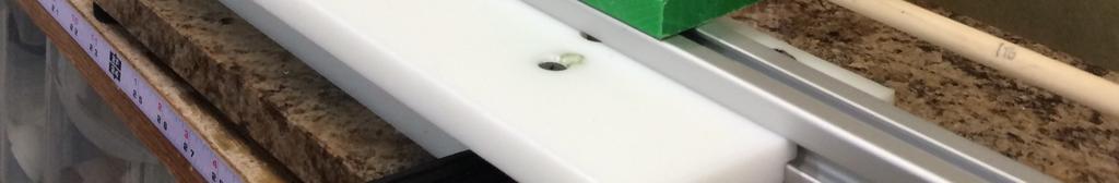
6 1. Set Up The ferrule end of the rod section to be wrapped is mounted in the collet chuck and the outboard end is supported in one or more V block stations. A second smaller chuck is provided for the smaller male ferrules on 3 piece rods. The rod section to be copied is mounted in the lower V-groove and secured with the toggle clamp. Alternately a story stick can be mounted in the V-groove. The laser needs to be aligned. First we set up the angle of the laser line in the horizontal plane using the white setup block. Thumb Wheel Vert angle Adjustment Nylon Set Screw Adjust horizontal angle to 90 deg by turning the thumb wheel on the laser housing. Lock in place with the nylon set screw. Adjust vertical angle to 90 deg by rotating the block holding the laser. Lock in place with the black knob. V 1.2 page 6


7 The entire laser assembly can be moved left or right on the aluminum track and locked in place with the small black knob. Thread spools are mounted on a spindle and secured with the steel thumb wheel. Tapered copper ferrules are used on each side to keep the spool perfectly centered on the spindle. The spindle is mounted on a 1/8 dia rod and the magnet pulls it up against the gap adjustment disc. Thread tension is changed by moving the disc closer or farther away from the magnet. The disc is a tight fit on the rod and it takes some effort to move it. The thread routing is shown here. The counter weight provides take-up when unwinding a wrap. The steel knob on the spool carriage can be used to rewind thread on the spool and return the weight to the up position. Weight can be increased by adding 3/8-16 nuts. Note that the tip tops have slits for ease of threading. The right hand thread goes thru the lower final guide and the left thread thru the upper guide. I like to adjust the tension such that the weight almost allows the spool to unwind. V 1.2 page 7


8 Between wraps, thread is parked on the small extension spring. Simply pull the thread up against and into the spring while bending it with a free finger. Once secured, cut the thread on the knife edge embedded in the frame. The cylindrical thread alignment gage is used to adjust the climb angle of the wraps. Here we are using oversize orange thread for clarity. First this alignment gage must be calibrated. Hold the white setup block against the rod and move the carriage to get a perfect 90 degree angle of thread to rod. Now raise the cylindrical gage up against the thread. If the thread is not aligned with the center red mark, screw the cylinder in or out to achieve alignment. Once aligned, you can adjust the climb angle by moving the carriage left or right of the red line to get the proper climb for the tightest possible wraps. The center line (red line) on the gage is at 90 degrees which is zero climb angle. Note from the photos that the tiptop guiding the thread is mounted on a hex head screw and there is a second tiptop above that guides the thread from the left hand spool. You can rotate the hex head screws to make sure both threads are on the same centerline. V 1.2 page 8


9 2. Rod Wrapping Here we discuss the mechanics of operating the Laser Guided Rod Wrapper. The techniques described are the methods that I use. Your techniques should be made easier using this wrapper. The ferrule end of either the butt or tip sections are chucked in the collet. Two collets are provide with the machine, a large one for 2 pc rods and a smaller one for the smaller tip ferrules of 3 pc rods. Collets are change by loosening the set screw that secures the collet to the encoder shaft. The ferrule is inserted into the collet and tightened by hand. Be sure to push the ferrule all the way into the collet. A couple of layers of masking tape on the ferrule will improve the grip. Mount your story stick marked with the guide locations in the V groove at the base of the head stock. Now move the carriage left or right to align the laser on the ferrule tips. Now move the story stick to align the end of ferrule mark with the laser and clamp in place with the miniature toggle clamp. Since the laser does have some width, do your alignment with either the right or left edge of the beam. There are two outboard supports to hold the free end. Secure with the fabric covered elastic bands. V 1.2 page 9


10 Mount a small rubber band on the rod using a crochet hook. Loop it thru twice and then roll it up on the guide foot. Using the laser, align the guide with the guide location mark on the story stick. If you want to be double sure that the guide does not move, apply some automotive detailing tape to the tip of the left hand foot. Now make 2 wraps by hand over the foot and overlap the thread over these two wraps. Now reset the counter to zero and start wrapping. I generally go about 10 wraps and then push the wraps tight with my thumbnail on each flat while reversing the rotation. I then cut the tag end. The counter resolves each rotation into 100 steps and subtracts counts when reversing. You can use the thread angle guide to set the climb angle which determines how tight the current wrap is crowded against the previous wrap. When the thread is directly over the red line, it is being applied at a right angle to the rod. Obviously, too much climb angle result in over wrapping and too little produces a open V 1.2 page 10


11 spiral. You adjust the climb angle by moving the carriage with the fine adjustment knob. For this guide I have wrapped 2 manual turns plus 25 on the counter. Now I will make the single trim wrap. First I mark the thread for the end of the trim wrap. Then unwind to place the mark over the alignment rod. Check the counter and unwind exactly one turn and mark the thread again over the alignment rod. Now ink the tread between the two marks. Now wrap forward to 31 on the meter and pack tightly. Back up to turn 27, insert the pull loop, return to 30, cut the thread and pull thru. Now we have a completed wrap with 27 turns of the base color, the 28 th wrap is black plus 5 additional wraps of the base color. I generally wrap all the left hand feet first and then come back and wrap the right hand feet. V 1.2 page 11
12 3. Notes The laser is powered by (4) AAA batteries. There is a slide switch on the battery case. This case is mounted to the frame with double-sided tape and is easily removed to change batteries. The counter is powered by a 9 Volt dc wall adaptor. Plug it into the rear of the box and it is ready to go. If power is inadvertently interrupted, the count is retained when power is restored. This electronic counter is programmable for many uses. The programming mode is locked-out to prevent inadvertent changes. The counter s manual is provided with the wrapper and we will provide the access code if you wish to make changes. I generally wrap with the least amount of thread tension as measured at the rod about 10 to 15 grams. This makes it easier to flatten the wraps with a burnisher. The pinion gear is secured to the shaft with a set screw. It can be accessed thru the half moon slot in the platform when the carriage is removed. We also offer a Wrap Finishing Station that handles 4 sections from start to finish. Check it out at V 1.2 page 12
Bertram Binder. 2 String & 4 String Versions. Operating Manual. V 4.2 Cork Disc Tension Control. Visit
 Bertram Binder 2 String & 4 String Versions Operating Manual V 4.2 Cork Disc Tension Control Visit www.quinchat.webs.com for videos Binder Manual v 4.2 page1 Binder Design Change This edition of the operating
MobileTrak5 Installation Instructions
 MobileTrak5 Installation Instructions PLEASE OPEN ALL BOXES & CHECK TO MAKE SURE YOU HAVE ALL PIECES REQUIRED READ ALL INSTRUCTIONS BEFORE STARTING Tools Required for Assembly 7/16, 1/2 Wrench Phillips
MODEL H-9 HEAVY DUTY BENCH-TYPE UNDERCUTTER INSTRUCTIONS
 MODEL H-9 HEAVY DUTY BENCH-TYPE UNDERCUTTER INSTRUCTIONS CAPACITY: Between centers - 32" long x 12" diameter. Between roller V- supports - 35" long x 17" diameter. Maximum armature weight - 200 lbs. SAW
ABM International, Inc.
 ABM International, Inc. Lightning Stitch required 1 1.0: Parts List head and motor assembly (Qty. 1) Reel stand (Qty. 1) Needle bar frame clamp (Qty. 1) Motor drive (Qty. 1) 2 Cable harness with bracket
ABM International, Inc. Navigator Assembly Manual
 ABM International, Inc. 1 1.0: Parts List Tablet (Qty. 1) Tablet mount (Qty. 1) NOTE: Mount may appear and operate different then image below Control Box (Qty. 1) Motor Power Supply (Qty. 1) 2 X-axis motor
FLIP TARP SINGLE & DOUBLE UNDERBODY TRAILERS
 1-800-248-7717 1002 N. 15th Street, Middlesboro, KY 40965 FLIP TARP SINGLE & DOUBLE UNDERBODY TRAILERS INSTALLATION INSTRUCTIONS Congratulations on your purchase of a Mountain Flip Tarp Trailer system.
The Portable Open Source 3D Printer
 http://web.archive.org/web/201502142011/http://www.tantillus.org/build_3.html Page 1 of 12 captures 12 Oct 12 - Feb 15 The Portable Open Source 3D Printer Home Start Case X/Y Axis Extruder Z Axis Electronics
INSTALLATION OF WELLS SUPER QUICK CHUCK LEFT HAND ON RED WING LATHE
 DENTAL, INC. TECHNICAL BULLETIN Q824-022510 5860 FLYNN CREEK ROAD READ ALL INSTRUCTIONS P.O. BOX 106 BEFORE PROCEEDING COMPTCHE, CALIFORNIA, U.S.A. 95427 SAVE THIS FOR FUTURE REFERENCE www.wellsdental.com
SCHACHT STANDARD FLOOR LOOMTM
 SCHACHT STANDARD FLOOR LOOMTM FL3109 FL3111 FL3113 FL3115 FL3121 FL3123 FL3125 FL3127 FL3310 FL3312 FL3314 FL3316 FL3322 FL3324 FL3326 FL3328 Assembly instructions LOW CASTLE LOOM IN MAPLE Find out more
Code Product Qty 1 Top Vertex 3 2 Hot End Housing 1 3 Bottom Vertex 3 4 Print Platform Lock 3 5 End Stop Holder 3 6 Filament Feeder Motor Bracket 1 7
 List of Parts Code Product Qty 1 680mm Extrusion 3 2 Power Supply 1 3 240mm Extrusion 9 4 42mm Nema 17 Stepper Motor 3 5 Slider-Hotend Connecting Rod 6 6 48mm Nema 17 Stepper Motor 1 7 Linear Rail with
Assembly Instructions
 18' W x 10' H or 12' H Peak Style Frame Assembly Assembly Instructions Before you start: 2+ individuals recommended for assembly, approximate time 3 hours. Recommended tools: Power Drill, Safety Glasses,
Due to possible damage in shipping, the vertical stop assembly has been removed from this machine.
 Due to possible damage in shipping, the vertical stop assembly has been removed from this machine. To assemble, insert the threaded rod through the shroud opening in the top of the machine. Start the four
MAIN PARTS
 MAIN PARTS 7 8 9 10 11 12 13 1 2 3 17 4 5 6 01 02 03 04 05 12 23 34 45 56 13 24 35 46 57 14 25 36 47 58 15 16 26 27 37 38 48 49 59 60 06 07 08 09 10 17 18 28 29 39 40 50 51 61 62 19 30 41 52 63 20 21 31
WOLF PUP LOOM TM & WOLF PUP LT LOOM TM
 WOLF PUP LOOM TM & WOLF PUP LT LOOM TM Assembly Instructions FL3000 FL3006 FL3009 WOLF PUP WOLF PUP LT Find out more at schachtspindle.com Schacht Spindle Company 6101 Ben Place Boulder, CO 80301 p. 303.442.3212
Hubble GOTO Installation Instruction (1.3, 04/30/2014)
") Hubble GOTO Installation Instruction (1.3, 04/30/2014) 1. Preparation... 1 1.1 Tools required... 1 1.2 AZ GOTO Drive Parts List...1 1.3 ALT GOTO Drive Parts List... 1 2. The Azimuth motor drive installation...2
Hubble GOTO Installation Instruction (1.3, 04/30/2014) 1. Preparation... 1 1.1 Tools required... 1 1.2 AZ GOTO Drive Parts List...1 1.3 ALT GOTO Drive Parts List... 1 2. The Azimuth motor drive installation...2
INSTALLATION TORSION SPRING FRONT OR REAR MOUNT LOW HEADROOM. 1 Cutting Vertical Track. 2 Fully Adjustable Jamb Brackets
 TORSION SPRING FRONT OR REAR MOUNT LOW HEADROOM Wayne Dalton, a division of Overhead Door Corporation P.O. Box 67, Mt. Hope, OH., 44660 Supplemental insert Copyright 2015 Wayne Dalton, a division of Part
25-200H. 12 Planer / Jointer. with Helical Cutterhead. Parts List.
 25-200H 12 Planer / Jointer with Helical Cutterhead 4001824 Parts List www.rikontools.com CABINET ASSEMBLY PARTS EXPLOSION & PARTS LIST KEY NO. DESCRIPTION KEY NO. DESCRIPTION 1 Pan Head Screw M6x12 P25-200H-1
Continuum Frame Assembly Instructions
 Continuum Frame Assembly Instructions Copyright January 1, 2017 Jim M. Bagley, GraceWood, Inc (Reproduction Prohibited) Version 2.2 Table of Contents Continuum Frame Table of Contents... i Warranty...ii
Insolroll Clutch Operated Shades Installation Instructions Installation Instructions
 All clutch operated shades are shipped fully assembled and ready for installation. Mounting screws are not provided. Screws for chain guide installation to meet the child safety standards are provided.
Gared Pro-S Portable Backstop
 Models: 9616 & 9618 Installation, Operation and Maintenance Instructions Please read all instructions before attempting installation or operation of these units SAVE THESE INSTRUCTIONS FOR FUTURE USE PUBLICATION
VARIABLE SPEED WOOD LATHE. Model DB900 INSTRUCTION MANUAL
 VARIABLE SPEED WOOD LATHE Model DB900 INSTRUCTION MANUAL 1007 TABLE OF CONTENTS SECTION...PAGE Technical data.. 1 General safety rules....1-3 Specific safety rules for wood lathe.....3 Electrical information.4
Using the RhAT II Universal
 Using the RhAT II Universal To use the Original RhAT Tools, the main shaft of the machine had to be rotated to the setting position, either mechanically or electronically, while the needle bar was disengaged
18600 Angular Momentum
 18600 Angular Momentum Experiment 1 - Collisions Involving Rotation Setup: Place the kit contents on a laboratory bench or table. Refer to Figure 1, Section A. Tip the angular momentum apparatus base on
Q-Zone Hoop-Frame. Assembly Instructions. Copyright July 11, 2018 Grace Company (Reproduction Prohibited) Version 1.8
 Version 1.8") Q-Zone Hoop-Frame Assembly Instructions Copyright July 11, 2018 Grace Company (Reproduction Prohibited) Version 1.8 Table of Contents Table of Contents... i Warranty... ii Parts List Box 1...iii Box 2...
Q-Zone Hoop-Frame Assembly Instructions Copyright July 11, 2018 Grace Company (Reproduction Prohibited) Version 1.8 Table of Contents Table of Contents... i Warranty... ii Parts List Box 1...iii Box 2...
The Queen Quilter Professional Quilters Kit Frame
 The Queen Quilter Professional Quilters Kit Frame Assembly Instructions Table of Contents: Before you begin......................... Pg. 2 Wood parts............................. Pg. 3 Hardware..............................
N. 15th Street, Middlesboro, KY FLIP TARP DUMP BODY INSTALLATION INSTRUCTIONS
 1-800-248-7717 1002 N. 15th Street, Middlesboro, KY 40965 FLIP TARP DUMP BODY INSTALLATION INSTRUCTIONS Congratulations on your purchase of a Mountain Flip Tarp Dump Body tarping system. With tarping systems
H2-50 Hydrogen Generator Field Update
 This field update is intended to provide extra protection in the event the H2 generation cell fractures or cracks. Please add the additional parts to your H2-50 as soon as possible. Please take a digital
The Useless Machine. DIY Soldering Edition. Instruction Guide v0004
 The Useless Machine DIY Soldering Edition Instruction Guide v0004 TM For the best outcome, follow each step in order. We recommend reading this guide entirely before you get started. Tools required: Soldering
E LJ TJ LASER MEASURING DEVICE INSTRUCTIONS
 Green Sight Laser Distance Measuring Laser 6 meter Aluminum Rail Weighted Steel Bases! WARNING: This product can expose you to Titanium Dioxide, which is known to the State of California to cause cancer.
30AUTO Speed Lathe Manual
 30AUTO Speed Lathe Manual Standard Features 3/4 HP Motor Air-Collet Closure 1800 RPM, Single Speed Electric Brake Cast Housing 5C Collets 3 Phase / 240 Volts DESCRIPTION: The Crozier Model 30AUTO Automotive
HQ Pole Upgrade Kit for HQ Adjustable Table and HQ QuilTable Assembly Instructions 1
 HQ Pole Upgrade Kit for HQ Adjustable Table and HQ QuilTable Assembly Instructions QF09775 The pole upgrade kit can be used with or without the QF09700 HQ Precison-Glide track upgrade kit. What s Included
OPERATIONS MANUAL. Port-O-Slitter
 Tapco Products Company The World Leader in Specialty Tools for the Professional Port-O-Slitter OPERATIONS MANUAL General instructions, set up, accessories and guide to using your portable precision slitting,
OPERATION AND MAINTENANCE HANDBOOK D407270XA
 OPERATION AND MAINTENANCE HANDBOOK D407270XA vers. 1.0 Thank you for choosing one of Silca s high quality key cutting machines. This machine has been designed, tested and produced in our factory using
Side Winder R o u t e r L i f t.
 Woodpeckers PRECISION WOODWORKING TOOLS Side Winder R o u t e r L i f t. INSTALLATION INSTRUCTIONS The wrench handle must be pointing left in order to fully insert or remove it. Lift Wrench Once fully
Lumber Smith. Assembly Manual. If you are having problems assembling the saw and need assistance, please contact us at:
 Lumber Smith Assembly Manual If you are having problems assembling the saw and need assistance, please contact us at: 804-577-7398 info@lumbersmith.com 1 Step 1 Safety Carefully read the Owners Manual.
How to program the digital speed display (This is factory set and will only need to be programmed if the unit is replaced)
") How to program the digital speed display (This is factory set and will only need to be programmed if the unit is replaced) 1. Press and hold the set button (top left corner) until the display shows Fun
How to program the digital speed display (This is factory set and will only need to be programmed if the unit is replaced) 1. Press and hold the set button (top left corner) until the display shows Fun
Assembly Instructions 10 X 10 Aluminum Roof Support
 Assembly Instructions 10 X 10 Aluminum Roof Support Aluminum Roof Support Bolt Package 16-5/16 X 2 ¼ SS Bolt 24-5/16 X 1 SS Bolt 40-5/16 SS Nylon Lock Nuts 16-5/16 SS Flat Washers 28-4 ½ Wood Screws 36-1
FBX-PA-2AC. Third edition : April No
 FBX-PA-2AC Third edition : April 2006 No. 060058 INTRODUCTION Thank you very much for purchasing Kansai Special FBX series. Read and study this Instruction Manual carefully before you start any of the
Replacing the Reciprocator on the SWF Compact Series Machine (601C and 1201C)
") Follow the instructions below to replace the reciprocator in the SWF Compact series machines. The tools required can be found in the tool kit that came with the machine. Preparation 1. First, place the
Follow the instructions below to replace the reciprocator in the SWF Compact series machines. The tools required can be found in the tool kit that came with the machine. Preparation 1. First, place the
Hydraulic Clamp Carrier. Installation & Operation Manual
 Hydraulic Clamp Carrier Installation & Operation Manual Hydraulic Clamp Carrier Installation & Operation Manual Quick Machinery Company 8272 Peninsula Drive Kelseyville, CA 95451 phone: (707) 272-6719
Reversing Gear. Shay Reversing Gear
 Shay Nelson Riedel Nelson@NelsonsLocomotive.com Initial: 9/23/03 Last Revised: 06/05/2004 The reversing gear is another one of those pieces I've been putting off. The reason for the postponement was that
POP PLUS / SPIDER SET-UP INSTRUCTIONS
 POP PLUS / SPIDER SET-UP INSTRUCTIONS 1 Place system frame on floor with screws indicating top. Expand upwards & outwards and secure frame connectors. Pop-Up display systems are made to be set-up and taken
Instructions & Parts SM100B SM400 K025S1 K005
 Instructions & Parts SM100B SM400 K025S1 K005 Table of Contents 2 SM100B/SM400 Manual Engraver Machine Diagram Pantograph Operation Setup & Layout Engraving & Changing Cutters Adjusting Depth of Cut &
M14 MODULAR CHASSIS SYSTEM (MOD 1) INSTRUCTION MANUAL. West Springfield, MA Phone: (866) FAX: (413)
 INSTRUCTION MANUAL. West Springfield, MA Phone: (866) FAX: (413)") M14 MODULAR CHASSIS SYSTEM (MOD 1) INSTRUCTION MANUAL Troy Industries, Inc. WWW.TROYIND.COM West Springfield, MA 01089 Phone: (866) 788-6412 FAX: (413) 383-0339 Thank You M14/M1A MODULAR CHASSIS SYSTEM
M14 MODULAR CHASSIS SYSTEM (MOD 1) INSTRUCTION MANUAL Troy Industries, Inc. WWW.TROYIND.COM West Springfield, MA 01089 Phone: (866) 788-6412 FAX: (413) 383-0339 Thank You M14/M1A MODULAR CHASSIS SYSTEM
BABY WOLF LOOM. Assembly Instructions for Knocked-Down Looms
 BABY WOLF LOOM Assembly Instructions for Knocked-Down Looms BEFORE YOU BEGIN Please read through the directions before beginning to assemble your loom. Unpack the loom parts carefully. Do not throw away
400A 40113V, 401A 40120V, & 401AL 40120VL ALUMINUM VERTICAL 4000 LB LIFT INCLUDES SCREW LEG ASSEMBLY INSTRUCTIONS
 12/11/07 PAGE 1 OF 12 400A 40113V, 401A 40120V, & 401AL 40120VL ALUMINUM VERTICAL 4000 LB LIFT INCLUDES SCREW LEG ASSEMBLY INSTRUCTIONS Thank you for purchasing our product! *Please read these instructions
LANDING GEAR. 1. Fit landing gear into slots on bottom of fuselage.
 LANDING GEAR 1. Fit landing gear into slots on bottom of fuselage. 4. Use channel-lock pliers to press blind nuts into position (note: drilled hole should be slightly smaller than shaft of blind nut for
BLADE N BULLET BLIND Cabela s Item Number:
 BLADE N BULLET BLIND Cabela s Item Number: 466353 Visit cabelas.com or call 1-800-237-4444 for assistance. TABLE OF CONTENTS 2 3 4-13 Table of Contents Package Contents Instructions for Use Visit cabelas.com
Band-Master ATS Nano Pneumatic Banding Tool Operating Instructions
 Band-Master ATS 601-118 Nano Pneumatic Banding Tool CONTENTS 601-118 Overview... 3 Safety.... 5 Initial Tool Set-up... 5 Regulator assembly mounting... 5 Attach tool head to regulator.... 6 Operating instructions...
Astro-Physics Inc. 400QMD Lubrication/Maintenance Guide
 Astro-Physics Inc. 400QMD Lubrication/Maintenance Guide The following guidelines should be followed to lubricate the three main parts of the 400QMD mount. The QMD stands for Quartz Micro-Drive controller.
MODEL NO.: MI PARTS BREAKDOWN
 MODEL NO.: MI-76350 PARTS BREAKDOWN MAGNUM DRILL PRESS ASSEMBLY INSTRUCTIONS MODEL MI-76350 Before you begin to assemble your drill press, review the parts breakdown and keep it ready for reference. Start
48 in. X 96 in. 500 Pound Capacity Motorized Overhead Storage Unit Installation Guide [OPTION B] MODEL # PRM4X8 Patent Pending
![48 in. X 96 in. 500 Pound Capacity Motorized Overhead Storage Unit Installation Guide [OPTION B] MODEL # PRM4X8 Patent Pending](/thumbs/81/83353561.jpg "48 in. X 96 in. 500 Pound Capacity Motorized Overhead Storage Unit Installation Guide [OPTION B] MODEL # PRM4X8 Patent Pending") 48 in. X 96 in. 500 Pound Capacity Motorized Overhead Storage Unit Installation Guide [OPTION B] MODEL # PRM4X8 Patent Pending 1 Table of Contents Table of Contents PAGES Installation Support 3 Safety
48 in. X 96 in. 500 Pound Capacity Motorized Overhead Storage Unit Installation Guide [OPTION B] MODEL # PRM4X8 Patent Pending 1 Table of Contents Table of Contents PAGES Installation Support 3 Safety
Assembly, Use and Care Instructions
 Assembly, Use and Care Instructions Product #336677 Instruction #1068318 Rev. F Thank you for purchasing a Caldwell Lead Sled DFT 2. The Lead Sled DFT 2 comes to you partially assembled. It will require
Tools: Sharpie, Square, Vise, Hack saw, Ruler, Punch, Hammer, File. 2. Cut the stock Place stock in vise and cut with hack saw
 Purpose: MAKE CATAPULT ARM Step 1 Tools: Sharpie, Square, Vise, Hack saw, Ruler, Punch, Hammer, File Materials: Flat aluminum ½ inch stock (see picture below) Gloves required 1. Pick up the aluminum ½
Removing the Z-Axis lead screw
 Page 1 of 8 TITLE: Sabre Z-Axis Lead Screw Replacement Procedure Gerber FastFact #: 5048 Supplied by: Gerber Hardware Support Last Modified: June 14, 2007 Summary: Tools used: The following procedure explains
Pneumatic Clamp Carrier. Installation & Operation Manual
 Pneumatic Clamp Carrier Installation & Operation Manual Pneumatic Clamp Carrier Installation & Operation Manual Quick Machinery Company 8272 Peninsula Drive Kelseyville, CA 95451 phone: (707) 272-6719
Usage and Assembly Instructions
 Instructions #1037447 Product #795234 Revision D Usage and Assembly Instructions Rear Fork (Buttstock) Rear Fork Lock Knob Rail Lock Knob Front Fork (Forend) Rails Tilt Friction Knob Rail Extension Locks
STAR TOOL SUPPLY / GRAND TOOL SUPPLY
 R8 COLLETS SERIES 333 : SUPERIOR IMPORT SERIES 330 : (Concentricity guaranteed to 0.000) Size 1/32** 1995502 1/16 1995104 7169005 3/32 1995106 7169010 1/8 1995108 7169012 5/32 1995110 7169015 3/16 1995112
Installation instructions for FC14S Forward Controls for Shadow ACE and Aero 1100
 Installation instructions for FC14S Forward Controls for Shadow ACE and Aero 1100 It is highly recommended that you use a thread lock compound such as Loctite brand on all threads to keep them from vibrating
# in 1 Metal Worker Auxiliary Operating Instructions
 340 Snyder Avenue, Berkeley Heights, NJ 07922 www.micromark.com MMTechService@micromark.com Tech Support: 908-464-1094, weekdays, 1pm to 5 pm ET #86556 3 in 1 Metal Worker Auxiliary Operating Instructions
HARDINGE Installation booklet For: Dead-Length Collet Adaptation Chucks Stationary Collet
 HARDINGE Installation booklet For: Dead-Length Collet Adaptation Chucks Stationary Collet Read the enclosed instructions and recommendations before any installations CONTENTS Dead-Length Collet Adaptation
SERIES I MILLING MACHINES
 INSTALLATION, OPERATION, MAINTENANCE, AND PARTS LIST SERIES I MILLING MACHINES TP5260 Revised: August 29, 2005 Manual No. M-450 Litho in U.S.A. Part No. M -0009500-0450 June, 2003 MAINTENANCE PROCEDURES
SuperTrack Parts List
 SuperTrack Parts List [indicates number for 6 lane tracks] SuperTrack Installation Instructions www.supertimer.com 1-800-654-2088 1 Track Instruction Manual (this booklet) 2 Start sections [3] Start Gate
INSTRUCTION MANUAL LEG PRESS OPTION OF ELITE GYM
 INSTRUCTION MANUAL LEG PRESS OPTION OF ELITE GYM QUESTION? As a quality home gym supplier we are committed to your complete satisfaction. If you have questions, or find missing or damaged parts, we will
KIT. Assembly Instructions. HayDay, LLC
 KIT Assembly Instructions HayDay, LLC 1-800-732-1654 www.stablegrazer.com Read completely through the assembly instructions before starting assembly. The Stable Grazer Kit comes in two boxes. Remove all
Pneumatic Clamp Carrier. Installation & Operation Manual
 Pneumatic Clamp Carrier Installation & Operation Manual Pneumatic Clamp Carrier Installation & Operation Manual Quick Machinery Company 8272 Peninsula Drive Kelseyville, CA 95451 phone: (707) 272-6719
Assembly Instructions
 InTandem Table System November 20 InTandem Table System - Worksurface #4 x/" 4 wood screw power beam Tools Provided T-0 Extended Torx Driver T-25 Torx Driver Additional Tools Required Soft protective
Installation Guide. Mounting Kit for Mounting Philips Avalon CTS Cordless Fetal Transducer System on Wall, 2'' Post, Rail, or Slide-on Mounting Plate
 Installation Guide Mounting Kit for Mounting Philips Avalon CTS Cordless Fetal Transducer System on Wall, 2'' Post, Rail, or Slide-on Mounting Plate The purpose of this guide is to: 1. Describe mounting
The Virgo/Libra Steam Engine
 The Virgo/Libra Steam Engine Congratulations on becoming the owner of a Virgo or Libra Steam Engine. With careful use and maintenance it will give many years of satisfying performance. Contents 1) Notes
SHERLINE Mill Digital Readout
 SHERLINE Mill Digital Readout P/N 8100 (Inch) Digital Readouts in the modern machine shop Digital readouts are popular on full-size shop mills because they make the life of a machinist much simpler. They
SETUP INSTRUCTIONS If you would like to tell us about your experience with your setup instructions please us at
 207 VK-964 General Layout 0 0 Plan View www.classicexhibits.com SETUP INSTRUCTIONS If you would like to tell us about your experience with your setup instructions please email us at info@classicexhibits.com
MBM Sprint 3000 Booklet Maker
 MBM Sprint 3000 Booklet Maker Instruction Manual Provided By http://www.mybinding.com http://www.mybindingblog.com SPRINT 3000 BOOKLETMAKER OPERATION MANUAL IMP oper3500.doc Page 1 23/01/2004 CONTENTS
MyStudio VS53 Versa Sweep Setup Instructions
 MyStudio VS53 Versa Sweep Setup Instructions MISSION STATEMENT Pro Cyc, Inc. is the world leader in design and sales of modular infinity backgrounds. Our studio systems are recommended by every major company
30DC Speed Lathe Manual
 30DC Speed Lathe Manual The Crozier Model 30DC Speed Lathe is our most popular model. It has many standard features not found on any other machine in its class or price range. Standard Features 3/4 HP
DRILL GRINDING ATTACHMENT
 DRILL GRINDING ATTACHMENT To suit TM6025Q TOOL AND CUTTER GRINDER OPERATION S MANUAL 1 0º 270º 90º 180º INTRODUCTION Before grinding any cutters, you must set up the attachment to suit the type of cutter
Greenslade & Company, Inc. USA
 Greenslade Recess TIR Gaging System Patent # 5,182,865 Gage Application: The Recess TIR Gage is designed to make the measurement of the concentricity of the screw s drive system and head O.D. to its shank
JVice Care and Maintenance Thanks for purchasing a Jvice. If properly looked after your Jvice will give a lifetime of tying pleasure.
 JVice Care and Maintenance Thanks for purchasing a Jvice. If properly looked after your Jvice will give a lifetime of tying pleasure. Although it is manufactured from highest quality materials any metal
Nancy s Knit Knacks LLC 4 Yard Option Upgrade Kit Assembly Instructions and User Manual
 Nancy s Knit Knacks LLC 4 Yard Option Upgrade Kit Assembly Instructions and User Manual Thank you for purchasing our 4 Yard Option (4YO) Upgrade Kit. To install this upgrade you are simply going to assemble
SPIDA SAW OPERATIONS MANUAL
 SPIDA SAW OPERATIONS MANUAL CM SERIAL NUMBER. OCTOBER 2000 CONTENTS Page description 1.) Contents 2.) Safety First 3.) CM Overview 4.) CM Specifications 5.) CM Installation 6.) CM Operation Setting the
Taper Attachment for G4016 Gear Head Lathe
 Taper Attachment for Gear Head Lathe MODEL H0775 INSTRUCTION SHEET COPYRIGHT AUGUST, 2004 BY GRIZZLY INDUSTRIAL, INC. WARNING: NO PORTION OF THIS MANUAL MAY BE REPRODUCED IN ANY SHAPE OR FORM WITHOUT THE
installation guide 1 GUIDE#: pwb-assault-004
 assault WAKEBOARD tower installation guide INSTALLATION SUPPORT 1 important information This Aerial wakeboard tower fits motor boats with 76-108 inch wide beam widths. This measurement is taken from the
Durst Laborator 138 S
 Durst Laborator 138 S -I- G139 Durst Laborator 138 S Durst Laborator G 139 Servicing instructions L 1 3 8 S G 139 - Replacing the counterweight spring The special tool required for this purpose is supplied
RYOBI 10 IN (254 MM) TABLE SAW MODEL NO. BT REPAIR SHEET
 TABLE SAW MODEL NO. BT REPAIR SHEET") RYOBI 0 IN (2 MM) TABLE SAW MODEL NO. BT00- REPAIR SHEET 2 RYOBI 0 in. (2 mm) TABLE SAW - MODEL NO. BT00- FOR MITER TABLE ASSEMBLY, REFER TO FIGURE B FOR BLADE GUARD ASSEMBLY, REFER TO FIGURE E FOR RIP
RYOBI 0 IN (2 MM) TABLE SAW MODEL NO. BT00- REPAIR SHEET 2 RYOBI 0 in. (2 mm) TABLE SAW - MODEL NO. BT00- FOR MITER TABLE ASSEMBLY, REFER TO FIGURE B FOR BLADE GUARD ASSEMBLY, REFER TO FIGURE E FOR RIP
Machining. Module 6: Lathe Setup and Operations. (Part 2) Curriculum Development Unit PREPARED BY. August 2013
 Curriculum Development Unit PREPARED BY. August 2013") Machining Module 6: Lathe Setup and Operations (Part 2) PREPARED BY Curriculum Development Unit August 2013 Applied Technology High Schools, 2013 Module 6: Lathe Setup and Operations (Part 2) Module Objectives
Machining Module 6: Lathe Setup and Operations (Part 2) PREPARED BY Curriculum Development Unit August 2013 Applied Technology High Schools, 2013 Module 6: Lathe Setup and Operations (Part 2) Module Objectives
M2 Antenna Systems, Inc. Model No: 2M5WL
 M2 Antenna Systems, Inc. Model No: 2M5WL SPECIFICATIONS: Model... 2M5WL Frequency Range... 144 To 148 MHz *Gain... 16.84 dbi Front to back... 22 db Typical Beamwidth... E=26 H=29 Feed type... T Match Feed
SINGER 531B-8BL. From the library of: Superior Sewing Machine & Supply LLC
 SINGER 53B-8BL PERSPECTIVE THREAD TENSION, GUIDE, NEEDLE PLATE i SINGER 4 THREAD TENSION, GUIDE, NEEDLE PLATE 3 Fig. No. Parts No. Quantity Name of Parts Fig. No. Parts No. Quantity Name of Parts 0698
The Festival Assembly Instructions
 The Festival Assembly Instructions Toll Free: 866.768.8465 Hours: 9-5 Monday-Friday EST www.homeplacestructures.com Package ships as shown CONTACT INFORMATION: HomePlace Structures 301 Commerce Drive New
MODEL T " HELICAL CUTTERHEAD INSTALLATION INSTRUCTIONS
 MODEL T27696 12" HELICAL CUTTERHEAD INSTALLATION INSTRUCTIONS For questions or help with this product contact Tech Support at (570) 546-9663 or techsupport@grizzly.com Introduction The Model T27696 indexable
Brother Industries, Ltd. Nagoya, Japan
 4. 2001. This service manual has been compiled for explaining repair procedures of the MODEL XL-6562, XL6452, XR- 46. This was produced based on up-to-date product specifications at the time of issue,
re3d Assembling Gigabot: "Flatpack"
 re3d Assembling Gigabot: "Flatpack" Your Gigabot was assembled, calibrated, tested, and taken apart for shipping purposes. All you need to do is reassemble it, and you're ready to go! Written By: Chris
Quill Stop V2 Installation Guide 11/16/2014
 Thank you for purchasing the Quill Stop for the Sieg X3 (Grizzly G0463) and SX3 (Grizzly G0619) mills. Your feedback is always appreciated. Please email questions and comments to gregpriest@cox.net. What
PRS Retro Z-Axis Installation
 PRS Retro Z-Axis Installation Page -1- PRS Retro Z-Axis Installation This document is a guide to installing the PRS Retro Z-axis on early ShopBot models. It describes installation for PR models with PK299
SERVICE PARTS LIST PAGE 1 OF 6 BASE ASSEMBLY SPECIFY CATALOG NO. AND SERIAL NO. WHEN ORDERING PARTS 12" SLIDING COMPOUND MITER SAW
 PAGE 1 OF 6 BASE ASSEMBLY 00 0 CATALOG NO. EXAMPLE: SPECIFY CATALOG NO. AND NO. WHEN ORDERING PARTS 6955-20 1 02-80-0050 Thrust Bearing (1) 2 05-80-0510 M5 x 12mm Flat Head T-20 Screw (5) 3 05-81-0135
3,500/4,500lb. Vertical Cable Feighner Lift
 3,500/4,500lb. Vertical Cable Feighner Lift CAUTION - PUT SAFETY FIRST 1. Before attempting to install or operate this lift, study and fully understand the proper operating procedures and safety precautions
OPERATIONS MANUAL. Port-O-Slitter
 OPERATIONS MANUAL Port-O-Slitter General instructions, set up, accessories and guide to using your portable precision slitting, rib forming and perforating system Saves hours on large siding jobs! Featuring:
TOOL LIST FOR TAILGATE HIDDEN LATCH & LINK ASSY FOR FORD FLARESIDE TRUCKS
 TOOL LIST FOR TAILGATE HIDDEN LATCH & LINK ASSY FOR 53-87 FORD FLARESIDE TRUCKS Vise Grip Clamps C-clamps Sharpie Marker Ball Peen Hammer Center Punch 3/8 or 1/2 Drill 5/32, 7/32, 9/32, and 3/8 Drill Bits
It is highly recommended that you use a thread lock compound such as Loctite brand on all threads to keep them from vibrating loose.
 Installation instructions for FC12 Forward Controls for Kawasaki Vulcan 750 It is highly recommended that you use a thread lock compound such as Loctite brand on all threads to keep them from vibrating
TOOLS AND INSTALLATION
 TOOLS AND INSTALLATION Safe, leak-free operation of any high-pressure system is dependent on correctly prepared and installed connections. This section outlines proper instructions for the machining and
M2 Antenna Systems, Inc. Model No: 20M5LD
 M2 Antenna Systems, Inc. Model No: 20M5LD SPECIFICATIONS: Model... 20M5LD Frequency Range... 14.0 14.350 MHz *Gain (Full Band)... 10.2 dbi Typical Front to back... 23 db Typical Beamwidth... E=50 / H=66