Pneumatic Clamp Carrier. Installation & Operation Manual
|
|
|
- Henry Wright
- 5 years ago
- Views:
Transcription

1 Pneumatic Clamp Carrier Installation & Operation Manual
2
3
4
 272-6719 fax: (707) 278-0102 e-mail: service@quickmachinerycomp")
5 Pneumatic Clamp Carrier Installation & Operation Manual Quick Machinery Company 8272 Peninsula Drive Kelseyville, CA phone: (707) fax: (707) web:
6
7 Contents Introduction...9 Installation...11 Locate a Clean, Level, Protected Space...11 Assemble the Frame Install the Angle Beams Install the Panel Flattener Install the Front Rest Install the Clamp Tightener Carriage Connect the Air Hoses Connect the Electrical Wires Install the Mounting Plates onto Each Clamp Mount the Clamps onto the Clamp Carrier Frame Apply Bates Glue Release to the Clamps and Clamp Screws Oil the Clamp Thrust Washers Operation...21 Apply Bates Glue Release to the Clamps and Clamp Screws Start Up the Machine Load Stock Into the Clamps Tighten the Clamps Rotate the Carrier (Manual Mode) or Rotate the Carrier (Automatic Mode) Loosen the Clamps One Hour for Complete Cycle Shut Down the Machine Maintenance...25 Daily Weekly Yearly As Needed Electrical Diagrams...27 Legend for Electrical Diagrams on the Following Pages
8 8


9 Introduction Thank you for your purchase of a Quick Pneumatic Clamp Carrier. Your machine has been designed for many years of trouble-free performance. Please read this installation & operation manual and follow its instructions to correctly install, operate and maintain your Clamp Carrier. Doing so will help ensure optimum productivity and reliability of your machine. 9
10
11 Locate a Clean, Level, Protected Space Installation 1. Locate a clean, level space on a concrete fl oor to install the Clamp Carrier. Be sure to select a location where the rear of the machine will be up against a wall, or else build a steel fence to enclose the rear of the Clamp Carrier, to protect people from walking into the clamps that project from the rear of the machine. 11
12 Installation 12
, with the platform for the electric drive motor, is the right-hand leg (as viewed when standing in front of the machine.")
13 Assemble the Frame Installation 1. Place the two A-frame legs (1, 2) upright and into position. The larger leg (1), with the platform for the electric drive motor, is the right-hand leg (as viewed when standing in front of the machine. Note: In the following 3 steps, leave the bolts a little loose, then tighten them all at once in step 5, after the frame has been squared up. 2. Attach the foot connector bars (5) to the feet on the Clamp Carrier legs, according to their markings. 3. Install the front shaft (17) onto the tops of the two A-frame legs (1,2). Bolt the shaft bearings (50) to the tops of the two legs (1,2). Match up the sprocket on the end of the shaft with the sprocket on the gear reducer. Couple the two sprockets together with the two-row chain (13). Connect the two ends of the two-row chain together with the link pin. Install the chain cover over the two-row chain. 4. Check and make sure that the frame is square. Also check and make sure that the frame is level both horizontally and vertically. 5. Tighten all of the bolts installed in steps 2 and 3. 13
14 Installation Make sure T-shaped plates are attached to the CENTER chain.. (Clamps will be installed later.) Install the Angle Beams 1. Attach the angle beams (18) to the angle beam attachment tabs on the three chains (88, 89, 90). Onto each set of attachment tabs, attach two angle beams (18), facing each other. 14 On the center chain (89), attach the two angle beams with T-shaped plates (36), bolts (38), lock washers (33) and nuts (34). Make sure the plates welded-on tabs points toward the right-hand side of the machine, to keep the clamps from sliding into contact with the center chain. On the two side chains, attach the two angle beams with rectangular plates (19), bolts (38), lock washers (33) and nuts (34).
15 Installation Install the Panel Flattener 1. Attach the two long connecting bars (22) to the overhead panel fl attener beam (21) with two bolts (55) per bar. 2. Attach the two short connecting bars (23) to the overhead panel fl attener beam (21) with one (56) bolt per bar. 3. With the panel fl attener beam lying on the fl oor, attach the free ends of the long connecting bars (22) to the upper holes on the brackets that are welded to the middles of the front legs. 4. Swing the panel fl attener beam up into position. Attach the free ends of the short connecting bars (23) to the brackets (51 on drawing A, page 12) that are welded to the tops of the legs. 5. Tighten all bolts securely. 6. Remove the square cap from one end of the lower panel fl attener beam tube, slide the panel fl attener (54) onto the panel fl attener beam, and replace the square cap. 7. (Air hoses will be attached later). 15
16 Installation Install the Front Rest 1. Attach the square ends (62) of the front rest positioners (65) to the brackets on the bottoms of the front legs. 2. Attach the front rest (24) to the rounded ends (25) of the front rest positioners (65). 3. Attach the cylinder ends (61 & 61) of the front rest air cylinders (43 & 44) to the lower holes on the brackets that are welded to the middles of the front legs. The right-hand cylinder has tee fi ttings; the left-hand cylinder has elbow fi ttings. The fi ttings should face downward. 4. Attach the small ends (66 & 67) of the front rest air cylinders (43 & 44) to the holes (66 & 67) in the sides of the front rest. 5. Tighten all bolts securely. Install the Clamp Tightener Carriage 1. Remove the rectangular cap from one end of the front rest, slide the clamp tightener carriage (27) onto the front rest, and replace the cap. 16
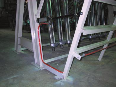
17 Installation 85 Connect the Air Hoses 1. Connect a (5 hp) compressed air supply to the fi lter/lubricator/regulator air inlet (84). 2. Connect the air hose (72) from the air distribution block (85) to the air hose on the panel fl attener beam (21). Connect the air hose (71) on the panel fl attener beam (21) to the panel fl attener (54). 3. Connect the air hoses (73 & 74) from the solenoid valve (86) to the horizontal connectors on the tee fi ttings on the right-hand front rest cylinder (43). Connect the air hoses (75 & 76) from the vertical connectors on the tee fi ttings on the right-hand front rest cylinder (43) to the elbow fi ttings on the left-hand front rest cylinder (44). 4. Connect the air hose (59) from the Clamp Tightener (28) to the air distribution block (85). Connect the Electrical Wires 1. Connect the wires from the panel fl attener limit switch (79) and left-side emergency stop button box (82) to the terminal strip inside the electrical box, noting their numbered markings. 2. Connect the machine to suitable 3-phase power. 17

 into the clamp mounting plate positioning fi xture (160) that was included with the machine.")
18 Installation The steps below will adjust the clamp mounting plates for uniform clamp positioning on the Carrier. If desired, the clamps can be adjusted later for individual mounting angle and axial position. Install the Mounting Plates onto Each Clamp 1. Assemble the clamp mounting hardware onto the clamp (29): two mounting plates (30), two spacers (31), two bolts (37), four fl at washers (32) and two nuts (34). Leave the nuts loose for now. 2. Place the clamp (29) into the clamp mounting plate positioning fi xture (160) that was included with the machine. Make sure that the clamp is up tight against the three front positioning posts (161, 162, 163) and up tight against the one rear positioning post (164). Hold the mounting plates fl at against the rear positioning plate (165, also see photo at lower right). 3. Tighten the two nuts securely, but not so tight that they crush the clamp bodies. 18
19 Installation Mount the Clamps onto the Clamp Carrier Frame 1. Rotate the Carrier until a section of two angle beams (18) is facing the front rest (24). Bring the front rest in, so clamps can rest on it. 2. Loosen the bolts that attach the upper of the two angle beams. Lift one end of the beam up at an angle. 3. While holding the upper beam up at an angle, place a row of clamps onto the lower angle beam. The clamps will rest on the lower angle beam at the rear (with the beam inserting into the lower slots of the clamp mounting plates), and on the front rest at the front. 4. Lower the upper angle beam down, making sure that the upper beam inserts into the upper slots in the clamp mounting plates. Tighten all the section s bolts (19) securely. 5. Rotate the Carrier by TWO sections until half of the sections are fi lled. Doing so will help keep the Carrier in balance. 6. Repeat steps 2 through 5 until all sections are fully outfi tted with clamps. 19
20 Installation Apply Bates Glue Release to the Clamps and Clamp Screws This is very important! Taking an hour to do this now will save many hours of future clean-up time. It is MUCH easier (and much better for the equipment) to apply regular coatings of Glue Release than it is to chisel rock-hard, dried glue build-up off of uncoated clamps! A free sample of Bates Glue Release should have been supplied with your machine. 1. Apply a thin coating of Bates Glue Release to the tops of the clamp bodies (where the wood will contact the clamps), and apply a thick coating of Glue Release to the clamp screws. Apply with a cloth, sponge, paint brush (our preferred method), or spray it on. Run the clamp jaws all the way up and back to distribute the Glue Release evenly over the screw threads. The Glue Release will only partially dry, leaving a thick, waxy fi lm in the troughs of the screw threads. Note: Since Bates Glue Release is a lubricant as well as a glue release product, you will not need to oil the screws if you use the Glue Release regularly. 2. Make it a habit to ALWAYS keep your clamps coated with a waxy layer of Bates Glue Release; it should be part of your daily and/or weekly routine. This will keep clean-up time to a bare minimum, and will maximize the service life of your clamps. Oil the Clamp Thrust Washers 1. Oil the thrust washers that are located between the clamp nuts and the clamp bodies, with 30-weight motor oil or equivalent. 20

21 Apply Bates Glue Release to the Clamps and Clamp Screws Operation This is normally done at the END of each working day. However, if it has not been done yet, it MUST be done before starting your very fi rst production run. Please see page 23 for details. Start Up the Machine 1. Switch the machine on by switching the Power switch to "On". Load Stock Into the Clamps 1. Place stock to be glued, with glue already applied to the edges of the boards, into the clamps. Tighten the Clamps 1. Push the Panel Flattener away from yourself, to disengage it from it s stop at the end of the Panel Flattener beam, then roll the Flattener to a position that s in between the fi rst two clamps that you want to tighten. Energize the Panel Flattener by pressing down on it s air valve toggle. The Flattener comes down and fl attens the stock. 2. Set the Clamp Tightener air wrench for rotation in the "Tighten" direction. Bring the Clamp Tightener up into position and press the trigger to tighten the clamp. (Adjust the Clamp Tightener's tightening torque if needed.) Move on to the next clamp and tighten it. 3. De-energize the Panel Flattener by pulling up on it s toggle. Position it between the next two clamps to be tightened, and energize it, fl attening the panel. Tighten the two clamps. 4. Continue fl attening and tightening until all of the clamps are tight. 21

22 Operation Rotate the Carrier (Manual Mode) or Turn the Mode switch to MANUAL. 2. Make sure that the Panel Flattener is all the way to the right side, where it contacts the limit switch. This is a safety feature that only allows the Carrier to rotate when the Panel Flattener is out of the way of the rotating clamps. 3. Press and hold the Rotate UP button for a second or two, rotating the Carrier in reverse until the clamps are positioned 4" or so above the front rest, then release the button. 4. Press the Front Rest OUT button. The front rest moves out away from the clamps. 5. Press and hold the Rotate DOWN button until the next section of clamps is positioned 4 or so above the front rest, then release the button. 6. Press the Front Rest IN button. The front rest moves in toward the clamps. 7. Press and hold the Rotate DOWN button again, until the Carrier automatically stops rotating, with the clamps touching down lightly on the front rest. Release the button. (The clamps should touch down lightly on the front rest. If the Carrier rotates too little, the clamps will fl oat in the air above the front rest; too much and you will not be able to slide the clamps from side to side to set up for new panel sizes. Adust the Carrier rotation limit switch [LS1, see page 25, As Needed Maintenance] if needed.) 22
23 Rotate the Carrier (Automatic Mode) 1. Turn the Mode switch to AUTO. Operation 2. Press the Cycle START button. The Carrier automatically rotates in reverse, the front rest comes out, the Carrier rotates forward, the front rest comes back in, and the Carrier rotates forward until the clamps rest lightly on the front rest. Loosen the Clamps 1. Set the Clamp Tightener air wrench for rotation in the "Loosen" direction. Use the Clamp Tightener to loosen the clamps one by one, bringing the Clamp Tightener up into position on each clamp, engaging the clamp, and pressing the trigger until the clamp s rear jaw is at the desired position. One Hour for Complete Cycle 1. Continue the above steps for all the Carrier sections. You should completely rotate the Carrier in 60 minutes or so, which is suffi cient time for the glue to dry. However, it is best to wait 24 hours before machining the panel, to avoid sunken joints caused by planing off the swollen glue joints before the moisture has had time to equalize throughout the panel. Shut Down the Machine 1. While unloading the last batch of panels for the day, scrape the dried, squeezed-out glue from the clamps and apply a coating of Bates Glue Release to the clamp bodies and screws, as per the instructions on page 23. Make it a habit to always keep your clamps coated with a waxy layer of Bates Glue Release; it should be part of your daily and/or weekly routine. This will keep clean-up time to a bare minimum, and will maximize the service life of your clamps. 2. Shut down the machine by switching the Power switch to OFF. 23
24
25 Daily Maintenance 1. Drain the water from the air fi lter on the fi lter/lubricator/regulator assembly. 2. While unloading the fi nal batch of panels for the day, scrape dried, squeezed-out glue off of the clamps, then apply a coating of Bates Glue Release to the tops of the clamp bodies (where the wood will contact the clamps), and to the clamp screws. Apply the Glue Release with a cloth, sponge, paint brush (our preferred method), or spray it on. Make it a habit to always keep your clamps coated with a waxy layer of Bates Glue Release. Note: Since Bates Glue Release is a lubricant as well as a glue release product, you will not need to oil the screws if you use the Glue Release regularly. Weekly 1. Fill the oiler bowl on the fi lter/lubricator/regulator assembly with 10-weight oil. 2. Oil the clamp nuts and thrust washers with 30-weight motor oil. Yearly 1. Change the oil in the Electric Motor Drive s gear reducer. Use Mobil gear oil #630. As Needed 1. Adjust the clamp carrier rotation limit switch (LS1 on opposite page) for correct Carrier rotation. 2. Replace the wear parts in the Clamp Tightener air wrench motor: # and # : 25
26 Maintenance 26
27 Electrical Diagrams Legend for Electrical Diagrams on the Following Pages COS1 Flush Select Switch COS2 Select Switch LS Limit Switch PB1 Emergency Stop Button PB2 - PB8 Push Buttons T1 - T3 Timers R1 - R6 Relays 27
28 Electrical Diagrams 28
29 Electrical Diagrams 29
30 Electrical Diagrams 30
31
Pneumatic Clamp Carrier. Installation & Operation Manual
 Pneumatic Clamp Carrier Installation & Operation Manual Pneumatic Clamp Carrier Installation & Operation Manual Quick Machinery Company 8272 Peninsula Drive Kelseyville, CA 95451 phone: (707) 272-6719
Hydraulic Clamp Carrier. Installation & Operation Manual
 Hydraulic Clamp Carrier Installation & Operation Manual Hydraulic Clamp Carrier Installation & Operation Manual Quick Machinery Company 8272 Peninsula Drive Kelseyville, CA 95451 phone: (707) 272-6719
The Virgo/Libra Steam Engine
 The Virgo/Libra Steam Engine Congratulations on becoming the owner of a Virgo or Libra Steam Engine. With careful use and maintenance it will give many years of satisfying performance. Contents 1) Notes
Assembly Instructions. Table of Contents
 HQ Little Foot Assembly Instructions Back of Handi Quilter, Inc. 501 North 400 West North Salt Lake, UT 84054 1-877-697-8458 Front of 2015 Handi Quilter, Inc. www.handiquilter.com Printed in the United
SPIDA SAW OPERATIONS MANUAL
 SPIDA SAW OPERATIONS MANUAL CM SERIAL NUMBER. OCTOBER 2000 CONTENTS Page description 1.) Contents 2.) Safety First 3.) CM Overview 4.) CM Specifications 5.) CM Installation 6.) CM Operation Setting the
FLIP TARP SINGLE & DOUBLE UNDERBODY TRAILERS
 1-800-248-7717 1002 N. 15th Street, Middlesboro, KY 40965 FLIP TARP SINGLE & DOUBLE UNDERBODY TRAILERS INSTALLATION INSTRUCTIONS Congratulations on your purchase of a Mountain Flip Tarp Trailer system.
Side Winder R o u t e r L i f t.
 Woodpeckers PRECISION WOODWORKING TOOLS Side Winder R o u t e r L i f t. INSTALLATION INSTRUCTIONS The wrench handle must be pointing left in order to fully insert or remove it. Lift Wrench Once fully
400A 40113V, 401A 40120V, & 401AL 40120VL ALUMINUM VERTICAL 4000 LB LIFT INCLUDES SCREW LEG ASSEMBLY INSTRUCTIONS
 12/11/07 PAGE 1 OF 12 400A 40113V, 401A 40120V, & 401AL 40120VL ALUMINUM VERTICAL 4000 LB LIFT INCLUDES SCREW LEG ASSEMBLY INSTRUCTIONS Thank you for purchasing our product! *Please read these instructions
Thank you for purchasing out product! *Please read these instructions and follow them step by step. *
 Page 1 of 7 AD17 AA DS 4 X 16 T12 Thank you for purchasing out product! *Please read these instructions and follow them step by step. * STEP 1. Slide two support posts (REF. # 24) into the two outside
MODEL T28173/T28174 ROLLER TABLES INSTRUCTIONS
 MODEL T28173/T28174 ROLLER TABLES INSTRUCTIONS FOR MODELS MFD. SINCE 10/17 For questions or help with this product contact Tech Support at (570) 546-9663 or techsupport@grizzly.com Rails Rollers Reversible
Inspection. Assembly Install the springs. 1. Discard the 0-rings. 2. Clean all parts in cleaning solvent.
 6010-34 Inspection 3. Install the springs. 1. Discard the 0-rings. 2. Clean all parts in cleaning solvent. 3. If spring test equipment is available, check the tension of each spring according to the specifications
N. 15th Street, Middlesboro, KY FLIP TARP DUMP BODY INSTALLATION INSTRUCTIONS
 1-800-248-7717 1002 N. 15th Street, Middlesboro, KY 40965 FLIP TARP DUMP BODY INSTALLATION INSTRUCTIONS Congratulations on your purchase of a Mountain Flip Tarp Dump Body tarping system. With tarping systems
The Phoenix. Professional Quilting Frame. Copyright January 1, 2016 Jim M. Bagley, GraceWood, Inc (Reproduction Prohibited) Version 2.
 Version 2.") The Phoenix Professional Quilting Frame Copyright January 1, 2016 Jim M. Bagley, GraceWood, Inc (Reproduction Prohibited) Version 2.1 1 The Phoenix Professional Quilting Frame Parts List Box 1...3 Box
The Phoenix Professional Quilting Frame Copyright January 1, 2016 Jim M. Bagley, GraceWood, Inc (Reproduction Prohibited) Version 2.1 1 The Phoenix Professional Quilting Frame Parts List Box 1...3 Box
M4 Foot Operated Underpinner Instruction Manual
 M4 Foot Operated Underpinner Instruction Manual M4 Walker Rd, Bardon Hill, Coalville, Leicestershire LE67 1TU, England Tel. +44 (0)130 1692, Fax +44 (0)130 16929 e mail sales@framerscorner.co.uk M4 Underpinner
Lumber Smith. Assembly Manual. If you are having problems assembling the saw and need assistance, please contact us at:
 Lumber Smith Assembly Manual If you are having problems assembling the saw and need assistance, please contact us at: 804-577-7398 info@lumbersmith.com 1 Step 1 Safety Carefully read the Owners Manual.
18000 HDL FOUR POST LIFT LB CAPACITY INSTALLATION AND OWNER'S MANUAL
 18000 HDL FOUR POST LIFT 18000 LB CAPACITY INSTALLATION AND OWNER'S MANUAL WARNING! Do not raise a vehicle unless the front stops are in place, the parking brake is set, and the wheels are chocked. Stay
southpaw enterprises, inc.
 southpaw enterprises, inc. Instruction Sheet C-STAND 7100 Store these instructions in a safe place or with the enclosed maintenance checklist Take time to familiarize yourself with the use and maintenance
Removing the Z-Axis lead screw
 Page 1 of 8 TITLE: Sabre Z-Axis Lead Screw Replacement Procedure Gerber FastFact #: 5048 Supplied by: Gerber Hardware Support Last Modified: June 14, 2007 Summary: Tools used: The following procedure explains
Depending on the size you ordered you will have either 5 Foot sections which will build the 10 Foot frame or 6 Foot sections which will build the 12
 XL Quilting Frame 1 Depending on the size you ordered you will have either 5 Foot sections which will build the 10 Foot frame or 6 Foot sections which will build the 12 Foot frame Printed 2 June 2014 Updated
STARTING SERIAL NUMBER PARTS LIST FOR. Wellsaw MODEL 600 METAL CUTTING BAND SAW
 STARTING SERIAL NUMBER 11075 PARTS LIST FOR Wellsaw MODEL 600 METAL CUTTING BAND SAW Wellsaw 2829 N. Burdick, Kalamazoo, MI 49004 Phone: 269-345-1132 Fax: 269-345-0095 Rev 171005 INSTALLATION, OPERATION
1. VERIFY ALL COMPONENTS
 R INSTALLATION INSTRUCTIONS RAGNAR+ODEN FACE MOUNT, BYPASSING. VERIFY ALL COMPONENTS BASE KIT Track stand-offs Front trolley kit * Rear trolley kit * Allen keys Track fastener kit - wood - Bottom guide
JARVIS. Model25CL-4,5,6 Hock Cutter and Loin Dropper. 25CL--5 Front Legs and Horns. 25CL--4 Hind Legs and Horns. 25CL--6 Loins
 Model25CL-4,5,6 Hock Cutter and Loin Dropper 25CL--4 Hind Legs and Horns 25CL--5 Front Legs and Horns 25CL--6 Loins EQUIPMENT SELECTION... Ordering No. TABLE OF CONTENTS... Page 25CL--4... 4025007 25CL--5...
HD installation guide
 JANUS INTERNATIONAL 1 866 562 2580 www.janusintl.c o m 1950 1950HD installation guide RIGHT DRIVE END SHOWN LH OPPOSITE LEFT TENSION END SHOWN RH OPPOSITE PUSH-UP OPERATION 1950 1950HD SHOWN A rolling
OPERATION, SERVICE AND PARTS INSTRUCTION MANUAL 1813 BENDING TABLE FOR 881 HYDRAULIC BENDER
 OPERATION, SERVICE AND PARTS INSTRUCTION MANUAL 1813 BENDING TABLE FOR 881 HYDRAULIC BENDER Read and understand this material before operating or servicing this bender. Failure to understand how to safely
S48-L12-SC AND G48-L12-GC STEEL PORTA-DOCK S82 SC 6 X 12 PLATFORM AND G82 GC 6 X 12 PLATFORM
 PAGE 1 OF 6 PORTA-DOCK, INC. S48-L12-SC AND G48-L12-GC STEEL PORTA-DOCK S82 SC 6 X 12 PLATFORM AND G82 GC 6 X 12 PLATFORM Thank you for purchasing our product! *Please read these instructions and follow
TOOL LIST FOR TAILGATE HIDDEN LATCH & LINK ASSY FOR FORD FLARESIDE TRUCKS
 TOOL LIST FOR TAILGATE HIDDEN LATCH & LINK ASSY FOR 53-87 FORD FLARESIDE TRUCKS Vise Grip Clamps C-clamps Sharpie Marker Ball Peen Hammer Center Punch 3/8 or 1/2 Drill 5/32, 7/32, 9/32, and 3/8 Drill Bits
PORTA-DOCK, INC. AP17 APD DS 4 X 16 T12 AW17 CPD DS 4 X 16 T12
 Page 1 of 7 PORTA-DOCK, INC. AP17 APD DS 4 X 16 T12 AW17 CPD DS 4 X 16 T12 *For Beige Decking Add the Letter B to Model* Thank you for purchasing out product! *Please read these instructions and follow
Band-Master ATS Nano Pneumatic Banding Tool Operating Instructions
 Band-Master ATS 601-118 Nano Pneumatic Banding Tool CONTENTS 601-118 Overview... 3 Safety.... 5 Initial Tool Set-up... 5 Regulator assembly mounting... 5 Attach tool head to regulator.... 6 Operating instructions...
B-Too Drilling and Tapping Machine Instruction and Maintenance Manual
 B-Too Drilling and Tapping Machine Instruction and Maintenance Manual Thank you for your purchase of the B-Too Drilling and Tapping Machine. Please read and understand this short operation manual. Our
Maintenance Information
 16601023 Edition 2 January 2014 Air Impact Wrench 2705P1 Maintenance Information Save These Instructions Product Safety Information WARNING Failure to observe the following warnings, and to avoid these
Fisher 667 Diaphragm Actuators Size 80 and 100
 Instruction Manual 667 Size 80 and 100 Actuators Fisher 667 Diaphragm Actuators Size 80 and 100 Contents Introduction... 1 Scope of Manual... 1 Description... 2 Specifications... 2 Maximum Pressure Limitations...
HYDRAULIC CONTROL DETAILS PARTS LIST
 Always give model number, serial number and part number when ordering repair parts. HYDRAULIC CONTROL DETAILS PARTS LIST REF NO. PART NUMBER DESCRIPTION 1 101939 Hydraulic Tank 2 101940 Hydraulic Tank
PowerLock. Installation Instructions. Attention Dealers: Please give this owners manual to the customer when the product is delivered.
 Serving the Truck & Trailer Industry Since 1944 FOR Attention Dealers: Please give this owners manual to the customer when the product is delivered. Call 800-535-9545 www.aeroindustries.com Indianapolis,
Daily Maintenance. 2. Insert bobbin cases in to rotary hooks. Make sure bobbin thread is not over 2 inches long. Close bobbin case covers.
 Rotary hook 1. Open bobbin case covers and remove bobbin cases. Use brush to remove lint build up in and around rotary hooks. Compressed air may also be used. Daily Maintenance Cle aning Oiling Rotary
SUPER PRO GUN & SUPER PRO GUN II
 MAGNUM VENUS PRODUCTS Maintenance & Repair Manual Part No. M6707-1-1 Revision 04.14.01 Maintenance & Repair Corporate HQ & Mfg. Phone: (727) 573-2955 Fax: (727) 571-3636 Email: info@magind.com Web: www.magind.com
Strata. urniture. Adriana Instructions. Parts in the Arm Box: Parts in the Body Box: Watch our assembly videos at
 1A Watch our assembly videos at www.strataf.com/videos Parts in the Arm Box: Arm - Outside View Arm - Inside View 1B Parts in the Body Box: Back Deck x 1 Seat Deck x 1 with the Feet attached Back Panel
AUTOMATIC ADVANCE MANUAL
 AUTOMATIC ADVANCE MANUAL AVL Looms, Inc. 3851 Morrow Lane, Suite #9 Chico, CA 95928-8305 530 893-4915 530 893-1372 fax # info@avlusa.com www.avlusa.com Copyright 2009 TABLE OF CONTENTS Page # I. Parts.........................
Hardware and Components:
 Hardware and Components: (A) 4X 5/16 x 1 Carriage Bolt (B) 2X 5/16 x 2-1/4 Carriage Bolt (C) 2X 5/16 x 3-1/4 Hex Bolt (D) 2X 5/16 x 3/4 Hex Bolt (E) 2X 5/16 x 1-1/4 Hex Bolt (F) 5/16 x 2-1/4 Hex Bolt (G)
LEG CURL IP-S1315 INSTALLATION INSTRUCTIONS
 LEG CURL IP-S35 INSTALLATION INSTRUCTIONS Copyright 2009. Star Trac by Unisen, Inc. All rights reserved, including those to reproduce this book or parts thereof in any form without first obtaining written
installation guide
 JANUS INTERNATIONAL 1 866 562 2580 w w w. j a n u s i n t l. c o m 2000 2500 3000 installation guide RIGHT DRIVE END SHOWN LH OPPOSITE LEFT TENSION END SHOWN RH OPPOSITE PUSH-UP OPERATION 2000 2500 3000
How to program the digital speed display (This is factory set and will only need to be programmed if the unit is replaced)
") How to program the digital speed display (This is factory set and will only need to be programmed if the unit is replaced) 1. Press and hold the set button (top left corner) until the display shows Fun
How to program the digital speed display (This is factory set and will only need to be programmed if the unit is replaced) 1. Press and hold the set button (top left corner) until the display shows Fun
Hardware and Components:
 Hardware and Components: (A) 5/16 x 2 Hex Bolt (B) 5/16 x 2-1/4 Hex Bolt (C) 5/16 x 2-1/2 Hex Bolt (D) 4X 5/16 x 3/4 Hex Bolt (E) 4X 5/16 x 1-1/4 Hex Bolt (F) 11X 5/16 Flat Washer (G) 12X 5/16 Nylock Nut
A59 APD & A86 CPD 5'X 16' SW ALUMINUM PORTA-DOCK
 Page 1 of 5 PORTA-DOCK, INC. A59 APD & A86 CPD 5'X 16' SW ALUMINUM PORTA-DOCK *For Beige Decking Add the Letter B to model* Thank you for purchasing our product! *Please read these instructions and follow
MODEL 83 Pail Handler
 MORSE MFG. CO., INC. 727 West Manlius Street P.O. Box 518 East Syracuse, NY 13057-0518 Phone: 315-437-8475 Fax: 315-437-1029 Email: service@morsemfgco.com Website: www.morsemfgco.com COPYRIGHT 2005 MORSE
BEAST THE. Tube and Pipe Notcher Operating Instructions. Notches In Bends Straight Notches. Angled Notches. Offset Notches
 Copyright (c) 2007 J D SQUARED INC. www.jd2.com THE BEAST Tube and Pipe Notcher Operating Instructions Notches In Bends Straight Notches Angled Notches PATENT PENDING Offset Notches Assembly After unpacking
PHG-1000X. Owner s Manual HOME GYM
 HOME GYM Owner s Manual WWW.BODYSOLID.COM THERE IS A RISK ASSUMED BY INDIVIDUALS WHO USE THIS TYPE OF EQUIPMENT. TO MINIMIZE RISK, YOU MUST FOLLOW THESE RULES:! " # $ % & ' ( ) * + ' (, ' " -. *, * ) )
Sunrise Deck Assembly Instructions for Kingston Left
 Sunrise Deck Assembly Instructions for Kingston Left It s easiest to build the deck frame first like it will be lying on its back and then after all 4 legs and horizontals are in place, tip the deck toward
Large Wood Windmill Assembly Instructions
 CROW S NEST (TOP VIEW) TOWER (SIDE VIEW) 0 QTY 2 2 ITEM QTY 2 QTY QTY 8 QTY 8 QTY 4 TOP TOP TOP 47 9 QTY 4 QTY 4 QTY 4 QTY 4 QTY 4 ITEM 6 ITEM 7 ITEM 8 ITEM 3 ITEM 9 ITEM 4 ITEM 2 ITEM 5 47 Leg QTY 4 42.5
1. Turn off or disconnect power to unit (machine). 2. Push IN the release bar on the quick change base plate. Locking latch will pivot downward.
. 2. Push IN the release bar on the quick change base plate. Locking latch will pivot downward.") Figure 1 Miniature Quick Change Applicators, of the end feed type, are designed to crimp end feed strip terminals to prestripped wires. Each applicator is set up to accept the strip form of certain specific
Figure 1 Miniature Quick Change Applicators, of the end feed type, are designed to crimp end feed strip terminals to prestripped wires. Each applicator is set up to accept the strip form of certain specific
Orbital Test Stand. Operations and Assembly Manual. Department of Mechanical Engineering Northern Arizona University Flagstaff, AZ 86011
 Orbital Test Stand Operations and Assembly Manual Department of Mechanical Engineering Northern Arizona University Flagstaff, AZ 86011 TABLE OF CONTENTS 1.0 Components List... 2 2.0 Assembly Instructions...
Slide the stock rubber tank mount caps onto the ends of the CS-1 tank mount:
 RYCA CS-1 BODY PARTS INSTALLATION GUIDE [The CS-1 installation guides should be used as supplements to the videos found on our Youtube Channel. There is no strict order to the build process, but it is
Giraud Tool Company, Inc.
 Motor Upgrade for Gracey Trimmer This package is intended to allow the user to upgrade their Gracey trimmer with a higher rpm motor and convenience features not found in the production offering. This upgrade
Fig Remove chain cover plate bolts. Fig Remove hammer member. Fig Loosen set screws at base of 12-tooth sprocket.
 Fig. 17.2. Remove chain cover plate bolts. Fig. 17.1. Remove hammer member. Fig. 17.3. Remove chain cover plate. Fig. 17.4. Loosen set screws at base of 12-tooth sprocket. Page 61 Fig. 17.5. Remove socket
3,500/4,500lb. Vertical Cable Feighner Lift
 3,500/4,500lb. Vertical Cable Feighner Lift CAUTION - PUT SAFETY FIRST 1. Before attempting to install or operate this lift, study and fully understand the proper operating procedures and safety precautions
SECTION 9: PARTS Cabinet & Base
 SECTION 9: PARTS 5 5-1 48 3 75 90 49 4 91 333 46 47 30 89 88 2 34 33 37 36 78 35 32 326 316 49 42 45 83 84V2 43 1 7 8 9 12 87 10 11 Cabinet & Base 31 17 20 40 39 136 41 135 85 86 8 28 26 18 19 21 19 370
Operating Instructions
 Operating Instructions Holding the material against the angle gauge slide it into the forming head. Be sure that the material remains against the gauge until work is finished. NOTE: This machine will handle
PowerLock. Installation Instructions. Attention Dealers: Please give this owners manual to the customer when the product is delivered.
 Serving the Truck & Trailer Industry Since 1944 PowerLock Attention Dealers: Please give this owners manual to the customer when the product is delivered. Call 800-535-9545 www.aeroindustries.com Indianapolis,
767, 777, DC-10, L-1011, MD-11 Tow Bar Equipment Manual
 514 MECKLEM LANE, ELLWOOD CITY, PENNSYLVANIA 16117 www.hallindustries.com E-mail: service@hallindustries.com 767, 777, DC-10, L-1011, MD-11 Tow Bar Equipment Manual Use This Manual for 1. Operating Procedures
Taper Attachment for G4016 Gear Head Lathe
 Taper Attachment for Gear Head Lathe MODEL H0775 INSTRUCTION SHEET COPYRIGHT AUGUST, 2004 BY GRIZZLY INDUSTRIAL, INC. WARNING: NO PORTION OF THIS MANUAL MAY BE REPRODUCED IN ANY SHAPE OR FORM WITHOUT THE
Staple Specification:
 H-1027, H-1028 H-3064 PNEUMATIC STICK STAPLER stapler specifications Dimensions: L x H x W 13.5 x 8.75 x 6" Weight (Without Fasteners) Compressed Air: Maximum psi: Recommended Operating Pressure: Air Consumption:
OPERATION & MAINTENANCE MANUAL
 OPERATION & MAINTENANCE MANUAL AUTOMATIC PECAN CRACKER Food Processing Equipment and Machinery Specializing in the Pecan Industry Mailing: PO Box 817, Mansfield, Louisiana 71052 Located: 280 Independence
Introduction to Carpentry Power Tools
 Youth Explore Trades Skills Introduction to Carpentry Power Tools Description s use power tools every day, and the ability to use these tools correctly and safely is paramount. In this Activity Plan, students
Q-Zone Hoop-Frame. Assembly Instructions. Copyright July 11, 2018 Grace Company (Reproduction Prohibited) Version 1.8
 Version 1.8") Q-Zone Hoop-Frame Assembly Instructions Copyright July 11, 2018 Grace Company (Reproduction Prohibited) Version 1.8 Table of Contents Table of Contents... i Warranty... ii Parts List Box 1...iii Box 2...
Q-Zone Hoop-Frame Assembly Instructions Copyright July 11, 2018 Grace Company (Reproduction Prohibited) Version 1.8 Table of Contents Table of Contents... i Warranty... ii Parts List Box 1...iii Box 2...
Castle Frame Assembly Table AT-8. Diagnostics Manual. Castle, Inc. Petaluma, CA
 Castle Frame Assembly Table AT-8 Diagnostics Manual Castle, Inc. Petaluma, CA 800-282-8338 Solutions Index Adjusting the Tabletop.. 8.01 Adjusting the Fence... 8.02 Aligning the Arm... 8.10 Adjusting Bracket..
HL295. **[Some items below and the next page may have been factory installed at the time of your MAGNATRAC order!] PARTS LIST 1930L
![HL295. **[Some items below and the next page may have been factory installed at the time of your MAGNATRAC order!] PARTS LIST 1930L](/thumbs/96/127020503.jpg "HL295. **[Some items below and the next page may have been factory installed at the time of your MAGNATRAC order!] PARTS LIST 1930L") HL295 Hydro Loader Kit HL295 Version: 04.16 NOTE! Instructions if HL295 is purchased at the time of MAGNATRAC order: Skip Steps 1 thru Step 24, as these items have been factory installed. Start on Step
HL295 Hydro Loader Kit HL295 Version: 04.16 NOTE! Instructions if HL295 is purchased at the time of MAGNATRAC order: Skip Steps 1 thru Step 24, as these items have been factory installed. Start on Step
Model No: TC10. Parts Information: Tyre Changer - Automatic
 Page 1 of 11 1 TC10.01 BODY 2 TC10.02 COLUMN 3 TC10.03 HORIZONTAL ARM ASS'Y 4 TC10.04 WASHER 5 TC10.05 RUBBER FOOT 6 TC10.06 COVER 7 TC10.07 SCREW M14x42 8 TC10.08 PRESS COVER 9 TC10.09 STOP-UP 10 TC10.10
The DeltaGrip System. Safety and Operating Instructions. Trigger. Air Supply Connection. Handle Assembly. Air Line Assembly.
 The DeltaGrip System Safety and Operating Instructions Trigger Air Supply Connection Handle Assembly Air Line Assembly Punch Die Pneumatic Diaphragm Assembly Shackle, Pin & Jam Nut Jaw Frame Shoulder Screw
Item #28187 EASTWOOD BEAD ROLLER INSTRUCTIONS
 Item #28187 EASTWOOD BEAD ROLLER INSTRUCTIONS The Eastwood Bead Roller is a professional metal fabrication tool for producing strengthening ribs in panels used in creating replacement fl oor pans, fi rewalls,
Lockformer / 16 Gauge Speednotch
 Lockformer / 16 Gauge Speednotch INSTALLATION PRELIMINARY: After uncrating, locate unit, with or without base skid, to area of operation. Unbind foot switch cord and cylinder hoses and remove gauge pin
======================================================================================== ( DR / DR) JK WRANGLER MOD RACK
 JK WRANGLER MOD RACK") (10984 4DR / 10982 2DR) JK WRANGLER MOD RACK INSTALLATION SHEET Important Notes: Some brands of windshield light brackets and snorkels may not be compatible with the 10984 MOD Rack System. Body lifts are
(10984 4DR / 10982 2DR) JK WRANGLER MOD RACK INSTALLATION SHEET Important Notes: Some brands of windshield light brackets and snorkels may not be compatible with the 10984 MOD Rack System. Body lifts are
LORON SERVICE MANUAL / PARTS LIST SINGLE DOUBLE PALLET HANDLER CONTENTS: PAGE 1 Lift Truck Requirements General Installation Procedures
 LORON SERVICE MANUAL / PARTS LIST SINGLE DOUBLE PALLET HANDLER CONTENTS: PAGE 1 Lift Truck Requirements General Installation Procedures 2 Mounting Options Stop Block Adjustments 3 General Weekly Inspection
Legacy Woodworking Machinery a division of Phantom Engineering. The Legacy CNC. Assembly Manual
 Legacy Woodworking Machinery a division of Phantom Engineering The Legacy CNC Assembly Manual New Orientation of the Legacy Step one: Re-orientation of the machine Remove the X-axis screw and supports.
Referencing 0,0 position
 Page 1 of 11 TITLE: SABRE X-Axis Lead Screw Replacement Procedure Gerber FastFact #: 2013 Supplied by: Gerber Hardware Support Last Modified: March 1, 2011 Summary: The following procedure explains how
J D SQUARED INC. NOTCH MASTER Tube and Pipe Notcher Operating Instructions
 Copyright (c) 2006 J D SQUARED INC. www.jd2.com NOTCH MASTER Tube and Pipe Notcher Operating Instructions Angled Notches PATENT PENDING Straight Notches Offset Notches Tube Clamp Slider Tube Clamp Exploded
Motorized M3 AX7200 Rotary-Style Gasket Cutter Operating Instructions
 Motorized M3 AX7200 Rotary-Style Gasket Cutter Operating Instructions INTRODUCTION Congratulations! You are the owner of the finest rotary-style gasket cutter in the world. Originally developed and patented
Model 20: Home & Garden Cart
 Model 20: Home & Garden Cart Parts List Step 1: A: Install two ¾ Bolts (C) through the rear trim piece on the Bottom Panel (S) and attach to Lock Nuts. (Lock nuts on bottom side) B: Place left Side Panel
Authority22 Transition Roller for Existing Machines
 Authority22 Transition Roller for Existing Machines Upgrade Packaging 1 per Authority22 14-860241-000 Package Transition Roller Upgrade Kit NOTE: Due to installation requirements, the parts will be packaged
Retractable Tongue Kit Model MPG457 Instructions
 Malone MicroSport Trailer Retractable Tongue Kit Model MPG457 Instructions TM Take a few moments and read through these instructions to familiarize yourself with the step by step assembly process before
TO OPERATE AUTO-GUIDE POWER. 24 Gauge Pittsburgh Operating Instructions FLANGING ATTACHMENT
 24 Gauge Pittsburgh Operating Instructions Holding the material against the angle gauge slide it into the forming head. Be sure that the material remains against the gauge until work is finished. Make
Gared Pro-S Portable Backstop
 Models: 9616 & 9618 Installation, Operation and Maintenance Instructions Please read all instructions before attempting installation or operation of these units SAVE THESE INSTRUCTIONS FOR FUTURE USE PUBLICATION
Bend-Tech Dragon Assembly Manual
 p.1 Bend-Tech Dragon Assembly Manual IMPORTANT: Please read before unpacking. Place shipping container in a wide open area where you will have room to work and assemble this product. Shipping The Dragon
MODELS 49 RA 49 RAZ 49 RAC
 General Safety and Maintenance Manual MODEL grinder featuring a rear exhaust. Model Number Exhaust Direction REAR Throttle Type (L) Lever or (K) Safety Lever Speed 12000 to 14000 R.P.M (13500rpm is standard)
7x --Tailstock Cam Lock
 7x --Tailstock Cam Lock By Magic Brian magicbrian40@yahoo.com Probably the most pleasing mod to have, but often not done through lack of milling facility s This version does NOT require a mill. MATERIALS
Obtained from Omarshauntedtrail.com
 DaveintheGrave's Halloween Props Animated Crawling Skeleton Build a life-size skeleton torso that realistically crawls across the lawn one arm at a time. 1. Motor Base and Linkage Assembly BASE - I used
Model: SCD430 SCD640. Installation & Operation Guide P/N SCD640-95
 Model: SCD430 SCD640 Installation & Operation Guide P/N SCD640-95 Model SCD430 and SCD640 Kurt has two Self-Centering vises, a four-inch jaw width (SCD430) and a six-inch jaw width (SCD640). Jaw opening
HANDLING AND ASSEMBLY INSTRUCTIONS FOR TRUE FOCUS 3.0M, 3.8M AND 4.2M ANTENNAS WITH POLAR MOUNT
 HANDLING AND ASSEMBLY INSTRUCTIONS FOR TRUE FOCUS 3.0M, 3.8M AND 4.2M ANTENNAS WITH POLAR MOUNT Introduction SECTION 1 Thank you for purchasing one of our fine True Focus products. This manual covers the
Main Drive Components
 Pipe and Bolt Threading Machine Main Drive Components 0 0 Rear Centering Head Centering Jaw Set Spiral Pins () 00 Centering Scroll Retaining Ring 0 Rear Bearing 0 Oil Ball Valve () # - x / Screw Motor
SINCE 1922 P UBLICATION N O
 SINCE 1922 GARED SPORTS MICRO-Z SET-UP INSTRUCTIONS VERY IMPORTANT! READ INSTRUCTIONS CAREFULLY AND FOLLOW STEP BY STEP SET-UP PROCEDURE P UBLICATION N O. 5 5 1 7 5 2 9 1 6 Recommended tools and accessories.
OPERATIONAL MANUAL V1.0. Removing/Replacing Blades
 OPERATIONAL MANUAL V1.0 BLUEROCK WS-212 Wire Stripper Removing/Replacing Blades CAUTION!! IMPORTANT!! DANGER!! WARNING!! DISCONNECT MACHINE FROM POWER BEFORE PROCEEDING!! Estimated Completion Time: 90
30DC Speed Lathe Manual
 30DC Speed Lathe Manual The Crozier Model 30DC Speed Lathe is our most popular model. It has many standard features not found on any other machine in its class or price range. Standard Features 3/4 HP
IN 578. Tools Required. Torque Specification: 10mm Socket 7/16 Socket 1/2 Socket 1/2 Wrench 7/16 Wrench 1/8 Allen Wrench.
 Tools Required 2011-C Ford F250/F350 No Drilling into Vehicle is Required 10mm Socket 7/16 Socket 1/2 Socket 1/2 Wrench 7/16 Wrench 1/8 Allen Wrench FL277 x 1 Torque Specification: 1/4 Bolts - 6 Ft Lbs.
SOCCER TABLE. Assembly Instructions
 Updated: 9/30/2015 SOCCER TABLE Assembly Instructions Table of Contents Parts Identifier... 3 Hardware Identifier. 4 Table Assembly Instructions... 5 Table Assembly Pictures..... 6, 7, 8 2 Page Parts Identifier
Strata. urniture. Addison Instructions. Parts in the Arm Box: Parts in the Body Box: Watch our assembly videos at
 1A Watch our assembly videos at www.strataf.com/videos.html Parts in the Arm Box: Arm - Outside View Arm - Inside View Corbels x 4 1B Parts in the Body Box: Back Deck x 1 Seat Deck x 1 Back Panel x 1 with
SHEREX FASTENING SOLUTIONS PNEUMATIC SPIN-SPIN INLINE STYLE RIVET NUT INSTALLATION TOOL SSG-902 MANUAL
 SHEREX FASTENING SOLUTIONS PNEUMATIC SPIN-SPIN INLINE STYLE RIVET NUT INSTALLATION TOOL SSG-902 MANUAL SSG-902 Specifications R.P.M. - 1500 *Air Pressure - 60-90 psi (oiled) Weight - 2 lbs. (0.9 kg) Air
Motorized or Crank Operated Fortress Zipper Track Shade with Housing and Side Track Installation Instructions
 Motorized or Crank Operated Fortress Zipper Track Shade with Housing and Side Track Installation Instructions Tools Needed Drill 3/8 Metal Drill Bit ¼ Masonry Drill Bit Measuring Tape Pencil 4 Level Phillips
Horizontal Cable Systems
 ALUMINUM RAILING INSTALLATION INSTRUCTIONS v2012 orizontal Cable Systems 1) Check Contents Of Packages: Verify that all parts have arrived and that they match the packing list. 1A) Coastal applications:
OPERATIONS MANUAL. Port-O-Slitter
 Tapco Products Company The World Leader in Specialty Tools for the Professional Port-O-Slitter OPERATIONS MANUAL General instructions, set up, accessories and guide to using your portable precision slitting,
Power Train Lift Max. Capacity: 1,250 lbs.
 655 EISENHOWER DRIVE OWATONNA, MN 55060 USA PHONE: (507) 455-7000 TECH. SERV.: (800) 533-6127 FAX: (800) 955-8329 ORDER ENTRY: (800) 533-6127 FAX: (800) 283-8665 INTERNATIONAL SALES: (507) 455-7223 FAX:
FS 1500 Underpinner. Owner s Manual. Volume 516. Know your FS 1500 Underpinner. framingsupplies.com
 Owner s Manual Volume 516 Know your Page 1 Congratulations on your choice of 's FS 1500 underpinner. Prior to shipping, your FS 1500 was completely tested to ensure that you receive a perfectly functioning
SETTING UP THE MODEL 210B-2 SRA
 SETTING UP THE MODEL 210B-2 SRA SAFETY PRECAUTIONS FOR THE MODEL 210B-2 SRA System Under Pressure: Shut off air supply and disconnect air hose before disassembling or disconnecting parts. Flying Debris: