DAKE VERTICAL BAND SAW
|
|
|
- Percival Murphy
- 5 years ago
- Views:
Transcription


1 DAKE VERTICAL BAND SAW Model V-26 E INSTRUCTION MANUAL V-26 shown Please record your saws information DAKE (Division of JSJ) 724 Robbins Road Grand Haven, Michigan Phone Fax Web: customerservice@dakecorp.com technicalsupport@dakecorp.com
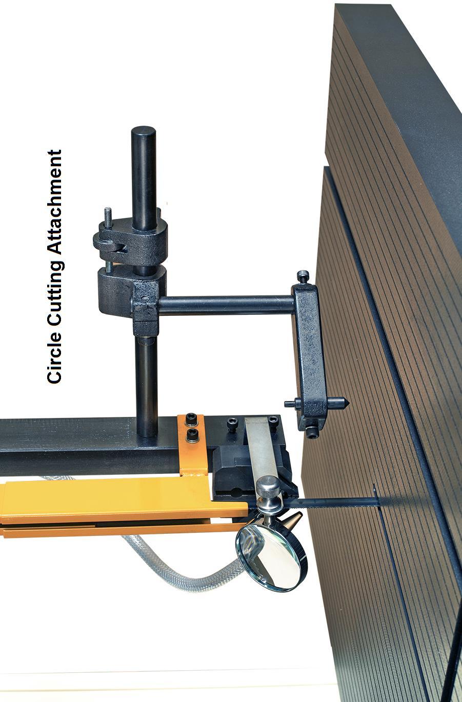
2 DAKE V-26E TABLE OF CONTENTS Forward Installation and set up Specifications Operational Controls Auto-Feed Table Operation: Blade installation Blade Tracking Guide Post Adjustment Guide Adjustment / Holder and Guide Blade Selection / Type of Blades Tooth Shapes Set Types Blade Selection Chart Saw Speed & Pitch Selector Welder Operation Blade Cutting / Tooth Spacing Welding of the Blade Annealing (Carbon) Annealing (Bi-Metal) Blade Dressing (Grinding) Weld Inspection Blade Weld Trouble Shooting Trouble Shooting Chart / Saw /Blade / Cutting Maintenance Exploded Diagrams and Parts Lists Electrical Drawing Warning / Safety Labels Circle Cutting Attachment Installation and Set Up
3 FOREWARD First of all, we would like to take this opportunity to thank you for selecting our Dake V-26 E model vertical Bandsaw. As you know, the vertical bandsaw is a universal saw for contour cutting. Blade selection is important and by choosing the right blade, you can make most any pattern cutting on most any material with this machine. However, the most important thing is to realize how to operate it in a safe and correct way and how to maintain it. We have tried to supply you all the information about these. Please be sure to look through all the contents in this manual so that you may obtain the maximum efficiency and the longest machine life with minimum expense. The specifications and information in this manual were current at the time this manual was approved for printing. Dake, whose policy is one of continuous improvement, reserves the right, however, to change specifications or design at any time without incurring obligations. Always include the part number, model number, and parts description, for parts orders or correspondence concerning your bandsaw, so we can supply you a rapidly after-sales service. WARNING 1. Read the operator s manual carefully. Learn the tools applications and limitations, as well as the specific potential hazards peculiar to it. 2. Always wear approved safety glasses/face shields while using this machine. 3. Make certain the machine is properly grounded. 4. Before operating the machine, remove tie, rings, watches, other jewelry, and roll up sleeves above the elbows. Remove all loose clothing and confine long hair. DO NOT wear gloves when operating. 5. Keep the floor around the machine clean and free of scrap material, oil and grease. 6. Keep machine guards in place at all times when the machine is in use. If removed for maintenance purposes, use extreme caution and replace the guards immediately. 7. DO NOT over reach. Maintain a balanced stance at all times so that you do not fall or lean against blades or other moving parts. 8. Use only sharp blades. Dull blades are dangerous. 9. Make all machine adjustments or maintenance with the machine unplugged from the power source. 10. Use the right tool. Don t force a tool or attachment to do a job which it was not designed for
4 11. DO NOT make cuts requiring more power than is available on the machine. 12. Replace warning labels if they become obscured or removed. 13. Make certain the motor switch is in the OFF position before connecting the machine to power. 14. Give your work undivided attention. Looking around, carrying on a conversation. And horse-play is careless acts that can result in serious injury. 15. Make a habit of checking to see that keys and adjusting wrenches are removed before turning on the machine. 16. Keep visitors a safe distance from the work area. 17. Use recommended accessories; improper accessories may be hazardous. 18. Never place hands directly in line with the saw blade. 19. Always use push sticks when cutting small material. 20. Raise or lower the blade guide only when the machine has been turned off and the blade has stopped moving. 21. Read and understand warnings posted on the machine. 22. DO NOT use attachments for any other purpose than for what they were designed for. 23. Failure to comply with all of these warnings could lead to serious injury. INSTALLATION WARNING!!! The machine table must NOT be used as a lifting point. Damage to the saw could occur. UNLOADING: Remove the shrink-wrap covering the machine, careful not to damage painted surfaces. Carefully inspect the machine for physical damage. If damage is noted, notify the truck line at once. They may require inspection, and that a claim be filed. Check that all standard accessories are with the machine. Some accessories may be boxed or placed behind the rear access door. The band saw is provided with a lifting eye that is screwed into the top of the machine. This lifting eye may be located in the rear compartment. Particular care should be taken in selecting areas of the machine for handling, as electrical components and adjustment knobs can be marked up or damaged. Remove the mounting bolts holding the machine to the skid, using the lifting eye, remove the machine from the skid and set in designated area
5 CLEANING 1. Remove anti-rust oil. 2. Remove the coating with a clean brush applied with appropriate solvent. 3. When the coating has been softened, remove it with clean rag. POWER SUPPLY 1. Shut off the main power switch before connecting cable. 2. Check motor voltage against supply voltage. 3. Make sure the power supply is connected to comply with the local safety regulations. 4. Your saw may be pre-wired with a power cable attached. This cable can be hard wired or the preferred method of installing a properly rated quick disconnect. WARNING All electrical connections must be done by a qualified electrician. Failure to comply may cause serious injury! All adjustment or repairs must be done with the machine disconnected from the power source. Failure to comply may result in serious injury! 5. The leads connect to L1, L2, and L3 and ground. The bandsaw must be grounded. 6. Check that the blade is running in the correct clockwise direction. If the blade runs backwards, disconnect the power. Then reverse any two of the three L1, L2, and L3 leads. Do not reverse the ground. SPECIFICATIONS Capacity 26 X 13 Blade Width Cap. 1/8 ~ 1 Blade Speed 50-5,000 fpm Table Size 23.5" x 27.5" Table Travel 12 Table Force Table Speed (No Load) 80 kgcm max. Forward 12 in 28 seconds, Reverse 12 in 24 seconds Table Tilt R-45, L-10 Main Drive Motor Grinder Motor 230 volt 3 Phase, 3 HP 110V, 1 Phase, 0.04 KW Blade Length 184 Blade Welder Cap 4.2 KVA, 1/8 ~ 3/4 Band Wheel Diameter 26 Table Height 39 Dimension Mach. Weight 52 3/4 (Length) 31 (Width) 86 (Height) 1,377lbs
6 1 Control Panel 8 Guide Post Lifting Wheel 2 Blade Shear 9 Guide Post Locking Knob 3 Welder Panel 10 Work Lamp 4 Grinding Wheel Motor 11 Blade Guide Holder 5 Variable Speed Handwheel 12 Work Table 6 Lifting Eye 13 Table Support Housing 7 Upper Wheel 14/15 Low / High Range Lever, Lower Wheel - 5 -
7 CONTROLS Low/High Range Shift Lever Located on right side of machine base. Pull toward the front of the machine to shift into the low speed range. Push toward the rear of the machine to shift into the high-speed range. Caution: Do not change the speed range while the machine is running. Adjust only when the machine is stopped NOTE: If the lever will not mesh the speed range, slightly rotate the band wheel and the lever will go into gear. Variable Speed Hand Wheel Located below the worktable on right side of machine base. Turn clockwise to increase speed and counter-clockwise to decrease speed. Caution: Do not turn handle while machine is stopped. Adjust speed only when machine is running. RPMs will be displayed on the control panels digital readout. Upper Guide Post Lock Knob Located on right side of upper frame. Turn counter-clockwise to loosen and clockwise to tighten. Always support the guide post when adjusting this knob to prevent unexpected dropping of the guide post. Work Lamp Switch Turn lamp on and off. Caution must be used as light will be hot. Blade Shear Lever Located on upper left hand side of the column. Lever up position allows insertion of the blade into the shear. Pull lever downward to cut the blade. (This shear unit must be mounted during set up) Grinder Toggle Switch Located on the blade welder panel found on columns front. Flip switch up to start grinder; flip down to stop grinder. This motor has temperature protection which will turn off the power automatically when the motor is over-hearting. Motor will reset once it cools down. Weld Button Located on the blade welders panel found on the front of the column. Depress and hold to start welding. Shuts off automatically when weld is done. Release when weld is completed Anneal Button Located on the blade welders panel found on the front of the column. Depress and hold to anneal blade, release to stop. Blade Clamp Pressure Knob Located on the blade welders panel found on front of the column. Sets pressure for different width blades. Blade Clamps Located on the blade welder panel found on the front of the column. Down position allows insertion of the blade into the clamp. Up position locks blade Blade Tension Hand Wheel Located on underside of the upper frame. Turn clockwise to tension the blade; counter-clockwise to release tension on the blade. Blade Tracking Hand Wheel Located at the upper rear of the saw. Turn clockwise to track the blade toward front of the blade wheel Turn counter-clockwise to track blade toward rear of the blade wheel. (Do not let the blade ride up onto the wheel lip) Table Tilt Mechanism Located under worktable. To tilt table left or right, loosen hex cap - 6 -

8 screws at the rear of the mechanism. Always tighten table bolts before operating the saw Control Panel: 1. Digital Readout- Located on control panel. Shows blade speed in feet per minute. Note: When starting up or changing speed, allow time for the readout to stabilize to the new setting. 2. Automatic Cutting Switch Press this button to make the table travel forward and reverse automatically. 3. Table Manual Forward Switch Press this button to make the table travel forward, release to stop. 4. Table Manual Reverse Switch Press this button to make table travel reverse, release to stop 5. Continue Cutting Select Switch Turn ON this button to make continuous cuts. 6. Table Feed Pressure Selector Adjust the feed pressure. Rotate from 9 o clock position (minimum) to 3 o clock position (maximum). 7. Power indicator Light Indicates that power to the control panel is on. 8. Main Motor Start Switch Depress to start bandsaw 9. Main Motor Stop Switch Depress to stop bandsaw. 10. Automatic Stop Select Switch Turn ON this button while cutting work piece. machine will stop automatically after the cut is finished. Turn OFF this button after finishing to return to normal work

9 11. Key Lock Switch Turn the key to the 12 o clock position and remove key to lock out power from the control panel. 12. Emergency Stop Switch Press to stop the machine. Turn knob 90 to reset. MANUAL CUTTING, TABLE STATIONARY 1. Adjust table all the way forward 2. Make sure Auto-stop is off. 3. Depress the motor start button 4. Adjust your blade speed. 5. Begin free hand cutting. AUTOMATIC CUTTING Please make sure that the Auto Stop switch is in the OFF position before making this adjustment. 1. Turn pressure selector knob all the way to the maximum. (3 o clock setting) 2. Depress manual forward and reverse buttons to make table travel. Adjust limits as follows. 3. Adjust the forward limit switch to the position (B) where you want the cut to stop. Adjust knob to just trip the limit switch. 4. Adjust the reverse limit switch to the position (A) where you want the cut to start. Adjust knob to just trip limit switch. 5. Adjust table to the start position, load material, set pressure selector knob to the minimum (9 o clock) position that forces the table travel to start at a slow rate 6. Depress machine start switch. (Adjust blade speed if needed) Using the manual reverse switch run the blade up to the material. 7. Depress automatic button, to make the table travel and slowly start cutting the work piece. Adjust to proper cutting pressure. Adjust pressure selecting knob to the position where the work is being cut safely and efficiently. 8. At the end of the cut the blade will keep running and back itself out of the cut. Shut the blade off with main motor off button. 9. To stop the blade at the end of cut switch Auto Stop switch on when the cut starts. Remove piece and turn off Auto Stop. Blade and table movement will shut off at the end of the cut. CONTINUOUS CUTTING Set up stops as mentioned above. Depress continuous cutting switch, this will provide a - 8 -
10 continuously cutting cycle for light material. SINGLE PIECE CUTTING Switch on automatic stop selector knob when the saw is cutting. Machine will stop automatically after the cut is finished. NOTE Depress manual-reverse button to back the work piece from the blade if there is any damage or binding to the blade while cutting, or when table travel set up needs adjusting. However, be sure to adjust feeding pressure lower when reversing out of a cut, to resume the cut the work piece cut should be close to the blade before you start to feed the table again. Do not start blade if the teeth are in contact with the material. Table Feed Pressure Selector is just to adjust the pressure of table feed, not for the feeding speed. OPERATIONS BLADE INSTALLATION 1. Install the blade as illustrated through the guides and onto the upper and lower wheels. Replace any guarding that was removed after blade is installed. 2. Adjust blade tension per the tension scale by turning the blade tension adjustment hand wheel. The scale is visible from the rear side. 3. Jog the machine to see if the blade tracks properly, adjust blade tracking by turning the tracking adjuster when it is necessary. (See blade tracking section on next page for further details) Proper tensioning Improper tensioning - 9 -

11 BLADE TRACKING Blade tracking may be required from time to time depending on the blade size and tension. Disconnect the machine from the power source and open both blade wheel doors. Shift the high-low gearbox lever into the neutral position. Turn the upper blade wheel by hand while observing blade position on the upper blade wheel to determine if adjustment is necessary: a. Turn blade tracking knob clockwise to track blade toward front of blade wheel. b. Turn counter-clockwise to track blade toward rear of blade wheel. Blade should be tracked as close of the center of the top blade wheel as possible. Do not allow blade to run on the wheel lip. Note: Upper and lower blade guides should be moved away and left loose from the blade while tracking adjustments are being made. GUIDE POST ADJUSTING 1. Loosen the guide post locking knob. Always support the guide post when loosening the guide post to prevent it from unexpectedly falling. (Figure A next page) 2. The height of the upper guide post setting is in relationship to the height of the material. The height between the material and the blade guide end is suggested to be about 1/4. (See figure B illustration on next page) 3. Lock the guide post tightly. WARNING All adjustment or repairs to the machine must be done with the power off and the machine disconnected from the power source. Failure to comply may result in serious injury!
12 Figure A Figure B It may be necessary to open the blade guides, before you adjust the guide post to allow free movement of the guide post. GUIDE HOLDER ADJUSTMENT 1. Loosen the inner hex screws located at the right lower side of guide post with an L shaped allen wrench. 2. Adjust the guide holder forward or backward according to the blade width. The front edge of the blade guides must be adjusted about 1/8 behind the blade teeth. (see figure B next page) 3. Tighten the screws securely. BLADE GUIDE ADJUSTING 1. Loosen the inner hex screws of the blade guide with an L shaped allen wrench. 2. Adjust the blade guides very close to the blade but not touching the guide faces. (approx. thickness of a business card) 3. With blade tight allow guides to ride up to the blade not forcing them off center. Tighten the blade guides securely. (See figure A next page) NOTE: There are a total of four blade guides and two guide holders located above the table and under the table, all to be adjusted to the same position


13 Figure A The blade guides will wear after time at the front faces. If the blade guides become hard to be properly adjusted, turn the left blade guide over to the right side, as illustrated in the right illustration, and turn the right-side blade guide over to the left side as well. The blade guides can then be used on both sides getting more mileage out of the guides. Figure B The backup blade guide button will wear over time as friction from the saw blade may cause a worn line on its surface. If this is found to happen, loosen the lower guide holder bolt and turn it to rotate the button shaft to change the buttons position on the saw blade. CAUTION Blade guide must be properly adjusted or damage may occur to the blade and/or the guides. BLADE SELECTION To get the most satisfactory work from your saw, it is important to choose a blade that is correct for the work. Blade life, cut straightness, finishing quality and sawing efficiency is all related to the choice of blade. Blade breakage, teeth stripping, crooked cuts, and other common complaints are, in most instances, caused by using the wrong blades. Blades are classified by materials, tooth shapes, and types of set
14 TYPES OF BLADES Bandsaw blades are available in specific sizes, or in 100 feet coils. They are made from several different metals: 1. Carbon Steel Blade: which are widely used because of their general adaptability for all types of work and the low cost. They are excellent for cutting nonferrous metals and plastics. 2. High-Speed Steel Blade: which resist heat generated in cutting to far greater extent than carbon steel blades. They are best suited for cutting ferrous metals. 3. Alloy Steel Blade: which are tougher and more wear resistant than either of the above. They will cut faster and longer than blades of carbon or high-speed steel. 4. Carbide-Tipped Blade: which are best used for cutting unusual materials such as uranium, titanium, and beryllium. These metals are difficult to cut with other types of blades. TOOTH SHAPES The regular or standard tooth is preferred for all ferrous metals and general-purpose cutting. The skip-tooth blade has widely spaced teeth to provide the added chip clearance needed for cutting softer nonferrous materials. The hook, or saber tooth blades has a 10 undercut which permits better feed and chip removal, it is best for the harder nonferrous alloys. SET TYPES Regular or rake set is generally furnished on saws that have 2 to 24 teeth per inch. These blades have one tooth set to left, one to right, and one unset tooth called a rake. This set is used when material is to be contour cut. Wavy set is furnished on saws that have 8 to 32 teeth per inch. This set has groups of teeth bent alternately to left and right, which greatly reduce the strain on individual teeth. Saws with wavy set are used where tooth breakage is a problem, such as in cutting thin stock or where a variety of work is cut without changing blades. Of the three common set patterns, only raker and wave are now used in metalworking. Always use rake set except: For work of varying cross section use wave set. When one blade must be used for a range of material sizes use wave set
15 PLEASE NOTE THAT CORRECT BLADE SELECTION IS VERY IMPORTANT TO BANDSAW OPERATING AT FULL POTENTIAL. ALWAYS SELECT A BLADE ACCORDING TO THE MATERIAL SHAPE AND THICKNESS OF THE WORK Always break in the blade per blade manufactures recommendations. SAW BLADE SELECTION MATERIAL SHAPE MATERIAL SHAPE MATERIAL SHAPE MATERIAL IN INCHES TOOTH SELECTION TOOTH SELECTION TOOTH SELECTION 0 14 / / / / / / / / / / / / / / 14 8 / / 12 8 / 12 6 / / 10 8 / 12 5 / / 10 6 / 10 5 / / 8 6 / 10 5 / / 8 5 / 8 5 / / 8 5 / 8 4 / 6 1 1/4 4 / 6 5 / 8 4 / 6 1 1/2 4 / 6 4 / 6 4 / 6 1 3/4 4 / 6 4 / 6 4 / / 6 4 / 6 3 / 4 2 1/4 4 / 6 4 / 6 3 / 4 2 1/2 3 / 4 4 / 6 3 / 4 2 3/4 3 / 4 4 / 6 3 / / 4 3 / 4 3 / 4 3 1/4 3 / 4 3 / 4 3 / 4 3 1/2 3 / 4 3 / 4 3 / 4 3 3/4 3 / 4 3 / 4 2 / / 4 3 / 4 2 / / 3 3 / 4 2 / / 3 3 / 4 2 / / 3 2 / / / / / / / / / / / / / / / / /

16 Please refer to the Speed & Pitch Selector wheel that is supplied on your saw for speeds and feeds, radius cutting and blade pitch selection. Select saw blades in relationship to the thickness of materials. The following suggestions are a rule of thumb to consider when selecting a blade. A. Select a larger pitch blade for a thicker material. B. Select a smaller pitch blade for a thinner material. C. Use a smaller pitch blade to obtain a smooth cutting surface. D. Use a larger pitch blade to obtain a faster cutting speed. E. It is important to have different blades for different applications

17 WELDER OPERATION This welder is for occasional use for blade repair and is not intended for welding blades on a regular basis from bulk stock. This welder is best suited for carbon bands but with practice both carbon and bi-metal can also be welded. BLADE CUTTING 1. Cut the blade to the length of the machine. Using the blade shear will insure that the blade ends are cut flat, square and smooth. 2. Place the back edge of blade against the square cutting guide of the shear and firmly pull the cutting lever down to shear the blade. Both ends of the blade must be sheared to allow for a good butt weld. 3. Keep the shear blade clean and free from blade end pieces that can get trapped in the shear. Using the Blade Shear. TOOTH SPACING 1. On fine-pitched blades, one or more teeth on each side of the cut must be removed by grinding so that the cross section of the weld area of the blade is uniform. Following these guidelines will help make the teeth uniformly spaced after the weld

18 CAUTION: If the saw blade is rusty, the rust must be ground off before the blade is welded. WELDING 1. Turn pressure knob to 0 position. 2. Butt blade ends together and locate joint in the center between the two electrodes. 3. Set pressure knob to blade width. (Due to the different materials and thickness of blade, please pay especial attention to the pressure adjustment. Thicker the blade higher the pressure setting.) 4. Press and hold welder button. Do not release until the blade joint is red hot. The switch is automatic and will shut welder off after a preset time of 3 or 4 seconds and the blade returns to original color. Note: The weld joint may throw sparks during welding so wear safety glasses and proper apparel. ANNEALING (Carbon Blades) 1. Turn pressure knob to 0 position. 2. Release blade and center the weld joint at the front of the electrodes. (At the wider part) 3. Press and jog the annealing switch button until the weld is a dull cherry to cherry red color. Allow the blades to cool slowly by decreasing the jogging frequency. 4. Perform the annealing operations 4 or 5 times, gradually reducing the heat each time. 5. Remove any welding dust or scale from the joint and anneal 2 or 3 more times, successively at lower temperatures. (quicker series of press and release of annealing button)
19 ANNEALING (Bi-Metal) Set up blade for annealing as mentioned above for carbon blades steps 1 & 2. Heat the band slowly by jogging the annealing switch button until the weld just begins to emit light (this would be the dullest red color) or minute puff of smoke. The desired color may not be visible in normal room light. Always shade the weld area with your hand. Cool the weld quickly by releasing the annealing button. Repeat this operation 4 or 5 times. NOTE: This procedure should be followed both before and after grinding BI-METAL Blades. GRINDING THE WELDED BLADE WARNING Keep hands away from rotating grinding wheel. When not in use make, sure wheel is covered with built in cover After welding, the blade must be dressed to remove excess metal or flash from the weld. Grind the welded area down to the same thickness as the rest of the band. Handle the blade carefully. Grind Carefully: do not hit the teeth; or grind deeper than the thickness of the blade; or overheat the weld area. Be sure to remove flash from the back edge of the blade. Any flash or stub teeth that project beyond the normal set or height of the other teeth must be ground off. Anneal the welded area that was ground again. Anneal 2 or 3 times using a lower temperature. (Just as area starts to emit light)

20 INSPECION OF THE WELD When the blade is removed from the welder it should be inspected carefully. The spacing of the teeth should be uniform and the weld should be located in the center of the gullet. Major jaw misalignment is easily noted at this time from the weld appearance. See the trouble shooting chapter if the weld is imperfect. CAUTION: This welder is designed for intermittent use. Repeated welding within a short period of time may cause the welder to overheat. TROUBLE SHOOTING MISALIGNED WELD (1) Dirt or scale on jaws or blade. (2) Blade ends not cut off square. (3) Blade ends not correctly aligned when clamped in jaws. (4) Worn jaws or inserts. (5) Jaws are not aligned correctly
21 MISALIGNED WELD-BLADE ENDS ARE OVERLAPPED (1) Jaw Upset Force Control set for wider blade than used, re-adjust correctly. (2) Blade ends or jaws not aligned correctly. WELD BREAKS WHEN USED (Joint is not complete, blow holes in joint) (1) Weld not annealed correctly. (2) Weld has been ground too thin. (3) Weak Incomplete weld. INCOMPLETE WELD (Items 3 8 requires welder removal) (1) Incorrect Initial Set-Up: (a) Initial jaw gap (weld lever position) not set correctly. (b) Upset force control not set correctly. (2) Improper clamping procedures. (3) Defective cut-off switch may not break the circuit at end of welding operation. (4) Cut-off Switch not adjusted correctly. (5) Points of cut-off switch welded together. (6) Slide Rod sticking because of rust or dirt. Clean and oil the rod. (7) Slide Rod movement obstructed because the stop screw too tight on the Rod. (8) Jaw movement obstructed by kinked jaw cable or tangled wires. Bend cable and untangle wires. BRITTLE WELDS Weld has not been annealed correctly; see Annealing in operation chapter. Poor annealing can be caused by: 1. Incorrect annealing heat. Bring weld up to correct color as described under Annealing in welder operations chapter. 2. Scale or oil on weld can cause poor annealing. TROUBLE SHOOTING PROBLEM CAUSE SOLUTIONS The Weld could not be made, the Jaws do not move The weld area melts the blade not welds it when welding switch is pushed A. The wire connection is poor, the connecting point of welding switch is bad B. The transformer is burnt out C. Some oil is on the blade D. Some rust is on the blade ends E. The adjustment of the welding pressure is incorrect A. The welding switch cut off too late B. The Welding Pressure is too weak C. The jaw movement is too slow A. Change the welding switch. B. Change the transformer. C. Remove the oil D. Grind off the rust E. Loosen the adjusting screw that is in center of it A. Screw the welding switch Connecting Nut tight B. Turn the welding pressure adjuster clockwise C. Put some oil on the rear side of the welding lever jaws
22 The annealing job cannot be made when pushing the anneal button A. The connection of annealing switch is loose or broken B. The fuse is blown C. The connection of the electrodes to blade is poor A. Change an anneal switch B. Change a fuse C. Clean electrode surfaces The grinder is not running when the grinder switch on A. The grinder motor is defective B. The grinder switch is defective A. Replace the grinder B. Replace the switch The blade can not be tightly clamped with the jaw clamps A. The jaw clamps are burnt or defective B. The lower jaw inserts defective C. The Jaws are burnt or eroded A. Change clampers B. Change lower jaw Inserts C. Change jaws The annealing button will not release to neutral position Blade tooth broken Some dust or debris around the anneal button restricting movement A. Incorrect pitch for the application B. Brittle blade improper annealing C. Inferior blade Release the anneal button by gently pulling it to the neutral position Clean out any dust or debris A. Select a right pitch blade B. Re-weld and anneal C. Decrease feeding rate D. Change to high quality blade Blade damaged A. Brittle blade improper annealing B. Blade tension out of adjustment C. Too Fast feeding D. Blade teeth hitting guides. E. Cannot cut radius without blade twisting. A. Decrease the annealing temperature B. Adjust blade tension C. Decrease feed rate D. Adjust a proper gap between the blade and the guide insert E. Change to a narrower blade PROBLEM CAUSE SOLUTIONS Saw blade is twisted A. Improper weld B. Blade installed in improper way C. Blade tension too loose D. The blade is being over fed A. Re-weld the blade again B. Set the guide inserts closer C. Increase blade tension D. Decrease the feeding rate when starting the cut E. Use a proper width blade for radius cutting The sawing direction deviates A. The blade tooth is not on even or warn unevenly. B. The blade tension is too loose C. The guide post was set too high A. Make sure a good blade is used without damaged teeth B. Increase blade tension C. Set the guide post to be within a ¼ of the work D. Decrease feeding rate Saw blade walks off A. Blade tension is too loose B. Blade is not tracked properly A. Increase blade tension B. Adjust the wheel alignment
23 The blade dulling prematurely A. The blade speed is too fast B. The selection of blade is improper C. Feeding rate too fast A. Slow down the blade speed B. Use a proper blade for the application C. Decrease feeding rate The blade is not cutting straight vertically A. The blade dull B. The guide post is not properly fixed C. The blade tension is too loose D. The blade is not exactly 90 to the table A. Change to a new blade B. Fix the guide post properly ¼ above material C. Increase blade tension D. Adjust it to be 90 Excessive noise when machine is running A. The variable speed pulley is damaged C. The saw is not sitting flat on the floor A. Change a new pulley B. Reposition the machine on a flat even hard floor MAINTENANCE PART OR PLACE TO BE TYPE OF OIL LUBRICATING REMARKS OILDED OR GREASED OR GREASE PERIOD Bearings Gear oil every 6 months Gear Box: Guide post sliding part Grease weekly #1350 & #1360 Speed Change handle Grease every 6 months #0600,# 0740, #7120 & #7290 Gear and thread Grease every 3 months #7080 & 7110 Variable pulley Grease N/A #9995: V-16 only Table slide shaft Machine oil daily #1250: E-type only Upper wheel slide block Machine oil monthly #3100 & #3110 Blade Tension Screw Grease monthly #3110 & #3120 Welder Jaw (clean up daily) Rubber Tire (clean up daily) Work Table Assembly (clean up daily)
24 - -
25 GEAR BOX COMPONENT GUIDE POST COMPONENT * GEAR BOX GUIDE SUPPORT, UPPER * GEAR BOX COVER GUIDE SUPPORT, LOWER * GEAR BLADE GUIDE * GEAR BLADE STOPPER, LONG * SCREW NUT BLADE STOPPER, SHORT * SCREW NUT ECCENTRIC SHAFT * GEAR BLADE GUIDE POST * GEAR SHAFT GEAR BAR * SHAFT COVER GUIDE POST HOUSING * GEAR BLADE GUARD, LEFT * MAIN SHAFT BLADE GUARD, RIGHT * MAIN SHAFT COVER SPRING * SPEED CHANGING SHAFT SPRING HOUSING * SPEED CHANGING ARM POST HOUSING SPRING * SHAFT STOPPER POST ELEVATING GEAR * SPRING CIRCLE CUTTING ATTACHMENT * SLIDE BLOCK GUIDE POST LOCK * CLUTCH POST ELEVATE HANDWHEEL * BRASS BRACKET HANDLE KNOB * BRASS BRACKET G BALL BEARING G * BALL BEARING G * BALL BEARING G * BALL BEARING MAIN DRIVE G * BALL BEARING L * OIL SEAL MAIN DRIVE MOTOR L * OIL SEAL MOTOR PULLEY L * OIL SEAL MOTOR ROTARY SEAT CP GEAR BOX COMPLETE BA43 2 V-BELT, SPEED CHANGING LEVER BA60 1 V-BELT, SHAFT HOUSING SPEED LEVER RIGHT PULLEY WHEEL COMPONENT LEVER KNOB * LOWER WHEEL BA44 2 V-BELT, (60HZ) * RUBBER TIRE BA45 2 V-BELT, (50HZ) CP LOWER WHEEL COMPLETE TAPER SLEEVE WHEEL LOCKING NUT WORK TABLE COMPONENT * RUBBER TIRE * UPPER WHEEL WORK TABLE G * BALL BEARING TABLE SUPPORT FRAME CP UPPER WHEEL COMPLETE BLADE GUARD UPPER WHEEL LOCK
26 WHEEL COMPONENT CONT. WORK TABLE CONT * SLIDE BLOCK HOUSING TABLE SUPPORT HOUSING * SLIDE BLOCK SEAT GUIDE SUPPORT HOUSING * SLIDE BLOCK GUIDE RIGHT-HANDED SCREW 3110A 1 * UPPER WHEEL SLIDER LEFT-HANDED SCREW * SLIDER SCREW SHAFT SLIDER * WHEEL ELEVATE SHAFT TABLE TILT ADJUST SCREW * SPRING BEARING COVER * WASHER TABLE STROKING SHAFT * INDICATOR RING METER GAUGE CP SLIDE HOUSING COMPLETE RIP FENCE + LOCK TENSION INDICATOR T-BLOCK WHEEL TILT ADJUSTER RIP FENCE SLIDE GUIDE WHEEL TILT CONNECTER TORQUE MOTOR CONNECTER WASHER TORQUE MOTOR SPEED CONNECTER HOUSING REDUCER WHEEL GEAR HANDWHEEL SLIDE GEAR TILT ADJUST HANDWHEEL TORQUE MOTOR HOUSING SET RING SLIDE BAR LIMITED SWITCH SET RING LIMITED SWITCH HOUSING LIMITED SWITCH SET RING LOCK GLM35 4 LINER BEARING AIR PUMP COMPONENT VARIATOR COMPONENT AIR PUMP SEAT MOTOR SPRING HOUSING AIR NOZZLE * SPRING AIR NOZZLE CLIPPER * VAEIATOR DISK, UPPER AIR COMPRESSOR * VAEIATOR DISK, UPPER BA60 1 V-BELT, * VARIATOR HOUSING TUBE * VARIATOR SHAFT * VARIATOR HOUSING G * BALL BEARING G * BALL BEARING CP VARIATOR HOUSING MAIN BODY & MISCELLANCEOUS PULLEY WORM GEAR MAIN BODY WORM GEAR HOUSING REAR DOOR, LARGER GEAR SHAFT REAR DOOR, SMALLER WORM LOWER DOOR WHIRLING ARM UPPER DOOR * SPRING HOUSING CONTROL PLATE * SPRING
27 VARIATOR INSTRUCTION * VARIATOR DISK, LOWER GEAR BOX INSTRUCTION 7230A 1 * VARIATOR DISK, LOWER INDICATOR PLATE * SHAFT HOUSING TILT INSTRUCTION G * BALL BEARING UPPER DOOR HINGE G * BALL BEARING HINGE CP SHAFT HOUSING COMPLETE SPRING PLATE SPEED CHANGE WHEEL SEAT HANDLE ARM PULLEY CHIP STOPPER SPEED READOUT DETECTOR INDICATE MIDDLE DIGITAL TACHOMETER BRUSHER BRACKET HANDWHEEL CHIP BRUSHER BA44 - V-BELT, (60HZ) KEY FOR REAR DOOR BA45 - V-BELT, (50HZ) CHIP COLLECTOR BA43 - V-BELT, EYE BOLT BV875 1 V-BELT CONTROL SWITCH COMPONENT VARIABLE TRANSFORMER PUSH BUTTON, ON, GREEN PUSH BUTTON, ON, WHITE PUSH BUTTON, OFF, RED PUSH BUTTON, ON/OFF, BLACK EMERGENCY SWITCH DOOR LIMIT SWITCH KEY SWITCH SELECT SWITCH MAIN POWER SWITCH MAGNETIC SWITCH OVERLOAD STARTER CONDENSER PILOT LAMP, GREEN VOLTAGE REDUCER FUSE SEAT FUSE SEAT FUSE SEAT POWER RELAY WIRE HOUSING GROUND SEAT WIRE HOUSING ELECTRIC BOX WIRING PLATE

28
29 WELDER COMPONENT WORK LAMP COMPONENT * LIMIT SWITCH * INSULATOR * GUIDE BLOCK * HOUSING * WORK LAMP COMPONENT Bulb MR 16 12v 20W * STATIONARY JAW SHEAR COMPONENT * INSULATOR * INSULATING TUBE * SPINDLE BUSHING * WASHER, INSULATE * SPINDLE LIFT * SPACER * BLADE SHAFT * ECCENTRIC SHAFT * VANED IRON PLATE * CLAMP LEVER, RIGHT * LOWER BLADE * CLAMP LEVER, LEFT * UPPER BLADE * CLAMP SUPPORT, RIGHT * JOINT PLATE, LEFT * CLAMP SUPPORT, LEFT * CHAIN JOINT, RIGHT * CLAMP PLATE, RIGHT * HANDLE BAR * CLAMP PLATE, LEFT * KNOB * CLAMP PLATE, LEFT SCP 1 SHEAR COMPLETE * CAM * MOVING JAW * WELD BUTTON * MICRO SWITCH * MICRO SWITCH BRACKET * PRESSURE ADJUST KNOB * SHAFT * CAM * WELD TENSION ARM * BUSHING * SPRING, SHORTER * SPRING, LONGER * TRANSFORMER (4.2KVA) * MOUNTING BRACKET (4.2KVA ONLY) * SWITCH * GRINDER MOTOR * SPACER * GRINDER WHEEL * 1/4 WASHER, FLAT * 6 mm-1.0 HEX NUT * GRINDER GUARD * GRINDER COVER * WELDER NAME PLATE * INSTRUCTION LABEL * GRINDER LABEL * ANNEAL BUTTON * DEFLECTOR BRACKET, RIGHT * DEFLECTOR BRACKET, LEFT * SPARK DEFLECTOR * KNOB WCP 1 42-WELDER ASSEMBLY Electric appliance arrangement diagram
30 -
31


32 Warnings Employer is responsible to perform a hazard/ppe assessment before work activity. Do not make repairs or adjustments unless you are competent or working under competent supervision. If in doubt consult a qualified technician or engineer Only use Dake original parts Do not alter this band saw from the original design. Lock out Tag out procedures must be followed by authorized employees as per OSHA. ELECTRIC Electric must be locked out in accordance to OSHA standards. WARNING LABELS To the left is the safety Alert symbol. When you see these safety alert symbols on your band saw, be alert to the potential for personal injury. Follow recommended precautions and safe operating practices. Carefully read all safety messages in these instructions and on your band saw safety signs. Keep safety labels in good condition. Replace missing or damaged safety labels. This machine is intended to be operated by one person.
33

34
DAKE VERTICAL BAND SAW
 DAKE VERTICAL BAND SAW Model V-16 INSTRUCTION MANUAL Please record your saws information DAKE (Division of JSJ) 724 Robbins Road Grand Haven, Michigan 49417 616.842.7110 Phone 800-937-3253 616.842.0859
Parts List: VBS-3612 Band Saw
 Parts List: VBS-3612 Band Saw (refer to breakdowns on pages 35 and 36) Index No. Part No. Description Size Qty 1... VBS3612-101...Gear Box... 1 2... TS-0209101...Socket Head Cap Screw...3/8-16 x 2-1/4...
Horizontal and Vertical. Metal Cutting Band Saw MODEL: BS-115
 Horizontal and Vertical Metal Cutting Band Saw MODEL: BS-5 SAFETY. Know your band saw. Read the operator s Manual carefully. Learn the operations, applications and limitation.. Use recommended accessories.
Mini Max 20 BAND SAW
 OPERATING PROCEDURE FOR: Mini Max 20 BAND SAW SAFETY RULES: Warning: Willful violations of these safety rules, disruptive actions or horseplay may result in loss of the privilege to use the tools and machinery
VARIABLE SPEED WOOD LATHE
 MODEL MC1100B VARIABLE SPEED WOOD LATHE INSTRUCTION MANUAL Please read and fully understand the instructions in this manual before operation. Keep this manual safe for future reference. Version: 2015.02.02
MI MI OPERATING MANUAL
 MODEL NO.: MI-76100 MI-76150 OPERATING MANUAL RULES for SAFE OPERATION MAGNUM INDUSTRIAL MI-76100 and MI 76150 DRILL PRESSES To help ensure safe operation, please take a moment to learn the how to operate
VARIABLE SPEED WOOD LATHE. Model DB900 INSTRUCTION MANUAL
 VARIABLE SPEED WOOD LATHE Model DB900 INSTRUCTION MANUAL 1007 TABLE OF CONTENTS SECTION...PAGE Technical data.. 1 General safety rules....1-3 Specific safety rules for wood lathe.....3 Electrical information.4
18 GAUGE ELECTRIC METAL SHEAR
 241-9895 18 GAUGE ELECTRIC METAL SHEAR Operator s Manual SAVE THIS MANUAL You will need this manual for safety instructions, operating procedures and warranty. Put it and the original sales receipt in
Operating Instructions ¾ Parts Manual 27-Inch and 40-Inch Vertical Band Saws Models 8027, 8127, 8040 and 8140 Part Number
 Operating Instructions ¾ Parts Manual 27-Inch and 40-Inch Vertical Band Saws Models 8027, 8127, 8040 and 8140 Part Number 5510985 Revision A Table of Contents Cover Page... 1 General Specifications...
TB & SB Series Drill Presses
 TB & SB Series Drill Presses OWNERS MANUAL BENCH AND FLOOR DRILL PRESS TB-16 Series & SB-16-25-32-Series FOR YOUR OWN SAFETY AND OPTIMUM OPERATION READ INSTRUCTION MANUAL BEFORE OPERATING DRILL PRESS RETAIN
ELECTRIC SLIP ROLL MACHINE. Model: ESR-1300X2.5/ESR-1300X4.5 ESR-1550X3.5/ESR-1580X2.0
 ELECTRIC SLIP ROLL MACHINE Model: ESR-1300X2.5/ESR-1300X4.5 ESR-1550X3.5/ESR-1580X2.0 Operation Manual Table of contents I MAIN SPECIFICATION...2 II SAFETY INSTRUCTIONS.. 2 III OPERATION INSTRUCTIONS..4
SAVE THIS FOR FUTURE REFERENCE THIS PRODUCT IS FOR PROFESSIONAL LABORATORY USE ONLY USER'S MANUAL
 DENTAL, INC. TECHNICAL BULLETIN G801-022510 5860 FLYNN CREEK ROAD READ ALL INSTRUCTIONS P.O. BOX 106 BEFORE PROCEEDING COMPTCHE, CALIFORNIA, U.S.A. 95427-0106 SAVE THIS FOR FUTURE REFERENCE www.wellsdental.com
Operating Instructions and Parts Manual 20-inch Metalworking Band Saw Model VBS-2012
 Operating Instructions and Parts Manual 20-inch Metalworking Band Saw Model VBS-2012 JET 427 New Sanford Road LaVergne, Tennessee 37086 Part No. M-414482 Ph.: 800-274-6848 Revision H1 12/2017 www.jettools.com
 GENERAL OPERATIONAL PRECAUTIONS WARNING! When using electric tools, basic safety precautions should always be followed to reduce the risk of fire, electric shock and personal injury, including the following.
INSTRUCTION MANUAL AND PARTS LIST MODEL 14-10
 VERTICAL BAND SAWS INSTRUCTION MANUAL AND PARTS LIST MODEL 1-10 DAKE/PARMA WHEN ORDERING PARTS GIVE COMPLETE SERIAL NUMBER OF MACHINE GIVE PART NUMBER AND NAME GIVE AMOUNT REQUIRED Unless the above data
MODEL W1.0X305A(12 ) MODEL W1.0X610A(24 ) HAND BENDING BRAKE ASSEMBLY&OPERATING INSTRUCTION
 MODEL W1.0X610A(24 ) HAND BENDING BRAKE ASSEMBLY&OPERATING INSTRUCTION") MODEL W1.0X305A(12 ) MODEL W1.0X610A(24 ) HAND BENDING BRAKE ASSEMBLY&OPERATING INSTRUCTION 1 SAVE THIS MANUAL You will need the manual for the safety warning and precautions, assembly instructions, operating
MODEL W1.0X305A(12 ) MODEL W1.0X610A(24 ) HAND BENDING BRAKE ASSEMBLY&OPERATING INSTRUCTION 1 SAVE THIS MANUAL You will need the manual for the safety warning and precautions, assembly instructions, operating
SB-32V Drill Press OWNERS MANUAL
 724 Robbins Road, Grand Haven, MI 49417 Phone: 616-842-7110 800-937-3253 Fax: 616-842-0859 800-846-3253 Web: www.dakecorp.com E-mail: customerservice@dakecorp.com SB-32V Drill Press OWNERS MANUAL FOR YOUR
Agricultural Mechanics and Technology Power Tool Safety Rules
 Agricultural Mechanics and Technology Power Tool Safety Rules Name: BAND SAW Use: Cutting curves, circles and irregular shapes. 1. Use clean SHARP blades. 2. The teeth should always point DOWN. 3. Adjust
Operating Instructions and Parts Manual 16-inch Metalworking Band Saw Model VBS-1610
 Operating Instructions and Parts Manual 16-inch Metalworking Band Saw Model VBS-1610 JET 427 New Sanford Road LaVergne, Tennessee 37086 Part No. M-414485 Ph.: 800-274-6848 Revision I 01/2016 www.jettools.com
Guild of Oregon Woodworkers Shop Safety Test
 Guild of Oregon Woodworkers Shop Safety Test You must pass the Test with an 80% or better and self-correct it to 100% Make sure you put the answers under the correct portion of the answer sheet for the
EllisSaw.com. EllisSaw.com P.O. Box Verona, WI
 P.O. Box 9019 Verona, WI 9-019 GENERAL OPERATING & SAFETY INSTRUCTIONS * READ INSTRUCTIONS BEFORE USE * CAUTION: Disconnect power supply cord from power source when doing repair work or changing belt.
HOLE CUTTER SHARPENER ASSEMBLY & SERVICE MANUAL
 HOLE CUTTER SHARPENER ASSEMBLY & SERVICE MANUAL WARNING You must thoroughly read and understand this manual before operating the equipment, paying particular attention to the Warning & Safety instructions.
SALES CUSTOMER SERVICE TECHNICAL ASSISTANCE CALL TOLL-FREE:
 DENTAL, INC. TECHNICAL BULLETIN U802-022510 5860 FLYNN CREEK ROAD READ ALL INSTRUCTIONS P.O. BOX 106 BEFORE PROCEEDING COMPTCHE, CALIFORNIA, U.S.A. 95427 SAVE THIS FOR FUTURE REFERENCE THIS PRODUCT IS
Model 204B-EM Elbow Mandrels Rev TABLE OF CONTENTS
 92-0697 Rev. 970131 Model 204B-EM Elbow Mandrels TABLE OF CONTENTS CUSTOMER MESSAGE Inside Front Cover SAFETY PRECAUTIONS 3 GENERAL DESCRIPTION 6 MAINTENANCE 7 OPERATION 8 TROUBLE SHOOTING 11 ACCESSORIES
ATD AMP Variable Speed Reciprocating Saw Owner s Manual
 ATD-10535 7 AMP Variable Speed Reciprocating Saw Owner s Manual Manufactured in China To ATD Tools, Inc. Specifications TECHNICAL SPECIFICATIONS Voltage: 120V Frequency: 60Hz Power input: 7 Amps No load
Lumber Smith. Assembly Manual. If you are having problems assembling the saw and need assistance, please contact us at:
 Lumber Smith Assembly Manual If you are having problems assembling the saw and need assistance, please contact us at: 804-577-7398 info@lumbersmith.com 1 Step 1 Safety Carefully read the Owners Manual.
Introduction to Carpentry Power Tools
 Youth Explore Trades Skills Introduction to Carpentry Power Tools Description s use power tools every day, and the ability to use these tools correctly and safely is paramount. In this Activity Plan, students
Shop Fox Oscillating Spindle Sander
 OPERATING PROCEDURE FOR: Shop Fox Oscillating Spindle Sander INTRODUCTION: The oscillating spindle sander is used to sand the edges of boards. It can be used to smooth the edge or to remove material to
Tapping Screw (W/Flange) 46 Cord Armor 47 Tube (D) 48 Cord. 45 Cord Clip. Tapping Screw (W/Flange) 10 Gear Cover Ass'y. 12 Socket (B) Ass'y
 46 Cord Armor 47 Tube (D) 48 Cord. 45 Cord Clip. Tapping Screw (W/Flange) 10 Gear Cover Ass'y. 12 Socket (B) Ass'y") W8VB The exploded assembly drawing should be used only for authoized service center. W8VB Item No. Part time 1 Magnetic Hex. Socket 2 Sub Stopper 3 O-Ring (S-16) 4 Locator (A) 5 Lock Sleeve (A) 6 O-Ring
W8VB The exploded assembly drawing should be used only for authoized service center. W8VB Item No. Part time 1 Magnetic Hex. Socket 2 Sub Stopper 3 O-Ring (S-16) 4 Locator (A) 5 Lock Sleeve (A) 6 O-Ring
Powermatic Model 31A Combination Belt-Disk Sander
 OPERATING PROCEDURE FOR: Powermatic Model 31A Combination Belt-Disk Sander INTRODUCTION: The combination belt-disk sander is used to sand the edges of boards. It can be used to smooth the edge or to remove
SERVICE MANUAL AND PARTSLIST
 SERVICE MANUAL AND PARTSLIST Next 20 CONTENTS WHAT TO DO WHEN... 1~3 SERVICE ACCESS FACE COVER... 4 TOP COVER... 4 BASE COVER... 5 REAR COVER... 6 FRONT COVER... 7 MECHANICAL ADJUSTMENT NEEDLE THREAD TENSION...
Tube Facing Tool.
 www.swagelok.com Tube Facing Tool This manual contains important information for the safe and effective operation of the Swagelok TF72 series tube facing tool. Users should read and understand its contents
SPIDA SAW OPERATIONS MANUAL
 SPIDA SAW OPERATIONS MANUAL CM SERIAL NUMBER. OCTOBER 2000 CONTENTS Page description 1.) Contents 2.) Safety First 3.) CM Overview 4.) CM Specifications 5.) CM Installation 6.) CM Operation Setting the
Quick Set Dovetail Jig
 Quick Set Dovetail Jig FOR HELP OR ADVISE ON THIS PRODUCT PLEASE CALL OUR CUSTOMER SERVICE HELP LINE : 01509 500359 THE MANUFACTURER RESERVES THE RIGHT TO ALTER THE DESIGN OR SPECIFICATION TO THIS PRODUCT
3-1/4 HP VARIABLE SPEED PLUNGE ROUTER
 IMPORTANT INFORMATION 2-YEAR LIMITED WARRANTY FOR THIS PLUNGE ROUTER KING CANADA TOOLS OFFERS A 2-YEAR LIMITED WARANTY FOR NON-COMMERCIAL USE. 3-1/4 HP VARIABLE SPEED PLUNGE ROUTER PROOF OF PURCHASE Please
SERVICE MANUAL PARTS LIST MODEL: NH40
 SERVICE MANUAL & PARTS LIST MODEL: NH40 CONTENTS What to do when... 1-3 SERVICE ACCESS Face Cover... 4 Bed Cover... 5 Free-arm Cover... 6 Front Cover... 7 Rear Cover... 8 MECHANICAL ADJUSTMENT Presser
General Wood Shop Notes
 General Wood Shop Notes Restricted Materials No METAL or BONE of any kind on any machine or in the room o See additional restrictions individual machine All reclaimed and other than new lumber must be
JARVIS. Model BR-3 Blade Reconditioner ... EQUIPMENT TABLE OF
 - Model BR-3 Blade Reconditioner EQUIPMENT SELECTION.......... Ordering No. TABLE OF CONTENTS............................ Page Model BR-3 (100 mm Blade) 115V/60Hz............ 4011003 220V/50Hz............
10" Wet Tile Cutting Saw
 8035735 10" Wet Tile Cutting Saw Owner s Manual Read and understand all instructions before operation. Keep this manual for future reference pg. 2 SPECIFICATIONS ITEM DESCRIPTION Overall Dimensions (saw
GENERAL OPERATIONAL PRECAUTIONS
 GENERAL OPERATIONAL PRECAUTIONS WARNING! When using electric tools, basic safety precautions should always be followed to reduce the risk of fire, electric shock and personal injury, including the following.
Model SQM-2AC Squaring Module Rev TABLE OF CONTENTS
 92-0714 Rev. 970428 Model SQM-2AC Squaring Module TABLE OF CONTENTS CUSTOMER MESSAGE Inside Front Cover SAFETY PRECAUTIONS 3 GENERAL DESCRIPTION 6 SPECIFICATIONS 7 MAINTENANCE 8 OPERATION 9 CUTTING SPEEDS
INSTRUCTION MANUAL. Lathe Duplicator MODEL North Glenn Road, Casper, Wyoming woodworker.com
 140-069LatheDuplictr(1/12) 10/30/06 8:20 AM Page 1 INSTRUCTION MANUAL Lathe Duplicator MODEL 140-069 1108 North Glenn Road, Casper, Wyoming 82601 1-800-645-9292 woodworker.com 140-069LatheDuplictr(1/12)
Grizzly Drill Press SOP
 Grizzly Drill Press SOP Drill Press is wired to run on 0V. Drill Press has a built in light with a ON/OFF switch. Never hold a workpiece by hand while drilling. Clamp it down or hold it in a vice. Never
INSTRUCTION MANUAL AND PARTS LIST MODEL TRADEMASTER SECTION I
 VERTICAL BAND SAWS INSTRUCTION MANUAL AND PARTS LIST MODEL TRADEMASTER SECTION I DAKE/PARMA WHEN ORDERING PARTS GIVE COMPLETE SERIAL NUMBER OF MACHINE GIVE PART NUMBER AND NAME GIVE AMOUNT REQUIRED Unless
MODEL H " BYRD SHELIX CUTTERHEAD INSTRUCTIONS
 MODEL H9291 12" BYRD SHELIX CUTTERHEAD INSTRUCTIONS The Model H9291 12" Byrd Shelix cutterhead is designed to replace the straight-knife cutterhead on the Grizzly jointer Model G0609. The total procedure
Inventory (Figure 2)
") MODEL T10127 12" SPIRAL CUTTERHEAD INSTRUCTIONS The Model T10127 indexable insert spiral cutterhead is designed to replace the straightknife cutterhead from the Grizzly jointer Model G0609. The total procedure
MODEL T10127 12" SPIRAL CUTTERHEAD INSTRUCTIONS The Model T10127 indexable insert spiral cutterhead is designed to replace the straightknife cutterhead from the Grizzly jointer Model G0609. The total procedure
SAFETY AND OPERATING MANUAL
 SAFETY AND OPERATING MANUAL BladeRunner X2 WX572 9 10 8 11 5 7 12 6 20 1 2 4 3 14 13 15 A2 A1 17 18 B2 B1 1 2 1 2 19 B3 3 4 2 C 1 D1 D1 C 2 1 E1 D2 1 2 E2 1 2 F G1 G1 F OFF ON G2 G3 H1 H2 I1 I2 I1 I2 J
SERVICE MANUAL FOR HOMELOCK M1034D 2034D 1134DW 1134D
 SERVICE MANUAL FOR HOMELOCK M1034D 2034D 1134DW 1134D 11.2000 2.2012 I HOW TO USE THIS MANUAL... 1 II HOW TO ADJUST... 2 1. Height of needle bar... 2 2. Position of the lowerlooper... 3 3. Timing of the
G0513X2 Main. G0513 Series Bandsaws (Mfd. Since 07/18) A V2
 A V2") G0513X2 Main 55 17 48 7 16 55A 14 15 49 13 47 50 12 10 71 70 72 73 59 69 74 46 11 9 8 76 5 75 4 68 81 80 67 66 48 50 39 78 79 23 17-3 17-2 17-1 17-4 17-2 21 22 24 17-5 32 33 34 35 28 2 45 3 38 44 39 43
G0513X2 Main 55 17 48 7 16 55A 14 15 49 13 47 50 12 10 71 70 72 73 59 69 74 46 11 9 8 76 5 75 4 68 81 80 67 66 48 50 39 78 79 23 17-3 17-2 17-1 17-4 17-2 21 22 24 17-5 32 33 34 35 28 2 45 3 38 44 39 43
HANDHOLE SEAT GRINDER
 1041-1601 HANDHOLE SEAT GRINDER OPERATING INSTRUCTIONS & SERVICE MANUAL Rev: A, 9/17/2007 TO REDUCE THE RISK OF INJURY AND EQUIPMENT DAMAGE USER MUST READ AND UNDERSTAND OPERATOR S MANUAL. Thomas C. Wilson,
SECTION 9: PARTS Main
 63 58 62 61A 66 65 67 66 67 58 58 59 64 SECTION 9: PARTS 162 161 Main 160 45 152 21 20 17 153 166 33 30A 31 32 135 144 133 136 34 35-2 35-3 131 16 130 134 139 15 35-1 137 14V2 151 140 38 143 150 18 142
GENERAL OPERATIONAL PRECAUTIONS PRECAUTIONS ON USING CUT-OFF MACHINE
 GENERAL OPERATIONAL PRECAUTIONS WARNING! When using electric tools, basic safety precautions should always be followed to reduce the risk of fire, electric shock and personal injury, including the following.
MODEL T " SPIRAL CUTTERHEAD INSTALLATION INSTRUCTIONS
 MODEL T27449 8" SPIRAL CUTTERHEAD INSTALLATION INSTRUCTIONS The Model T27449 indexable insert spiral cutterhead is designed to replace the straightknife cutterhead on the Grizzly jointer Model G0490W/G0490XW
GENERAL OPERATIONAL PRECAUTIONS PRECAUTIONS ON USING DISC GRINDER
 GENERAL OPERATIONAL PRECAUTIONS WARNING! When using electric tools, basic safety precautions should always be followed to reduce the risk of fire, electric shock and personal injury, including the following.
6 BLADE CUTTER MODEL # PCC-6 OPERATION MANUAL
 4511 WAYNE AVENUE PHILADELPHIA PA 19144 TEL: 888-800-2663 FAX: 800-582-9643 6 BLADE CUTTER MODEL # PCC-6 OPERATION MANUAL CONTENTS I. INTRODUCTION TO BOND PCC-6 / MACHINE SPECIFICATIONS II. SAFETY PRECAUTIONS
OPERATOR S MANUAL FOR MODEL BLADE GRINDER
 OPERATOR S MANUAL FOR MODEL 88-021 BLADE GRINDER Table of Contents Page Blade Grinder Safety and User Instructions 2 Unpacking the Grinder 5 Assembling the grinder 6 Adjusting the grinding angle 8 Adjusting
ET-110 EXTREMA MACHINERY COMPANY, INC. P.O. BOX 1450, ALBANY, LOUISIANA (877) FAX (225)
 FAX (225)") ET-0 EXTREMA MACHINERY COMPANY, INC. P.O. BOX 450, ALBANY, LOUISIANA 707 (877) 398-7362 FAX (225) 567-2966 PREFACE The XT-0 is precision built and manufactured to satisfy the highest standards. For maximum
ET-0 EXTREMA MACHINERY COMPANY, INC. P.O. BOX 450, ALBANY, LOUISIANA 707 (877) 398-7362 FAX (225) 567-2966 PREFACE The XT-0 is precision built and manufactured to satisfy the highest standards. For maximum
x 43 Wood Lathe
 Please dispose of packaging for the product in a responsible manner. It is suitable for recycling. Help to protect the environment, take the packaging to the local amenity tip and place into the appropriate
Electric Router. Please read and fully understand the instructions in this manual before operation and keep this manual safe for future
 Electric Router FOR HELP OR ADVISE ON THIS PRODUCT PLEASE CALL OUR CUSTOMER SERVICE HELP LINE : 0509 500400 THE MANUFACTURER RESERVES THE RIGHT TO ALTER THE DESIGN OR SPECIFICATION TO THIS PRODUCT WITHOUT
Maintenance Information
 16601023 Edition 2 January 2014 Air Impact Wrench 2705P1 Maintenance Information Save These Instructions Product Safety Information WARNING Failure to observe the following warnings, and to avoid these
7th/8th Grade Industrial Tech General Safety. Give your undivided attention to the machine in which you are using.
 7th/8th Grade Industrial Tech General Safety Wood Lab Safety General Safety Always wear safety glasses. Report all injuries to the instructor. No baggy clothing or open toed shoes. Give your undivided
INSTRUCTION BOOKLET AND WARRANTY INFORMATION 6 BENCH GRINDER
 INSTRUCTION BOOKLET AND WARRANTY INFORMATION 6 BENCH GRINDER Part No.: SW1250 PLEASE READ CARE AND SAFETY INSTRUCTIONS BEFORE USE SPECIFICATIONS Part No.: SW1250 Input Voltage: 240V Frequency: 50Hz Rated
Hydraulic Clamp Carrier. Installation & Operation Manual
 Hydraulic Clamp Carrier Installation & Operation Manual Hydraulic Clamp Carrier Installation & Operation Manual Quick Machinery Company 8272 Peninsula Drive Kelseyville, CA 95451 phone: (707) 272-6719
SECTION 9: PARTS Main Breakdown
 SECTION 9: PARTS Main Breakdown 2 115 75 113 112 8 9 7 8 11 4 5 3 3 85 81 79 78 90 84 68 69 69 68 87 86 86 91 95 98-2 98-1 98-3 98-4 98 98-8 98-9 98-5 98-6 99 97 98-7 100 92 114 108 107 110 109 111 104
CONTENTS PRECAUTIONS BEFORE STARTING OPERATION PREPARATION FOR OPERATION CAUTIONS ON USE OPERATION
 CONTENTS PRECAUTIONS BEFORE STARTING OPERATION ------------------------------------- 1 PREPARATION FOR OPERATION 1. Adjustment of needle bar stop position ---------------------------------------------------------
Spinnit FMM3 Paper Drill
 Spinnit FMM3 Paper Drill Instruction Manual Provided By http://www.mybinding.com http://www.mybindingblog.com Before operating this equipment, please read these instructions completely and keep these operating
METAL CUTTING BAND SAW Model: BS-712R. 7 X12 Rectangle (180x300mm) FPM 50Hz. Blade Size: 3/4 x0.032 x93 (19X0.
 FPM 50Hz. Blade Size: 3/4 x0.032 x93 (19X0.") METAL CUTTING BAND SAW Model: BS-7R Specifications Cutting Capacity: 7 Round (80mm) 7 X Rectangle (80x300mm) Blade Speed: 86-3-78-60 FPM 60Hz 7-0-8-7 FPM 50Hz Blade Size: 3/ x0.03 x93 (9X0.9X360mm) Operation
METAL CUTTING BAND SAW Model: BS-7R Specifications Cutting Capacity: 7 Round (80mm) 7 X Rectangle (80x300mm) Blade Speed: 86-3-78-60 FPM 60Hz 7-0-8-7 FPM 50Hz Blade Size: 3/ x0.03 x93 (9X0.9X360mm) Operation
12mm (Max) 6mm (Max) 82mm (Max) 12mm (Max) 6mm (Max)
 6mm (Max) 82mm (Max) 12mm (Max) 6mm (Max)") 1 1 2 2 3 3 82mm (Max) 12mm (Max) 12mm (Max) 6mm (Max) 4 4 5 6 8 6mm (Max) 0.5 0mm 1 5 6 7 7 8 9 9 A = B 10 11 12 D B 1 13 14 15 0 C A D E 16 17 18 F G D B N H J G I K 19 A 20 G L 21 C K 1mm L M 1mm 22
1 1 2 2 3 3 82mm (Max) 12mm (Max) 12mm (Max) 6mm (Max) 4 4 5 6 8 6mm (Max) 0.5 0mm 1 5 6 7 7 8 9 9 A = B 10 11 12 D B 1 13 14 15 0 C A D E 16 17 18 F G D B N H J G I K 19 A 20 G L 21 C K 1mm L M 1mm 22
Metals can be bought from suppliers in standardized forms and sizes, such as round,
 1.4 METAL CUTTING BAND SAWS: Metals can be bought from suppliers in standardized forms and sizes, such as round, rectangular or square bar stock or in the form of large sheets (plates). Bar stock normally
ARROW SAW PRECISE CUT 8000 RPM WITH DUST COLLECTING ATTACHMENT INSTRUCTION BOOK MODEL NO
 ATTENTION If any components of this unit are broken or the unit does not operate properly, please contact Cabela s Customer Service. Retail Store Purchases: 1-800-905-2731 (U.S. & Canada) Catalog and Internet
FOR YOUR SAFETY: READ ALL INSTRUCTIONS CAREFULLY
 MODEL 2020F FOR YOUR SAFETY: READ ALL INSTRUCTIONS CAREFULLY Table of Contents General safety instructions for Power Tools 1 Main specification 2 Unpacking and checking contents 2 List of loose parts in
G0513X2 Main -87- G0513 Series Bandsaws 82V V2 82-6V2 95A V2 82-5V2 82-1V2 82-4V V A
 G0513X2 Main 23 55 22 48 17 17-1 17-2 21 7 17-3 17-2 17-4 24 17-5 18-5 22 24 21 55A 50 8 9 49 11 12 13 14 15 47 16 10 46 45 3 44 43 39 38 37 39 40 32 33 36 42 34 35 2 25 28 18-4 18-2 18-3 31 30 29 18-1
LS12/LS12C. LS12C Item # LS12 Item # /10 LORTONE, inc Cyrus Way, Mukilteo, WA U.S.A
 LORTONE LS12C Item # 053-093 LS12 Item # 053-090 LS12/LS12C Instructions and Parts List The LS12 is a quiet, fully enclosed, professional quality 12 slab saw. It comes equipped with a powerful screw-feed
How to program the digital speed display (This is factory set and will only need to be programmed if the unit is replaced)
") How to program the digital speed display (This is factory set and will only need to be programmed if the unit is replaced) 1. Press and hold the set button (top left corner) until the display shows Fun
How to program the digital speed display (This is factory set and will only need to be programmed if the unit is replaced) 1. Press and hold the set button (top left corner) until the display shows Fun
REPAIR INSTRUCTIONS. Cat. No Cat. No MILWAUKEE ELECTRIC TOOL CORPORATION. SDS Max Demolition Hammer. SDS Max Rotary Hammer
 Cat. No. 9-0 SDS Max Demolition Hammer Cat. No. -0 SDS Max Rotary Hammer MILWAUKEE ELECTRIC TOOL CORPORATION W. LISBON ROAD BROOKFIELD, WISCONSIN 00-0 8-9-0 d 000 8-9-0 d Special Tools Require Forcing
OPERATORS MANUAL. Band Saw by. Model SFI-60. (877) East (800) West
 East (800) West") OPERATORS MANUAL Band Saw by INVICTA Model SFI-60 INVICTA USA (877) 308-6423 - East (800) 499-4682 - West English Version General Instructions Thank you for purchasing this quality machine from INVICTA.
OPERATORS MANUAL Band Saw by INVICTA Model SFI-60 INVICTA USA (877) 308-6423 - East (800) 499-4682 - West English Version General Instructions Thank you for purchasing this quality machine from INVICTA.
WX8800 WX8700 LX5801 WX8842 WX MC30
 WX8800 WX8700 LX5801 WX8842 WX8842-1 MC30 First published : August 1991 Third edition : August 2004 No. 040037 INTRODUCTION Thank you for your purchasing Kansai Special's WX Series. Read and study this
INSTRUCTION BOOK AND PARTS LIST
 Rag Cutter MODEL WE WARNING This machine is equipped with a very sharp knife. Keep hands, arms, and hair away from the knife area at all times. Misuse of this machine or failure to follow all safety instructions
Operating Instructions and Parts Manual 14- & 20-inch Metalworking Band Saws
 Operating Instructions and Parts Manual 14- & 20-inch Metalworking Band Saws Models 8014FW and 8020FW Model 8014FW Model 8020FW WMH TOOL GROUP 2420 Vantage Drive Elgin, Illinois 60123 Part No. M-8014FW
Instructions for Stone Cutting Machine
 Technical data Kg. Instructions for Stone Cutting Machine SCM600 3HP 2800rpm IP55 SCM800 3HP 2800rpm IP55 SCM1000 2800rpm IP55 SCM1200 2800rpm IP55 L=600 B=85(165) L=800 B=85(175) 500x510 0 or 45 600lt/h
Circular Saw MODEL MT581. WARNING: For your personal safety, READ and UNDERSTAND before using. SAVE THESE INSTRUCTIONS FOR FUTURE REFERENCE.
 ENGLISH Circular Saw MODEL MT58 005337 DOUBLE INSULATION I N S T R U C T I O N M A N U A L WARNING: For your personal safety, READ and UNDERSTAND before using. SAVE THESE INSTRUCTIONS FOR FUTURE REFERENCE.
1. Turn off or disconnect power to unit (machine). 2. Push IN the release bar on the quick change base plate. Locking latch will pivot downward.
. 2. Push IN the release bar on the quick change base plate. Locking latch will pivot downward.") Figure 1 Miniature Quick Change Applicators, of the end feed type, are designed to crimp end feed strip terminals to prestripped wires. Each applicator is set up to accept the strip form of certain specific
Figure 1 Miniature Quick Change Applicators, of the end feed type, are designed to crimp end feed strip terminals to prestripped wires. Each applicator is set up to accept the strip form of certain specific
SAVE THIS FOR FUTURE REFERENCE THIS PRODUCT IS FOR PROFESSIONAL LABORATORY USE ONLY USER'S MANUAL
 DENTAL, INC. TECHNICAL BULLETIN Q827-022510 5860 FLYNN CREEK ROAD READ ALL INSTRUCTIONS P.O. BOX 106 BEFORE PROCEEDING COMPTCHE, CALIFORNIA, U.S.A. 95427 SAVE THIS FOR FUTURE REFERENCE www.wellsdental.com
Cyclone Upcut Cut off saw
 Cyclone Upcut Cut off saw Operation manual WARNING The operator must thoroughly read and understand this manual before operating the cut off saw or starting any servicing. All safety and warning instructions
Mortising Attachment
 Mortising Attachment Owner s Manual WARNING: Read carefully and understand all ASSEMBLY AND OPERATION INSTRUCTIONS before operating. Failure to follow the safety rules and other basic safety precautions
SECTION 10: PARTS. Main Model G0771Z (Mfd. Since 09/16)
") SECTION 10: PARTS Main 96 103 105 119 104 120 102 101 124 29-1 29-4 29-2 29-5 29-3 29-6 29-7 29-8 29-9 29-10 97 98 99 121 100 106 97 98 99 100 121 96 29 27 28 125 24 25 26 30 53 41 40 39 31 34 114 115
SECTION 10: PARTS Main 96 103 105 119 104 120 102 101 124 29-1 29-4 29-2 29-5 29-3 29-6 29-7 29-8 29-9 29-10 97 98 99 121 100 106 97 98 99 100 121 96 29 27 28 125 24 25 26 30 53 41 40 39 31 34 114 115
SERVICING MANUAL 419S/423S
 SERVICING MANUAL 415 419S/423S TROUBLESHOOTING PROBLEM CAUSE REMEDY REFERENCE 1. SKIPPING 1. NEEDLE IS NOT INSERTED INSERT THE NEEDLE PROPERLY. STITCHES PROPERLY. 2. NEEDLE IS BENT OR WORN. CHANGE THE
Electric Chainsaw Sharpener
 FPP CHAINSS Electric Chainsaw Sharpener Instruction Manual For your own safety, please ensure you have read these instructions before use and have fully understood all the safety guidelines. Specifications
Operating, Servicing, and Safety Manual Model " Foot Shear CAUTION: Read and Understand
 Operating, Servicing, and Safety Manual Model 3000 52" Foot Shear CAUTION: Read and Understand These Operating, Servicing, and Safety Instructions, Before Using This Machine. SAFETY The purpose of the
Core EZ. Operating Manual. Toll Free B East Broadway Avenue Tampa, FL 33619
 Operating Manual 3702 West Central Avenue Santa Ana, CA 92704 Toll Free 1-866-987-7297 11 High Street Suffield, CT 06078 www.ussaws.com 8004B East Broadway Avenue Tampa, FL 33619 Introduction This manual
Inventory (Figure 2)
") MODEL T10130/T10126 6" & 8" SPIRAL CUTTERHEAD INSTRUCTIONS The Model T10126/T10130 indexable insert spiral cutterheads are designed to replace straightknife cutterheads from the Grizzly jointer Models
MODEL T10130/T10126 6" & 8" SPIRAL CUTTERHEAD INSTRUCTIONS The Model T10126/T10130 indexable insert spiral cutterheads are designed to replace straightknife cutterheads from the Grizzly jointer Models
Magnetic Base Drilling Machine A100/32. Operators Instruction Manual And Spare Parts Listings
 Magnetic Base Drilling Machine A100/32 Operators Instruction Manual And Spare Parts Listings Index Chapter 1. Technical Overview. Chapter 2. Warnings and Safety Instructions. Chapter 3. Operating Instructions.
SECTION 9: PARTS. Table Breakdown REF PART # DESCRIPTION REF PART # DESCRIPTION
 SECTION 9: PARTS Table Breakdown 1 2 3 4 5 6 7 8 9 10 11 12 13 14 15 16 17 18 19 20 21 22 23 24 23 25 17 26 27 8 1 P0675001 CAP SCREW M8-1.25 X 30 15 P0675015 SUPPORT BLOCK 2 P0675002 TABLE SUPPORT BLOCK
INSTRUCTIONS AND PARTS LIST POWER HAMMER
 INSTRUCTIONS AND PARTS LIST POWER HAMMER DAKE (Division of JSJ) 724 Robbins Road Grand Haven, Michigan 49417 616.842.7110 Phone 800-937-3253 616.842.0859 Fax 800-846-3253 Web: www.dakecorp.com E-mail :
Cut-Off Machine Model CC 14SE
 Cut-Off Machine Model CC 14SE Handling instructions NOTE: Before using this Electric Power Tool, carefully read through these HANDLING INSTRUCTIONS to ensure efficient, safe operation. It is recommended
Geology, Prospectors, Mining, Metallurgy, Assaying, Environmental, Geotechnical
 LEGEND INC. Geology, Prospectors, Mining, Metallurgy, Assaying, Environmental, Geotechnical 988 Packer Way Sparks, NV 89431 Tel: (786) 786-3003 Fax: (775) 786-3613 Email: info@lmine.com Web: www.lmine.com
Model W1837 (For Machines Mfd. Since 8/18) PARTS. Main PARTS -83-
 PARTS. Main PARTS -83-") -83- Main 29 30 31 34 35 36 37 38 39 40 41 42 43 44 45 46 47 48 49 50 51 52 53 54 55 56 57 58 61 62 63 64 65 66 67 68 69 70 71 72 73 74 75 113 96 90 91 92 93 95 96 97 98 100 101 102 103 104 105 106 109
-83- Main 29 30 31 34 35 36 37 38 39 40 41 42 43 44 45 46 47 48 49 50 51 52 53 54 55 56 57 58 61 62 63 64 65 66 67 68 69 70 71 72 73 74 75 113 96 90 91 92 93 95 96 97 98 100 101 102 103 104 105 106 109
30DC Speed Lathe Manual
 30DC Speed Lathe Manual The Crozier Model 30DC Speed Lathe is our most popular model. It has many standard features not found on any other machine in its class or price range. Standard Features 3/4 HP
30AUTO Speed Lathe Manual
 30AUTO Speed Lathe Manual Standard Features 3/4 HP Motor Air-Collet Closure 1800 RPM, Single Speed Electric Brake Cast Housing 5C Collets 3 Phase / 240 Volts DESCRIPTION: The Crozier Model 30AUTO Automotive
LifeGear G1 /HOME GYM ITEM NO.: 63100
 LifeGear G1 /HOME GYM ITEM NO.: 63100 OWNER S MANUAL IMPORTANT: Read all instructions carefully before using this product. Retain this owner s manual for future reference. The specifications of this product