HANDHOLE SEAT GRINDER
|
|
|
- Everett Shelton
- 5 years ago
- Views:
Transcription

729-3360 Fax:")
1 HANDHOLE SEAT GRINDER OPERATING INSTRUCTIONS & SERVICE MANUAL Rev: A, 9/17/2007 TO REDUCE THE RISK OF INJURY AND EQUIPMENT DAMAGE USER MUST READ AND UNDERSTAND OPERATOR S MANUAL. Thomas C. Wilson, Inc th Avenue, Long Island City, New York Tel: (718) Fax: (718) tcwilson@tcwilson.com
2 SAFETY INSTRUCTIONS! WARNING! READ AND UNDERSTAND ALL INSTRUCTIONS Failure to follow all instructions listed below, may result in accident, fire and/or personal injury. SAVE THESE INSTRUCTIONS 1. Do not allow corrosive gases or foreign material to enter the unit. Moisture, oilbased contaminants, or other liquids must be filtered out. 2. Eye protection is always required when running motor. 3. Hearing protection is recommended when in close proximity to all operating air motors. 4. Dust mask, non-skid safety shoes, hard hat, gloves and other personal safety equipment must be used. 5. Stay alert, watch what you are doing, and use common sense when operating a power tool. 6. Dress properly. Do not wear loose clothing or jewelry. 7. Keep your work area clean and well lit. 8. Do not operate power tools in explosive atmospheres, such as in the presence of flammable liquids, gases, or dust. 9. Disconnect the tool from the air supply before installing, making any adjustment, changing accessories, servicing or storing tool. 2
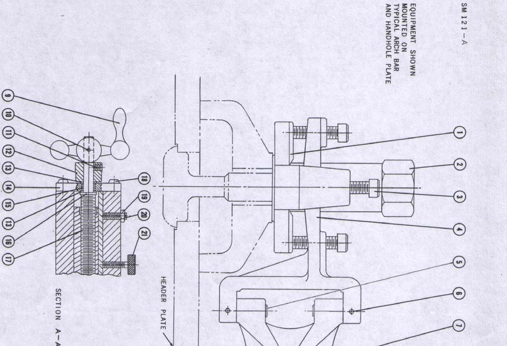
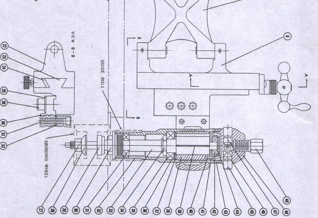
3 GUIDELINES The Wilson Pneumatic Handhole Seat Grinder will restore to a smooth, flat surface the gasket seat of any size or shape of handhole. Corroded, pitted, dented, scratched, fluid-abraded seats can be returned to perfect sealing condition with this tool. The Wilson grinder is a precision tool, ruggedly built for long usefulness under rough working conditions. The grinder assembly is mounted by attachment to the handhole plate stud of a nearby handhole. Then the assembly is leveled by adjusting the leveling screws with the motor assembly attached so that the grinding wheel is in the handhole. The motor is positioned up or down as required for the grinding wheel to take the desired cut from the existing seat. Then the motor is turned on and moved about the hole while the guide roller bears against the side of the handhole and the new seat is ground. Removal of one screw permits taking the motor and wheel out of the handhole for examination of the seat. (An accessory inspection mirror is furnished to facilitate this.) The wheel can then be replaced in the hole without disturbing the setting. The rugged bracket which supports the powerful grinder motor moves in dovetail ways to insure precise alignment and is clamped to prevent any deviation from the height setting made by turning the adjusting handle. Alternate mounting locations are provided for attaching the motor clamp to the dovetail slide when the handhole is in a header of 1-1/2" to 2-1/2" thickness. The grinder can reach 12-5/8 inches from the mounting stud to the far side of the handhole with a 2" dia. wheel attached. If a greater reach is needed, an accessory 5" long extension can be inserted between the motor clamp and slide bracket. Still greater reaches can be accommodated by the use of an extension mounting bar. Various seat widths can be ground by selecting the proper combinations of guide rollers and wheel diameters. For extra large handholes, an additional extension link attached, will accommodate for the increased contour to be ground. A cup brush may substitute for the grinding wheel if grinding is not needed and cleaning of the seat will suffice. The motor can be used for free-hand wire brushing by unbolting the clamp from the slide. Wear eye protection. 3

 has a left- hand thread, Be sure both blotters are between Flanges (Key 28 & 29) when mounting grinding wheel. 2. Mount grinder on plate stud of one handhole while grinding the seat of another.")
 from Slide Assembly (Key 8).")
. 4. Position grinding wheel by turning Handle (key 9). Lock assembly against movement.")
4 HOSES Attach hose whip supplied with Filter Lubricator No to air motor. LUBRICATION Air motors are lubricated with oil laden operating air. Use S.A.E. No. 10 oil or `Wilsolube" Pneumatic Motor Oil No in the Wilson Filter-Lubricator No Check that a fine mist of oil is always present in exhaust air. Keep hinges, dovetail, guide roller and screw threads coated with light oil. EQUIPMENT SELECTION 1. Measure handhole seat width. Select and attach guide roller to motor. See chart on last page. Note that Roller Retainer (Key 30) has a left- hand thread, Be sure both blotters are between Flanges (Key 28 & 29) when mounting grinding wheel. 2. Mount grinder on plate stud of one handhole while grinding the seat of another. The long Mounting Nut (Key 2) has a l"-8 thread. For a handhole stud with a 7/8"-9 thread, use Adapter No For a 3/4"-lO thread, use No OPERATION RECOMMENDED OPERATING AIR PRESSURE 90 PSI 1. To avoid damage to the grinding wheel, temporarily remove Motor Assembly (No, ) from Slide Assembly (Key 8). Unscrew Cap Screw (Key 26) with washer. 2. Attach mounting assembly (No ) to the handhole plate stud with Mounting Nut (key 2) in the general direction of the seat to be ground. 3. Place motor assembly in the handhole and bolt its clamp with cap screw and washer to Slide Bracket (key 23). 4. Position grinding wheel by turning Handle (key 9). Lock assembly against movement. Alternately set the (4) Leveling Screws (key3) and the slide height to position the grinding wheel squarely to the existing handhole seat. 5. For a light cut, turn on motor and adjust slide handle. Move motor until guide roller touches handhole side. Then, with the roller in contact with hole wall, move the motor around hole. Graduations on micrometer thimble are in thousands of an inch. 6. Avoid a rapid breakdown of the grinding wheel face, by taking a series of light cuts. 7. Unbolt motor to examine seat surface with inspection mirror (No ). 4
5 KIT LIST DESCRIPTION QTY. CAT. NO. TOOL BOX HANDHOLE SEAT GRINDER ASS Y MOTOR ASSEMBLY WITH CLAMP MOUNTING ASSEMBLY HOSE WHIP (8' LONG - 3/8 I.D.) EXTENSION ARM ASSEMBLY CUP BRUSH, 2" DIA GRINDING WHEEL, 2" (COARSE GRIT) GRINDING WHEEL, 2" (FINE GRIT) GUIDE ROLLER (1-5/8" DIA.) GUIDE ROLLER (1-9/16" DIA.) GUIDE ROLLER (1-1/2" DIA.) GUIDE ROLLER (1-7/16" DIA.) NP ADAPTER (1"-8M X 7/8-9F) NP ADAPTER (1"-8M X 3/4-1OF) /16" HEX. KEY /16" HEX. KEY /64" HEX. KEY WRENCH, 9/16" X 7/16" WHEEL DRESSING STONE INSPECTION MIRROR FILTER-LUBRICATOR ASSEMBLY AIR LINE FILTER HEX. NIPPLE - BRASS AIR LINE LUBRICATOR
6 PARTS LIST 6
7 7
8 PARTS LIST Key Description Part No. Handhole Seat Grinder Mounting Assembly Leveling Plate Mounting Nut Cap Screw Leveling Bracket Link Pin (4) Roll Pin (4) Link Slide Assembly Handle Roll Pin Set screw Micrometer Dial Washer Index Plate Assembly Index Plate Bearing Sleeve Washer Lead Screw Button Head Screw (2) Hex Nut (2) Front Flange (2) Rear Flange (2) Dovetail Body Slide Bracket Gib Washer Cap Screw Key Description Part No. Motor & Clamp Assembly Motor &Throttle Housing Hex Nut Front Flange Rear Flange Retainer Ball Bearing Motor Housing Spindle 4 slots Front Bearing Nut Ball Bearing Front Spacer Front Plate Cylinder Rotor Blades (set of 4) Pin Rear Plate Ball Bearing Nameplate Rear Plate Plug Throttle Assembly Push Button ON O-Ring Push Button OFF Throttle Housing Bushing with Screen Motor Clamp Assembly Motor Clamp Cap Screw Gasket
9 ACCESSORIES This can be useful for extra long reach or to avoid obstructions. The nut, at one end, is to be screwed onto a handhole plate stud. The grinder mounting assembly is then attached to the bar screw which may be placed in any of the four 3-3/8 spaced holes. (13-1/2 max.) A screw within the bar screw provides support for added rigidity. EXTENSION LINK For extra large handhole, an additional extension link attached will accommodate for the increased contour to be ground. Simply attach extension link between link (key7) and dovetail body (key 22). For a flawless reassembly leave link pins (key 5) in their prior location. INDICTOR CLAMP Additional convenience can be secured by using a separate Indicator Clamp Assembly., so that the motor does not have to be moved in and out of the motor clamp. ALIGNMENT INDICATOR 1043 This device greatly facilitates set-up. It is mounted in place of the motor. The serrations shown are on a blade which is brought into contact with the wall of the handhole. A pointer attached to the blade indicates the alignment of the mounting with respect to the hole. If the equipment is leveled to align with the hole wall, the subsequent grinding cut will be square with the hole. 9
10 MAINTENANCE Rotor Blades Replace if broken or worn 1/16 below slot top. Rotor Spindle A dropped tool may have a bent spindle. Check for straightness and replace if necessary. Cylinder and Rear End Plate Replace if surface is gouged or pitted from rust or moisture. Ball Bearing Clean dirty ball bearings in kerosene and flush with clean light oil (SAE10). All ball bearings should turn smoothly and freely with no noticeable looseness. Air Screen Clean air screen in Bushing (key 49) by reverse flushing. Caution Rust Before storing tool, put a good amount of oil into motor. Disassembly 1. Unscrew Motor Housing (key 32) from Throttle Housing (key 48). 2. Push out Rotor Assembly (key 33) to 44). 3. Pull Rear Plate Assembly (key40 to 44) off rotor, freeing cylinder and blades. Disassemble above only for parts replacement. Reassembly Follow above steps in reverse. 10
11 SELECTION CHART FOR GUIDE ROLLER AND WHEEL Seat Width Grinding Wheel Guide Roll Coarse Grit Fine Grit Dia. (in) Inch MM Cat. No Cat No. Dia.(in) Cat. No. 3/ / / / / / / / / / / / / / / / / / / / / / / / / / / / / / / / / / / Caution: Be sure that the wheel being used with the grinder complies with the requirements established in the American Standard Safety Code for The use, Care and Protection of Abrasive Wheels A.S.A. B
12 SPECIFICATIONS Model no Free Speed (RPM) Air Pressure psi 90 Air Inlet 1/4 NPT Hose 3/8 I.D. Minimum Air Speed 22 CFM Spindle 3/8-24 UNF-2 12 Thomas C. Wilson, Inc th Avenue, Long Island City, New York Tel: (718) Fax: (718)
General Safety and Maintenance Manual
 General Safety and Maintenance Manual 3 H.P HORIZONTAL GRINDERS CAPACITY -6 Inch (150 mm) or 8 Inch (200 mm) Type 1 Wheels -Any Type 16, 17, 17R, 18 or 18R Cone Wheels w/ 5/8-11 Mounting 3 H.P HORIZONTAL
General Safety and Maintenance Manual 3 H.P HORIZONTAL GRINDERS. and Thread RPM T1-5/8-11 X 1.9. Lever. Lever. Handle
 HENRY TOOLS Industrial Airtools at Work General Safety and Maintenance Manual 3 H.P HORIZONTAL GRINDERS 3 H.P HORIZONTAL GRINDERS Capacity: -6 Inch (150 mm) or 8 Inch (200 mm) Type 1 Wheels -Any Type 16,
MODELS 49 RA 49 RAZ 49 RAC
 General Safety and Maintenance Manual MODEL grinder featuring a rear exhaust. Model Number Exhaust Direction REAR Throttle Type (L) Lever or (K) Safety Lever Speed 12000 to 14000 R.P.M (13500rpm is standard)
General Safety and Maintenance Manual
 General Safety and Maintenance Manual 4 H.P HORIZONTAL GRINDERS CAPACITY -6 Inch (150 mm) or 8 Inch (200 mm) Type 1 Wheels -Any Type 16, 17, 17R, 18 or 18R Cone Wheels w/ 5/8-11 Mounting 65H Series 4 H.P
VARIABLE SPEED WOOD LATHE
 MODEL MC1100B VARIABLE SPEED WOOD LATHE INSTRUCTION MANUAL Please read and fully understand the instructions in this manual before operation. Keep this manual safe for future reference. Version: 2015.02.02
OPERATION AND MAINTENANCE FOR MODEL MRV050A REVERSIBLE
 OPERATION AND MAINTENANCE FOR MODEL MRV050A REVERSIBLE MANUAL AIR MOTOR 04666770 Edition 1 April, 1999 IMPORTANT SAFETY INFORMATION ENCLOSED. READ THIS MANUAL BEFORE OPERATING TOOL. FAILURE TO OBSERVE
Orig Model 236B ID Tracking Module TABLE OF CONTENTS
 92-1349 Orig. 080319 TABLE OF CONTENTS CUSTOMER MESSAGE Inside Front Cover SAFETY PRECAUTIONS 3 GENERAL DESCRIPTION 6 SPECIFICATIONS 7 MAINTENANCE 8 INSTALLATION 10 OPERATION 12 TROUBLE SHOOTING 17 ILLUSTRATED
Power Output. Spindle. 7.7 Inches (196 cm) 11.0 Lbs. (5.0 Kg)
 11.0 Lbs. (5.0 Kg)") HENRY TOOLS Industrial Airtools at Work General Safety and Maintenance Manual SUPER HEAVY DUTY VERTICAL GRINDERS 4 Horsepower Vertical Grinders 4 HORSEPOWER Model Number Throttle Type Power Output Weight
HENRY TOOLS Industrial Airtools at Work General Safety and Maintenance Manual SUPER HEAVY DUTY VERTICAL GRINDERS 4 Horsepower Vertical Grinders 4 HORSEPOWER Model Number Throttle Type Power Output Weight
Model 204B-EM Elbow Mandrels Rev TABLE OF CONTENTS
 92-0697 Rev. 970131 Model 204B-EM Elbow Mandrels TABLE OF CONTENTS CUSTOMER MESSAGE Inside Front Cover SAFETY PRECAUTIONS 3 GENERAL DESCRIPTION 6 MAINTENANCE 7 OPERATION 8 TROUBLE SHOOTING 11 ACCESSORIES
VARIABLE SPEED WOOD LATHE. Model DB900 INSTRUCTION MANUAL
 VARIABLE SPEED WOOD LATHE Model DB900 INSTRUCTION MANUAL 1007 TABLE OF CONTENTS SECTION...PAGE Technical data.. 1 General safety rules....1-3 Specific safety rules for wood lathe.....3 Electrical information.4
Instructions for Stone Cutting Machine
 Technical data Kg. Instructions for Stone Cutting Machine SCM600 3HP 2800rpm IP55 SCM800 3HP 2800rpm IP55 SCM1000 2800rpm IP55 SCM1200 2800rpm IP55 L=600 B=85(165) L=800 B=85(175) 500x510 0 or 45 600lt/h
ELECTRIC TUBE ROLLER
 41238-0000 ELECTRIC TUBE ROLLER OPERATING INSTRUCTIONS & SERVICE MANUAL Rev: A, 8/20/2007 TO REDUCE THE RISK OF INJURY AND EQUIPMENT DAMAGE USER MUST READ AND UNDERSTAND OPERATOR S MANUAL. Thomas C. Wilson,
Model SQM-2AC Squaring Module Rev TABLE OF CONTENTS
 92-0714 Rev. 970428 Model SQM-2AC Squaring Module TABLE OF CONTENTS CUSTOMER MESSAGE Inside Front Cover SAFETY PRECAUTIONS 3 GENERAL DESCRIPTION 6 SPECIFICATIONS 7 MAINTENANCE 8 OPERATION 9 CUTTING SPEEDS
Maintenance Information
 16601023 Edition 2 January 2014 Air Impact Wrench 2705P1 Maintenance Information Save These Instructions Product Safety Information WARNING Failure to observe the following warnings, and to avoid these
GENERAL OPERATIONAL PRECAUTIONS PRECAUTIONS ON USING CUT-OFF MACHINE
 GENERAL OPERATIONAL PRECAUTIONS WARNING! When using electric tools, basic safety precautions should always be followed to reduce the risk of fire, electric shock and personal injury, including the following.
JARVIS. Model BR-3 Blade Reconditioner ... EQUIPMENT TABLE OF
 - Model BR-3 Blade Reconditioner EQUIPMENT SELECTION.......... Ordering No. TABLE OF CONTENTS............................ Page Model BR-3 (100 mm Blade) 115V/60Hz............ 4011003 220V/50Hz............
Rev B C-RING TOOL VA0375 ½ in. OPERATING MANUAL
 Rev B 4-30-0 C-RING TOOL VA0375 ½ in. OPERATING MANUAL Operational Instructions for Vertex C-Ring Tool VA0375 Vertex Fasteners is committed to providing our customers with world-class customer service
Heavy Duty Mechanic s Kit
 Heavy Duty Mechanic s Kit 00 Safety Warning Read all instructions and safety warnings prior to operation. Failure to do so could result in equipment damage, personal injury or even death. CAUTION 00: FAILURE
PNEUMATIC C-RING TOOLS SC73462 SAFETY INSTRUCTIONS. WARNINGS Always read tool manual before operating.
 PNEUMATIC C-RING TOOLS SC73462 SAFETY INSTRUCTIONS WARNINGS Always read tool manual before operating. Always wear safety glasses while operating or while in the vicinity of a tool in operation. For testing,
PRODUCT MANUAL 5-IN-1 MITER SAW STATION *SAVE THIS MANUAL FOR FUTURE REFERENCE
 PRODUCT MANUAL 5-IN-1 MITER SAW STATION *SAVE THIS MANUAL FOR FUTURE REFERENCE 92778 1 GENERAL SAFETY INFORMATION For your safety, please read these instructions carefully before use and keep them in the
Quick Set Dovetail Jig
 Quick Set Dovetail Jig FOR HELP OR ADVISE ON THIS PRODUCT PLEASE CALL OUR CUSTOMER SERVICE HELP LINE : 01509 500359 THE MANUFACTURER RESERVES THE RIGHT TO ALTER THE DESIGN OR SPECIFICATION TO THIS PRODUCT
PLATE JOINER 4 INCH. ASSEMBLY and OPERATING INSTRUCTIONS. Distributed Exclusively by Harbor Freight Tools
 PLATE JOINER 4 INCH 38437 ASSEMBLY and OPERATING INSTRUCTIONS Distributed Exclusively by Harbor Freight Tools 3491 Mission Oaks Blvd., Camarillo, CA 93011 Copyright 1998 by Harbor Freight Tools. All rights
GENERAL OPERATIONAL PRECAUTIONS PRECAUTIONS ON USING DISC GRINDER
 GENERAL OPERATIONAL PRECAUTIONS WARNING! When using electric tools, basic safety precautions should always be followed to reduce the risk of fire, electric shock and personal injury, including the following.
pneumatic c-ring tool
 pneumatic c-ring tool hc5 HC5 WARNINGS! Always read tool manual before operating tool. Always wear safety glasses when operating or while in the area where a tool is being used. When test cycling tool
JARVIS. Model Brisket Scissor EQUIPMENT... TABLE OF
 Model 423-17 Brisket Scissor EQUIPMENT SELECTION... Ordering No. TABLE OF CONTENTS... Page Model 423--17... 4037003 Air Filter / Regulator / Lubricator 3022003 Air Hose Assembly... 3059018 Balancer...
Model CBM-3 Counterbore Module Rev TABLE OF CONTENTS
 92-0227 Rev. 070529 Model CBM-3 Counterbore Module TABLE OF CONTENTS CUSTOMER MESSAGE Inside Front Cover SAFETY PRECAUTIONS 3 GENERAL DESCRIPTION 6 SPECIFICATIONS 7 MAINTENANCE 9 OPERATION 10 CUTTING SPEEDS
SAFETY INSTRUCTIONS. WARNINGS Always read tool manual before operating.
 SAFETY INSTRUCTIONS WARNINGS Always read tool manual before operating. Always wear safety glasses while operating or while in the vicinity of a tool in operation. For testing, always cycle tool away from
3/8 Butterfly Air Impact Wrench
 3/8 Butterfly Air Impact Wrench 37730 ASSEMBLY AND OPERATING INSTRUCTIONS 3491 Mission Oaks Blvd., Camarillo, CA 93011 Visit our Web site at http://www.harborfreight.com Copyright 2004 by Harbor Freight
8-Ton Manual Splitter OWNER S MANUAL
 8-Ton Manual Splitter OWNER S MANUAL WARNING: Read carefully and understand all ASSEMBLY AND OPERATION INSTRUCTIONS before operating. Failure to follow the safety rules and other basic safety precautions
Sink BULL INSTRUCTION MANUAL. with Rapid Z -CUT & Rapid Z -DRUM
 Sink BULL with Rapid Z -CUT & Rapid Z -DRUM INSTRUCTION MANUAL Please read this instruction manual thoroughly to ensure safety and the correct use of this tool. Keep this manual in a place where operators
Series Inline Oscillating Saw
 Parts Manual Ersatzteil Liste 45-8185 12-2065 Series Inline Oscillating Saw IMPORTANT: Read and comply with safety and operating instructions contained in this manual. For additional product information
General Four-Way Operation, Maintenance & Service Manual
 General Four-Way Operation, Maintenance & Service Manual SCOPE Included in the following pages you will find assembly drawings, exploded views, parts lists, assembly tips, operational descriptions and
18 GAUGE ELECTRIC METAL SHEAR
 241-9895 18 GAUGE ELECTRIC METAL SHEAR Operator s Manual SAVE THIS MANUAL You will need this manual for safety instructions, operating procedures and warranty. Put it and the original sales receipt in
B-Too Drilling and Tapping Machine Instruction and Maintenance Manual
 B-Too Drilling and Tapping Machine Instruction and Maintenance Manual Thank you for your purchase of the B-Too Drilling and Tapping Machine. Please read and understand this short operation manual. Our
ATBG280/6 Bench Grinder Bench Grinder ATBG280/6 230V-50Hz 280 Watt 150mm x 25mm Wheel size
 Bench Grinder ATBG280/6 230V-50Hz 280 Watt 150mm x 25mm Wheel size SPECIFICATIONS Model Number : ATBG280/6 Nominal Voltage Power Consumption No load speed Wheel size Weight 230Volt 50Hz 280 Watts 2880
Pneumatic Drill / / Technical Specification
 CS UNITEC Pneumatic Drill 2 2502 0010 / 2 2502 0030 2 2506 0010 / 2 2506 0030 Technical Specification Model with Lever Throttle Model with Twist Throttle with Selfresetting 2 2502 0010 2 2502 0030 2 2506
C-RING TOOL VA0278 OPERATING MANUAL
 C-RING TOOL VA0278 OPERATING MANUAL 1798 Sherwin Avenue Des Plaines, IL 60018 U.S.A. EMAIL: vertex@leggett.com PHONE: 847-768-6139 FAX: 847-768-7192 Operational Instructions for Vertex C-Ring Tool VA0278
The DeltaGrip System. Safety and Operating Instructions. Trigger. Air Supply Connection. Handle Assembly. Air Line Assembly.
 The DeltaGrip System Safety and Operating Instructions Trigger Air Supply Connection Handle Assembly Air Line Assembly Punch Die Pneumatic Diaphragm Assembly Shackle, Pin & Jam Nut Jaw Frame Shoulder Screw
H8508 Impact Wrench SERVICE MANUAL. Model (Serial Code FWN) Model (Serial Code FWP)
 Model (Serial Code FWP)") SERVICE MANUAL H8508 Impact Wrench Model 48755 (Serial Code FWN) Model 48760 (Serial Code FWP) Read and understand all of the instructions and safety information in this manual before operating or servicing
SERVICE MANUAL H8508 Impact Wrench Model 48755 (Serial Code FWN) Model 48760 (Serial Code FWP) Read and understand all of the instructions and safety information in this manual before operating or servicing
Angle Grinder MODEL 9553B MODEL 9555B
 ENGLISH Angle Grinder MODEL 9553B MODEL 9555B 006649 DOUBLE INSULATION I N S T R U C T I O N M A N U A L WARNING: For your personal safety, READ and UNDERSTAND before using. SAVE THESE INSTRUCTIONS FOR
HC715 / HC716 WARNINGS!
 pneumatic c-ring tool HC75 / HC76 HC75 / HC76 WARNINGS! Always read tool manual before operating tool. Always wear safety glasses when operating or while in the area where a tool is being used. When test
pneumatic c-ring tool
 pneumatic c-ring tool HC56 HC56 WARNINGS! Always read tool manual before operating tool. Always wear safety glasses when operating or while in the area where a tool is being used. When test cycling tool
SHEREX FASTENING SOLUTIONS PNEUMATIC SPIN-SPIN RIGHT ANGLE INLINE STYLE RIVET NUT INSTALLATION TOOL SSG-913 MANUAL
 SHEREX FASTENING SOLUTIONS PNEUMATIC SPIN-SPIN RIGHT ANGLE INLINE STYLE RIVET NUT INSTALLATION TOOL SSG-913 MANUAL SSG-913 Specifications R.P.M. - 400 *Air Pressure - 80-110 psi (oiled) Weight - 2.3 lbs.
HOLE CUTTER SHARPENER ASSEMBLY & SERVICE MANUAL
 HOLE CUTTER SHARPENER ASSEMBLY & SERVICE MANUAL WARNING You must thoroughly read and understand this manual before operating the equipment, paying particular attention to the Warning & Safety instructions.
SECTION 9: PARTS. Table Breakdown REF PART # DESCRIPTION REF PART # DESCRIPTION
 SECTION 9: PARTS Table Breakdown 1 2 3 4 5 6 7 8 9 10 11 12 13 14 15 16 17 18 19 20 21 22 23 24 23 25 17 26 27 8 1 P0675001 CAP SCREW M8-1.25 X 30 15 P0675015 SUPPORT BLOCK 2 P0675002 TABLE SUPPORT BLOCK
SHEREX FASTENING SOLUTIONS PNEUMATIC SPIN-SPIN INLINE STYLE RIVET NUT INSTALLATION TOOL SSG-902 MANUAL
 SHEREX FASTENING SOLUTIONS PNEUMATIC SPIN-SPIN INLINE STYLE RIVET NUT INSTALLATION TOOL SSG-902 MANUAL SSG-902 Specifications R.P.M. - 1500 *Air Pressure - 60-90 psi (oiled) Weight - 2 lbs. (0.9 kg) Air
Rev Model 103 REP TM, Rapid End Prep Machine TABLE OF CONTENTS
 92-0131 Rev. 960503 Model 103 REP TM, Rapid End Prep Machine TABLE OF CONTENTS CUSTOMER MESSAGE Inside Front Cover SAFETY PRECAUTIONS 3 GENERAL DESCRIPTION 6 SPECIFICATIONS 7 MAINTENANCE 8 OPERATION 10
12 Slip Roll. Model Assembly & Operating Instructions
 12 Slip Roll Model 36698 Assembly & Operating Instructions Diagrams within this manual may not be drawn proportionally. Due to continuing improvements, actual product may differ slightly from the product
Maintenance & Parts list for:
 Maintenance & Parts list for: Industrial gun GB 2 Juni 2017 This Maintenance & Parts list for industrial gun is prepared by : Winchester Europe Service V. Parbst & Søn as a comprehensive maintenance guide
Operating Manual 6 Industrial Bench Grinder ATBG280/
 Operating Manual 6 Industrial Bench Grinder ATBG280/6 804531 40 Year Australian Heritage The reputable name in bench grinders for 40 years Protect yourself and others by observing all safety information,
4.2 - PUMP MAINTENANCE MODELS: AC, AS, WC, WS
 4.2 - PUMP MAINTENANCE MODELS: AC, AS, WC, WS 4.2.1 - EXPLODED VIEW DRAWING REF NO. 1 2 4 QTY 3 1 1.5 5 ¾ HP HP HP HP HP DESCRIPTION PART # 1 CASE 1.25 x 1 NPT 018266 1 CASE 1.25 X 1 NPT 018268 1 CASE
JARVIS. Model25CL-4,5,6 Hock Cutter and Loin Dropper. 25CL--5 Front Legs and Horns. 25CL--4 Hind Legs and Horns. 25CL--6 Loins
 Model25CL-4,5,6 Hock Cutter and Loin Dropper 25CL--4 Hind Legs and Horns 25CL--5 Front Legs and Horns 25CL--6 Loins EQUIPMENT SELECTION... Ordering No. TABLE OF CONTENTS... Page 25CL--4... 4025007 25CL--5...
ATV Disc OWNER S MANUAL
 ATV Disc OWNER S MANUAL WARNING: Read carefully and understand all ASSEMBLY AND OPERATION INSTRUCTIONS before operating. Failure to follow the safety rules and other basic safety precautions may result
Model MFC-2 Split Frame Clamshell Operation and Parts Manual
 Model MFC- Split Frame Clamshell Operation and Parts Manual Corporate H&S Tool, Inc. Mail: P.O. box Wadsworth, OH Shipping: Weber Dr. Wadsworth, OH U.S.A. Tel: +-0--0 Fax: +-0-- www.hstool.com e-mail:
INSTRUCTION BOOK AND PARTS LIST
 Rag Cutter MODEL WE WARNING This machine is equipped with a very sharp knife. Keep hands, arms, and hair away from the knife area at all times. Misuse of this machine or failure to follow all safety instructions
Dust RIGHT. Shop Vacuum Dust Hose Reel Instructions. For safe and effective operation, please read these instructions fully before use.
 Dust RIGHT Shop Vacuum Dust Hose Reel Instructions For safe and effective operation, please read these instructions fully before use. GENERAL SAFETY WARNINGS This tool is designed for specific applications
Handling instructions
 Router Model M 2SC Handling instructions Note: Before using this Electric Power Tool, carefully read through these HANDLING INSTRUCTIONS to ensure efficient, safe operation. It is recommended that these
PARTS LIST. Model MFT-HD Cleco
 PARTS LIST Model MFT-HD Cleco 0 0 0 0 0 0 0 0 HD-0- Centershaft HD-0- Centershaft Screw HD-0- Lift Collar HD-0- Eyebolt HD-0- Hex Nut HD-0- Draw Rod HD-0- Washer - Draw Rod HD-0- Face Plate, " Diameter
HYDRAULIC MOWER AHRM4H, HRM48H Parts Catalog INDEX HOME TRACTOR ATTACHMENTS APPLICATION CHART
 R Ingersoll HYDRAULIC MOWER AHRM4H, HRM48H Parts Catalog 8-3091 HOME TRACTORS ATTACHMENTS PAINT GENERAL INFO INDEX Deck. Belt and Idler Pulley...5 Mounting Bracket...7 Rear Wheels...7 Hydraulic Drive...9-13
Operating, Servicing, and Safety Manual Model # 100 Standard Hydraulic Tubing Notcher Model #100-U Heavy Duty Hydraulic Tubing Notcher
 Operating, Servicing, and Safety Manual Model # 100 Standard Hydraulic Tubing Notcher Model #100-U Heavy Duty Hydraulic Tubing Notcher Model # 100 Standard Model #100-U Heavy Duty CAUTION: Read and Understand
SERVICE PARTS LIST PAGE 1 OF 6 BASE ASSEMBLY SPECIFY CATALOG NO. AND SERIAL NO. WHEN ORDERING PARTS 12" DUAL BEVEL COMPOUND MITER SAW B27B
 PAGE 1 OF 6 BASE ASSEMBLY 00 0 EXAMPLE: Component Parts (Small #) Are Included When Ordering The Assembly (Large #). SPECIFY CATALOG NO. AND NO. WHEN ORDERING PARTS = Part number change from previous service
LPK1550 Hydraulic Crimping Tool 15-ton
 SERVICE MANUAL LPK1550 Hydraulic Crimping Tool 15-ton Serial Code FYF Read and understand all of the instructions and safety information in this manual before operating or servicing this tool. Register
LU6X-130 Instructions and Parts List (including LU6X Basic) Operating Instructions
 Operating Instructions") LORTONE LU6X-130 Item # 061-092 LU6X Basic Item # 061-090 LU6X-130 Instructions and Parts List (including LU6X Basic) Operating Instructions Introduction The LU6X is one the most versatile pieces of equipment
LORTONE LU6X-130 Item # 061-092 LU6X Basic Item # 061-090 LU6X-130 Instructions and Parts List (including LU6X Basic) Operating Instructions Introduction The LU6X is one the most versatile pieces of equipment
PLANISHING HAMMER STAND OWNER S MANUAL
 PLANISHING HAMMER STAND OWNER S MANUAL WARNING: Read carefully and understand all INSTRUCTIONS before operating. Failure to follow the safety rules and other basic safety precautions may result in serious
Mechanical Frappe Press
 Mechanical Frappe Press Operation Manual CONTENTS OPERATIONAL INSTRUCTIONS PRECAUTIONS PART NAMES INCLUDED ITEMS BASIC OPERATION MAINTENANCE REPLACEMENT PARTS Thank you for using The Frapptastic Five Mechanical
OPERATOR'S MANUAL 46" SNOW BLADE. Model Numbers OEM IMPORTANT: READ SAFETY RULES AND INSTRUCTIONS CAREFULLY
 OPERATOR'S MANUAL 46" SNOW BLADE Model Numbers 190-833-OEM IMPORTANT: READ SAFETY RULES AND INSTRUCTIONS CAREFULLY MTD PRODUCTS INC. P.O. BOX 368022 CLEVELAND, OHIO 44136-9722 PRINTED IN U.S.A. FORM NO.
12mm (Max) 6mm (Max) 82mm (Max) 12mm (Max) 6mm (Max)
 6mm (Max) 82mm (Max) 12mm (Max) 6mm (Max)") 1 1 2 2 3 3 82mm (Max) 12mm (Max) 12mm (Max) 6mm (Max) 4 4 5 6 8 6mm (Max) 0.5 0mm 1 5 6 7 7 8 9 9 A = B 10 11 12 D B 1 13 14 15 0 C A D E 16 17 18 F G D B N H J G I K 19 A 20 G L 21 C K 1mm L M 1mm 22
1 1 2 2 3 3 82mm (Max) 12mm (Max) 12mm (Max) 6mm (Max) 4 4 5 6 8 6mm (Max) 0.5 0mm 1 5 6 7 7 8 9 9 A = B 10 11 12 D B 1 13 14 15 0 C A D E 16 17 18 F G D B N H J G I K 19 A 20 G L 21 C K 1mm L M 1mm 22
ACREAGE SEEDER / PLANTER OWNER S MANUAL
 ACREAGE SEEDER / PLANTER OWNER S MANUAL WARNING: Read carefully and understand all ASSEMBLY AND OPERATION INSTRUCTIONS before operating. Failure to follow the safety rules and other basic safety precautions
Fisher 667 Diaphragm Actuators Size 80 and 100
 Instruction Manual 667 Size 80 and 100 Actuators Fisher 667 Diaphragm Actuators Size 80 and 100 Contents Introduction... 1 Scope of Manual... 1 Description... 2 Specifications... 2 Maximum Pressure Limitations...
3 POINT HITCH LOGSPLITTER
 3 POINT HITCH LOGSPLITTER OPERATOR S MANUAL AND PARTS LIST TABLE OF CONTENTS SECTION PAGE 1. GENERAL INFORMATION 1 2. SAFETY GUIDELINES 2 2.1 DEFINITIONS 2 2.2 SAFE OPERATING PROCEDURE 3 3. LOG SPLITTER
OPERATING INSTRUCTIONS AND PARTS LISTS
 3889560 REEL ALIGNMENT GAGE OPERATING INSTRUCTIONS AND PARTS LISTS WARNING You must thoroughly read and understand this manual before operating the equipment, paying particular attention to the Warning
YALE FIGURE 500 & 500R CLOSURE OPERATION AND MAINTENANCE INSTRUCTIONS
 YALE FIGURE 500 & 500R CLOSURE OPERATION AND MAINTENANCE INSTRUCTIONS IMPORTANT INFORMATION Note To Supervisor: Please share this information with your employees and make sure they have received training
SERVICE MANUAL LHFS
 SERVICE MANUAL LHFS-210003 Pruner Serial Code FFD Read and understand all of the instructions and safety information in this manual before operating or servicing this tool. Register this product at www.greenlee.com
.com. More than a machine. Power your life. Operating Manual
 Operating Manual www.maxnovomachine +86-514-87892928 info@maxnovomachine Dear Customer, Thank you very much for purchasing a product made by MAXNOVO MACHINE. Our machines offer a maximum of quality, technical
Ideal 1000 Manual
 Ideal 1000 Manual 20016-6111 Contents 1. Introduction.................................................................... 2 1.0 Introduction................................................................
Square Wheel Belt Grinder Models: 4103, 4106, and 4126AC
 This Manual is Bookmarked Operating Instructions Parts Manual Square Wheel Belt Grinder Models: 4103, 4106, and 4126AC WHM TOOL GROUP 2420 Vantage Drive Elgin, Illinois 60123 Ph.: 800-274-6848 www.wmhtoolgroup.com
MUELLER GAS. DH-5/EH-5 Drilling. Reliable Connections. DH-5 Drilling Machine General Information 2. EH-5 Drilling Machine General Information 3
 operating Instructions manual MUELLER GAS TAble of contents PAGE DH-5 Drilling Machine General Information 2 DH-5/EH-5 Drilling EH-5 Drilling Machine General Information 3 Operating Instructions 4-5 DH-5
GENERAL OPERATIONAL PRECAUTIONS
 GENERAL OPERATIONAL PRECAUTIONS WARNING! When using electric tools, basic safety precautions should always be followed to reduce the risk of fire, electric shock and personal injury, including the following.
SERVICE PARTS LIST PAGE 1 OF 6 BASE ASSEMBLY SPECIFY CATALOG NO. AND SERIAL NO. WHEN ORDERING PARTS 12" SLIDING COMPOUND MITER SAW
 PAGE 1 OF 6 BASE ASSEMBLY 00 0 CATALOG NO. EXAMPLE: SPECIFY CATALOG NO. AND NO. WHEN ORDERING PARTS 6955-20 1 02-80-0050 Thrust Bearing (1) 2 05-80-0510 M5 x 12mm Flat Head T-20 Screw (5) 3 05-81-0135
RIPPER PEDAL. Bearing / Axle Replacement. ( Disassembly )
") RIPPER PEDAL Bearing / Axle Replacement ( Disassembly ) 1 1. Use good quality tools to avoid stripping screw sockets. 2. When servicing your pedals, work on one side at a time to prevent parts from mixing
RIPPER PEDAL Bearing / Axle Replacement ( Disassembly ) 1 1. Use good quality tools to avoid stripping screw sockets. 2. When servicing your pedals, work on one side at a time to prevent parts from mixing
INSTRUCTION MANUAL. 125 mm (5 ) MODEL 9005B 125 mm (5 ) MODEL 9005BZ. DOUBLE I N S U LATlO N SPEC IF I CAT I 0 N S
 MODEL 9005B 125 mm (5 ) MODEL 9005BZ. DOUBLE I N S U LATlO N SPEC IF I CAT I 0 N S") 25 mm (5 ) MODEL 9005B 25 mm (5 ) MODEL 9005BZ INSTRUCTION MANUAL DOUBLE I N S U LATlO N SPEC IF I CAT I 0 N S No load speed (RPM) 0,000lmin. AMPS Overall Net Power Spindle (5 V) length weight supply cord
25 mm (5 ) MODEL 9005B 25 mm (5 ) MODEL 9005BZ INSTRUCTION MANUAL DOUBLE I N S U LATlO N SPEC IF I CAT I 0 N S No load speed (RPM) 0,000lmin. AMPS Overall Net Power Spindle (5 V) length weight supply cord
3pt 60 Spike Aerator OWNER S MANUAL
 3pt 60 Spike Aerator OWNER S MANUAL WARNING: Carefully read and understand all ASSEMBLY AND OPERATION INSTRUCTIONS before operating. Failure to follow the safety rules and other basic safety precautions
MI MI OPERATING MANUAL
 MODEL NO.: MI-76100 MI-76150 OPERATING MANUAL RULES for SAFE OPERATION MAGNUM INDUSTRIAL MI-76100 and MI 76150 DRILL PRESSES To help ensure safe operation, please take a moment to learn the how to operate
3 Emergency Breakaway Coupling
 SM64227 July 2008 Applicable addition manuals: N/A Aerospace Group Conveyance Systems Division Carter Ground Fueling Maintenance & Repair Manual 3 Emergency Breakaway Coupling Model 64227 Table of Contents
Gared Pro-S Portable Backstop
 Models: 9616 & 9618 Installation, Operation and Maintenance Instructions Please read all instructions before attempting installation or operation of these units SAVE THESE INSTRUCTIONS FOR FUTURE USE PUBLICATION
G01 through G10 Series Hydraulic Actuators Double-Acting with M11 Hydraulic Override Disassembly and Reassembly
 Service Instructions G01 through G10 Series Hydraulic Actuators Double-Acting with M11 Hydraulic Override Disassembly and Reassembly Service Instructions Table of Contents Table of Contents Section 1:
OPERATOR S MANUAL FOR MODEL BLADE GRINDER
 OPERATOR S MANUAL FOR MODEL 88-021 BLADE GRINDER Table of Contents Page Blade Grinder Safety and User Instructions 2 Unpacking the Grinder 5 Assembling the grinder 6 Adjusting the grinding angle 8 Adjusting
MUELLER. Improved, Centurion Series, Modern Improved, and 107. Fire Hydrants. Inserting Extension Sections. Reliable Connections
 insertion Instructions manual MUELLER Improved, Centurion Series, Modern Improved, and 107 table of contents PAGE Centurion Series Fire Hydrant Adding an Extension 2-3 Improved Fire Hydrant Inserting Extension
4.4 PUMP MAINTENANCE MODELS: DB, DC, DF, DG, DJ, DL
 4.4 PUMP MAINTENANCE MODELS: DB, DC, DF, DG, DJ, DL 4.4.1 EXPLODED VIEW DRAWING REF. QTY. DB DC DF DG DJ DL DESCRIPTION PART # 1 1 ADAPTOR FRAME 034007 2 12 LOCK WASHER 3/8 x 1/8 S.S. 034004 3 12 HEX HEAD
30DC Speed Lathe Manual
 30DC Speed Lathe Manual The Crozier Model 30DC Speed Lathe is our most popular model. It has many standard features not found on any other machine in its class or price range. Standard Features 3/4 HP
SAVE THIS MANUAL FOR FUTURE REFERENCE. WARNING: To reduce the risk of
 - ($ 0$$/ PP-,( /$( WARNING: To reduce the risk of injury, the user must read and understand the operator's manual before using this product. Part SP SAVE THIS MANUAL FOR FUTURE REFERENCE Printed in Taiwan
52 5 N. Instructions & Parts List. From the library of: Superior Sewing Machine & Supply LLC
 52 5 N Instructions & Parts List z L.f) N L!) _J w 0 0 ~ INSTRUCTION BOOK FOR MODEL 5 2 5 N 1. Starting. Attach the operation handle (No.54) to the machine and after confirming that the switch (No.56)
Model No: TC10. Parts Information: Tyre Changer - Automatic
 Page 1 of 11 1 TC10.01 BODY 2 TC10.02 COLUMN 3 TC10.03 HORIZONTAL ARM ASS'Y 4 TC10.04 WASHER 5 TC10.05 RUBBER FOOT 6 TC10.06 COVER 7 TC10.07 SCREW M14x42 8 TC10.08 PRESS COVER 9 TC10.09 STOP-UP 10 TC10.10
SERVICE INSTRUCTIONS Model 9670 Lubricant Pump
 TM TM SERVICE INSTRUCTIONS Model 9670 Lubricant Pump 9670 DESCRIPTION Model 9670 Lubricant Pump is designed to pump light to heavy oils directly from the original container. This design features a 10:1
Wheeler Rex Ashtabula, Ohio Tel: Fax:
 Wheeler Rex Ashtabula, Ohio Tel: 800 321 7950 Fax: 440 992 2925 wheeler@wheelerrex.com www.wheelerrex.com December 2012 There are three different types of shell cutters. Nominal Hole Size Part No. 4" 3395
MAINTENANCE CLEANING. MECHANICAL SEAL REPLACEMENT Refer to figures 1 and 2. SHIM ADJUSTMENT
 Please read and save this Repair Parts Manual. Read this manual and the General Operating Instructions carefully before attempting to assemble, install, operate or maintain the product described. Protect
SECTION 9: PARTS. Headstock
 SECTION 9: PARTS We do our best to stock replacement parts when possible, but we cannot guarantee that all parts shown are available for purchase. Call (800) 52-4777 or visit www.grizzly.com/parts to check
Mortising Attachment
 Mortising Attachment Owner s Manual WARNING: Read carefully and understand all ASSEMBLY AND OPERATION INSTRUCTIONS before operating. Failure to follow the safety rules and other basic safety precautions
MUELLER E-5TM. and D-5TM. Drilling Machines. Reliable Connections. E-5 General Information 2. D-5 General Information 3. Operating Instructions 4-5
 operation Instructions manual MUELLER E-5TM and D-5TM TAble of contents PAGE E-5 General Information 2 Drilling Machines D-5 General Information 3 Operating Instructions 4-5 E-5 Parts 6 D-5 Parts 7! WARNING:
Astro-Physics Inc. 400QMD Lubrication/Maintenance Guide
 Astro-Physics Inc. 400QMD Lubrication/Maintenance Guide The following guidelines should be followed to lubricate the three main parts of the 400QMD mount. The QMD stands for Quartz Micro-Drive controller.