Building a 30 Turntable
|
|
|
- Angela Chandler
- 5 years ago
- Views:
Transcription
 sufficient for a Bachmann Ten-Wheeler and a Porter 0-4-0 with its battery car.")
1 Building a 30 Turntable Introduction I wanted a turntable at the North end of my Mystic Mountain railroad to turn trains for point-topoint running and for visual interest. After measuring all my engines I decided I needed a 30 turntable. This is (just) sufficient for a Bachmann Ten-Wheeler and a Porter with its battery car. My requirements were: inexpensive and low maintenance. The second meant not using wood or steel. I could use acrylic, but resin casting is our business so I have equipment for making molds and casting parts and decided to go this route for the turntable bridge. I also have experience casting in white concrete which would be useful to make the pit walls. The design The bridge would be made with two (identical) side panels joined with spacers. The pit walls would be cast on a circle of wood and then slid into place on a concrete base. The center pivot locates the bridge in the pit but supports no weight. The weight is supported by the two wheels at the ends of the bridge which ride on the rail in the bottom of the pit. With this in mind perhaps you can see that the pivot must be in the exact center of the pit and bridge so that the bridge ends do not contact the pit side at any point. And the height of the pit side above the pit rail must be

2 consistent around the pit so that the vertical alignment of the bridge track with the other turntable tracks will be correct all around the circle. The bridge is formed from two detailed sides glued together with spacers. You can choose the width you want easily this way. The center spacers include the center hole for the pivot point. The end spacers also mount the support wheels that ride on the pit rail. Building the bridge The basic steps to build the bridge are: 1) Create a single detailed side panel, 2) Create spacers for a single side of the bridge, 3) Make silicone molds for above, 4) Cast two bridge sides and two sets of spacers from resin, 5) Glue bridge sides with spacers and paint, 6) Glue bearing into center holes in spacers, Make a bridge side out of acrylic or wood, whatever you re most comfortable working with. Make the length 1/2 shorter than the final length to allow 1/4 clearance at each end between bridge and pit. I used Plastruct tee shapes to form gussets in the bridge side. Close-up of bridge side master Build a 2.75 high box from four pieces of 1x3 stock. The box should be ½ larger on all sides than the bridge side. Place on Wilsonart or Pergo tiles, mark inside of box with a pencil. Remove the box and use a small amount of hot glue to secure the back side of the bridge side to the tile centered in the box. Replace the box and use hot glue all around outside of the box to secure and seal it. Mix silicone and pour to ½ over the bridge. Let the silicone set for 1-2 days. Use a chisel or putty knife to split the box open and free the box from the tile; remove. Use a putty knife to free the mold from the box and tile. Pry the mold from the sides of bridge; remove the bridge from the mold. Re-glue the box together and glue a ½ plywood bottom on it. Place the mold


3 inside the box. You now have a secure way to move the mold which also constrains the mold to retain its correct shape. You will pour two resin bridge sides in this mold. When you pour them, use a vibrating sander against the box to reduce air bubbles in the cast part. After removing the castings, you ll probably still find some air bubbles in the part. You can fill these if you wish using putty. Mold of bridge side Cutting excess mold material away
. Drill a 3/8 hole in the exact center of the center spacer for the pivot bushing.")
.")
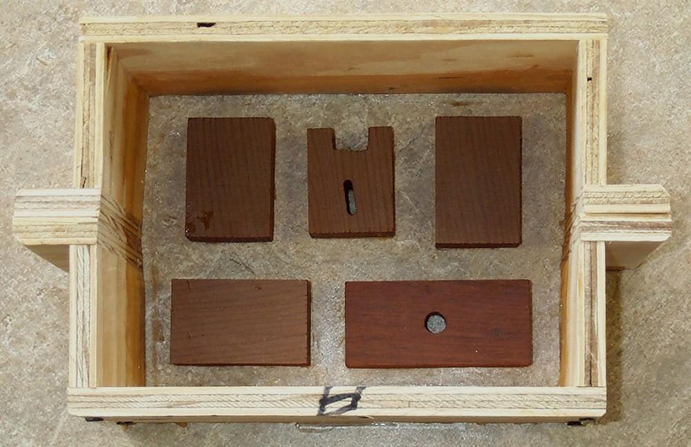
4 Inside of mold Master, mold, and box Cut spacers for one side of the bridge from a single piece of wood (for consistent width). Drill a 3/8 hole in the exact center of the center spacer for the pivot bushing. The drawing shows the shape for the end spacers to allow for an adjustable brass piece to hold the wheels. In the same way as above, make a mold for the spacers and cast two sets of spacers (left and right sides). You could make these from ¾ acrylic and skip the casting step.

5 Spacers Spacers in box

.")
6 Silicone poured over spacers I used Urethane glue (e.g. Gorilla glue) to assemble the sides and spacers. Start by carefully marking the exact center of the bridge sides. Assemble the bridge upside down on a FLAT surface. Use a square to align the two sides. Use a ¼ -1/2 scrap to space one center spacer from the top of the bridge (now on the bottom). Align the other center spacer with the bottom of the bridge (now on the top). Use a 3/8 drill bit to ensure the holes are aligned. Glue and clamp.

7 Create a stack up, glue and clamp center spacers When the glue has set (about 5-6 hours), glue and clamp the next two spacers on each side (these are aligned vertically). When this glue has set, repeat for the next set of spacers. Finally, glue and clamp the two end spacers to the bridge sides. The placement of these from the end of the bridge is somewhat critical. The outside of the spacer should be 7/8 from the ends of the bridge. Build and mount the brass brackets on the end spacers as shown below adjustment will be done later.

8 If you want a walkway on the bridge, construct it from plastic and brass but don t mount it yet. Prime and then spray the bridge flat black with exterior paint. Wait to cut and mount the track until the pit is constructed and the bridge mounted and you can see how close you came to centering everything. Building the pit wall The pit wall is cast in white concrete on a 36 circular piece of ¾ plywood. Mark a centerpoint on the plywood. Use a trammel to draw circles of 15 and 16.5 radii. Cut about 60 pieces of 1x2 lumber 3 long. About every 3 around these two drawn circles, glue with white wood glue one of these pieces standing upright on the inside of the inner circle and on the outside of the outer circle. Cut a piece of 4 wide Aluminum flashing 8.5 ft. long. This will form the inner side of the pit wall. Place an end about 3 from an upright and hot glue the flashing to the upright. Proceed around the circle gluing the flashing to all the uprights. This will give you a smooth, consistent wall. Do likewise with a 9.5 ft. long piece of flashing to make the outer wall of the pit. Use caulking to seal the bottom and ends of the flashing. Now coat the plywood on the bottom of the mold with Vaseline being sure to work it into the joint between the flashing and the plywood to seal it. At several places around the inside of the mold, mark the point 3 1/8 above the plywood base. You will fill to this point.

9 Use travel to lay out circles for pit wall

10 Glue blocks around both circles


11 Outside wall in place sealed with caulking Mold ready for pouring Place the mold on a LEVEL surface shim as needed to achieve this. Dry mix 2 parts sand with one part white or gray Portland cement (depending on the color pit walls you want). Add water
12 to create a slightly soupy mix. Pour into the mold. Use a vibrating sander against the edge of the plywood or in the middle of the circle to get the mix to flow around the circle and remove air bubbles. Keep adding mix and vibrating until you reach the 3 1/8 point all around. It s important that the wall height be uniform all around. Allow this to set for 3-7 days depending on temperature. Use a hammer to break the uprights off and pull off the flashing. If you re ambitious, you can use a hobby grinder to carve the inside of the wall to look like blocks or stones. Building the pit The pit is built on top of a FLAT, LEVEL concrete pad. Excavate a 42 square for the turntable 8-9 deep below track level. The dirt underneath should be packed solid you don t want it settling later. Construct a 3 square (inside) box from lumber with flat, true sides plane the lumber, if necessary (it doesn t have to be square built a round box if you like). Stake this securely so that the top of the box is level and 3 1/8 below track level (the BOTTOM of the ties -- the height of the pit wall). Put about 2 of sand in the bottom for drainage. Cut a piece of ½ hardware cloth about 33 square. Put a 1 layer of concrete over the sand. Put in the hardware cloth and fill the box with concrete. Work it good around the sides to get rid of air pockets. Screed it and work the surface to smooth it. For drainage you want 4-6 holes around the pit. You can use ¼ dia. nails or wood dowels and drill these larger later. You can also use ¾ PVC these won t go through the screening but you can drill through later. Let the concrete cure for 2-5 days depending on the temperature. Remove the form and drill out the holes all the way through the concrete into the sand. Fill the holes with ¼ granite or something similar to allow drainage fines or sand is too small and will plug up. This will give you a flat, level 3+ slab of concrete to build on.

13 Pouring the turntable pad Locate the center of the slab (or where you want the center of the turntable to be as long as it s not too far from the center of the slab). Drill a 3/8 hole in the center for the pivot bushing. Drill this as close to vertical as you can about 2 deep; you don t want to go all the way through. Again with a trammel, draw circles of radii 14 7/8 and 13 ½. The first will be used to align the pit wall and the second to align the ties for the pit rail. Mounting the bridge The purpose of the center shaft and bearing is to locate the turntable, not support any weight. The critical thing here is to make the bearings in the concrete platform and in the bridge as close to vertical as possible. For bearings I found both bronze bearings (expensive) and thick walled brass tubing. A ¼ brass rod will serve as center post. Press a bearing into the top and bottom center spacers in the bridge. If the holes were well aligned when the spacers were glued, you should be able to pass a ¼ rod through both easily. Seal one end of a 1-2 long bearing with a small piece of brass strip. Solder a wire or piece of brass on the other end to be used to pull it back out of the hole.


14 Bearing for center hole Place the bearing into the center hole in the concrete platform. Place the brass rod in the bearing and slip the bridge over it. Use a few 5/16 flat washers to space the bridge up from the bottom of the pit. Without scraping the paint off the bottom off the bridge, swivel it around and ensure it swivels smoothly remaining horizontal. If not, the hole in the concrete is probably not vertical and will need to be drilled out a bit. I like to build tools to make the job easier. Take an unwarped 1 long scrap 2x4. In the middle (lengthwise), about ½ from an edge, drill a ½ hole ½ deep. Drill a ¼ hole all the way though. Use a chisel to break out the 1/2 part of the hole as shown in the photo. This is the escape hole for the wire on the bearing. Push the ¼ rod through the hole (it will be a tight fit) and put into the center bearing. Use a square as shown in the photo to align the rod vertically in two orthogonal dimensions. If you


15 can t get it vertical, you may have to drill out the hole in the concrete a bit. Slowly add sand to the center hole so that the bearing extends from the top of the hole about 1/16. Bearing protrudes 1/16 from concrete Use epoxy to glue the bearing into the hole using the tool to hold it in vertical alignment while the glue sets. When set, add epoxy around the top of the bearing to seal (waterproof) the outside of the bearing in the hole. Vertical alignment of bearing is critical Once the glue sets, slip the rod into the bearing. Put a few 5/16 washers between the bearing and the bridge to keep the bridge from scraping on the concrete. Recheck for smooth rotation. Remove the bridge. Mounting the pit walls and pit rail Measure the diameter of the pit walls at several points. It should be ½ larger than the bridge length. If it s less than ¼ at any point, you ll need to trim the bridge length to get the required clearance. If necessary, trim the same amount from both ends to keep the center in the center.

16 Carefully slide the pit wall off the plywood into position and use the 14 7/8 circle to align it. Double check by measuring the radius to many points on the pit wall. With epoxy glue four of those 1x2 uprights used to cast the wall to the concrete platform to hold the pit wall in place. You may wish to build a box larger than the pit wall and pour concrete around the pit to the level of the top of the pit. Or perhaps just fill the area with ballast. Saw four feet of tie strips to leave about ¼ of tie on the inside of the tie plates. Bend a total of 88 of code 250 rail to 27 1/2 dia. and insert into tie strips with the finished tie end towards the inside (trim the length as it s installed). Place the pit rail around the edge of the pit wall. It s critical that the rail be circular so align the tie ends to the 13 ½ radius circle you drew. Anchor the tie strip with urethane glue. You may need to use screws in a few places or put a shim between a tie end and the pit wall. Try to get it as true to circular as you can. I found it easier to start gluing on the side away from the joints in the rail and work towards the joints. The joint areas needed the screws and shims to force them into position. Slip the bridge over the center post and adjust the wheels on the end of the bridge to ride on the pit rail and give the bridge the same height as the pit wall. First, the pulleys must be mounted to have sufficient play on the #10 bolt to accommodate any out-of-roundness of the pit rail. Slowly rotate the bridge through 360 degrees looking at the pulleys at each end to see if any run out of play at any point. Adjust the bolt out to increase outward play. Add/subtract inside washers to adjust inward play. Too much play will allow the pulleys to ride up and off the rail.


17 Bracket and wheels to ride on the pit rail If necessary, shorten the ¼ vertical shaft so it doesn t protrude above the bushing in the bridge. Glue a scrap of brass to cover the center hole (don t get glue in the hole) and paint it black. Then cut a piece of track equal to the pit diameter plus ½ and anchor it to the top of the bridge using #4 stainless self-tapping screws; this must centered both along length and width. Now you can run your access tracks to your new turntable. I anchored each access track with a screw through the end tie into the pit wall.
18 Electrical connections If you need to power the track on the bridge, I suggest wiring it to the center post bearing and the wheels on the ends. Finishing touches Mount the walkway on the bridge if you built one. Carve and/or paint the pit walls. Glue gravel (fines) on the pit floor. Paint any visible screw heads black. Grease the center pivot rod. Note that every time you replace the bridge you need to check that the pulley wheels are seated on the pit rail properly. If you have tracks to the turntable exactly 180 apart, small errors in construction may cause the tracks at both ends to not be aligned exactly at both rotations of the turntable. You can chamfer the rails (increase gauge slightly at the ends) on the bridge and the entry tracks to help avoid derailments. Build a roundhouse that s a project for another day. Parts list 4x ¼ radius x ¼ wide pulley wheel 4x brass screws 1.25 long 8x brass nuts 8-12x #10 brass flat washers 2x 6-32 brass screws 1.25 long 2x 6-32 brass nuts 2x #6 shake washers 2x #6 lock washers 4x #6 brass flat washers 2x fabricated brass brackets 2 l x w x.060 t 2x brass bushings 3/8 OD x.25 ID x.75 long 1x brass bushing 3/8 OD x.25 ID x long 1x ¼ x 6 long brass rod 8 code 250 rail (Al or NS recommended) 4 code 250 tie strips 2x code 250 rail clamps 4-6x #4 stainless self-tapping screws ½ ¾ long Misc. stainless or brass screws to anchor pit rail and access tracks 36 dia. ¾ plywood round 17 4 aluminum flashing Misc. 1x2 lumber Urethane and epoxy glues If you re going to make your own molds for the bridge, you ll also need:
19 ~6 1x3 lumber ½ plywood 3 x 10 Material to make bridge side master and spacer master Silicone mix Resin mix 3x Wilsonart or Pergo tiles Tools needed Table or radial arm saw Drill press Drill bits 5/32, 13/64 Drill bits wood: ¼, 1/2 Drill bits - masonry: 3/8, ½ Hot glue gun Finish and belt sander Screw drivers, pliers, and wrenches Clamps
Balustrade Systems / Installation Instructions
 A. PARTS AND SUPPLIES NEEDED FOR INSTALLATION Hardware included for each 10 section of rail: 2 3 x 1-1/2 L-brackets 4 1-3/4 x 3/16 Blue hex-head screws for anchoring the L-brackets to the newel cap, column
woodworkersjournal.com MATERIAL LIST
 MATERIAL LIST T x W x L 1 Legs (2) 1 1 2" x 3 1 2" x 36 7 16" 2 End Uprights (2) 1 1 2" x 3 1 2" x 32 1 2" 3 Stringers (4) 1 1 2" x 3 1 2" x 42" 4 Top Cladding, Long (2) 3/4" x 7 1 4" x 65 3 4" 5 Side
Continue gluing the remaining top parts ensuring the angled piece is glued well. Set aside and let dry. See photo below
 Radiator rev 1.1 The SE5a s radiator is one of the most recognized radiators in WW1. It is one of the components that defines the SE5a. The original SE5a has seen multiple radiator designs used during
Building Instructions
 Building Instructions Tools Required Tape measure Straight edge Pencil/pen Jigsaw Table Saw Circular Saw Electric drill 1 Hole saw bit Saw horses/table Protractor Staple gun Caulk gun Paint brush Wrenches
12. Wings, Flaps, Ailerons and Struts
 12. Wings, Flaps, Ailerons and Struts Fit Aileron Hinges Reference: Drawing 20270K2 Photo 12.1 Parts Required: 2007092 Aileron LS 200809N Aileron RS 2001394 Hinge 3/16 A1 (4) 2001694 Hinge Pin (4) PH0059N
Hinge Mortising Jig. One of the make it or break it parts of building a. 6 ShopNotes No. 74
 Hinge Mortising Jig A Mortise for a Hinge. Quick, clean, and accurate that s the only way to describe the mortise you get with a trim router and this hinge mortising jig. One of the make it or break it
Lumber Smith. Assembly Manual. If you are having problems assembling the saw and need assistance, please contact us at:
 Lumber Smith Assembly Manual If you are having problems assembling the saw and need assistance, please contact us at: 804-577-7398 info@lumbersmith.com 1 Step 1 Safety Carefully read the Owners Manual.
 America s leading woodworking authority To download these plans, you will need Adobe Reader installed on your computer. If you want to get a free copy, visit: http://adobe.com/ reader. Having trouble downloading
MODERN PERGOLA INSTALLATION GUIDE. When only the best will do.
 MODERN PERGOLA INSTALLATION GUIDE When only the best will do. TOOLS LIST Drill(s) 3/8" Magnetic Driver (s) 12" Drill Extension #2 Square Drive bit for Drill or Driver Level Tape Measure Hammer Drill if
BUILDING A STORM DOOR
 BUILDING A STORM DOOR BY NEAL BARRETT Illustrations by George Retseck If you're in the market for a storm door, you probably know that there are many styles and models available. However, most of them
Obtained from Omarshauntedtrail.com
 DaveintheGrave's Halloween Props Animated Crawling Skeleton Build a life-size skeleton torso that realistically crawls across the lawn one arm at a time. 1. Motor Base and Linkage Assembly BASE - I used
Plans. Easy-to-Build Full-size Deluxe Murphy Bed Plan. For more plans, tools and hardware visit rockler.com
 Easy-to-Build Full-size Deluxe Murphy Bed Plan Build a full-size Deluxe Murphy Bed complete with decorative molding and matching side cabinets! Plans For more plans, tools and hardware visit rockler.com
Balustrade System Installation - Cambridge & Huntington
 A. PARTS AND SUPPLIES NEEDED FOR INSTALLATION Hardware included for each 10 section of rail: 2 3 x 1-1/2 L-brackets 4 1-3/4 x 3/16 Blue hex-head screws for anchoring the L-brackets to the newel cap, column
Installing your new Bevella Top. L Shaped Countertop with Joints No Finished Ends (Fits Between Four Walls)
") Installing your new Bevella Top L Shaped Countertop with Joints No Finished Ends (Fits Between Four Walls) Bevella RTI Countertops are engineered and manufactured to the highest quality standards, built
Installing your new Bevella Top L Shaped Countertop with Joints No Finished Ends (Fits Between Four Walls) Bevella RTI Countertops are engineered and manufactured to the highest quality standards, built
A WORD ABOUT BRACING PART A - BUILDING A STRAIGHT, PILE BENT, OPEN DECK TRESTLE. Built in Place, Straight
 BUILDING LARGE SCALE TRESTLES You have many options when building a large scale trestle. The choices you make may be based on the prototype you are modeling; the era or industry you are modeling; or, simply
Chapter 18. Interior Doors
 Chapter 18. Interior Doors 18.1 SWINGING DOORS 18.2 SLIDING DOORS 18.3 BIFOLD DOORS Tools needed by volunteers: Hammer Nail apron Tape measure Square Pencil Tools and equipment needed: Extension cords
Gared Pro-S Portable Backstop
 Models: 9616 & 9618 Installation, Operation and Maintenance Instructions Please read all instructions before attempting installation or operation of these units SAVE THESE INSTRUCTIONS FOR FUTURE USE PUBLICATION
Arched. Building an. Passageway. Although my company specializes in high-end jobs
 Building an Arched Passageway All photos by Brian Striegler This straightforward approach combines basic shop methods with simple site joinery to create an elegant frame-and-panel archway by Gary Striegler
Parts List. Description. Installation Instructions
 Page 1 of 7 Parts List Aluminum Coping Hardware Kit 1 pkg Tek screws 1 tek screw nut driver 1 Snap strip removal tool 1 can Touch up spray paint 1 11/64 drill bit 8 pieces 1/8 Gray PVC 4 long 2 boxes Aluminum
Installation Instructions
 edium + Heavy duty READ BEFORE INSTALLING UNIT Preliminary instructions: 1. Check window opening size: the mounting parts furnished with this air conditioner are made to install in a wooden sill double-hung
READ BEFORE INSTALLING UNIT INSTALLATION WARNINGS AND CAUTION
 edium + Heavy duty READ BEFORE INSTALLING UNIT INSTALLATION WARNINGS AND CAUTION Carefully read the installation manual before beginning. Pay attention to danger and safety notices. be exposed: Carefully
CA to each one. You may have to hold the end down while to glue sets or use an accelerator like I did.
 The following information and photographs are what I did to build the kit. Your methods and needs may differ from this which is fine. There is no right or wrong way if you are used to scratch building.
129 KITCHEN BASE CABINET 480
 129 KITCHEN BASE CABINET 480 There are two sorts of kitchen cabinets: base cabinets, which sit on the floor, and wall cabinets. Base cabinets provide both storage space and work surfaces. They often house
Installation Instructions
 For Medium (15-18.5K) + Heavy duty (22-28.5K) Air Conditioner READ BEFORE INSTALLING UNIT To avoid risk of personal injury, property damage, or product damage due to the weight of this device and sharp
S W E RV E RAC K. Simple Security. Simple Stability.
 S W E RV E RAC K Simple Security. Simple Stability. The Swerve Rack is a proven design that provides high security and easy bike parking. The Swerve Rack uses thick pipe construction and the full radius
Chapter 1. Beam and Sill Plates
 Chapter 1. Beam and Sill Plates 1.1 ESTABLISHING SQUARE SILL PLATE CHALK LINES 1.2 INSTALLING TREATED SILL PLATES 1.3 INSTALLING LAMINATE BEAM Tools needed by volunteers: Hammer Nail apron Tape measure
STANDARD CANOPY WORK REPORT B-1
 STANDARD CANOPY WORK REPORT B-1 No. Check Parts / Tools Qty _ Canopy Lock 1 [ ] 6E2-3 Canopy Hinge Block 1 2 [ ] 6E4-5 Canopy Side Frame 2 2 [ ] 6E2-1 Canopy Lock Assembly 1L + 1R 3 [ ] 6E2-4 Rear Lock
WOOD COUNTERTOP INSTALLATION INSTRUCTIONS
 1209 Logan Circle, Atlanta, Georgia 30318 www.craft-art.com (404)352-5625 WOOD COUNTERTOP INSTALLATION INSTRUCTIONS Required Tools and Supplies Cordless Drill Belt Sander with 60 and 80 grit belts. Shur-form
Frameless Inline Door With Return QCI5263
 INSTALLATION INSTRUCTIONS Frameless Inline Door With Return QCI5263 WALL MOUNT HINGES FRAMELESS DOOR / PANEL / RETURN PANEL QCI5263 REV. 0 Page 1 Certified 06/17/2016 Parts List with wall mount hinges
Ford Ranger / Bronco II Set Part # Rev B 5-04
 Ford Ranger / Bronco II Set Part # 21008 Rev B 5-04 Step 1: Prior to Installation: A) Fit: Verify the fit of the flares to vehicle. (Some filing, sanding, or cutting may be necessary to ensure proper fit).
Model 209 Fireback Replacement
 Model 209 Fireback Replacement Please read all the instructions before you begin the procedure. Confirm that you have all the necessary tools and materials. If you have any questions, technical support
CUSTOM SHUTTERS IN-A-BOX
 CUSTOM SHUTTERS IN-A-BOX SHUTTER ASSEMBLE INSTRUCTIONS & INSTALLATION INSTRUCTIONS 1. Inspect the contents of your package. Do not discard the shutter packaging box until you have started painting your
Installation Guidelines
 Page 1 Tools You ll Need 4 ft. Carpenter s level Chalk line (to mark U channel locations) Cordless drill/nut driver Caulking gun Chop saw with a metal cutting blade on it (required to make accurate and
Shed Assembly Instructions
 Shed Kit Contents The shed kit includes all the parts needed to assemble your shed except for tools and fasteners such as screws and nails. The various pieces are pre-cut and many are marked to indicate
ULTIMATE ROUTER TABLE PLANS. By Dan Phalen
 ULTIMATE ROUTER TABLE PLANS By Dan Phalen January 2017 Ultimate Router Table Plans. Copyright 2012-2017 by Daniel Phalen. Published by Creston Hall Publishing Company. All rights reserved. No part of this
Wood Duck Nest Box Design & Assembly Directions
 Wood Duck Nest Box Design & Assembly Directions Instructions, Illustrations & Photos Courtesy of MWDI and Scott Jasion, Harford County Chapter, Ducks Unlimited Side door opening design for easy mounting
SE5a Instrument Board part 2 - rev 1.1
 SE5a Instrument Board part 2 - rev 1.1 Fuel (Petrol) Valve This valve uses two circular name plates, eight brass screws, one black plastic base, copper wire and two black plastic risers. You can pick any
Deck Mount Installation with Bench
 Deck Mount Installation with Bench 1. Mark track with square. 2. Cut tracks with saw. 3. Drill ¼ hole (if needed.) 4. Countersink track. 5. Countersink all track 6. File all track ends. ends. 7. Lay out
Giraud Tool Company, Inc.
 Motor Upgrade for Gracey Trimmer This package is intended to allow the user to upgrade their Gracey trimmer with a higher rpm motor and convenience features not found in the production offering. This upgrade
Swerve Rack CUSTOM RACKS AVAILABLE
 CUSTOM RACKS AVAILABLE Swerve Rack The design of the Swerve mirrors the bike frame, thus providing superior bike support while making it easy to secure both the bike frame and wheel with a standard u-lock.
Making a Cement Upper Molding Surface for Compression Molding of Shape&Roll Prosthetic Foot Cores
 Making a Cement Upper Molding Surface for Compression Molding of Shape&Roll Prosthetic Foot Cores Andrew Hansen, PhD Steven Steer, MS Kerice Tucker Elizabeth Klodd Craig Heckathorne, MS Northwestern University
Spiral Slide
 IMPORTANT Page 1 PLEASE READ THESE INSTRUCTIONS BEFORE COMMENCING ASSEMBLY. All equipment must be installed in accordance with these instructions. Check your shipment against Bill of Lading and Parts list.
136 PLYWOOD DESK 522
 136 PLYWOOD DESK 522 Simple in design and inexpensive, this plywood desk is made from a single 4- x 8-foot panel. Plywood is available with many hardwood veneers; it can also be covered with plastic laminate,
the wire, less is better. And make sure the bends on each truss wire are in line with the other. See the next photo.
 The following information and photographs are what I did to build the kit. Your methods and needs may differ from this which is fine. There is no right or wrong way if you are used to scratch building.
Clocking a TD-04 Turbo Compressor Housing. Appendix A : AWIC Silicone and Tubing Fitting
 Clocking a TD-04 Turbo Compressor Housing Appendix A : AWIC Silicone and Tubing Fitting Revision A: 7-13-2015 Tools: Metric Sockets (10, 12, 14, 17mm) 5mm Hex Key Large Internal Snap Ring Pliers 3/8 Socket
Practical Scrap Metal Small Arms Vol.10 By Professor Parabellum
 Practical Scrap Metal Small Arms Vol.10 By Professor Parabellum Introduction The 9mm submachine gun design described here is extremely basic and can be put together using very limited tools and materials.
Chapter 17 - Porch Trim
 Chapter 17 - Porch Trim Contents Chapter 17 - Porch Trim... 17-1 Timing & Prerequisites... 17-2 Trim on Porch Beams (Volunteer)... 17-4 Smart Trim on the Bottom of the Beam... 17-4 Smart Trim on the Inside
Fig. 2 DORMA-Glas Stand/Issue 02/03 Seite/Page 1/7
 FSW Installation instructions Track rail 75 x 72 mm 1. Ceiling substructure and installation of the track rail (Fig. 1): The track rail must be bolted over its entire length (including the stacking track
Traditional Undermount: S Method (Undermount):
:") TOOLS REQUIRED 15.1 TOOLS REQUIRED The installation of Corian shape product must be a precise and exacting process to ensure that a good fit is always created. Using the correct tools is essential. In
TOOLS REQUIRED 15.1 TOOLS REQUIRED The installation of Corian shape product must be a precise and exacting process to ensure that a good fit is always created. Using the correct tools is essential. In
U. M. ARMY Texas Conference. Wheel Chair Ramp Manual
 U. M. ARMY Texas Conference Wheel Chair Ramp Manual June 2014 U. M. ARMY Texas Conference Building & Repair Tips Wheelchair Ramps Complete a site survey to determine the design and layout of the ramp.
Mobile Weapons Storage System Specifications
 Mobile Weapons Storage System Specifications Whatever your weapon storage needs, Hi-Density s customized Weapons Storage System will be designed to fit your unique specifications. We recognize that security
7141 & NATIONAL POLE VAULT STANDARDS SPECIFICATIONS
 SPECIFICATIONS Specifications: This standard has a clamping system and a handle added for ease of operation. The clamping system is above the base pad protectors when in the lowest position and the tightening
Installation Instructions for. Before You Begin TOOLS REQUIRED
 Composite Railing System STEP-BY-STEP Installation Instructions for Spectrum Composite Railing Virtually maintenance free 20-year warranty EverNew Spectrum Railing system is designed to work with a number
Installation Instructions
 Supafold Slide Aside System Three Fold Room Divider Installation Instructions Distinctive Doors Ltd Supafold Slide Aside Internal Folding System IMPORTANT: Before proceeding with the installation, and
Durable Outdoor Table
 54 F I N E W O O D W O R K I N G Durable Outdoor Table Ipé table will seat six and weather many seasons B Y D A V I D B E D R O S I A N Last summer brought a new pool to our backyard. With it came more
10x10 Trellis Pergola
 0x0 Trellis Pergola ASSEMBLY GUIDE Ver.-007 Table of Contents PAGE 0x0 Trellis Pergola Introduction & Overview...................................................... Pergola Materials Overview..............................................................
WOOD TOY NEWS. July 23, 2013 Tuesday
 WOOD TOY NEWS Make your own perfect turntable for spray painting toys with these useful tips. And it s fast, fun and easy to build! by Imants Udris Watch the video on our website at : http://www.toymakingplans.com/website/how-to/
10. Wing prep and subassembly
 Date Section Objective: Construct and fabricate the sub-assemblies of the wing panel. Required Parts: Wing left 11gal PN104-300, Wing right 1gal PN104-400, Wing left 15 gal option PN104-322, Wing right
Horizontal Cable Systems
 ALUMINUM RAILING INSTALLATION INSTRUCTIONS v2012 orizontal Cable Systems 1) Check Contents Of Packages: Verify that all parts have arrived and that they match the packing list. 1A) Coastal applications:
H O O P RAC K. Simple Security
 H O O P RAC K Simple Security The Hoop Rack is a proven design that provides high security and easy bike parking. The Hoop Rack uses thick pipe construction and the full radius of the bend makes the Hoop
Woodline USA Woodline Spacer Fence System
 Woodline USA Woodline Spacer Fence System MADE IN THE USA Includes: (1) ¼ Spacer Fence (1) 3/8 Spacer Fence (1) ½ Spacer Fence (1) Hardware Package (1) 3 Piece Brass bar set (2) Setup Blocks Visit Us Online
10x10 Trellis Pergola
 0x0 Trellis Pergola ASSEMBLY GUIDE Ver.0-7 Table of Contents PAGE Introduction & Overview...................................................... Pergola Materials Overview..............................................................
-1- Coach Instructions.
 -1- Coach Instructions. Insert the bogie pivot pins through the bottom of the coach body ensuring the dimples fit into the recesses. Glue the.06 x.25 short strips each side of the pivot head, bridge the
CENTER WING SECTION (CWS) WORK REPORT
 WORK REPORT") CENTER WING SECTION (CWS) WORK REPORT No. Check Parts / Description Qty PHASE 1: Preparations 1 [ ] 6V1-3 Rear ribs 2R & 2L 1 [ ] L Angle 6 2 [ ] 6V2-1 Rear Ribs.032 2R & 2L 2 [ ] 6V5-1 Gear Rib Doubler
CENTER WING SECTION (CWS) WORK REPORT No. Check Parts / Description Qty PHASE 1: Preparations 1 [ ] 6V1-3 Rear ribs 2R & 2L 1 [ ] L Angle 6 2 [ ] 6V2-1 Rear Ribs.032 2R & 2L 2 [ ] 6V5-1 Gear Rib Doubler
Bi-Pass And Bi-Fold Sliders
 Bi-Passs and Bi-Fold Sliders Installation Guide Bi-Pass And Bi-Fold Sliders Tools required: Hand Drill Counter Sink Drill BitSet #8 Philips Screw Driver Measuring Tape Level What s Included: Panels with
Downtown Rack. Custom logo option available
 Custom logo option available Downtown Rack The Downtown Rack uses thick, square-tube construction that can t be cut with a pipe cutter. The extended width of the Downtown Rack makes for easy bike parking
Bumper Sign INSTALLATION INSTRUCTIONS
 Bumper Sign INSTALLATION INSTRUCTIONS BUMPERSIGN TOOL CHECKLIST SDS MAX Rotary Hammer Drill Marker/Pencil SDS MAX 1 Carbide Drill Bit Tape Measure Torque Wrench with ½ Drive Power Source Vacuum ½ Drive
Kid-powered "squaris" wheel
 Kid-powered "squaris" wheel DESIGNED By ROBERT WOOLSON DUBBED A "SQUARIS WHEEL" by its designer because of its square wheel, this pint-sized backyard version of its big brother, the ferris wheel, will
The Q Frame PROJECT. a picture frame with secrets created exclusively for the Router Forum
 The Q Frame PROJECT a picture frame with secrets created exclusively for the Router Forum 007 OR RELEASE FPLANS APPROVED The Q Frame: Project Overview LIST OF MATERIALS Frame Sides & Face 3/4 x 5 1/2 x
Hydraulic Clamp Carrier. Installation & Operation Manual
 Hydraulic Clamp Carrier Installation & Operation Manual Hydraulic Clamp Carrier Installation & Operation Manual Quick Machinery Company 8272 Peninsula Drive Kelseyville, CA 95451 phone: (707) 272-6719
Omarshauntedtrail.com. Obtained from. Merlin's Wall Sconce.
 http://hauntershangout.com/home/wallsconce.asp Plaque Construction Merlin's Wall Sconce Warning: This project uses Electricity! Build at your own risk. Not for children to build. Ever been to a haunt and
Biomass Briquette Mold
 Biomass Briquette Mold Drawings and Assembly Compendium Round, Square, Stick, Cube & Chunk By Lee Hite and Dr. Zan Smith Published March 2012 Updated 8/3/2017 All Rights Reserved www.leehite.org Page 1
Building Tips This model can be built using the following types of adhesives:
 Page 1 Building Tips This model can be built using the following types of adhesives: Epoxy (with or without microballons) Odorless cyanoacrylate (CA) with accelerator UHU Creativ for Styrofoam (or UHU
Kitchen Step Stool. Premium Plan. In this plan you ll find: America s leading woodworking authority
 America s leading woodworking authority Premium Plan In this plan you ll find: Step-by-step construction instruction. A complete bill of materials. Construction drawings and related photos. Tips to help
PRIME SHOWER ENCLOSURE INSTALLATION INSTRUCTIONS
 PRIME SHOWER ENCLOSURE INSTALLATION INSTRUCTIONS IMPORTANT DreamLine reserves the right to alter, modify or redesign products at any time without prior notice. For the latest up-to-date technical drawings,
Kentucky 4H Wood Science Plans Notebook. Plans Level 4
 Kentucky 4H Wood Science Plans Notebook Plans Level 4 MATERIALS NEEDED: Note: 1" wood may be 3/4" thick and 2" x 2" may be 1 1/2" x 1 1/2" 2 pieces wood 1 x 3 x 17 1 piece wood 1 x 3 x 14 3/4" 2 pieces
Tools and Tips: ( 1 )
") Tools and Tips: As you build instructions will show in my many picture manual how to assemble. You can use your own methods as you desire, my results are very good. A smooth, flat work surface is very
Tools and Tips: As you build instructions will show in my many picture manual how to assemble. You can use your own methods as you desire, my results are very good. A smooth, flat work surface is very
H O O P RAC K. Simple Security
 H O O P RAC K Simple Security The Hoop Rack is a proven design that provides high security and easy bike parking. The Hoop Rack uses thick pipe construction and the full radius of the bend makes the Hoop
INSTALLATION INSTRUCTIONS. UNIT No. 160/760 THIN-LINE SHOWER ENCLOSURE
 INSTALLATION INSTRUCTIONS UNIT No. 160/760 THIN-LINE SHOWER ENCLOSURE QCI0011 Rev. 0 Page 1of 10 Certified 10/18/2006 MAINTENANCE: Two primary materials are used to manufacture your new Basco enclosure;
INSTALLATION INSTRUCTIONS
 INSTALLATION INSTRUCTIONS BUILDERS CHOICE FRAMED Shower Height Swing Door Model: L533 Rev. 09.03.13 MAINTENANCE: Two primary materials are used to manufacture your new Aquatic enclosure; tempered glass
Closet System Installation Manual
 Closet System Manual Thank you For choosing our Custom Closet Collection to fit all your needs Closets come fully assembled to make your project an enjoyable and satisfying experience. With quality Custom
Hatchback Wing Riser Kit
 Hatchback Wing Riser Kit 2015-06-11 Thank you for purchasing this PERRIN product for your car! Installation of this product should only be performed by persons experienced with installation of aftermarket
Retractable Screen Installation Instructions For Vinyl and Aluminum Clad and Wood In-Swing Hinged Doors (See separate instructions for sliding doors)
") Retractable Screen Installation Instructions For Vinyl and Aluminum Clad and Wood In-Swing Hinged Doors (See separate instructions for sliding doors) IMPORTANT: Please read before you begin. Table of Contents
Retractable Screen Installation Instructions For Vinyl and Aluminum Clad and Wood In-Swing Hinged Doors (See separate instructions for sliding doors) IMPORTANT: Please read before you begin. Table of Contents
Installation Instructions Universal Crossmember Kit - 60 Track Width BEFORE Measure Twice, Weld Once! II
 Installation Instructions Universal Crossmember Kit - 60 Track Width Please read these instructions completely BEFORE starting your installation. Remember the basic rule for a successful installation:
Set Part # Rev
 Set Part # 21007 Rev-3 06-06-11 Step 1: Prior to Installation: A) Bushwacker only approves installing the flares according to these written instructions with the hardware provided. WARNING: Failure to
UNIT No FRAMELESS PIVOT SHOWER DOOR
 INSTALLATION INSTRUCTIONS UNIT No. 3600 FRAMELESS PIVOT SHOWER DOOR NEED INSTALLATION HELP? Call 1-800-45-BASCO (452-2726) Monday - Friday 8:00 A.M. - 4:30 P.M. Eastern Time QCI0020 Rev. 3 Page 1 of 8
Project: Trebuchet Overview: This medieval launcher would reek. Materials: 3/4 plywood, 2 of 5/8 threaded. Minimum Cutting Area: 2 sheets of plywood
 Project: Trebuchet Overview: This medieval launcher would reek havoc on enemies castles. However, the modern day conversion using 20lbs of weight will easily through a tennis ball the length of a gymnasium.
Sliding Glass Door Assembly and Installation Guide
 Sliding Glass Door Assembly and Installation Guide Index Door System Components and Hardware The following components are needed to complete the installation of your Sliding Patio Door unit. Check all
Horizontal Cable Systems
 ALUMINUM RAILING INSTALLATION INSTRUCTIONS Horizontal Cable Systems 1) Check Contents Of Packages: Verify that all parts have arrived and that they match the packing list. 1A) Coastal applications: Confirm
Darjeeling Coach 4-Wheel First/Second Class
 Darjeeling Coach 4-Wheel First/Second Class Introduction This kit was designed in 16mm scale from early Darjeeling drawings and photographs. It uses brass castings available from Brandbright. The instructions
PFW 6875 Installation Guide Installationsanleitung, Guía de Instalacíon, Guida de Installazione, Guide d Installation, Installatie gids
 Maximum Flat Panel Weight: 160 lb. / 72.57 kg. Included Components Wall Mount (Qty 1) Extension Brackets (Qty 2) Bracket (Qty 1 Pair) 5/16 Flat Washers (Qty 4) Universal Spacers (Qty 8) M5 Allen Driver
Frameless Inline Door QCI5248
 INSTALLATION INSTRUCTIONS Frameless Inline Door QCI5248 FRAMELESS PANEL / DOOR / PANEL QCI5248 REV. 0 Page 1 Certified 06/16/2016 Parts List with glass to glass hinges *Quantities may vary. **Support Bar
TOLL FREE:(888) FAX:(941) ASSEMBLY of ProTEC CONCRETE STRUCTURAL INSULATED PANEL
 FAX:(941) ASSEMBLY of ProTEC CONCRETE STRUCTURAL INSULATED PANEL") ASSEMBLY of ProTEC CONCRETE STRUCTURAL INSULATED PANEL The ProTEC panels are manufactured with grooves on all four sides to accept the steel components. This grooving applies to the regular panel whose
ASSEMBLY of ProTEC CONCRETE STRUCTURAL INSULATED PANEL The ProTEC panels are manufactured with grooves on all four sides to accept the steel components. This grooving applies to the regular panel whose
Installation Instructions for FC2 & FC15 Forward Controls for the Super Magna
 Installation Instructions for FC2 & FC15 Forward Controls for the Super Magna It is highly recommended that you use a thread lock compound such as Loctite brand on all threads to keep them from vibrating
Copyright 1998 KDE Technologies
 Modular Computer Corner Desk Unit Copyright 1998 KDE Technologies http://members.tripod.com/~kdetech/ 1. Introduction 2. Plans Sheet one - Isometric Sheet two - Top Detail / Corner Unit Sheet three - Leg
MM540 Installation Instructions IMPORTANT SAFETY INSTRUCTIONS - SAVE THESE INSTRUCTIONS
 MM50 Installation Instructions IMPORTANT SAFETY INSTRUCTIONS - SAVE THESE INSTRUCTIONS Please read this entire manual before you begin. Do not unpack any contents until you verify all requirements on PAGE.
Chapter 9. Windows and Exterior Doors
 Chapter 9. Windows and Exterior Doors 9.1 INSTALLING WINDOWS 9.2 INSTALLING EXTERIOR HOUSE DOORS 9.3 INSTALLING SHED DOOR 9.4 INSTALLING EGRESS COMPONENTS Tools needed by volunteers: Hammer Nail apron
Cabinet is 90% assembled, all you need to do is to attach the legs, lay the glass top on the cabinet, connect the faucet, drains & ptrap.
 Things you might need for the installation: vessel sink, plumber's putty(home depot), liquid nails(home depot), Bucket silicone caulk(home depot), Putty knife Plumber's putty Pipe wrench Channel-lock pliers
Fold-A-Way Patio Door ASSEMBLY & INSTALLATION GUIDE
 Fold-A-Way Patio Door ASSEMBLY & INSTALLATION GUIDE This instruction guide provides the minimum recommended procedures to correctly prepare the rough opening, install a fold-a-way patio door unit and apply
Clock 35 - Toyland. Construction instructions for Clock 35
 This clock has been designed for children, it is a stand-alone unit and can be positioned on a shelf or cabinet out of the reach of very young hands who may be tempted to touch. The clock is shown in two