Prof. Steven S. Saliterman Introductory Medical Device Prototyping
|
|
|
- Cody Clarke
- 5 years ago
- Views:
Transcription

1 Introductory Medical Device Prototyping Department of Biomedical Engineering, University of Minnesota

2 Images courtesy of Haas
3 You must complete safety instruction before using tools and equipment in the Medical Device Center, ME Student Shop and CSE Workshops. All machinery can be dangerous. You must have a trained individual instruct you first when using unfamiliar equipment. Only authorized and trained individuals may operate CNC equipment. Code examples shown are for illustration purposes only, and are not meant for operation or programming actual equipment. They may be incomplete or contain errors. Always abide by shop safety instructions and never engage in horseplay. Remember to wear OSHA approved eye protection in the shop, short sleeves, leather or steel toed shoes, and secure long hair, avoid loose clothing, and take off rings, watches and bracelets when using power equipment. These slides are part of the Introductory Medical Device Prototyping course at the University of Minnesota, and are not meant for any other purpose. Formal training in Haas is available from Productivity, Inc.
4 X is the back to front motion, with the part X0 being coincident with the Z axis. Determines diameter. Z is the spindle axis, and the part Z0 is normally the front finished face. Determines location of faces, shoulders and grooves. Home reference position movement at startup to extreme limits. A zero-return at POWER/STARTUP. This is the machine zero. We use a floating zero referred to as the part zero or part origin. We touch off the face and diameter, and store the offset from the machine zero in X and Z register of the Tool Offsets Page. (Not the same as mill which uses G54!)
5 Image courtesy of Productivity and Haas
, hence a X1.0 will be moving the machine along the x-axis 0.5 in the positive direction.")
6 Normally most of the X values are going to be positive in a part program. A negative X will occur only if you face a part past the centerline. X values are in diameters (not radius), hence a X1.0 will be moving the machine along the x-axis 0.5 in the positive direction. Z values will tend to be negative since zero is at the face. (Max. -1 travel beyond the spindle zero.)
7 Absolute positioning: X and Z codes are based on the Zero point of the part. If a diameter of inches is needed, you input X If you are facing a shoulder 0.3 back from the face of the part, Z is input. Incremental positioning: U and W based on current position of the machine. So a change of U would be a smaller diameter of 0.5 from where the machine is presently at. A grooving tool moving back ¾ behind the previous groove would be input as W Also called point to point. Simultaneous moves are possible e.g. G01 X2.000 W-.25 Moves X in absolute and Z in incremental at the same time.

8
9 A block is a series of words on a single line ended with a ; also known as the end-of-block (EOB) symbol. Leading zeros and + signs are not needed. Modal commands with G, X, Z,F, S, T and M need not be repeated in the following blocks unless a different word or change of value is needed. Only one M code at the end of the block is permitted. Preparatory G codes make the tool do specific operations. M codes cause action to occur at the end of the block. Always executed last. N1-N9999 are optional sequence (line) numbers especially useful in macro subroutine. Programs begin and end with %. The second line is the title of the program. Format is O followed by 5 digits. Enter comments by enclosing in parenthesis. A forward slash / denotes an optional block. BLOCK DELETE will skip these lines when running.
10 A Forth Axis B Linear B-axis motion C Fifth axis rotary motion D Canned cycle data E Feed rate F Feed rate G Type of operation, 0 to 255. G0x are non-modal, referring only to that block. I, J, K Canned cycle and circular optional data L Loop count for repeated cycles. M Control miscellaneous functions N Line number O Program number (name) Oxxxxx P Delay time Q Canned cycle optional data. R S T U V W X Y Z Canned cycle and circular optional data Spindle speed ( ) No decimals allowed. Tool selection Txxyy, where xx is tool location with respect to the turret position and yy selects the tool offset (1-50). Incremental X axis motion Optional macro parameter Incremental Z axis motion Linear X axis motion Linear Y-axis motion Linear Z-axis motion
11 M00 M03 M04 M05 M08 M09 M10 M11 M21 M22 M23 Program stop (spindle, axes, coolant) Start spindle clockwise Spindle counterclockwise Spindle stop Coolant on Coolant off Clamp spindle chuck Unclamp spindle chuck Tailstock forward Reverse tailstock Thread chamfer (G76 or G92) M24 Thread chamfer off M30 Program end and rewind M41 Low gear M42 High gear M85 Automatic door open M86 Automatic door close M88 High pressure coolant off M97 Local sub-program call (P or L) M98 Sub-program call (P or L) M99 Return for subprogram or loop
12 On power up the machine will go to part zero entered into G54 from prior probing. Automatic G Codes G00 G18 G40 G54 G64 G97 G99 Rapid traverse X, Y circular plane section Cutter compensation cancel Work coordinate Zero #1 (1 of 26 available) Exact stop cancel Constant surface speed cancel Feed per revolution Safety block used in mill generally not needed. G18 G20 G40 G54 G80 G97 G99
13 G28; (Rapid all axis machine zero) G53 G00 X-3. Z-4.; (Safe locate tool change turret) T101; (Indexes turret to tool) G50 S2000; (Spindle speed max. rpm) G97 S1146 M03; (Cancel surface speed mode; spindle speed; clockwise; rpm) G54 G00 X1.5 Z.02 M08; (Rapid movement to start X, Z; coolant on) G96 S450; (Constant surface speed; surface feet per minute (SFM)) G00 Z1. M09; (Move from part. coolant off) G28; (Rapids to machine home) G53 G00 X-3. Z-4. T0; (Back to tool change location) M30; (End of program. Stop spindle, turn off coolant, cancel tool length offsets)
14 M03 Spindle Forward M04 Spindle Reverse M05 Spindle Stop G50 Maximum spindle speed (RPM - revolutions per min.) G96 Constant surface speed ON (SFM), Tool speed increases automatically as diameter decreases. SFM = x DDDDDDDD x RRR G97 Constant surface speed OFF (DEFAULT) & RPM ON, RPM = 3.82 x SSS DDDDDDDD G98 Feed (inches) per minute, IPM = Current RPM x IPR G99 Feed (inches) per revolution(default), IRP = IPM/Current RPM

15 A move from point A to B can be done by positioning with absolute, incremental or both.
16 Straight line (linear) point to point motion. Both X and Z axis start and stop at the same time. Specified feed rate (IPR) is maintained along the line. May be made in ABSOLUTE or INCREMENTAL commands. Optional ways of programming: Back-off diameter Machine home Part zero
17 X Absolute arc end point. G02 Y Absolute arc end point. U Incremental arc end point. W Incremental arc end point. I Distance from start poin to arc center X axis. K Distance from start poin to arc center Z axis. R Radius of circle (if I and K not used). F Feed rate (IPR).
18 or -R For circular path over 180 degrees.
 Z-1. (feeds to start of arc) G02 X5. Z-2.5 R1.5 (cuts arc) G01 X6.")
19 G00 X0. Z.1 (rapids to X0 Z.1) G01 Z0. F.012 (feeds to face) X2. (feeds to x axis 2 dia.) Z-1. (feeds to start of arc) G02 X5. Z-2.5 R1.5 (cuts arc) G01 X6.0 (moves out of way)
20 k=0... i=1. I = Distance from start point to arc center X axis = 1 K = Distance from start point to arc center Z axis =
21 b a I = Distance from start point to arc center X axis =.707 K = Distance from start point to arc center Z axis = 0 Xa = x ( ) = Za = = Xb = Zb = 2.5
22 An external radius (chamfer) has the Tool Nose Radius (TNR) added to it. Part An internal radius (fillet) has the Tool Nose Radius subtracted from it. Part
23 External Radius Calculation (Add the Tool Tip Nose Radius) If a radius of.25 is required on the external corner of a part and the tool nose radius is.031 the programmed radius will be: =.281 If the radius is on a 1.0 diameter and at the ZO face of the part the program will follow the example below: G1 X0 Z0 Start of program G1 X (281 X 2) =.438 G3 X1.0 Z-.281 R.281 Move to the X and Z axis end point G1 Z-? Next axis parallel move Internal Radius Calculation (Subtract the Tool Nose Radius) If a radius of.25 is required on the internal corner of a part and the tool nose radius is.031 the programmed radius will be: =.219 If the radius is on a 1.0 diameter and at the ZO face of the part the program will follow the example below: G1 X1. Z0 G1 Z-.781 G2 X Z-1. R.219 G1X-? Note: When calculating the end points in a part program you must double the X axis calculation to allow for both sides of the part.
24 G01 Z0. F0.01 X.948 F.006 (1.24-2R 1 ) G03 X1.25 Z-.151 R.151 (0 - R 1 ) G01 Z-.921 (1.13-R 2 ) G02 X1.668 Z-1.13 R.20 (1.25+2R 2 ) G01 X2.218 (3-2R 3 ) G03 X3. Z R.391 ( R 3 ) G01 Z G00 U.01 Z1.0 G28 Lathe tool has a.031 TNR R 1 = =.151 R 2 = =.209 R 3 = =.391
. 3. Published Xc values are diametric and do not need to be multiplied by 2. 4. You will need to subtract Xc and add Zc.")
25 1. When you chamfer (cut an angle) the cutting tip is not the same as where you touched off the tip. The tool was touched off at the red dots, but begins cutting the diagonal at the green dots. 2. The offsets depend on the cut angle and tool nose radius (either 0.31 or.0156). 3. Published Xc values are diametric and do not need to be multiplied by You will need to subtract Xc and add Zc. Y C2 offset.. X C2 offset Y C1 offset.. X C1 offset
26 Example offsets of various angles and tool nose radii:
27 O00055 (LINEAR INTERPOLATION "WITHOUT" CUTTER COMP.) N1 G53 G00 X0. Z0. T0 N2 T101 (O.D. TURNING TOOL.031 TNR) N3 G97 S1450 M03 N4 G54 G00 X0.85 Z0.1 M08 N5 Z0. N6 G01 X-.062 F0.01 (Face down end of part) N7 G00 X.7134 Z0.02 (Rapid to start point of angle subtracting X compensation value: ) N8 G01 Z0. F0.006 (Feed into face) N9 X1.250 Z (Feed up angle adding Z compensation amount: ) N10 Z (Feed to angle adding Z compensation amount) N11 X Z (Feed up to angle subtracting X compensation amount) N12 X (Feed up to angle subtracting X compensation amount) N13 X3.0 Z (Feed up angle adding Z compensation amount) N14 Z (Feed to finish to end in Z axis) N15 G00 U-0.01 Z1.0 M09 N16 G53 G00 X0. Z0. T0 N17 M30 Offset.031TNR/45 degree is: Xc =.0366, Zc =.0183
28 1) Approach Moves and Departure Moves 2) Tool Geometry and Wear Offsets When setting up the tools for a part program, zero any Tool Geometry, Tool Wear, and Work Zero offsets that remain from an earlier job. Then you must touch off and enter the tool geometry (distance from machine home to part zero) length offsets for each tool being used. 3) Tool Nose Radius Geometry Select a standard insert (with a defined radius) that will be used for each tool that is using tool nose compensation. Enter the tool nose radius of each compensated tool in the TOOL GEOMETRY offset display under RADIUS. 4) Tool Tip Direction Input the tool tip direction, in the TOOL GEOMETRY offset display under TIP, for each tool that is using tool nose compensation, G41 or G42. 5) Test Run Compensation Geometry Run the program in graphics mode and correct any tool nose compensation geometry problems that may occur. A problem can be detected in two ways: either an alarm will be generated indicating compensation interference, or you will see the incorrect geometry generated and seen in graphics mode. 6) Run and Inspect Part First

29 Program an approach move for each tool path that needs tool nose compensation and determine if G41 or G42 is to be used. Be sure there is a departure move for each compensated tool path by using a G40 command to cancel tool nose compensation. At the end of the departure move the machine position is not compensated.


30 G41 will select tool nose compensation left; that is, the tool is programmed to the left of a tool path part line, to compensate for the tool tip radius. A tool offset must be selected with a Tnnxx code, where xx corresponds to the offsets that are to be used for the nn tool turret location. G42 will select tool nose compensation right; that is, the tool is programmed to the right of a tool path part line, to compensate for the tool tip radius. A tool offset must be selected with a Tnnxx code, where xx corresponds to the offsets that are to be used for the nn tool turret location. G40 Turn cutter compensation off.
 N8 G01 X0.5 R-0.05 N9 G01 Z-0.5 N10 G01 X0.75 R-0.05 N11 G01 Z-1.0 R0.05 (R is to a positive X axis) N12 G01 X1.25 R-0.05 (R- is to a negative Z axis) N13 G01 Z-1.")
31 O00042 (Linear G01 with Radius using R) N1 G53 G00 X0. Z0. T0 N2 T101 (O.D. TOOL x.031 TNR) N3 G50 S3000 N4 G97 S3000 M03 N5 G54 G00 X0.3 Z0.1 M08 N6 G96 S390 N7 G42 G01 Z0. F0.01 (Tool nose compensation right) N8 G01 X0.5 R-0.05 N9 G01 Z-0.5 N10 G01 X0.75 R-0.05 N11 G01 Z-1.0 R0.05 (R is to a positive X axis) N12 G01 X1.25 R-0.05 (R- is to a negative Z axis) N13 G01 Z-1.5 N14 G40 G00 U0.01 Z0.1 M09 (cancel tool nose comp) N15 G53 G00 X0. Z0. T0 N16 M30
32 1. R+ is to machine a radius into the plus direction on an axis. R- is to machine a radius into the minus direction on an axis. 2. The linear G01 block must be a single X(U) or Z(W) move with an R that is perpendicular to the previous move for corner rounding. 3. When using R for corner rounding, do not use I, K, or A. 4. This Radius (R) command is not supported in any of the roughing passes of a G71 or G72 canned cycles. The last pass of the G71 and G72 will be executed with the radius defined with R in the G01 command. 5. A G70 or G73 will support this type of radius command. 6. The + or - sign define the direction of the axis your moving into at the end of the arc move.
 N9 G01 Z-0.5 N10 G01 X0.75 K-0.05 (X into Z, right of tool) N11 G01 Z-1.0 I0.05 (Z into X, up) N12 G01 X1.25 K-0.")
33 O00043 (Linear G01 with 45 Degree Chamfer using I or K) N1 G53 G00 X0. Z0. T0 N2 T101 (O.D. TOOL x.031 TNR) N3 G50 S3000 N4 G97 S3000 M03 N5 G54 G00 X0.3 Z0.1 M08 N6 G96 S390 N7 G42 G01 Z0. F0.01 N8 G01 X0.5 K-0.05 (face X into Z, right hand) N9 G01 Z-0.5 N10 G01 X0.75 K-0.05 (X into Z, right of tool) N11 G01 Z-1.0 I0.05 (Z into X, up) N12 G01 X1.25 K-0.05 (X into Z, right to tool) N13 G01 Z-1.5 N14 G40 G00 U0.01 Z0.1 M09 N15 G53 G00 X0. Z0. T0 N16 M30
34 1. I is for the 45-degree chamfer size from Z into X. I+ is up, I- is down into the X axis. 2. K is for the 45-degree chamfer size from X into Z. K- is left, K+ is right into the Z axis. 3. The linear G01 block must be a single X(U) or Z(W) move with an I or K that is perpendicular to the previous move for chamfering. 4. When using I or K for chamfering, do not use A or R. This chamfer (I,K) command is not supported in any of the roughing passes of a G71 or G72 canned cycles. The last pass of the G71 and G72 will be executed with the chamfer defined with I and K in the G01 command. 5. A G70 or G73 will support this type of chamfer command. 6. The + or - sign defines the direction of the axis your moving into at the end of chamfer move.
 N9 G01 X1.5 A170. (10 Degree Angle using A) N10 Z-0.5 N11 G40 G00 U0.01 Z0.1 M09 N12 G53 G00 X0.")
35 O00044 (Linear G01 Chamfer 10 Degree Angle using A) N1 G53 G00 X0. Z0. T0 N2 T101 (O.D. TOOL x.031 TNR) N3 G50 S2800 N4 G97 S1490 M03 N5 G54 G00 X1.25 Z0.1 M08 N6 G96 S390 N7 G42 G01 Z0. F0.01 N8 G01 X1.375 (Start point) N9 G01 X1.5 A170. (10 Degree Angle using A) N10 Z-0.5 N11 G40 G00 U0.01 Z0.1 M09 N12 G53 G00 X0. Z0. T0 N13 M30
36 1. The linear G01 block must be a single X(U) or Z(W) move that is perpendicular to the previous move with an A to do a specific angle. 2. When using A for an angle, do not use I, K or R. 3. This angle (A) command is not supported in any of the roughing passes of a G71 or G72 canned cycles, though the last pass in the G71 and G72 will be executed with the angle defined with A in the G01 command. 4. A G70 or G73 will support this type of chamfer command. 5. You can use a minus value to define an angle clockwise from three o clock: A-30. = A150. and A-45. = A Be sure to enter in a decimal point for angles.
37 G70 Finishing G71 O.D./I.D. Stock Removal (roughing) G72 End Face Stock Removal (not recommended) G73 Irregular Path Stock G74 End Face Grooving G75 O.D./I.D. Grooving G76 O.D./I.D. Thread Cutting Cycle, Multiple Pass G90 O.D./I.D. Turning Cycle G92 Thread Cutting Cycle G94 End Face Cutting Cycle Modal
38 The G70 Finishing cycle can be used to finish cut paths that are defined and roughed out with stock removal cycles G71, G72 and G73. The G70 requires that a beginning block number (P code) and an ending block number (Q code) be specified for the machine code that defines the part geometry to be machined. The G70 cycle is usually used after a G71, G72 or G73 has been performed using the blocks specified by P and Q. All codes in the block defined by P and Q are executed. Any F, S or T codes between the P and Q block are effective. The PQ sequence is searched for in the current program starting from the beginning of the program.
, Z-axis value. I * Last pass amount with direction (+or -), X-axis radius value. K* Last pass amount with direction (+or -), Z-axis value.")
39 P Starting block number of part path to machine. Q Ending block number of part path to machine. U* Finish stock remaining with direction (+or -), X-axis diameter value. W* Finish stock remaining with direction (+or -), Z-axis value. I * Last pass amount with direction (+or -), X-axis radius value. K* Last pass amount with direction (+or -), Z-axis value. D* Depth of cut stock removal each pass, positive radius value (Setting 72). F Roughing passes feed rate throughout this cycle. R1* YASNAC type II roughing (only if setting 33 is on Yasnac). S** Spindle speed in this cycle. T** Tool and offset in this cycle. * Indicates optional ** Rarely defined in a G71 line
40
 (G71 Define part path lines P thru Q, blocks 10 to 20,.")
41 00106 G28 T0202 G50 S1750 G97 S320 M03 G54 G00 X3. Z0.1 M08 G96 S300 G71 P10 Q20 U.02 W.01 D.1 F.012 N10 G42 G00 X0.5 G01 ZO. F.012 X.6 X0.8 Z-0.1 F.008 Z-0.5 G02 X1.0 Z G01 X1.5 X2.0 Z-0.85 Z-1.6 X2.3 G03 X2.8 Z-1.85 K-0.25 G01 Z-2.1 N20 G00 G40 X3.0 G70 P10 Q20 G28 M30 (Rapid to start point) (G71 Define part path lines P thru Q, blocks 10 to 20,.01 depth each pass) (Turn on TNC, P Block, TNC on, type 1 X only specified for roughing) (Stock to leave for finish cut in X axis (U) and Z axis (W).) (Cancel TNC, go back to start point) (Go back and finish cut using same P block) Start & Stop Point
42 Type 1 All roughing passes start and end at the Z clearance plane. Each roughing pass X-axis location is determined by applying the value specified in D to the current X location. The direction that D is applied is determined by the signs of U and W. The nature of the movement along the Z clearance plane for each roughing pass is determined by the G code in block P. If block P contains a G00 code, then movement along the Z clearance plane is a rapid mode. If block P contains a G01, then movement will be at the G71 feed rate. Roughing continues until the X-axis position in block P is exceeded. Each roughing pass is stopped before it intersects the programmed tool path allowing for both roughing and finishing allowances. The tool is then retracted from the material at a 45-degree angle by the distance specified in setting 73. The tool then moves in rapid mode to the Z-axis clearance plane. When roughing is completed, the tool is moved along the tool path to clean up the rough cut. If I and K are specified, an additional rough finish cut parallel to the tool path is performed.

43
44 O00060 (Program number) N1 (ROUGH O.D.) (Rough O.D.) G53 G00 X0. Z0. T0 (Sending home for a tool change) T101 (O.D. TOOL x.031 TNR) (Tool #1 and Offset #1) G50 S3200 (Spindle speed clamp at 3200 RPM) G97 S500 M03 (Cancel CSS, 500 RPM, spindle ON forward) G54 G00 X3.2 Z0.1 M08 (Rapid X3.2, Z0.1 to start point, coolant ON) G96 S420 (CSS ON, at 420 surface speed) Z0.005 (Position.005 from end of part) G01 X F.008 (Feed down X-.063 to face end of part) G00 X3.2 Z0.1 (Rapid to X3.2, Z0.1 start point above part) G71 P10 Q29 U0.01 W0.005 D0.12 F0.01 (G71 Rough cycle) N10 G00 G42 X1.4 (Pnn start #, rapid X1.4, Cutter Comp. ON) G01 Z0. F0.006 (G71 Part Geometry) X1.5 ( ) G03 X1.75 Z R0.125 ( ) G01 Z-2.5 ( ) G02 X2.25 Z-2.75 R0.25 ( ) G01 X2.5 ( ) G03 X3.0 Z-3.0 R0.25 ( ) G01 Z F.004 ( ) N20 G40 X3.2 F.02 (Qnn end #, cancel Cutter Comp. feed X to 3.2) G97 S500 M09 (Cancel CSS, 500 RPM, Coolant Off) G53 G00 X0. Z0. T0 (Sending home for a tool change) M01 (Optional stop command) N2 (FINISH O.D.) G53 G00 X0. Z0. T0 (Sending home for a tool change) T202 (O.D. TOOL x.031 TNR) (Tool #2 and Offset #2) G50 S2800 (Spindle speed clamp at 3200 RPM) G97 S890 M03 (Cancel CSS, 890 RPM, spindle on) G54 G00 X1.8 Z0.1 M08 (Rapid, X1.8, Z.1 location, coolant ON) G96 S240 (Turn on CSS to 420) Z0. (Position to Z0 end of part) G01 X F0.005 (Feed down face of part) G00 X3.2 Z0.1 (Rapid to X3.2, Z0.1 start point above part) G70 P10 Q20 (Define a G70 finish pass of part geometry) G97 S500 M09 (Cancel CSS, define 500 RPM, Coolant Off) G53 G00 X0. Z0. T0 (Sending home for a tool change) M30 (End of program and reset)
45 O00088 (Example of using a G71 on an I.D. with TNC) N1 G53 G00 X0. Z0. T0 (Sending home for a tool change) N2 T404 (Select Tool 4 Offset 4) N3 G50 S3000 N4 G97 S1780 M03 N5 G54 G00 X0.9 Z0.1 M08 (Rapid to start point below the I.D. stock diameter) N6 G96 S420 N7 G71 P8 Q18 U-0.01 W0.005 D0.12 F0.012 (U is minus for G71 I.D. Roughing) N8 G41 G00 X2.83 (N8, Start of part path geometry defined by P8 in G71 line) N9 G01 Z0. F0.02 N10 X2.73 F0.005 N11 G02 X2.63 Z-.05 R0.05 N12 G01 Z-.725 N13 G03 X2.43 Z-.825 R.1 Tool=4, Offset=04, Radius=0.032, Tip=2 Remember to enter tool 4 offset & tip data. N14 G01 X2.25 N15 G02 X1.25 Z R0.5 N16 G01 Z-3.25 N17 G03 X.75 Z-3.5 R0.25 N18 G01 G40 X0.7 (N18 End of part path geometry defined by Q18 in G71 line) N19 G70 P8 Q18 N20 G97 S1780 M09 N21 G53 G00 X0. Z0. T0 (Sending home for a tool change) N22 M30 (End of Program)
46 Type 2 The X-axis can change direction throughout the PQ path. Z must continue along in the same direction as the initial Z direction. When Setting 33 is set to FANUC, placing a reference to both the X and Z-axis in the block specified by P specifies Type II. A trough can be defined as a change in direction creating a concave surface in the material being cut. If successive troughs are on the same level, there can be an unlimited number of troughs. When troughs are within troughs (nested), there can be no more than 10 levels of trough nesting.
 N109 G01 Z0-.25 F0.006 N110 X1. Z-1. N111 X1.5 Z-1.5 N112 Z-2.25 N113 G01 X2.")
47 O00090 N101 G28 (FANUC TYPE II G71 ROUGHING CYCLE) N102 T101 (Roughing Tool) N103 G50 S3000 N104 G97 S746 M03 N105 G54 G00 X2.1 Z0.1 (Start Position) N106 G96 S380 N107 G71 P108 Q113 U0.02 W0.005 D0.05 F0.01 N108 G00 X1.75 Z0.1 (A G71 Type II has moves in both X and Z in the P block) N109 G01 Z0-.25 F0.006 N110 X1. Z-1. N111 X1.5 Z-1.5 N112 Z-2.25 N113 G01 X2.1 (End of PQ part Definition) N114 G97 S746 M09 N115 G28 N116 G28 (G70 FINISHING O.D.) N117 T202 (Finishing Tool) N118 G50 S3000 N119 G97 S690 M03 N120 G54 G00 X2.1 Z0.1 N121 G96 S410 N122 G70 P108 Q113 N123 G97 S746 M09 N124 G28 N125 M30 (Start Position) (Finishing Cycle)
48 O00070 (Program number) N1 (ROUGH O.D.) (G71 type II roughing operation) G53 G00 X0. Z0. T0 (Sending home for a tool change) T101 (O.D. TOOL.031 TNR) (Tool #1 and offset #1) G50 S3200 (Spindle speed max. clamp at 3200 RPM) G97 S500 M03 (Cancel CSS, 500 RPM, spindle ON forward) G54 G00 X3.2 Z1. M08 (Rapid X and Z to start location, coolant ON) G96 S425 (CSS on at 425) Z0.005 (Position.005 from end of part) G01 X F0.008 (Feed down to rough face end of part) G00 X3.2 Z0.1 (Rapid to start position above part) G71 P10 Q20 U0.01 W0. D0.12 F0.01 (Rough O.D. G71 cycle command) *N10 G42 G00 X1.4 Z.1 (Pnn starting number, Rapid X and Z axis for type II G71, G42 cutter comp ON) G01 Z0. F0.006 (G71 Part Geometry) X1.5 ( face radii) G03 X1.75 Z R0.125 (G71 Part Geometry) G01 Z-.5 (Type II G71 Geometry changes direction in X axis) X1.25 Z-1. F.01 ( ) Z-1.5 ( ) X1.75 Z-2. ( ) Z-2.5 F.006 (G71 Part Geometry; ) G02 X2.25 Z-2.75 R0.25 ( ) G01 X2.5 ( ) G03 X3. Z-3. R0.25 ( ) G01 Z F0.004 ( ) N20 G40 X3.2 F0.02 (Qnn ending number, cancel Cutter Comp. to X3.2) G97 S500 M09 (Cancel CSS, 500 RPM, coolant Off) G53 G00 X0. Z0. T0 (Sending home for a tool change) M01 (Optional stop command) N2 (FINISH O.D.) (G71 type II finishing operation) G53 G00 X0. Z0. T0 (Sending home for a tool change) T202 (O.D. TOOL.031 TNR) (Tool #2 and Offset #2) G50 S3200 (Spindle speed clamp at 3200 RPM) G97 S890 M03 (Cancel CSS, 890 RPM, spindle ON forward) G54 G00 X1.8 Z1. M08 (Rapid, X,Z location, coolant on) G96 S420 (Turn on CSS to 420) Z0. (Position to end of part) G01 X-.062 F0.006 (Feed down face of part) G00 X3.2 Z.1 (Rapid to start position above part) G70 P10 Q20 (G70 finish pass using part geometry) G97 S500 M09 (Cancel CSS, 500 RPM, coolant Off) G53 G00 X0. Z0. T0 (Sending home for a tool change) M30 (End program and rewind)
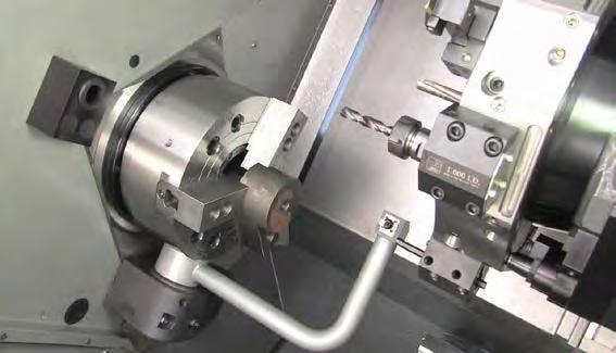
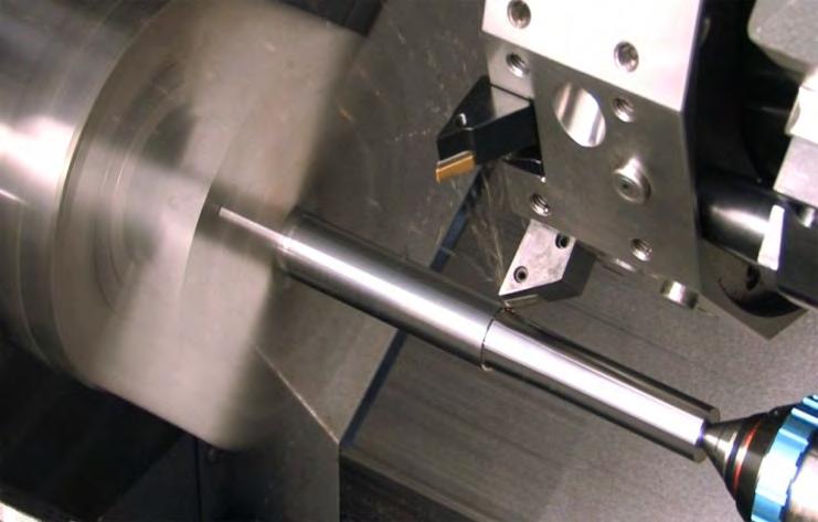
49 O00004 (BALLJOINT SIDE 1) N1 (STOCK STICKOUT 4.0 FROM JAWS) T101 (80 DEG OD TOOL.0312R) G50 S1500 (Clamp spindle speed at 1500 rev/min) G97 S682 M03 (Turn on spindle speed so at 2.1d. S375ft/min) G54 G00 X2.1 Z0.1 M08 (Rapid to position in front of part) G96 S375 (Turn on constant surface speed to 375ft/min) G01 Z0 F0.012 (Feed to face off position) G01 X-0.1 F0.007 (Face off front of part) G54 G00 X2.1 Z0.1 M08 (Rapid to G71 Start Position) G71 P11 Q21 U0.01 W F0.012 (Leave.010 on OD and.005 on face for finish) N11 G00 G42 XO ZO.1 G01 ZO F0.006 G01 X0.98 G01 X1.04 Z-0.03 (Turn.03 chamfer) G01 Z-1. G01 X1.254 G01 X1.314 Z-1.03 (Turn.03 chamfer on diam.) Z-1.4 N21 G00 G40 X2.1 (Turn off tool nose compensation to 2.1 diam.) G70 P11 Q21 (Cut Finish Pass) G97 S400 M09 G53 XO G53 Z-30. M05 MO1 Stock is 2.06 in diameter. (PART OFF WITH PECK) T202 (.125 CUT OFF) G54 G50 S400 G96 S200 M03 G54 G00 X2.1 Z0.1 (Rapid to start position) G00 Z (Rapid to cut off point in Z) G75 X0.1 Z I0.05 F0.003 (Cut off Part) G00 X2.1 Z0.05 G53 X0 (Take home in Z) G53 Z-30. (Rapid to safe in Z-30.) M30 Use CNMG 432 in 80 degree holder to face. rough and finish 1.04 and diameters. Run at surface feed 375ft/min. F.O1 in/rev rough F.007 for finish pass. Turn back to 1.4 inch from face. Cut off with.125 tool leaving OAL Cut off at S300 ft/min and feed of.003 In/rev. 1/32 radius tool
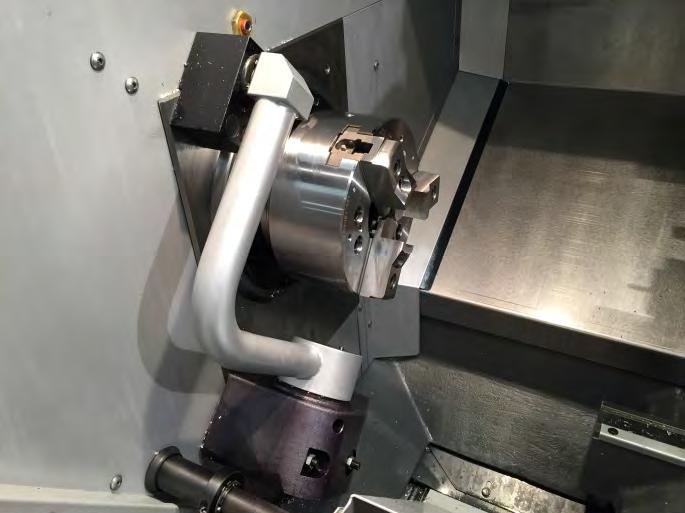
50 O00175 (BALLJOINT Side 1) N1 (35 DEG TURN) T101 (OD TOOL.0312R) N2 G50 S2500 (CLAMP SPINDLE SPEED AT 2500) N3 G97 S636 M03 N4 G54 G00 X2.25 Z0.1 M08 (START POSITION FOR G71) N5 G96 S375 N6 G71 / P1O Q20 UO.O1 W F0.012 N10 G00 G42 X Z0.l N11 G0l ZO F0.006 N12 X0 N13 G03 X0.871 Z-1.9 R1. N14 G02 X0.73 Z R0.125 N15 G01 Z N16 G01 X1.285 N18 G01 X1.385 Z N20 G00 G40 X2.25 N21 G97 S400 M09 N22 G28 M01 N2 T202 (60 DEG FIN) N23 G50 S2500 N24 G97 S1200 M03 N25 G00 X2.25 Z0.1 N26 G96 S650 N27 G70 P1O Q20 N28 G97 S400 M09 N29 G28 M30 The first side and have already been turned. Rough turn.05 depth of cut, leave.005 one face.01 on diameter for G70.
, Z-axis value I Distance and direction from first cut to last cut amount, X-axis radius value K Distance and direction from first cut to last cut amount, Z-axis value D Number of")
51 P Starting block number of part path to machine Q Ending block number of part path to machine U* Finish stock remaining with direction (+or -), X-axis diameter value W* Finish stock remaining with direction (+or -), Z-axis value I Distance and direction from first cut to last cut amount, X-axis radius value K Distance and direction from first cut to last cut amount, Z-axis value D Number of roughing passes, positive number F Roughing passes feed rate throughout this cycle S** Spindle speed to use in this cycle T** Tool and offset to use in this cycle * Indicates optional ** Rarely defined in a G73 line
 N106 G96 S370 N107 G73 P108 Q121 U.01 W.005 I0.3 K0.15 D4 F.012 (G73 Stock Removal) N108 G42 G00 X0.325 (P) (Start of geometry P number in G73 line. G42 C.")
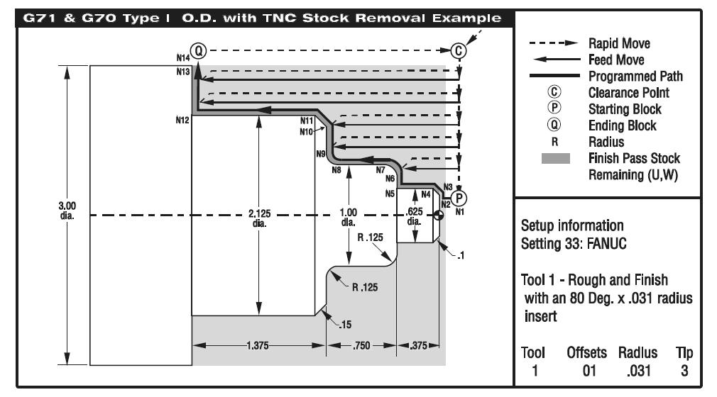
52 O00101 (G73 O.D. ROUGHING) N101 G53 G00 X-3. Z-4. T0 (Rapid to tool change location) N102 T101 (Tool 1 Offset 1) N103 G50 S3000 N104 G97 S450 M03 N105 G54 G00 X3.1 Z.1 M08 (Rapid to Start Point) N106 G96 S370 N107 G73 P108 Q121 U.01 W.005 I0.3 K0.15 D4 F.012 (G73 Stock Removal) N108 G42 G00 X0.325 (P) (Start of geometry P number in G73 line. G42 C.C. right) N109 G01 Z0. F0.01 N110 X0.425 N111 X.625 Z-0.1 F0.005 N112 Z N113 X0.75 N114 G03 X1. Z-0.5 R.125 N115 G01 Z-1. F0.003 N116 G02 X1.25 Z R.125 N117 G01 X1.825 N118 X2.125 Z N119 Z-2.5 F0.008 N120 X3. N121 G40 G00 X3.1 (Q) (End of geometry Q number in G71 line. G40 cancels C.C.) N122 G70 P108 Q121 (G70 Finishing cycle N108 thru N121) N123 G97 S450 M09 N124 G53 G00 X-3. Z-4. T0 (Rapid to tool change location) N125 M30 (End of Program)


53 X X axis absolute pecking depth, diameter value. Z* Z axis absolute location to the furthest peck. U* X axis incremental pecking depth, diameter value. W* Z axis incremental distance and direction (+or -) to the furthest peck. I * X axis pecking depth increment, radius value. K* Z axis shift increment between pecking cycles. D* Tool shift amount when returning to clearance plane F Feed rate * Optional
54 O00107 (G74 High Speed Peck Drilling example) (Drill a.500 Diameter to a.525 Depth) N1 G28 N2 T404 (1/2 DIA. DRILL) N3 G97 S2445 M03 N4 G54 G00 X0. Z0.1 M08 (Rapid to X0 and Z start point) N5 G74 Z-.525 K0.1 F0.006 (Drills to Z-.525 depth, pecking every.1 to pull) N6 G00 Z1.0 M09 (back after each peck the amount in Setting 22.) N7 G28 N8 M30 SETTING 22 (CAN CYCLE DELTA Z) - As the groove tool pecks deeper into the part, with each peck value of I, it pulls back a constant specified distance above the bottom of the groove created by the previous peck to break the chip. That specified distance it pulls back is defined in Setting 22.
 to the furthest peck. I * X-axis pecking depth increment, radius value. K* Z-axis shift increment between pecking cycles.")
55 X X-axis absolute pecking depth, diameter value. Z* Z-axis absolute location to the furthest peck. U* X-axis incremental pecking depth, diameter value. W* Z-axis incremental distance and direction (+or -) to the furthest peck. I * X-axis pecking depth increment, radius value. K* Z-axis shift increment between pecking cycles. D* Tool shift amount when returning to clearance plane.(caution see NOTE) F Feed rate * Indicates optional
56 O00109 (G75 O.D./I.D. SINGLE PASS GROOVE CYCLE) (Machine a.25 wide O.D. Groove with.25 Groove Tool) N1 G28 N2 T505 (.25 WIDE O.D. GROOVE TOOL) N3 G97 S960 M03 N4 G54 G00 X2.1 Z0.1 M08 (Rapid to clearance point) N5 Z-0.75 (Rapid to a start point of groove) N6 G75 X1.75 I0.05 F0.005 (G75 Single pass O.D. grooving cycle) N7 M09 N8 G28 N9 M30 SETTING 22 (CAN CYCLE DELTA Z) - As the groove tool pecks deeper into the part, with each peck value of I, it pulls back a constant specified distance above the bottom of the groove created by the previous peck to break the chip. That specified distance it pulls back is defined in Setting 22.
57 (Machine a 1. wide O.D. Groove with.25 Groove Tool) O00110 (G75 O.D./I.D. MULTIPLE PASS GROOVING CYCLE) N1 G28 N2 T505 (.25 WIDE O.D. GROOVE TOOL) N3 G97 S960 M03 N4 G54 G00 X2.1 Z0.1 M08 (Rapid to front of part) N5 Z-0.75 (Rapid to start point of groove) N6 G75 X1.75 Z-1.5 I0.05 K0.2 F0.005 (G75 Multiple pass O.D. grooving cycle) N7 M09 N8 G28 N9 M30 SETTING 22 (CAN CYCLE DELTA Z) - As the groove tool pecks deeper into the part, with each peck value of I, it pulls back a constant specified distance above the bottom of the groove created by the previous peck to break the chip. That specified distance it pulls back is defined in Setting 22.

58 X* X-axis absolute thread finish point, diameter value. Z* Z-axis absolute distance, thread end point location. U* X-axis incremental total distance to finish point, diameter. W* Z-axis incremental thread length finish point. K Thread height, radius value I* Thread taper amount, radius value. D First pass cutting depth. P Thread Cutting Method P1-P4 (added in software ver. 6.05) A* Tool nose angle, no decimal with A command. (0 to 120 degrees, If not used then 0 degrees is assumed) F Feed rate (Threading feed rate, is the thread distance per revolution) * Indicates optional

59 Image courtesy of Kennametal

60 Image courtesy of Kennametal
61 1. The G76 canned cycle can be used for threading both straight or tapered (pipe) threads. With G76 a programmer can easily command multiple cutting passes along the length of a thread. 2. The height of the thread is specified in K. The height of the thread is defined as the distance from the crest of the thread to the root. The calculated depth of the thread will be K less the finish allowance. Setting 86 (THREAD FINISH ALLOWANCE) is this stock allowance for a finish pass allowance, if needed. 3. The depth of the first cut of the thread is specified in D. This also determines the number of passes over the thread based on the value of K and the cutting method used. D = k/ N where N=passes. 1. The depth of the last cut on the thread can be controlled with Setting 99 (THREAD MINIMUM CUT). 2. The last cut will never be less than this value. The default value is.001 inches/.01 mm. ; e.g. ½-13, F=1/13= The feed rate F : F = 1 TTT


62 The thread taper distance amount is specified with the I command. It is measured from the target end position in X and Z axis down to the point in X axis where this cycle begins and is a radius amount. A conventional O.D. taper thread will have a negative I value and a conventional I.D. taper thread will have a positive I value.
 N50 Z0.2 M23 (Z start point, chamfer at end of thread ON) N60 G76 X0.674 Z-1.25 K0.0383 D0")
63 O00113 (G76 Multiple threading cycle to machine a 3/4-16 O.D. thread) N10 G28 N20 T606 (O.D. THREADING TOOL) N30 G97 S720 M03 N40 G54 G00 X0.85 Z1. M08 (Rapid to start point above diameter of the part) N50 Z0.2 M23 (Z start point, chamfer at end of thread ON) N60 G76 X0.674 Z-1.25 K D F (G76 Multiple pass O.D. thread) N70 M09 N80 G28 N90 M30 Angle out of threads at end: M23 Chamfer On (DEFAULT) M24 Chamber Off
64 M23 Chamfer (angle out of thread) at End of Thread is ON (DEFUALT) An angle out of thread move can improve the appearance and functionality of a thread. This M23 commands the control to exit the thread with angle out move on a thread executed by a G76 or G92. This M code is modal and is also the default. It remains in effect until changed by M24. Refer to Settings 95 and 96 to control the move distance and angle. M23 will again be active, with an M30, RESET, or a POWER ON condition. SETTING 95 (THREAD CHAMFER SIZE) - The distance of angling out of the thread. The distance is designated thread pitch, so that if 1.0 is in Setting 95 and the threading feed rate is.05, then the angle out distance will be The default in Setting 95 is SETTING 96 (THREAD CHAMFER ANGLE) - Angle out of thread chamfer. The default angle of 45 degrees is in Setting 96. M24 Chamfer (angle out of thread) at End of Thread is OFF An M24 commands the control to perform no angle out departure move at the end of a G76 or G92 threading cycle. This M code is modal. M24 is cancelled with an M23 (Chamfer at End of Thread ON), RESET, M30 or a POWER ON condition.
65 O00119 (G81 Drilling; ½ drill) N1 G28 N2 T101 (1/2 DIA. DRILL) (Tool 1 Offset 1) N3 G97 S1450 M03 N4 G54 G00 X0. Z1. M08 (Rapid to Initial Start Point) N5 G81 Z R0.1 F0.005 (G81 Drilling Cycle) N6 G80 G00 Z1. M09 (G80 cancels G81) N7 G28 N8 M30 X* Absolute X-axis rapid location. Z* Absolute Z-depth (feeding to Z-depth starting from R- plane). W* Incremental Z-depth (feeding to Z-depth starting from R-plane). R Rapid to R-plane (where you rapid, to start feeding). F Feed rate. * Indicates optional
66 O00120 (G82 Drilling with a Dwell; ½ FB drill) N1 G28 N2 T202 (1/2 DIA. FLAT BOTTOM DRILL) (Tool 2 Offset 2) N3 G97 S1450 M03 N4 G54 G00 X0. Z1. M08 (Rapid to Initial Start Point) N5 G82 Z P0.5 R0.1 F0.005 (G82 Drill with a Dwell at Z Depth Cycle) N6 G80 G00 Z1. M09 (G80 cancels G82) N7 G28 N8 M30 X* Absolute X-axis rapid location. Z* Absolute Z-depth (feeding to Z-depth starting from R-plane). W* Incremental Z-depth (feeding to Z-depth starting from R-plane). P Dwell time at Z-depth R Rapid to R-plane (where you rapid, to start feeding). F Feed rate. * Indicates optional
 N6 G80 G00 Z1. M09 N7 G28 N8 M30 X* Absolute X-axis rapid location. Z* Absolute Z-depth (feeding to Z- depth starting from R-plane).")
67 O00121 (G83 Peck Drilling; ½ drill) N1 G28 N2 T303 (1/2 DIA. DRILL) (Tool 3 Offset 3) N3 G97 S1820 M03 N4 G54 G00 X0. Z1. M08 (Rapid to Initial Start Point) N5 G83 Z-1.5 Q0.2 R0.1 F0.005 (G83 Peck Drilling Cycle with Q) N6 G80 G00 Z1. M09 N7 G28 N8 M30 X* Absolute X-axis rapid location. Z* Absolute Z-depth (feeding to Z- depth starting from R-plane). W* Incremental Z-depth (feeding to Z-depth starting from R-plane). Q* Pecking depth amount, always incremental (if I, J and K are not used). I* Size of first peck depth (if Q is not used). J* Amount reducing each peck after first peck depth (if Q is not used). K* Minimum peck depth (if Q is not used). P Dwell time at Z-depth. R Rapid to R-plane (where you rapid, to start feeding). F Feed rate. * Indicates optional
 N6 G80 G00 Z1. M09 N7 G28 N8 M30 X* Absolute X-axis rapid location. Z* Absolute Z-depth (feeding to Z-depth. starting from R-plane).")
68 O00123 (G84 Tapping) N1 G28 N2 T404 (3/8-16 TAP) (Tool 4 Offset 4) N3 G97 S650 M05 (G84 will turn on the spindle for you) N4 G54 G00 X0. Z1. M08 (Rapid to Initial Start Point) N5 G84 Z-0.75 R0.2 F (G84 Tapping Cycle) N6 G80 G00 Z1. M09 N7 G28 N8 M30 X* Absolute X-axis rapid location. Z* Absolute Z-depth (feeding to Z-depth. starting from R-plane). W* Incremental Z-depth (feeding to Z-depth starting from R-plane). R Rapid to R-plane (where you rapid, to start feeding). F Feed rate. * Optional Use G184 for left handed taps.
69 G50 S200 (Clamp spindle speed 200 rpm) G28 (Rapid to machine zero) MO1 (Optional program stop) T404 (OD THREAD tool) G97 S655 M3 (Start spindle, D=1.748, SFM=300, RPM=655) G54 G00 X1.848 Z0.2 M08 (Rapid to start position, coolant on) G76 X1.673 Z-1.1 K.039 D.0125 A58 F.0625 (Thread cycle, X=minor diam., Z=into groove, K=thread depth from table, D=first pass from table, A=60-2 degrees to cut on both sides, F=feed=1/TPI=1/16, using Kennametal table ) M09 (Coolant off) G28 MO1 T1111 (5/16 DRILL) G97 S976 M3 (Start spindle, D=5/16=.313, SFM=80, RPM=976) G54 G00 X0 Z0.2 M08 (Rapid to start position, coolant on) G83 X0 Z-1.3 R.1 Q F.006 (Drill peck cycle) G80 (Cancel canned cycle) G00 Z0.2 (Return to start) G28 M09 M01 T1010 (3/8-16 TAP) G97 S200 M05 (RPM given and stop spindle) G54 G00 X0 Z0.5 M08 (Rapid to start position, coolant on) G84 X0 Z-1 R0.5 F (Tap cycle, R plane 500 in front, feed=1/tpi=1/16) G80 G28 M30 (End) T0404 Thread G761-3/4-16 UN 2A 1.0" back from face SFM=300 ft/min. Major diameter 1.748, Minor diameter T1111 5/16 Drill G83 1.3" deep SFM=80 ft/min F.006"/rev peck diameter of drill T1010 Tap 3/8-16 x 1.0" deep at 200 rpm
70 G90 O.D./I.D. Turning It can be used for simple turning. Since it is modal, you can do multiple passes for turning by just specifying a new X location for successive passes. G92 Thread Cutting It can be used for simple threading. Since it is modal, you can do multiple passes for threading by just specifying a new X location for successive passes. Straight threads can be made by just specifying X, Z and F. By adding I a pipe or taper thread can be cut. The amount of taper is defined with the I value added to the X value target point. At the end of the thread, an automatic chamfer is executed before reaching the target default for this chamfer is one thread at 45 degrees. G94 End Face Cutting You can do multiple passes for facing by just specifying a new Z location for successive passes. Straight end facing cuts can be made by just specifying X, Z and F. By adding K a conical face can be cut. The coning amount is defined with the K value that is added to the Z value target point.
 N11 G28 N12 T101 (O.D. TURNING TOOL) N13 G50 S3000 N14 G97 S480 M03 N15 G54 G00 X1.85 Z1.")
71 X* Absolute X-axis target location Z* Absolute Z-axis target location U* Incremental X-axis target distance, diameter W* Incremental Z-axis target distance I * Distance and direction of X axis ta per, radius value F Feed rate * Indicates optional O00131 (G90 Modal Turning with TNC) N11 G28 N12 T101 (O.D. TURNING TOOL) N13 G50 S3000 N14 G97 S480 M03 N15 G54 G00 X1.85 Z1. M08 (Rapid to Start Point) N16 G96 S390 N17 Z0.1 N18 G90 G42 X1.65 Z I F0.006 (Rough 30 Deg. angle to X2.3476) N19 X1.55 (Additional Pass) (Dia. using G90 and TNC) N20 X1.45 (Additional Pass) N21 X1.35 (Additional Pass) N22 X1.25 (Additional Pass) N23 G00 G40 X3.1 Z1. M09 (TNC Departure) N24 M05 N25 G28 N26 M30
 N10 (1.0-12UN Thread) N11 G28 N12 T404 (O.D. THREADING TOOL) N13 G97 S825 M03 N14 G54 G00 X1.1 Z1.")
72 X* Absolute X-axis target location Z* Absolute Z-axis target location U* Incremental X-axis target distance, diameter W* Incremental Z-axis target distance I* Distance and direction of X axis taper, radius value F Feed rate * Indicates optional O00133 (G92 Modal Threading) N10 (1.0-12UN Thread) N11 G28 N12 T404 (O.D. THREADING TOOL) N13 G97 S825 M03 N14 G54 G00 X1.1 Z1. M08 (Rapid to Start Point) N15 Z0.25 N16 G92 X.98 Z-1.05 F M23 (First Pass of a G92 O.D. Thread Cycle) N17 X.96 (Additional Pass) N18 X.94 (Additional Pass) N19 X.935 (Additional Pass) N20 X.93 (Additional Pass) N21 X.925 (Additional Pass) N22 X.9225 (Additional Pass) N23 X.92 (Additional Pass) N24 X.9175 (Additional Pass) N25 X.9155 (Additional Pass) N26 X.915 (Additional Pass) N27 X.9148 (Additional Pass) N28 G00 X1.1 Z1. M09 N29 M05 N30 G28 N31 M30N31 M30
 N11 G28 N12 T101 (O.D. FACING TOOL) N13 G50 S3000 N14 G97 S480 M03 N15 G54 G00 X3.1 Z1.")
73 X* Absolute X-axis target location Z* Absolute Z-axis target location U* Incremental X-axis target distance, diameter W* Incremental Z-axis target distance K* Distance and direction of Z axis coning F Feed rate * Indicates optional O00135 (G94 Modal End Facing with TNC example) N11 G28 N12 T101 (O.D. FACING TOOL) N13 G50 S3000 N14 G97 S480 M03 N15 G54 G00 X3.1 Z1. M08 (Rapid above part) N16 G96 S390 N17 Z.1 (rapid to start point) N18 G94 G41 X1.0 Z-0.3 K F0.01 (Rough 30 Deg. angle to X1. and Z-0.7 using G94 and TNC) N19 Z-0.4 (Additional Pass) Z-0.7 using G94 and TNC) N20 Z-0.5 (Additional Pass) N21 Z-0.6 (Additional Pass) N22 Z-0.69 (Additional Pass) N23 Z-0.7 (Additional Pass) N24 G40 G00 X3.1 Z1. M09 (Cancel TNC) N25 M05 N26 G28 N27 M30
74 Axis X & Z, Absolute & Incremental Positioning Programming G Commands G00, G01, G02, G03, G04, G28, G50, G51, G96, G97, G98, G99 M Machine Controls Letter Address Codes Tool Nose Compensation G40, G41, G42 Canned Cycles Turning and Grooving G70, G71, G73, G74, G75, G76 Canned Cycles for Drilling and Tapping G80, G81, G82, G84
75 Haas CNC Lathe Operator 2014 Haas CNC Lathe Programming 2015 Haas Lathe Operator s Manual 2016 Haas Programming Workbook 2015 Haas EBay Tutorials
Prof. Steven S. Saliterman Introductory Medical Device Prototyping
 Introductory Medical Device Prototyping Department of Biomedical Engineering, University of Minnesota http://saliterman.umn.edu/ You must complete safety instruction before using tools and equipment in
HAAS AUTOMATION, INC.
 PROGRAMMING WORKBOOK HAAS AUTOMATION, INC. 2800 Sturgis Rd. Oxnard, CA 93030 JANUARY 2005 . JANUARY 2005 PROGRAMMING HAAS AUTOMATION INC. 2800 Sturgis Road Oxnard, California 93030 Phone: 805-278-1800
Lathe Series Training Manual. Haas CNC Lathe Programming
 Haas Factory Outlet A Division of Productivity Inc Lathe Series Training Manual Haas CNC Lathe Programming Revised 050914; Rev3-1/29/15; Rev4-31017 This Manual is the Property of Productivity Inc The document
SHOP NOTES. GPocket Guide and Reference Charts. for CNC Machinists. Made in the U.S.A.
 SHOP NOTES GPocket Guide and Reference Charts for CNC Machinists Made in the U.S.A. WHAT S INSIDE THIS BOOKLET? Decimal Equivalent Chart / Millimeter to Inch Chart Haas Mill G-Codes / Haas Mill M-Codes
Table of Contents. Preface 9 Prerequisites 9. Key Concept 1: Know Your Machine From A Programmer s Viewpoint 13. Table of Contents
 Preface 9 Prerequisites 9 Basic machining practice experience 9 Controls covered 10 Limitations 10 Programming method 10 The need for hands -on practice 10 Instruction method 11 Scope 11 Key Concepts approach
PROGRAMMING January 2005
 PROGRAMMING January 2005 CANNED CYCLES FOR DRILLING TAPPING AND BORING A canned cycle is used to simplify programming of a part. Canned cycles are defined for the most common Z-axis repetitive operation
Mach4 CNC Controller Lathe Programming Guide Version 1.0
 Mach4 CNC Controller Lathe Programming Guide Version 1.0 1 Copyright 2014 Newfangled Solutions, Artsoft USA, All Rights Reserved The following are registered trademarks of Microsoft Corporation: Microsoft,
HAAS AUTOMATION, INC.
 PROGRAMMING WORKBOOK HAAS AUTOMATION, INC. 2800 Sturgis Rd. Oxnard, CA 93030 January 2005 JANUARY 2005 PROGRAMMING HAAS AUTOMATION INC. 2800 Sturgis Road Oxnard, California 93030 Phone: 805-278-1800 www.haascnc.com
Preview Sample. Date: September 1, 2010 Author: Matthew Manton and Duane Weidinger ISBN:
 Computer Numerical Control Workbook Generic Lathe Published by CamInstructor Incorporated 330 Chandos Crt. Kitchener, Ontario N2A 3C2 www.caminstructor.com Date: September 1, 2010 Author: Matthew Manton
G02 CW / G03 CCW Circular Interpolation Motion (Group 01) - Mill
 - Mill") Haas Technical Documentation G02 CW / G03 CCW Circular Interpolation Motion (Group 01) - Mill Scan code to get the latest version of this document Translation Available G02 CW / G03 CCW Circular Interpolation
Haas Technical Documentation G02 CW / G03 CCW Circular Interpolation Motion (Group 01) - Mill Scan code to get the latest version of this document Translation Available G02 CW / G03 CCW Circular Interpolation
COMPUTER INTEGRATED MANUFACTURING LABORATORY (14AME31)
") COMPUTER INTEGRATED MANUFACTURING LABORATORY (14AME31) (For III B.Tech - II SEM- Mechanical Engineering) DEPARTMENT OF MECHANICAL ENGINEERING SRI VENKATESWARA COLLEGE OF ENGINEERING & TECHNOLOGY R.V.S
COMPUTER INTEGRATED MANUFACTURING LABORATORY (14AME31) (For III B.Tech - II SEM- Mechanical Engineering) DEPARTMENT OF MECHANICAL ENGINEERING SRI VENKATESWARA COLLEGE OF ENGINEERING & TECHNOLOGY R.V.S
Figure 1: NC Lathe menu
 Click To See: How to Use Online Documents SURFCAM Online Documents 685)&$0Ã5HIHUHQFHÃ0DQXDO 5 /$7+( 5.1 INTRODUCTION The lathe mode is used to perform operations on 2D geometry, turned on two axis lathes.
CAD/CAM/CAE Computer Aided Design/Computer Aided Manufacturing/Computer Aided Manufacturing. Part-10 CNC Milling Programming
 CAD/CAM/CAE Computer Aided Design/Computer Aided Manufacturing/Computer Aided Manufacturing Part-10 CNC Milling Programming To maximize the power of modern CNC milling machines, a programmer has to master
Motion Manipulation Techniques
 Motion Manipulation Techniques You ve already been exposed to some advanced techniques with basic motion types (lesson six) and you seen several special motion types (lesson seven) In this lesson, we ll
Prof. Steven S. Saliterman Introductory Medical Device Prototyping
 Introductory Medical Device Prototyping Department of Biomedical Engineering, University of Minnesota http://saliterman.umn.edu/ You must complete safety instruction before using tools and equipment in
Table of Contents. Table of Contents. Preface 11 Prerequisites... 12
 Table of Contents Preface 11 Prerequisites... 12 Basic machining practice experience... 12 Controls covered... 12 Limitations... 13 The need for hands -on practice... 13 Instruction method... 13 Scope...
527F CNC Control. User Manual Calmotion LLC, All rights reserved
 527F CNC Control User Manual 2006-2016 Calmotion LLC, All rights reserved Calmotion LLC 21720 Marilla St. Chatsworth, CA 91311 Phone: (818) 357-5826 www.calmotion.com NC Word Summary NC Word Summary A
NZX NLX
 NZX2500 4000 6000 NLX1500 2000 2500 Table of contents: 1. Introduction...1 2. Required add-ins...1 2.1. How to load an add-in ESPRIT...1 2.2. AutoSubStock (optional) (for NLX configuration only)...3 2.3.
Lathe Series Training Manual. Live Tool for Haas Lathe (including DS)
") Haas Factory Outlet A Division of Productivity Inc Lathe Series Training Manual Live Tool for Haas Lathe (including DS) Created 020112-Rev 121012, Rev2-091014 This Manual is the Property of Productivity
Haas Factory Outlet A Division of Productivity Inc Lathe Series Training Manual Live Tool for Haas Lathe (including DS) Created 020112-Rev 121012, Rev2-091014 This Manual is the Property of Productivity
CNC Machinery. Module 4: CNC Programming "Turning" IAT Curriculum Unit PREPARED BY. August 2009
 CNC Machinery Module 4: CNC Programming "Turning" PREPARED BY IAT Curriculum Unit August 2009 Institute of Applied Technology, 2009 2 Module 4: CNC Programming "Turning" Module 4: CNC Programming "Turning"
NUMERICAL CONTROL.
 NUMERICAL CONTROL http://www.toolingu.com/definition-300200-12690-tool-offset.html NC &CNC Numeric Control (NC) and Computer Numeric Control (CNC) are means by which machine centers are used to produce
OmniTurn Training. Jeff Richlin OmniTurn Training Manual Richlin Machinery - (631)
") OmniTurn Training Jeff Richlin 631 694 9400 jrichlin@gmail.com OmniTurn Training Manual Richlin Machinery - (631) 694 9400 1 OmniTurn Training Manual Richlin Machinery - (631) 694 9400 2 Codes Honored
OmniTurn Training Jeff Richlin 631 694 9400 jrichlin@gmail.com OmniTurn Training Manual Richlin Machinery - (631) 694 9400 1 OmniTurn Training Manual Richlin Machinery - (631) 694 9400 2 Codes Honored
Mill Series Training Manual. Haas CNC Mill Programming
 Haas Factory Outlet A Division of Productivity Inc Mill Series Training Manual Haas CNC Mill Programming Revised 021913 (Printed 02-2013) This Manual is the Property of Productivity Inc The document may
OmniTurn Start-up sample part
 OmniTurn Start-up sample part OmniTurn Sample Part Welcome to the OmniTum. This document is a tutorial used to run a first program with the OmniTurn. It is suggested before you try to work with this tutorial
CNC LATHE TURNING CENTER PL-20A
 CNC LATHE TURNING CENTER PL-20A CNC LATHE TURNING CENTER For High Precision, High Speed and High Productivity MAIN FEATURE Introducing the latest and strongest CNC Lathe PL20A that has satisfied the requirements
Projects. 5 For each component, produce a drawing showing the intersection BO.O. C'BORE 18 DIA x 5 DEEP FROM SECTION ON A - A
 Projects ~ Figure Pl Project 1 If you have worked systematically through the assignments in this workbook, you should now be able to tackle the following milling and turning projects. It is suggested that
CNC Programming Guide MILLING
 CNC Programming Guide MILLING Foreword The purpose of this guide is to help faculty teach CNC programming without tears. Most books currently available on CNC programming are not only inadequate, but also
Getting Started. Terminology. CNC 1 Training
 CNC 1 Training Getting Started What You Need for This Training Program This manual 6 x 4 x 3 HDPE 8 3/8, two flute, bottom cutting end mill, 1 Length of Cut (LOC). #3 Center Drill 1/4 drill bit and drill
CNC PROGRAMMING WORKBOOK. Sample not for. Distribution MILL & LATHE. By Matthew Manton and Duane Weidinger
 CNC PROGRAMMING WORKBOOK MILL & LATHE By Matthew Manton and Duane Weidinger CNC Programming Workbook Mill & Lathe Published by: CamInstructor Incorporated 330 Chandos Crt. Kitchener, Ontario N2A 3C2 www.caminstructor.com
Table 5.1: Drilling canned cycles. Action at the bottom of the hole. Cancels drilling canned cycle Intermittent or continuous feed.
 5.18 CANNED CYCLES FOR DRILLING On a lathe, equipped with live tooling (which allows a tool, obviously a drilling or a similar tool, to rotate at the specified RPM, as in a milling machine) and an additional
NC Programming for PUMA Turning Centers Equipped with Live Tools, Sub Spindle, Y- Axis
 NC Programming for PUMA Turning Centers Equipped with Live Tools, Sub Spindle, Y- Axis For PUMA Turning Centers 200M, 200MS, 230M, 230MS, 240M, 240MS, 300M, 300MS 1500Y/SY, 2000Y/SY, 2500Y/SY 1 TABLE OF
CNC Applications. Programming Machining Centers
 CNC Applications Programming Machining Centers Planning and Programming Just as with the turning center, you must follow a series of steps to create a successful program: 1. Examine the part drawing thoroughly
Lathe Code. Lathe Specific Additions. 1 de 15 27/01/ :20. Contents. 1. Introduction DesktopCNC?
 1 de 15 27/01/2010 14:20 Lathe Code EmcKnowledgeBase RecentChanges PageIndex Preferences LinuxCNC.org Search: Lathe Specific Additions Contents 1. Introduction 2. Lathe G codes 2.1. DesktopCNC 2.2. Haas
Manual Guide i. Lathe Training Workbook. For. Lathe Turning & Milling
 Manual Guide i Lathe Training Workbook For Lathe Turning & Milling A-816A Hardinge Inc., 2008 Part No. A A-0009500-0816 Litho in USA June 2008 2 Section Pages Section One: Basic Machine Operations Sequence
VMC Series II Vertical Machining Centers PROGRAMMER S MANUAL. Equipped with the Hardinge / Fanuc System II, Fanuc 0i-M, or Fanuc 18-MC Control
 PROGRAMMER S MANUAL VMC Series II Vertical Machining Centers Equipped with the Hardinge / Fanuc System II, Fanuc 0i-M, or Fanuc 18-MC Control Revised: July 26, 2004 Manual No. M-377B Litho in U.S.A. Part
Cobra Series CNC Lathes
 PROGRAMMER S MANUAL TP1480B TP3264 TP2580 Cobra Series CNC Lathes Equipped with the GE Fanuc 21T Control Manual No. M-312C Litho in U.S.A. Part No. M C-0009500-0312 October, 1998 - NOTICE - Damage resulting
WINMAX LATHE NC PROGRAMMING
 WINMAX LATHE NC PROGRAMMING Dual-screen and Max Consoles for Hurco Turning Centers March 2012 704-0115-306 Revision A The information in this document is subject to change without notice and does not represent
FNL-220Y / 220SY / 200LS Series CNC Turning-Milling Machines Linear Way
 RICH WELL 206.0 Dimensions R450 E FNL-220Y / 220SY / 200LS Series CNC Turning-Milling Machines Linear Way 20 C D Chip conveyor 092 H G B 46 575 A F Unit:mm A B C D E F G H FNL220LSY/FNL220LY 952 2946 2700
PROGRAMMER S MANUAL CNC Lathes Equipped with the GE Fanuc 18T Control
 PROGRAMMER S MANUAL TP1421 CNC Lathes Equipped with the GE Fanuc 18T Control Revised: September 28, 1999 Manual No. M-320A Litho in U.S.A. Part No. M A-0009500-0320 April, 1997 - NOTICE - Damage resulting
FANUC SERIES 21i/18i/16i TA. Concise guide Edition 03.01
 FANUC SERIES 21i/18i/16i TA Concise guide Edition 03.01 0.1 GENERAL INDEX- CONCISE GUIDE FOR PROGRAMMER PAGE PAR. CONTENTS 7 1.0 FOREWORD 8 2.0 NC MAIN FUNCTIONS AND ADDRESSES 8 2.1 O Program and sub-program
1640DCL Digital Control Lathe
 1640DCL Digital Control Lathe MACHINE SPECIFICATIONS Multiple Function CNC Lathe 1. Manual Hand wheel Operation 2. CNC G-Code Operation 16.1 swing over bed, 8.6 swing over cross-slide 2.05 diameter hole
WINMAX LATHE NC PROGRAMMING
 WINMAX LATHE NC PROGRAMMING Dual-screen and Max Consoles for Hurco Turning Centers April 2013 704-0115-309 Revision A The information in this document is subject to change without notice and does not represent
Turning and Lathe Basics
 Training Objectives After watching the video and reviewing this printed material, the viewer will gain knowledge and understanding of lathe principles and be able to identify the basic tools and techniques
Chapter 22 MACHINING OPERATIONS AND MACHINE TOOLS
 Chapter 22 MACHINING OPERATIONS AND MACHINE TOOLS Turning and Related Operations Drilling and Related Operations Milling Machining Centers and Turning Centers Other Machining Operations High Speed Machining
BHARATHIDASAN ENGINEERING COLLEGE NATTRAMPALLI DEPARTMENT OF MECHANICAL ENGINEERING LABORATORY MANUAL ME6411-MANUFACTURING TECHNOLOGY LAB- II
 BHARATHIDASAN ENGINEERING COLLEGE NATTRAMPALLI 635 854 DEPARTMENT OF MECHANICAL ENGINEERING LABORATORY MANUAL ME6411-MANUFACTURING TECHNOLOGY LAB- II YEAR / SEMESTER : II / IV DEPARTMENT : Mechanical REGULATION
Techniques With Motion Types
 Techniques With Motion Types The vast majority of CNC programs require but three motion types: rapid, straight line, and circular interpolation. And these motion types are well discussed in basic courses.
Trade of Toolmaking. Module 6: Introduction to CNC Unit 2: Part Programming Phase 2. Published by. Trade of Toolmaking Phase 2 Module 6 Unit 2
 Trade of Toolmaking Module 6: Introduction to CNC Unit 2: Part Programming Phase 2 Published by SOLAS 2014 Unit 2 1 Table of Contents Document Release History... 3 Unit Objective... 4 Introduction... 4
MACHINIST S REFERENCE GUIDE
 MACHINIST S REFERENCE GUIDE Hurco Companies, Inc. One Technology Way / P.O. Box 68180 Indianapolis, IN 46268-0180 800.634.2416 Info@hurco.com HURCO.com Hurco Applications Hotline 317.614.1549 applications@hurco.com
User s Manual Cycle Programming TNC 320. NC Software
 User s Manual Cycle Programming TNC 320 NC Software 340 551-04 340 554-04 English (en) 9/2009 About this Manual The symbols used in this manual are described below. This symbol indicates that important
CNC TURNING CENTER 3. (06. 07) Head Office. Seoul Office. Head Office & Factory. HYUNDAI - KIA MACHINE AMERICA CORP. (New Jersey Office)
 Head Office. Seoul Office. Head Office & Factory. HYUNDAI - KIA MACHINE AMERICA CORP. (New Jersey Office)") CNC TURNING CENTER Head Office Head Office & Factory. (06. 07 Seoul Office HYUNDAI - KIA MACHINE AMERICA CORP. (New Jersey Office HYUNDAI - KIA MACHINE AMERICA CORP. (Chicago Office HYUNDAI - KIA MACHINE
CNC TURNING CENTER Head Office Head Office & Factory. (06. 07 Seoul Office HYUNDAI - KIA MACHINE AMERICA CORP. (New Jersey Office HYUNDAI - KIA MACHINE AMERICA CORP. (Chicago Office HYUNDAI - KIA MACHINE
CNC Applications. Tool Nose Radius Compensation on Turning Centers
 CNC Applications Tool Nose Radius Compensation on Turning Centers Facing and Straight Turning When facing or straight turning, the tool nose radius has no effect on the part other than leaving a radius
HAAS AUTOMATION, INC. PROGRAMMING MILL SERIES WORKBOOK ANSWERS HAAS AUTOMATION, INC STURGIS ROAD OXNARD, CA
 HAAS AUTOMATION, INC. MILL SERIES PROGRAMMING WORKBOOK HAAS AUTOMATION, INC. 2800 STURGIS ROAD OXNARD, CA 93030 www.haascnc.com 800-331-6746 ANSWERS PROGRAMMING HAAS AUTOMATION INC. 2800 Sturgis Road Oxnard,
Miyano Evolution Line
 Evolution Line CNC Turning center with 2 spindles, 2 turrets and 1 -axis slide BNJ-34/42/51 "Evolution and Innovation" is the Future What could not be done can be done. -axis movement is added to the traditional
MANUAL GUIDE i Turning Examples GE FANUC
 MANUAL GUIDE i Turning Examples GE FANUC Contents OVERVIEW OF THE MANUAL GUIDE i PROGRAMMING PROCESS 5 Structure of a MANUAL GUIDE i Program 5 Structure of an Operation 5 Fixed Form Sentences 6 DEFINING
Performance. CNC Turning & Milling Machine. Conversational CAM 3.11 Instruction Manual
 Performance CNC Turning & Milling Machine Conversational CAM 3.11 Instruction Manual Legacy Woodworking Machinery 435 W. 1000 N. Springville, UT 84663 Performance Axis CNC Machine 2 Content Warranty and
Introduction to Machining: Lathe Operation
 Introduction to Machining: Lathe Operation Lathe Operation Lathe The purpose of a lathe is to rotate a part against a tool whose position it controls. It is useful for fabricating parts and/or features
LinuxCNC Help for the Sherline Machine CNC System
 WEAR YOUR SAFETY GLASSES FORESIGHT IS BETTER THAN NO SIGHT READ INSTRUCTIONS BEFORE OPERATING LinuxCNC Help for the Sherline Machine CNC System LinuxCNC Help for Programming and Running 1. Here is a link
Touch Probe Cycles itnc 530
 Touch Probe Cycles itnc 530 NC Software 340 420-xx 340 421-xx User s Manual English (en) 4/2002 TNC Models, Software and Features This manual describes functions and features provided by the TNCs as of
Prof. Steven S. Saliterman Introductory Medical Device Prototyping
 Introductory Medical Device Prototyping Department of Biomedical Engineering, University of Minnesota http://saliterman.umn.edu/ You must complete safety instruction before using tools and equipment in
1/24/2018. Prof. Steven S. Saliterman. Right: Image courtesy of Copper Safety. Prof. Steven S. Saliterman
 Introductory Medical Device Prototyping Department of Biomedical Engineering, University of Minnesota http://saliterman.umn.edu/ You must complete safety instruction before using tools and equipment in
Lesson 2 Understanding Turning Center Speeds and Feeds
 Lesson 2 Understanding Turning Center Speeds and Feeds Speed and feed selection is one of the most important basic-machining-practice-skills a programmer must possess. Poor selection of spindle speed and
Codes Honored by the OmniTurn control (Sort by Code)
") Codes Honored by the OmniTurn control (Sort by Code) Code Usage Description Pages G00 G00 Rapid move...11,12 G01 G01Fn Feed move...12,13 G02 G02XnZnInKnFn Arc -Clockwise... 6,15,17-24 G02 G02XnZnRn Arc
Codes Honored by the OmniTurn control (Sort by Code) Code Usage Description Pages G00 G00 Rapid move...11,12 G01 G01Fn Feed move...12,13 G02 G02XnZnInKnFn Arc -Clockwise... 6,15,17-24 G02 G02XnZnRn Arc
CNC Machinery. Module 5: CNC Programming / Milling. IAT Curriculum Unit PREPARED BY. August 2009
 CNC Machinery Module 5: CNC Programming / Milling PREPARED BY IAT Curriculum Unit August 2009 Institute of Applied Technology, 2009 ATM313-CNC Module 5: CNC Programming / Milling Module Objectives: 1.
SAMSUNG Machine Tools PL35 CNC TURNING CENTER
 SAMSUNG Machine Tools PL35 CNC TURNING CENTER SAMSUNG'S Advanced Engineering and Machine Design Cast iron structure for superior dampening characteristics and thermal displacement Rigid 45 degree slant
INDEX A FAGOR. 1. MC Training Manual. 2. Additional Simple Cycles. 3. USB Interface. 4. Installation. 5. Electrical Drawings
 KNEE MILL PACKAGE INDEX 1. MC Training Manual 2. Additional Simple Cycles 3. USB Interface 4. Installation 5. Electrical Drawings 1 800 4A FAGOR * This information package also includes 8055 CNC Training
SINUMERIK System 800 Cycles, User Memory Submodule 4
 SINUMERIK System 800 Cycles, User Memory Submodule 4 User Documentation SINUMERIK System 800 Cycles, User Memory Submodule 4 Programming Guide User Documentation Valid for: Control Software version SINUMERIK
Touch Probe Cycles TNC 426 TNC 430
 Touch Probe Cycles TNC 426 TNC 430 NC Software 280 472-xx 280 473-xx 280 474-xx 280 475-xx 280 476-xx 280 477-xx User s Manual English (en) 6/2003 TNC Model, Software and Features This manual describes
Computer Numeric Control
 Computer Numeric Control TA202A 2017-18(2 nd ) Semester Prof. J. Ramkumar Department of Mechanical Engineering IIT Kanpur Computer Numeric Control A system in which actions are controlled by the direct
HAAS LATHE PANEL TUTORIAL
 HAAS LATHE PANEL TUTORIAL Safety First Never wear loose clothing or long hair while operating lathe Ensure that tools and workpiece are clamped securely Don't touch a rotating workpiece If something isn't
Computer Aided Manufacturing
 Computer Aided Manufacturing CNC Milling used as representative example of CAM practice. CAM applies to lathes, lasers, waterjet, wire edm, stamping, braking, drilling, etc. CAM derives process information
The enriched system configuration designed based on the loader head accommodates a wide range of automation needs.
 CNC Lathe These are high-precision chucking machines equipped with a general-purpose in-machine loader head. The loading time is shortened substantially through coordinated operation of the loader head
SAMSUNG Machine Tools PL 1600G/1600CG GANG CNC TURNING CENTER
 SAMSUNG Machine Tools PL 1600G/1600CG GANG CNC TURNING CENTER SAMSUNG Machine Tools GANG CNC TURNING CENTER PL 1600G/1600CG Best fit on Both High Speed Machining and Automation System. Automation Ready
Machining. Module 6: Lathe Setup and Operations. (Part 2) Curriculum Development Unit PREPARED BY. August 2013
 Curriculum Development Unit PREPARED BY. August 2013") Machining Module 6: Lathe Setup and Operations (Part 2) PREPARED BY Curriculum Development Unit August 2013 Applied Technology High Schools, 2013 Module 6: Lathe Setup and Operations (Part 2) Module Objectives
Machining Module 6: Lathe Setup and Operations (Part 2) PREPARED BY Curriculum Development Unit August 2013 Applied Technology High Schools, 2013 Module 6: Lathe Setup and Operations (Part 2) Module Objectives
Lathe. A Lathe. Photo by Curt Newton
 Lathe Photo by Curt Newton A Lathe Labeled Photograph Description Choosing a Cutting Tool Installing a Cutting Tool Positioning the Tool Feed, Speed, and Depth of Cut Turning Facing Parting Drilling Boring
Lathe v3.1. Apprentice for Lathes v3.1. CAM Software. Training Manual
 CAM Software Training Manual Lathe v3.1 & Apprentice for Lathes v3.1 1990-1999 Rapid Output. All Rights Reserved. Rapid Output owns these registered trademarks: Rapid Output, G-ZERO, Sketch/Machine Page
CNC Lathe Series Training Manual. Haas TL Series Tool Room Lathe Operator
 Haas Factory Outlet A Division of Productivity Inc CNC Lathe Series Training Manual Haas TL Series Tool Room Lathe Operator Revised 06-2012 This Manual is the Property of Productivity Inc The document
Conversational CAM Manual
 Legacy Woodworking Machinery CNC Turning & Milling Machines Conversational CAM Manual Legacy Woodworking Machinery 435 W. 1000 N. Springville, UT 84663 2 Content Conversational CAM Conversational CAM overview...
4. (07. 03) CNC TURNING CENTER
 CNC TURNING CENTER") 4. (07. 0) CNC TURNING CENTER World Top Class Quality HYUNDAI-KIA Machine Tool High Speed, High Accuracy, High Rigidity CNC Turning Center New Leader of Medium and Large Size CNC Turning Center More Powerful
4. (07. 0) CNC TURNING CENTER World Top Class Quality HYUNDAI-KIA Machine Tool High Speed, High Accuracy, High Rigidity CNC Turning Center New Leader of Medium and Large Size CNC Turning Center More Powerful
CNC TURNING CENTRES B1200-M-Y
 CNC TURNING CENTRES B1200-M-Y Great versatility and superb chip removal. B1200 2-3 The family of BIGLIA B1200 lathes universally appreciated for their rigidity, accuracy and durability, has been designed
CNC Turning. Module 3: CNC Turning Machine. Academic Services PREPARED BY. January 2013
 CNC Turning Module 3: CNC Turning Machine PREPARED BY Academic Services January 2013 Applied Technology High Schools, 2013 Module 3: CNC Turning Machine Module Objectives Upon the successful completion
Fixed Headstock Type CNC Automatic Lathe
 Fixed Headstock Type CNC Automatic Lathe GTY Configured with two spindles, one turret, 2 x Y axes, gang tools and X3 axis to back spindle, the BNA42GTY can mount up to 45 tools. 3 tool simultaneous cutting
KDL 30M HORIZONTAL TURNING CENTER
 HORIZONTAL TURNING CENTER with LIVE TOOLING KEY FEATURES 12 Chuck BOX Ways Turret Style Tooling Slant Bed Construction Live Tooling Maximum Swing 610mm (24.02 ) Maximum Cutting Diameter 420mm (16.54 )
HNK VERTICAL TURNING CENTERS R Series
 www.hnkkorea.com HNK VERTICAL TURNING CENTERS R Series CNC VERTICAL TURNING CENTER - Compact Design - Rigid Construction - Accuracy and Reliability Ram Head 240 x 240mm Square Ram - Hardened and ground
Cincom Evolution Line
 Efficient Production Impressive Value Cincom Evolution Line Sliding Headstock Type Automatic CNC Lathe Cincom Evolution line from Citizen Introducing the L20E meeting the needs of today Citizen s highly
LAB MANUAL / OBSERVATION
 DHANALAKSHMI COLLEGE OF ENGINEERING DR. VPR NAGAR, MANIMANGALAM, CHENNAI- 601301 DEPARTMENT OF MECHANICAL ENGINEERING LAB MANUAL / OBSERVATION ME6611- CAD/CAM LABORATORY STUDENT NAME REGISTER NUMBER YEAR
Fixed Headstock Type CNC Automatic Lathe
 Fixed Headstock Type CNC Automatic Lathe The BNA series packs sophisticated functions and high accuracy into a space-saving compact body. The BNA series aims to set the new standard for machines for cutting
Fixed Headstock Type CNC Automatic Lathe
 Fixed Headstock Type CNC Automatic Lathe MSY The BNE series is renowned for its high rigidity, heavy cutting capability and outstanding precision. The new MSY model extends the ability of the BNE series
Typical Parts Made with These Processes
 Turning Typical Parts Made with These Processes Machine Components Engine Blocks and Heads Parts with Complex Shapes Parts with Close Tolerances Externally and Internally Threaded Parts Products and Parts
6000 CNC CONTROL HELP MENU S
 6000 CNC CONTOL HEL MENU S The HEL MENU S are access by pressing. This can be done from either Manual or Edit. F1 HEL Manual mold soft keys Edit mold soft keys First Help screen Note: The center of the
T-42 T-51 T-65 Multi-Tasking CNC Lathes
 PROGRAMMER S MANUAL TP7878B T-42 T-51 T-65 Multi-Tasking CNC Lathes Equipped with a Fanuc 31i-T Control Revised: March 20, 2015 Original Instructions Manual No. M-504A Litho in U.S.A. Part No. M A-0009500-0504
Block Delete techniques (also called optional block skip)
") Block Delete techniques (also called optional block skip) Many basic courses do at least acquaint novice programmers with the block delete function As you probably know, when the control sees a slash code
Block Delete techniques (also called optional block skip) Many basic courses do at least acquaint novice programmers with the block delete function As you probably know, when the control sees a slash code
User's Guide. Servo CNC System. for Windows Programming and Operation. SW Version 5.0 Manual Version 1.1b. Form
 User's Guide Servo CNC System for Windows Programming and Operation SW Version 5.0 Manual Version 1.1b Form 0800-80821 Copyright 2006 ServoSource. All rights reserved The software contains proprietary
Safety And Operation Instructions RSR50 VMC Right Angle Self-Reversing Tapping Units
 Safety And Operation Instructions To Avoid Serious Injury And Ensure Best Results For Your Tapping Operation, Please! Read Carefully All operator and safety instructions provided for this tapping attachment
CHAPTER 6 EXPERIMENTAL VALIDATION AND RESULTS AND DISCUSSIONS
 119 CHAPTER 6 EXPERIMENTAL VALIDATION AND RESULTS AND DISCUSSIONS 6.1 CNC INTRODUCTION The CNC systems were first commercially introduced around 1970, and they applied the soft-wired controller approach
CNC Applications. History and Terminology
 CNC Applications History and Terminology Background & Definitions (Chapter 1) Requirements for a skilled machinist Serve a 4 year apprenticeship including classes in algebra, trigonometry, print reading,
SLV 1000/1000M VERTICAL TURNING CENTER
 NC Specifications / FANUC Series Controlled axis Operation functions Interpolation functions Feed function Spindle function Tool functions Program input Setting and display Max. feed axes Feed axes Item
Design & Manufacturing II. The CAD/CAM Labs. Lab I Process Planning G-Code Mastercam Lathe
 2.008 Design & Manufacturing II The CAD/CAM Labs Lab I Process Planning G-Code Mastercam Lathe Lab II Mastercam Mill Check G-Code Lab III CNC Mill & Lathe Machining OBJECTIVE BACKGROUND LAB EXERCISES DELIVERABLES
Datuming And Tool Setting Instructions for Renishaw Tool Touch Probe
 Datuming And Tool Setting Instructions for Renishaw Tool Touch Probe Used on the Hardinge CONQUEST T42 CNC Chucker and Bar Machines Equipped with a GE Fanuc 18T Control Unit Hardinge Inc. One Hardinge
Section 6: Fixed Subroutines
 Section 6: Fixed Subroutines Definition L9101 Probe Functions Fixed Subroutines are dedicated cycles, standard in the memory of the control. They are called by the use of an L word (L9101 - L9901) and
STATE UNIVERSITY OF NEW YORK COLLEGE OF TECHNOLOGY CANTON, NEW YORK COURSE OUTLINE MECH 223 INTRODUCTION TO COMPUTER NUMERICAL CONTROL
 STATE UNIVERSITY OF NEW YORK COLLEGE OF TECHNOLOGY CANTON, NEW YORK COURSE OUTLINE MECH 223 INTRODUCTION TO COMPUTER NUMERICAL CONTROL Prepared by: Daniel Miller Updated by: Daniel Miller (April 2015)