ELECRAFT K3S HIGH-PERFORMANCE METER TRANSCEIVER KIT ASSEMBLY MANUAL. Revision B3, June 23, 2017
|
|
|
- Lynn Alexander
- 6 years ago
- Views:
Transcription

1 ELECRAFT K3S HIGH-PERFORMANCE METER TRANSCEIVER KIT ASSEMBLY MANUAL Revision B3, June 23, 2017 Copyright 2017, Elecraft, Inc. All Rights Reserved E740259
2 Contents Key to Symbols and Text Styles... 4 Introduction... 5 Customer Service and Support... 5 Technical Assistance... 5 Preventing Electrostatic Discharge Damage... 7 How ESD Damage Occurs... 7 Preventing ESD Damage... 7 Preparing for Assembly... 8 Overview of the Kit... 8 Tools and Test Equipment Required Unpacking and Inventory Standoffs Lock Washers Screws Assembly Front Panel and DSP Front Panel and DSP Description Front Panel Assembly Procedure Mounting the Sub Receiver Auxiliary DSP Board Installing the KDVR3 Digital Voice Recorder Option Mounting the DSP Board Assembly on the Front Panel RF Board and Chassis RF Board Description RF Board and Chassis Assembly Installing Antenna Connectors on the Rear Panel Mount Front Panel Assembly on the Chassis Installing the KIO3B Interface Installing Battery BT Installing the KANT3 input module or KAT3A antenna tuner Installing the Right Side Panel Resistance Checks Initial Power On Check KREF3 Reference Oscillator Installing the KSYN3A Synthesizer Loudspeaker, Top Cover and KPA3A Shield KPA3A Shield Installing the KNB3 Noise Blanker Installing the Chassis Stiffener Bottom Cover Bottom Cover Description Bottom Cover Hardware Installation Procedure.. 64 KBPF3A General Coverage Receive Option KBPF3A Description KBPF3A Installation Procedure Power Amplifier Jumper Block Battery BT Battery BT1 Installation Procedure Finishing the Enclosure Fan Opening Cover AUX RF Cable Bottom Covers Top Cover Test and Calibration Initial Power Checks Synthesizer Check Filter Setup Reference Oscillator Calibration TX Gain Calibration Option Modules Enable Modules KPA3A 100-Watt Amplifier Installation KRX3A Sub Receiver Installation Other Calibration Procedures Wattmeter Calibration (Optional) S-Meter Calibration (Optional) Appendix A, Illustrated Parts List... A1 Elecraft manuals with color images may be downloaded from 3
3 Key to Symbols and Text Styles Identifies important information Characters displayed on the LCD screen DISP AVERAGE Tap switch function (labeled above a switch) Hold switch function (labeled below a switch; hold for 1/2 sec. to activate) MENU:Font Typical menu entry 4
4 Introduction This manual will guide you through assembly of your Elecraft K3S transceiver. We re confident that you ll find the K3S easy to build, even if you ve had no prior kit-building experience. Every modern transceiver is complex, and the K3S is no exception. The kit includes nearly 300 individual components, including over a dozen PC boards and a multi-element modular chassis. But the unique design of the K3S eliminates some of the tedious aspects of construction, enabling you to complete assembly in far less time than previous high-performance transceiver kits. Also, virtually all of the alignment is handled in firmware using test capabilities built into the K3S. If you should you have difficulty, you'll have our full support via phone and . In addition, we hope you'll join our growing and enthusiastic community of owner/builders via the Elecraft reflector. Further information about the Elecraft K3S, including specifications, installation, and operation instructions, can be found in the Owner s Manual. Elecraft manuals with color images may be downloaded from Customer Service and Support Technical Assistance You can send to K3support@elecraft.com and we will respond quickly - typically the same day Monday through Friday. Telephone assistance is available from 9 A.M. to 5 P.M. Pacific time (weekdays only) at Please use rather than calling when possible since this gives us a written record of the details of your problem and allows us to handle a larger number of requests each day. Repair / Alignment Service (We want to make sure everyone succeeds!) If necessary, you may return your Elecraft product to us for repair or alignment. (Note: We offer unlimited and phone support to get your kit running, so please try that route first as we can usually help you find the problem quickly.) IMPORTANT: You must contact Elecraft before mailing your product to obtain authorization for the return, what address to ship it to and current information on repair fees and turn-around times. (Frequently we can determine the cause of your problem and save you the trouble of shipping it back to us.) Our repair location is different from our factory location. We will give you the address to ship your kit to at the time of repair authorization. Packages shipped without authorization will incur an additional shipping charge for reshipment to our repair depot. 5
5 Elecraft's 1-Year Limited Warranty This warranty is effective as of the date of first consumer purchase (or if shipped from factory, date product is shipped to customer). It covers both our kits and fully assembled products. For kits, before requesting warranty service, you should fully complete the assembly, carefully following all instructions in the manual. Who is covered: This warranty covers the original owner of the Elecraft product as disclosed to Elecraft at the time of order. Elecraft products transferred by the purchaser to a third party, either by sale, gift or other method, who is not disclosed to Elecraft at the time of original order, are not covered by this warranty. If the Elecraft product is being bought indirectly for a third party, the third party's name and address must be provided to Elecraft at time of order to insure warranty coverage. What is covered: During the first year after date of purchase, Elecraft will replace defective or missing parts free of charge (post-paid). We will also correct any malfunction to kits or assembled units caused by defective parts and materials. Purchaser pays inbound shipping to Elecraft for warranty repair, Elecraft will pay shipping to return the repaired equipment to you by UPS ground service or equivalent to the continental USA and Canada. Alaska, Hawaii and outside U.S. and Canada actual return shipping cost paid by owner. What is not covered: This warranty does not cover correction of kit assembly errors. It also does not cover misalignment; repair of damage caused by misuse, negligence, or builder modifications; or any performance malfunctions involving non-elecraft accessory equipment. The use of acid-core solder, water-soluble flux solder, or any corrosive or conductive flux or solvent will void this warranty in its entirety. Also not covered is reimbursement for loss of use, inconvenience, customer assembly or alignment time, or cost of unauthorized service. Limitation of incidental or consequential damages: This warranty does not extend to non-elecraft equipment or components used in conjunction with our products. Any such repair or replacement is the responsibility of the customer. Elecraft will not be liable for any special, indirect, incidental or consequential damages, including but not limited to any loss of business or profits. 6
6 Preventing Electrostatic Discharge Damage There is no climate or work location where the components of your K3S are safe from Electrostatic Discharge (ESD) unless you take specific steps to prevent such damage. Many of the components in your K3S can be damaged by static discharges of only a few volts: far too little for you to notice. It is those low-voltage but destructive discharges that easily happen anywhere and under virtually any environmental conditions. ESD damage may not be apparent at first. The damaged components may not fail completely. Instead, the damage may result in below-normal performance for an extended period of time before you experience a total failure. How ESD Damage Occurs Whenever an object containing a static charge touches a circuit in your K3S, current will rush into the circuit until the components reach the same voltage as the source of the static charge. If the voltage or current that passes through a component in your K3S during that brief period exceeds its normal operating specifications, it may be damaged or destroyed. Preventing ESD Damage ESD damage cannot occur if there is no voltage difference between the components in your K3S and any object that touches them. That is how anti-static packaging works. Anti-static bags allow the static charge to flow over their surface, so that any part of the bag that touches the components inside are all at the same potential at all times. Anti-static foam keeps the leads of sensitive components at the same potential. At your work bench, avoiding a dangerous voltage is achieved most easily by tying everything together and connecting them to a common mains safety ground. This includes your K3S, individual boards or other sensitive components as well as everything they may touch at the work table. Inexpensive static dissipating work mats are readily-available that will steadily and safely drain off any charges built up on parts or circuit boards placed on them. They are supplied with a lead that connects the mat to the common workbench ground. Also, metal cabinets on test equipment used on the bench should be tied together and connected to the common ground. Most importantly, you must have a way of continuously draining off any static charges that occur on your body. Such charges are easy to create, even while sitting quietly at the work bench. Moving your feet on the floor, shifting position in your chair or even moving your arms so that clothing rubs against itself can all produce destructive static charges. You can discharge yourself by touching an unpainted metal ground, but that will last only until you move in a way that produces a new static charge. The safest technique is to wear a grounded wrist strap with a series 1-megohm resistor that continuously drains off any charges. Such wrist straps are readilyavailable and inexpensive. WARNING DO NOT attach a ground directly to yourself without a current-limiting resistor as this poses a serious shock hazard. A wrist strap must include a 1-megohm resistor to limit the current flow. If you choose to touch an unpainted, metal ground to discharge yourself, do it only when you are not touching any live circuits with your other hand or any part of your body. 7
7 We strongly recommend you take the following anti-static precautions (listed in order of importance) to avoid trouble: Leave ESD-sensitive parts in their anti-static packaging until you install them. The packaging may be a special plastic bag or the component s leads may be inserted in conductive foam. Parts which are especially ESD-sensitive are identified in the parts list and in the assembly procedures. Wear a conductive wrist strap with a series 1-megohm resistor. If you do not have a wrist strap, touch a ground briefly before touching any sensitive parts to discharge your body. Do this frequently while you are working. You can collect a destructive static charge on your body just sitting at the work bench. DO NOT attach a ground directly to yourself as this poses a serious shock hazard. Use a grounded anti-static mat on your work bench. If you choose to use a soldering iron to work on your K3S for any reason, be sure the iron is ESD-safe with a grounded tip tied to the same common ground used by your mat or wrist strap. Preparing for Assembly Overview of the Kit The kit comprises two major assemblies: the main chassis and the front panel. Figure 1 shows an assembled K3S/10 with its top cover removed. The main chassis is literally built up around the RF circuit board, which fills the entire bottom of the unit of the chassis assembly. Panels are mounted around the RF board using Elecraft s 2D fasteners. These fasteners allow individual removal of any one panel, if needed, to gain access to the inside of the radio for servicing. Very few cables or wires are used in the kit. Most of the other boards and optional accessories plug directly into the RF board or one of the boards mounted on the RF board. The front panel assembly, including the display and main operator controls, includes the front panel board and the digital signal processing (DSP) board. There are many options that you can add to the basic K3S/10, such as the 100 watt amplifier module, internal antenna tuner, second receiver, additional crystal I.F. filters, etc. If you purchased these options with your K3S kit, you will find instructions to install them at proper places in the assembly procedure to make getting your complete K3S together and operational in the most efficient manner. 8


8 Figure 1. Typical Assembled K3S/10 (Less Top Cover and Chassis Stiffener Bar). 9
9 Tools and Test Equipment Required 1. #0 and #1 size Phillips screwdrivers. To avoid damaging screws and nuts, do not use a power screwdriver. Use the screwdriver that best fits the screw in each step. 2. Soft cloth or other surface to lay cabinet panels on to avoid scratching. A clean static-dissipating mat is ideal (see below). If using cloth, do not lay circuit boards on it. See Preventing Electrostatic Discharge Damage on page Pliers or suitable wrenches for tightening 1/4, 3/16 and 1/2 nuts. The 1/2 size is used to tighten nuts on the front panel controls. If available, a deep socket or nut driver is recommended. Pliers or an ordinary wrench can be used, but requires care to avoid damaging the front panel paint. 4. Long nose pliers. 5. Diagonal cutters. 6. Small rule capable of measuring lengths up to 1 (2.5 cm) with an accuracy of at least 1/16 inch (1.6 mm). 7. Digital Multimeter (DMM) for resistance checks. 8. RF 50-ohm, 5 W (minimum) dummy load with low VSWR from 160 meters through 6 meters. 9. Power supply 13.8 VDC nominal (11-15 V) with a cable and Anderson PowerPole connector. A power cable kit is provided with your K3S if you do not have a suitable cable with the required Anderson PowerPole connector. The power supply must be capable of providing at least 3 Amperes for a K3S/10 and 20 Amperes for a K3S/100. (See Specifications in your Owner s manual for more information on power supply recommendations). The following tools are strongly recommended: 1. ESD wrist strap. 2. Static dissipating work mat. Optional Equipment: 1. RF Power Meter with accurate readout from 1 mw to 5 watts, minimum. 2. Signal generator with calibrated 50 µv output at 20 or 40 meters. In addition, two Allen wrenches, 5/64 (2mm) and.050, are supplied with your kit. 10


10 Unpacking and Inventory CAUTION Do not handle the circuit boards without anti-static protection! Doing so may damage sensitive components. See Preventing Electrostatic Discharge Damage on page 7 for important information before proceeding. Before starting construction, do a complete inventory, comparing the parts in your kit with the parts list in Appendix A, to familiarize yourself with all of the parts and to ensure the kit is complete. When inventorying, look in the sealed envelopes to identify their contents, but not mix them up. Some screws are very similar in length, but must be used in the correct locations described in the procedure to avoid damaging your K3S. Other screws are stainless steel to be used on the outside of the enclosure. Note that a few extras of some screws, nuts and washers may have been included on purpose. All dimensions given in the assembly procedure are provided in both US customary (often called English) and metric measurements. The native dimensions of the parts are in US Customary units. Approximate metric equivalents are given to assist those more familiar with that system to identify the correct parts.standoffs A number of threaded standoffs are used. As with the screws and washers, be sure you use the correct size as specified in the text. Standoff lengths are measured from end to end as shown in Figure 2. Standoffs threaded for 2-56 and 4-40 screws are used. Lock Washers Figure 2. Typical Standoff. Two types of lock washers are used in the K3S (see Figure 3). It is important that you use only the type specified and put the washers exactly where indicated. Failing to use the correct type may result in short circuits to nearby circuit traces. Adding washers or placing the washers in the wrong position may cause parts to fail to fit together properly. Figure 3. Lock Washers. 11
11 Screws A number of different types and sizes of screws and washers are used in the assembly. It is very important that you use the screw specified in each location or your finished K3S may not fit together properly. In some places, using the wrong size screw may damage components. The following various screw types and sizes specified in the text are shown in Figure 5. Images are shown for comparing relative sizes. They are not to scale. The lengths of the screws called for in the text are measured as shown. In addition to the screws shown below are two bags of fillister head screws. Do not mix these screws up with other screws or with each other. Keep them in the bags supplied until they are called for in the assembly procedure. Using the wrong length fillister head screw may destroy the K3S display. Figure 4. Typical Fillister Head Screws. Figure 5. Screw Sizes Used in Assembly. 12
12 Assembly IMPORTANT ASSEMBLY INFORMATION 1. Screws and other Fasteners: A variety of screws and fasteners are used to assemble your K3S: Stainless Steel Hardware: Exterior screws are stainless steel to avoid corrosion in harsh environments. Where the stainless steels screws would be impossible to separate from similar screws in a bag of parts, they are supplied in a separate bag marked E SS Hardware Kit. The letters (SS) are included in the procedure wherever you should use a stainless steel part from that bag. Use your rule to check the length of screws and standoffs before installing them. Some components are only 1/16 different from others but using the wrong size may result in parts not fitting correctly, possibly damage electrical and mechanical components. See Screws on page 12 and Standoffs on page 11 for more measurement instructions. Loosen screws as needed for a proper fit. When mounting parts with multiple screws or adjacent parts that fit together, such as the exterior cabinet panels, loosen adjacent mounting screws as needed to adjust the parts for the best fit. Be certain you re-tighten the screws before proceeding. Ensure all screws are tight. A loose screw can cause both mechanical and electrical problems such as intermittent operation, unexpected noise or false signals (birdies) in the receiver. Threads can be easily stripped if too much force is applied when tightening screws. Use the correct size hand tool and apply only moderate torque. Do not use a power screwdriver! 2. Connectors: Many of the multi-pin connectors have one pin removed and a plug in the corresponding socket. This is intentional to help you properly align them. CAUTION TO AVOID DEGRADING THE PERFORMANCE OF YOUR K3S: DO NOT DISTURB ANY ADJUSTMENTS ON THE BOARDS! Each board was tested and aligned for optimum performance at the factory. Any change to these adjustments will degrade the performance of your K3S or prevent its operation altogether. All user calibrations and adjustments are done in firmware using the front panel menus. These are described at the appropriate points in the assembly procedures. DO NOT ADJUST THE TURNS ON ANY TOROIDS! The position of the turns on the cores of many toroids has been adjusted at the factory to produce exactly the inductance needed for the circuit to work properly. Any attempt to adjust their position or to make a coil look nicer may seriously degrade circuit performance. Also, do not attempt to fix the turns or coils in place with adhesives or other materials. Those toroids needing support have been fixed at the factory. Adding material to the other toroids will alter their inductance, again degrading circuit performance. ESD SENSITIVE! Observe ESD precautions when handling the circuit boards and whenever you are working on your K3S with the covers off. Failure to observe ESD precautions may result in your K3S not operating at all, or operating but not meeting normal factory performance specifications due to damaged components. See page 6 for more information. 13
 and parameter storage (EEPROM and FLASH). It also includes the 32-bit DSP assembly, which processes all AF and IF signals.")
13 Front Panel and DSP Front Panel and DSP Description The Front Panel is a large plug-in module that provides the K3S user interface (LCD, switches, shaft encoders, potentiometers, and LEDs) as well as the microcontroller (MCU) and parameter storage (EEPROM and FLASH). It also includes the 32-bit DSP assembly, which processes all AF and IF signals. See Theory of Operation, Front Panel and DSP, in the K3S Owner s Manual. Front Panel Assembly Procedure CAUTION Do not use internal tooth lock washers where split lock washers are specified. Internal tooth lock washers are slightly larger and may short nearby circuit pads. Mount three standoffs on the back of the front panel board as shown in Figure 6. Place the lock washer between the screw head and the board as shown. Figure 6. Preparing the Front Panel Board for Mounting, Part 1. 14

14 On the front side of the board, mount four standoffs as shown in Figure 7. IMPORTANT! 1. Place the split lock washers between the standoff and board as shown in the figure. This is important to establish the correct spacing between the board and the front panel. 2. Note that the two standoffs near the LCD use smaller #2 hardware. Figure 7. Preparing the Front Panel Board for Mounting, Part 2. Inspect the front panel board to verify the following: Three /8 (15.9 mm) standoffs are mounted on the back as shown in Figure 6. Two /16 (7.9 mm) standoffs are mounted on the front as shown in Figure 7. Two /16 (7.9 mm) standoffs are mounted on the front as shown in Figure 7. 15

 so it stands up between the switches and the LCD.")
15 If you see a REMOVE FILM label on the face of the LCD, there is a thin plastic film covering the LCD front glass(see Figure 8). Pull up on the edge of the paper label marked by an arrow and the label and film will lift off together. Figure 8. Removing the LCD Protective Film. Install the two soft foam light blockers at the ends of the LCD display as shown in Figure 9. Remove the paper strip covering the adhesive on each blocker and stick that side against the board (or the lip at the base of the switch buttons) so it stands up between the switches and the LCD. Push them down so the adhesive side is against the board or base of the switches and that they cover ends of the LCD, including the terminals at the right hand end of the LCD as shown. Figure 9. Installing LCD Light Blocker. Locate the front panel and inspect the inside surface for any masking tape covering the holes left during the painting process. If any is found peel it off. Be sure to check the holes in the top and bottom lips on the front panel for tape, including the center hole in the top lip. 16
.")

16 Locate a /32 (4.0 mm) fillister head screw found in the small envelope marked E Bezel Screws. Thread the screw through each of the four threaded holes at the corners of the opening in the front panel for the LCD to ensure they are clear of paint (see Figure 10). Lubricate the screw if the fit is tight. A drop of water on the threads will usually work well and it is easier to wipe away excess water than oil. Return the screw to the envelope until it is called for later. Figure 10. Checking Front Panel 2-56 Threaded Screw Holes. Place the front panel board face up on your work surface, then set the front panel over it as shown in Figure 11. Check to ensure the LEDs above the four controls under the LCD display, the red and yellow LEDs below the POWER button, and the three LEDs above the control in the lower right corner of the panel are positioned in their openings. If necessary, lift the panel off and gently adjust the position of the LEDs. Ensure the flange on the MIC connector is not caught behind the panel. The flange should be slightly above the panel as shown all the way around its circumference as shown in Figure 11. It may be a snug fit requiring you to press it into place, pushing on the back of the connector. If the connector refuses to fit through the hole in the front panel, use a sharp tool to carefully remove the paint from the inside edge where the connector is binding against the hole. Work from the inside of the front panel to avoid damaging the paint on the front edge of the MIC connector hole. Secure the front panel to the board with a /16 (4.8 mm) black flat head screw (SS) above the control opening near the right end and a 1/2 (13mm) nut and inside tooth lock washer on each concentric pot bushing near the left end as shown. Tighten the screw and nuts only until you feel firm resistance. Be very careful not to scratch the front panel. Figure 11. Mounting the Front Panel on the Front Panel Board. 17


17 Two identical encoder assemblies are provided for VFO A and VFO B. Select one encoder and place a 1/2 (13mm) inside tooth lock washer over the threaded shaft as shown in Figure 12. This will be the VFO A encoder. Figure 12. VFO A Encoder Assembly Preparation for Installation. Place the VFO A encoder in the opening near the center of the front panel board so the shaft protrudes through the opening under the LCD. Be careful to avoid dropping the lock washer into the space between the front panel board and the front panel. Normally, the lock washer hangs on the threads while you put the encoder in place. Optionally, you can hold the encoder with the shaft upright and place the front-panel assembly over it until the shaft is through the hole. Orient the encoder so the pins mate with connector J33 on the front panel board as shown in Figure 13. Figure 13. Mounting VFO Encoders. Place a 1/2 (13mm) inside tooth lock washer and nut on the threaded shaft of the VFO A encoder and tighten them against the front panel. 18


18 Prepare the remaining encoder for VFO B as shown in Figure 14. Be sure the nut is tight against the shoulder of the ferrule. Cut only the five pins shown close to the back of the pc board so they do not extend above the solder pads. Cutting them avoids the possibility of a short circuit to an adjacent pc board when the K3S is assembled. Figure 14. VFO B Encoder Assembly Preparation for Installation. Place the VFO B encoder in the opening near the end of the front panel board so the nut rests against the inside of the front panel and the encoder pins mate with J34. The connectors may not mate fully, leaving a very small area of the pins showing. That is normal. Place a 1/2 (13mm) internal tooth lock washer and nut on the threaded shaft of the VFO B encoder and tighten them against the front panel. Take care not to damage the front panel paint with your tools. Locate the bezel and the bezel lens. Place the bezel face down on your work table. Note that there is a shoulder around the opening for the bezel lens.. Brush or blow any lint or dust from the bezel lens and snap it into the bezel opening as shown in Figure 15. Figure 15. Fitting the Bezel lens in the Bezel. 19


19 CAUTION! In the next step, use only the screws indicated. Using the wrong screw may break the LCD cover glass and ruin the display. Locate the envelope marked E850710, K3S Bezel Screws. Use only these screws to mount the bezel as shown in Figure 16, with the shorter fillister head screws used at the four corners of the display. Take care not to dislodge the lens while mounting the bezel. Once in place the lens is held securely by the bezel and the front panel. Figure 16. Mounting the Bezel. Place a second nut on the VFO A threaded ferrule and tighten it against the nut you installed earlier (see Figure 17). Figure 17. Second Nut on the VFO A Ferrule. 20

20 Place the larger of a pair of concentric knobs over the RF/SQL - SUB control as follows (See Figure 18): CAUTION! Do not over-tighten the set screws in the knobs in the following steps or you may crack the knobs! Use only enough torque to hold the knobs in place. Turn both shafts fully clockwise Place the larger knob over the shafts. Do not tighten the set screw yet. Place the smaller knob over the shaft, align its index line as shown in Figure 18 and tighten one set screw with a Allen wrench. Rotate the larger knob so its index line is aligned with the index mark in the smaller knob, then lift it gently so it does not bind against the control bushing or the upper knob and tighten one set screw. Rotate both knobs about half way counter-clockwise and tighten the second set screw in each knob. Rotate the smaller and larger knobs over their entire range to see if moving one knob moves the other at any point in the rotation. If it does, loosen the set screws on the larger knob and move it slightly toward the panel until the knobs operate independently over their entire range of movement. Figure 18. Mounting Concentric Knobs. Place a pair of concentric knobs over the AF-SUB controls in the same manner as you installed the RF/SQL-SUB knobs. Don t forget to start by turning both shafts fully clockwise. 21


21 CAUTION! You may damage the encoders while installing the knobs in the next step unless you align the flats in the knobs with the flats on the shafts as described below. Press small knobs on the four controls under the left end of the LCD: SHIFT/LOW, HI/WIDTH, SPEED/MIC and CMP/PWR. These knobs are all the same size and are held in place by a friction spring as shown in Figure 19. Align the flat in the knob with the flat on each shaft before pressing each knob in place. In addition to the rotating encoder, each knob has a switch that is actuated by pressing the knob toward the panel. You will feel the switch action when you press each knob onto the shaft. If a knob feels very loose, check to see if the metal friction spring insert is in place as shown below. If not it should be in the bag with the knobs. Slide the spring insert into the knob and place it on the shaft. Friction will hold it and the knob securely once it is mounted. Figure 19. Mounting Friction Knobs. In the same manner, mount the slightly larger friction knob onto the RIT/XIT control in the lower right corner of the front panel. The RIT/XIT control does not have the switch action of the other four encoders. Mount the large knob on the VFO A encoder shaft below the LCD as shown in Figure 20. Adjust the position of the knob against the felt washer to produce the desired amount of drag for smooth movement without the knob turning too freely. Setting the panel face up and then placing the knob on the shaft so its weight determines the pressure against the felt usually produces a satisfactory amount of friction. If you want to make further adjustment and find it too sensitive, try a second felt washer under the knob. An extra felt washer is included in the kit for this purpose. You can do this after assembly is completed. The finger grip slides off to provide access to the set screw. Figure 20. Mounting the VFO A Tuning Knob. 22


22 Mount the last knob on the VFO B encoder shaft to the right (under the pushbutton switches) as shown in Figure 21. Before tightening both set screws, adjust the position of the knob against the felt washer to produce the desired amount of drag for smooth movement without the knob turning too freely. Figure 21. Mounting the VFO B Knob. Mounting the Sub Receiver Auxiliary DSP Board If you purchased the optional KRX3A sub receiver with your K3S, install the KXR3 auxiliary DSP board as follows. If you did not purchase the KRX3A, go to Installing the KDVR3 Digital Voice Recorder Option on page 25 if you purchased the KDVR3 Digital Voice Recorder Option with your K3S. If you do not have the KDVR3, go directly to Mounting the DSP Board Assembly on the Front Panel on page 26. The parts called for in the following procedure are included in the KRX3A sub receiver kit. Install only the Auxiliary DSP board as described in the following steps. You will complete the KRX3A installation after the basic K3S is assembled, calibrated and tested. If your KRX3A kit was supplied with 1/4 (6.4mm) long nylon screws, skip this step. If you have 1/2 (13mm) nylon screws, cut all three of them to length as follows: Screw three 4-40 nuts onto the 1/2 (13 mm) 4-40 nylon screw as shown in Figure 22. Cut off the nylon screw flush with the last nut. Sharp diagonal cutters or a knife will cut the nylon. After cutting, remove all three nuts. (The nuts establish the correct length for the screw and clean up the thread where you cut the screw.) Figure 22. Preparing the Nylon Screw. 23

 with J52 and J53 on the main DSP board.")
23 Mount the three 7/16 (11mm) male/female standoffs on the component side of the main DSP board as shown in Figure 23 using 4-40 nuts and #4 split lock washers. Be sure that: The standoffs are on the component side of the board as shown. No lock washer is used between the standoff and the board. One split lock washer is used between the nut and the board. Figure 23. Installing Standoffs on the Main DSP Board. Plug the aux DSP board into the main DSP board by mating P52 and P53 on the aux DSP board (at the narrow end) with J52 and J53 on the main DSP board. When fully seated, the connectors should be fully engaged so that the pins do not show and the aux DSP board should rest against the top of the standoffs with the holes in the board aligned for the screws (See Figure 24). Note that a two-row 10-pin connector at the top of the aux DSP board does not mate with anything on the main DSP board. That is normal. Attach the boards with three /4 (6.4 mm) nylon screws or the nylon screws you trimmed to length earlier (see Figure 22). Place a split lock washer under each screw head. Do not place washers between the standoff and the pc board. Be careful tightening the nylon screws. They are easily stripped! Figure 24. Mating the Main and Auxiliary DSP Boards. 24


24 Locate resistor R3 on the front panel board (mounted on the front panel). If R3 is positioned above the board on its leads as shown in Figure 25, push it over to one side of the outline as shown. Be sure you don t push it so far its leads might touch the solder pads for other components on the board. Figure 25. Positioning R3 on the Front Panel Board. Installing the KDVR3 Digital Voice Recorder Option If you have the KDVR3, install it on the main DSP board as shown in Figure 26. The required hardware is included in your KDVR3 kit. If you did not purchase the KDVR3, skip this step and continue with Mounting the DSP Board Assembly on the Front Panel on page 26. Figure 26. Installing the KDVR3 Board. 25

25 Mounting the DSP Board Assembly on the Front Panel Locate the main DSP board and install the nylon standoff near J51 as shown below. Be sure you place it in the correct hole near the edge of the board. The standoff is also shown in Figure 26. CAUTION: To avoid damaging a circuit trace very close to the metal ring around the screw hole, position the lock washer under the screw so the split faces away from the trace. Tighten the hardware by turning the standoff while holding the screw and lock washer stationary. Do not over-tighten the screw. It is easy to strip the threads in the nylon standoff. Figure 27. Installing the Nylon Standoff. Place the front panel assembly face down on a soft, clean surface to protect the finish. The back side of the front panel board should be facing upward. Position the large flat washer on the inside of the front panel over the PHONES jack hole (see Figure 30 on page 28). This is easily done by sliding the washer into place from the end of the front panel. Gently position the DSP board on the front panel board so that the large jack fits through the cutout in the front panel board with the threaded section passing through the large flat washer and the circular opening in the front panel. Adjust the position of the board as needed so you can see the standoffs on the front panel board lined up with the screw holes in the DSP board. Pick up the assembly while holding the DSP board in place and inspect the position of the two male plugs on the DSP board. They should mate with J31 and J32 on the front panel board. J31 is near the encoder for VFO A and J32 is between the two dual potentiometers. Adjust the DSP board s position as needed so the pins enter the corresponding holes in the sockets on the front panel board. Use a strong light to look between the boards to be sure the connectors are properly mated. Be especially careful to check the connector near the dual potentiometers. Be sure the pins are entering the socket and not resting alongside it. 26
 of the pins may be visible when the DSP board is positioned against the standoffs.")

26 Squeeze the boards together while ensuring the pins are mating with the connectors until the DSP board is resting against the three standoffs on the back of the front panel board that you installed earlier. The two connectors will not mate completely. About 1/4 (6.4mm) of the pins may be visible when the DSP board is positioned against the standoffs. There are other connectors on the DSP board as well, but the two that mate with J31 and J32 are the only ones that connect between the front panel and DSP boards. If you installed the Auxiliary DSP board for the KRX3A and adjusted the position of resistor R3 as shown in Figure 25, look between the DSP boards and the front panel board to verify that the leads are not touching any terminals on either the aux DSP or front panel boards (see Figure 28). If necessary, unplug the DSP board assembly and adjust the position of R3 to ensure the leads are clear of other solder pads before proceeding. Figure 28. Checking the Position of R3. Secure the DSP board to the front panel board with three /4 (6.4 mm) zinc pan head screws and split lock washers as shown in Figure 29. Figure 29. Mounting the DSP Board. 27

27 Screw the knurled nut onto the threaded shaft of the PHONES jack where it exits the front panel (see Figure 30). Screw it only finger tight. Do not use pliers. Figure 30. Phones Jack Hardware. Set the front panel assembly aside in a safe place while you assemble the RF board and chassis. RF Board and Chassis RF Board Description The RF board is the heart of the K3S transceiver, both physically and electrically, providing signal routing to and from all modules. During assembly, it serves as an attachment point for other boards as well as the chassis panels, acting as the central element that holds things together. For more information, see Theory of Operation, RF Board, in the K3S Owner s Manual. A partially assembled RF board is shown in Figure 31. It is provided to help you locate where the various parts are attached in the following steps. 28

28 Figure 31. RF Board Partially Assembled. 29


. There is one in each corner of the board and one in the center of each side (see Figure 31 on page 29). Figure 32. 2D Fastener Location on RF Board.")
29 RF Board and Chassis Assembly CAUTION There are components on both sides of the circuit boards. When handling them, be careful not to damage components on either side by placing the board on top of tools or other objects, or bumping or crushing the components while mounting parts or installing the boards Remove the RF board from its anti-static packaging. The top side of the board is the side with the toroid inductors and relays along with other components, including several connectors along one edge. The edge with the connectors is the back edge of the board, while the front edge has notches cut in it that will fit around front panel controls. Locate the six rectangular bare copper pads for the 2D fasteners (see Figure 32). There is one in each corner of the board and one in the center of each side (see Figure 31 on page 29). Figure 32. 2D Fastener Location on RF Board. Install 2D fasteners at the six spaces provided (one at each corner and at the center of each side of the RF board, see Figure 31). Mount the fasteners on the bottom side of the board as shown in Figure 33. Be sure the 2D fasteners are oriented so the side of each fastener lines up with the edge of the RF board as shown. Figure 33. Installing 2D Fasteners on RF Board. Install a /8 (9.5 mm) standoff on the RF board near connector Z1 and battery holder BT1 as shown in below. This standoff will support the mixer to be installed later. Install the standoff using three lock washers as shown below with two of the lock washers between the standoff and the RF board. Figure 34. Installing Mixer Standoff. 30


30 Install the two KBPF3A standoffs shown in Figure 35. Even if you didn t purchase the KBPF3A general coverage option, the standoffs and hardware are included in the K3S kit to make installing the option easier at some future date. Note that these standoffs have only one lock washer between each standoff and the RF board. Figure 35. Installing KBPF3A Standoffs. Install hardware to attach Q3 to the RF board near the rear left corner as shown in Figure 36 and Figure 31 on page 29. Figure 36. Installing Q3 Hardware. Installing the Crystal (Roofing) Filters Locate the crystal I.F. filter(s) that you purchased with the K3S. At least one I.F. filter must be installed for the K3S to operate. Two types of filters are available: standard 5-pole filters and optional 8-pole filters (see Figure 37). If you plan to add filters later, spaces may be left for them. For example, if you plan to add the FM or a 6 khz AM filter later, you can leave spaces FL1 and FL2 open for them and install the 2.8 khz filter in position FL3. The filters are not hard to move about later, so if you aren t sure, install the widest at FL1, the next widest at FL2 and so on. Enter the following data on Table 1.You will need this information to set up your filters after assembling your K3S. Be sure you re following the rule described in the step above about the proper order for the filters. Note that Table 1 is set up with FL1 to the right and FL5 to the left, just as they must be installed on the RF board. Enter the bandwidth of each filter in the row below the filter position in which it will be installed. 31
 ahead of the number. Table 1. Filters Installed.")
31 Enter the FREQ OFFSET shown on each filter. The optional 8-pole filters have no offset marked on them. Enter a zero in the FREQ OFFSET column for those filters. For the 5-pole filters, note that the frequency offset may be negative, indicated by a minus sign (single dash) ahead of the number. Table 1. Filters Installed. Note: FL1 is to the right and FL5 is to the left. In the next step you will install the filters right-to-left on the RF board as well. POSITION FL5 FL4 FL3 FL2 FL1 1 BANDWIDTH 2 FREQ OFFSET 3 1. If you re installing the KFL3B FM filter, place it in FL1 position since it is the widest bandwidth filter available. 2. The bandwidth is shown in the label attached to the filters except the K-FL3B FM filter. Record a bandwidth of 13 khz for the KFL3B FM filter. 3. All of the optional 8-pole filters have an offset of zero. Note that the 5-pole filters may have a negative offset, indicated by a minus sign ahead of the number. Install the filters as shown in Figure 37. Refer to the list of filters you created in Table 1 to determine which filter to install at each location. CAUTION 1) Do not use screws longer than 1/4 (6.4 mm) to mount the filters. Use your ruler to measure the screws before installing them. Longer screws may extend into the optional 8- pole filter and destroy it. We strongly recommend you use a 1/4 screw even when installing the 5-pole filters to reduce the possibility of damaging an 8-pole filter should you change them later. 2) Do not over-tighten the screws. Too much torque may pull the threaded bushing out of the bottom of the filter module. Figure 37. Installing Crystal I.F. Filters. 32
 on the label. Use pencil in case you change your filters later.")
32 Locate the K3S top cover. On the inside is a label with places to record the bandwidth (BW), and frequency offset (FRQ) of each filter. Copy the information from Table 1 and place a check mark by Main (for main receiver) on the label. Use pencil in case you change your filters later. This will keep the filter information with your K3S. The label also has a row for Gain. This is a value you can determine later after your K3S is assembled and aligned. It is a value set in MENU to adjust the overall gain for each roofing filter so the audio remains constant when switching from one filter to another. Making this adjustment is described under Filter Loss Compensation in your owner s manual. Set the top cover aside until it is installed later. Installing the Low Power Amplifier (KLPA3A) Install the Low Power Amplifier (KLPA3A) board in the cutout on the RF board as shown in Figure 38. The board is held in place by its connectors until the bottom cover is installed. Figure 38. Installing the KLPA3A Low Power Amplifier. Check all three KLPA3A connectors shown in Figure 38 to ensure they are fully mated as shown. If they are not fully mated, the transistors will not rest against the K3S bottom cover as required when it is fitted later. 33


33 Installing the Front Panel Shield Mount a 2D fastener on each ear of the front panel shield, and then mount the shield on the RF board as shown in Figure 39. Be sure the 2D fasteners are oriented with the widest part between the two holes and the edge toward the outside as shown. Installing the Mixer Figure 39. Installing Front Panel Shield. Mount the K3S mixer board on the RF board as shown in Figure 40. The mixer plugs into Z1 on the RF board. Figure 40. Installing Mixer Board. 34


34 Installing the KXV3B Interface Module The KXV3B Interface provides a separate receive antenna input and output, inputs and outputs for use with an external transverter, and a buffered i.f. output. Also included is a high-gain, low-noise preamplifier that provides extra sensitivity on the 12 through 6 meter bands. Complete details for using the KXV3B are included in the K3S Owner s manual. Inspect the connector on the RF board marked KXV3B. It may have two white jumpers across some of the pins that were installed at the factory to test the board. If present, remove them. Plug the KXV3B module into the KXV3B connector as shown in Figure 41 with the BNC connectors on the module facing toward the rear of the RF board. Note that the pins do not fully engage. That is normal. Installing the Rear Panel Figure 41. Plugging the KXV3B Module into the RF Board. Locate the K3S rear panel and inspect the inside surface for masking tape around the connector and screw holes as shown in Figure 42. Note that there are three screw holes on the top lip and two on the bottom lip that must be clear as well. Figure 42. Checking Rear Panel for Masking Tape. 35

35 Peel the backing from the self-adhesive serial number label and attach it to the outside surface of the back panel as shown in Figure 43. You may wait until the assembly is finished before attaching the serial number, but at this point you can lay the panel flat on the work surface to easily position the label square within the outline. Figure 43. Attaching Serial Number. Installing Antenna Connectors on the Rear Panel. Mount an SO239 connector in the ANT1 position on the rear panel using two /4 (6.4 mm) black pan head screws (SS), two 4-40 internal tooth lock washers and two 4-40 nuts as shown in Figure 64. The flange of the SO239 connector is on the inside (unpainted side) of the rear panel. Figure 44. Mounting the ANT1 Connector. If purchased the optional KAT3A automatic antenna tuner with your K3S you will have another SO-239 connector. Install the second SO239 connector in the ANT2 position on the rear panel using two /4 (6.4 mm) black pan head screws (SS), two 4-40 internal tooth lock washers and two 4-40 nuts just as you did for the ANT1 connector. Set the rear panel aside for now. Installing the KRX3A Auxiliary Antenna Connector on the Rear Panel If you do not have the KRX3 sub receiver option kit on hand, skip this section and go directly to Installing the K3EXREF SMA Connector on page 38 to continue assembly. If you have the KRX3A sub receiver option kit on hand, you may wish to install the AUX RF antenna connector at this time. The AUX RF connector is one optional way to connect an antenna to the sub receiver. Before you decide, turn to your KRX3A Installation and Operation Manual and review the Auxiliary KRX3A Antenna Input (Optional) section. It is not necessary to install the connector now, even if you decide to use it. Complete instructions for installing it later are included in your KRX3A manual. If you wish to install the AUX RF connector now, do so as follows. Retrieve the following components from your KRX3A sub receiver kit: Coaxial cable with a pre-mounted BNC female panel connector on one end and a TMP connector on the other end (TMP connectors are shown in Figure 83 on page 58). Nut and internal tooth lock washer that fits the BNC connector. (They may be supplied threaded onto the connector. If so, remove them.) 36


36 One /8 (9.5 mm) black pan head screw. One #4 internal tooth lock washer. One 4-40 nut. The highly scratch-resistant powder coating on the rear panel may interfere with the fit of the BNC connector through the hole. Remove the coating around the edge of the hole using a hobby knife or other sharp tool (see Figure 45). Note that the hole is flat at the top. That is intentional. Figure 45. Removing the Powder Coating from the AUX RF Connector Hole. Thread the BNC/TMP cable through the AUX RF connector hole from the outside, lining up the flat on the threaded section of the connector with the flat at the top of the hole. Slide the lock washer and nut onto the cable. Fold the solder lug on the braid down against the coax to fit through the back panel hole, the lock washer and the nut. Thread the nut onto the connector and tighten it (see Figure 46). Mount the solder lug attached to the braid as shown in Figure 46, using a /8 (9.5mm) black pan head screw, #4 internal tooth lock washer and 4-40 nut. If you have the KAT3A option, there will be a shorter screw holding the connector flange. Replace it with the 3/8 (9.5 mm) screw. If you do not have a KAT3A, there will be no connector in the ANT2 hole. In that case, the solder lug is directly against the unpainted inside surface of the rear panel. Figure 46. Installing the AUX RF Connector. Carefully insulate the metal TMP connector, covering all of the metal parts with electrical tape or other suitable material that you can remove easily later. 37

. Mount the SMA connector in the REF opening on the rear panel as shown in Figure 47.")
37 CAUTION Later you will apply power to do preliminary testing and calibration before the KRX3A sub receiver is installed. Failure to insulate the TMP connector as described above may result in short circuits and extensive damage to your K3S if it touches a component, solder pad or other exposed circuit points. Installing the K3EXREF SMA Connector on the Rear Panel If you do not have the K3EXREF option, skip the following and go directly to Installing the Rear Panel below. Open your K3EXREF Option kit and retrieve the SMA-TMP cable and its associated hardware (see Figure 47). Mount the SMA connector in the REF opening on the rear panel as shown in Figure 47. Hold the connector so it cannot turn while tightening the nut on the outside of the rear panel so the connector cannot turn and stress the coaxial cable (see Figure 47). Installing the Rear Panel Figure 47. Mounting the K3EXREF SMA Connector.. Install hole plugs in the unused rear panel connector openings as shown in Figure 48. Figure 48. Installing Rear Panel Hole Plugs. 38
. The lower lip of the rear panel goes under the 2D fasteners on the RF board.")
 black pan head screws (SS).")
38 Position the rear panel on the edge of the RF board opposite the front panel shield you installed earlier. The BNC connectors to the KXV3B module fit through the opening in the rear panel (see Figure 49). The lower lip of the rear panel goes under the 2D fasteners on the RF board. Secure the rear panel with the ground screw as shown. The ground screw threads into a fitting mounted on the edge of the RF board. Figure 49. Mounting the Rear Panel. Turn the K3S over and secure the bottom lip of the rear panel to the 2D fasteners at the corners of the RF board with two 4-40, 3/16 (4.8 mm) black pan head screws (SS). (Note that all the screws used on the bottom of the K3S are black pan head screws.) Turn the K3S right side up and install the KXV3B panel as shown in Figure 50 using the hardware supplied in the KXV3B Hardware bag. Adjust the height of the KXV3B module in its connector as needed to line up the screw holes. Figure 50. Installing the KXV3B Hardware. 39
. Do not fully mate them yet. Figure 51. Mounting Front Panel Assembly - Connectors P30 and P35.")

39 Mount Front Panel Assembly on the Chassis Turn the chassis upside down and position the front panel assembly so the pins of P30 and P35 on the bottom of the RF board just begin to engage the connectors on the lower edge of the front panel assembly (see Figure 64). Do not fully mate them yet. Figure 51. Mounting Front Panel Assembly - Connectors P30 and P35. Look at the two multi-pin connectors on the top of the RF board to see if they are engaging the corresponding connectors on the front panel assembly (see Figure 52). Adjust the position of the RF board or the front panel assembly to ensure they are mating properly. Figure 52. Mounting Front Panel Assembly - Connectors P50 and P51. With the pins of all four connectors started, press the front panel onto the RF board connectors. Press only from the bottom of the front panel to avoid flexing the RF board. You can use your fingers to press on the back side of each multi-pin connector on the top of the RF board while holding the front panel to engage them. There may be small areas of pins showing even after they are mated. You will know they are properly mated when the screw holes on the bottom lip of the front panel assembly line up with the screw holes in the 2D fasteners on the bottom of the RF board. 40

, and with the K3S upside")
40 Secure the front panel assembly at the bottom lip to the 2D fasteners at the forward edge of the RF board with two /16 (4.8 mm) black pan head screws (SS). Turn the K3S right side up and secure the front panel assembly at the top lip to the 2D fasteners at each end of the front panel shield and at the threaded PEM nut at the center with three /16 (4.8 mm) black flat head screws (SS). REMOVING THE FRONT PANEL: If you ever need to remove the front panel assembly, remove the five screws holding it to the chassis (three on the top lip and two on the bottom), and with the K3S upside down and use a screwdriver in the two pry slots provided as shown in Figure 53. Do not insert the screwdriver deep enough to strike components on the boards! Pry each end in short increments until the connectors separate. Either a blade (as shown) or Phillips screwdriver may be used. Installing the KXV3B Interface Cable Figure 53. Removing the Front Panel. Locate the coaxial cable with a TMP connector at one end and the white connector shown in Figure 54 at the other end. The side of the white nylon connector nearest the connector holes must be smooth and flat. Use your diagonal cutters or a hobby knife to cut away any bumps or ridges (see Figure 54). Figure 54. Preparing the KXV3B TMP Cable for Installation. 41


41 Plug the TMP coaxial connector into the KXV3B module and route the cable through the notch in the RF board as shown in Figure 55. If you have any difficulty, check the end of the cable for excess center conductor wires as shown in Figure 83 on page 58. Installing the KIO3B Interface Figure 55. Connecting Coax Cable to KXV3B Module. All rear-panel audio and digital/computer I/O is routed through the KIO3B. The KIO3B is made up of three PC boards: Main, Audio I/O and Digital I/O. The Main KIO3B board plugs directly into the RF board, while the Audio and Digital I/O modules plug into the KIO3B main board. See Theory of Operation, KIO3B, in the K3S Owner s Manual for more information. Mount two 1-1/4 (31.8 mm) standoffs in the two holes on the KIO3B board as shown in Figure 56 using a zinc /4 (6.4 mm) screw and internal tooth lock washer at each standoff. One is in the corner and the other is about half way down the opposite side of the board. Do not put lock washers between the standoffs and the board. Figure 56. Mounting Standoffs on the KIO3B Main Board. 42


42 Plug the Audio I/O daughter board into J91 as shown in Figure 57. The second daughter board will be installed later. Figure 57. Mounting Audio I/O Daughter Board on KIO3B. Install the KIO3B Main board with the Audio I/O daughter board attached into the K3S as shown in Figure 58. The KIO3B main board plugs into J76 on the RF board. The KXV3B coaxial TMP cable fits between the KXV3B and KIO3B boards. Ensure the connectors are fully mated so the standoffs line up with the screw holes on the rear panel. Figure 58. Installing KIO3B Main Board. 43
.")

43 Turn the K3 so you can see the component side of the KIO3B main board and locate the USB/RS232 switch (see Figure 59). Place the switch in the USB/RS232 position as shown (toggle to the right looking at the switch). This switch is used only in the unlikely circumstance in which you must force a firmware download using the USB port as described in your Owner s manual. It must be in the USB/RS232 position shown in the figure for normal operation. Figure 59. KIO3B Main Board USB/RS232 Switch. The DE15 multi-pin connector on the KIO3B Digital I/O daughter board may have jackscrew nuts installed on the connector. (Jackscrew nuts are shown in Figure 61). If so, remove them. They will be reinstalled shortly. Install the KIO3B Digital I/O daughter board as shown in Figure 60. Be careful to support the KIO3B main board as shown while pressing the daughter board in place. Figure 60. Installing the KIO3A Digital I/O Board. 44

 on the front panel when the K3S is turned off.")
44 Install the KIO3B rear panel as shown in Figure 61.Start with the pan head screw nearest the side panel. When it is started a few turns fit the panel over the connectors and align it to start screw in the opposite corner, then add the jack screw nuts. Start all of the fasteners before tightening any of them. Installing Battery BT1 Figure 61. Mounting the KIO3B Connector Panel. BT1 is a 3-volt lithium coin cell that provides the operating voltage for the real-time-clock IC (RTC) on the front panel when the K3S is turned off. Depending on the type of cell, BT1 could last from 2 to 10 years, thanks to the extremely low current drain of the RTC on the order of a few microamperes. The RTC keeps track of the full date and 24-hour time, either of which can be displayed on the VFO B portion of the LCD. The battery is installed on a holder mounted on the RF board near the left side panel (the panel with the handle attached) and the front panel shield. Installing the battery has been delayed until your K3S is nearly assembled to avoid the chance of shorting the cell and damaging traces on the board by setting the partially-built rig on a tool or other conductor. CAUTION Once the battery is installed, take care not to set the K3S on a metal tool or other conductive surface that could short the battery and damage circuit traces. If you wish, you can delay installation of the battery until the K3S is complete. Insert the CR2032 cell into battery holder BT1 as shown in Figure 62. Be sure the positive side of the battery (marked with a +) is facing up. Figure 62. Installing BT1. 45
 by 9-7/8 (25 cm) in size but with different hole patterns.")
45 Mount Left Side Panel If you installed the REF connector for the K3EXREF option (see Figure 47 on page 38), route the coaxial cable across the RF board and up between the front panel shield and the circuit boards as shown in your K3EXREF Installation manual. Locate the left side panel. Both side panels are approximately 4 (10 cm) by 9-7/8 (25 cm) in size but with different hole patterns. The left side panel is shown in Figure 63 Figure 63. Left Side Panel. Check the inside (partially painted) of the panel to ensure no masking tape is covering any screw holes. If found, peel it off. Attach the handle to the left side cover using the hardware shown in Figure 64 at each end. The ribbed side of the handle faces away from the panel. Tighten the screws enough to compress the lock washers, but do not tighten the screws so much that you deform the handle end cover. The handle should move easily to allow room for your fingers between the handle and cover for carrying, then lie flat against the cover when it is not in use. Figure 64. Installing Side Handle Mounting Hardware. 46


46 Mount a 2D fastener at the top rear corner of the panel with a /16 (4.8 mm) black flat head screw (SS) as shown in Figure 65. Do not use washers. Be sure the 2D fastener is oriented correctly as shown in the figure. Figure 65. Installing Left Side Panel 2D Fastener. If you do not have the optional K144XV two-meter module, install three 6-32, 1/4 (6.4 mm) screws in the larger holes in the side panel shown in Figure 66. Use a #6 nut and split ring lock washer on the inside to secure each screw. These holes are for mounting the optional K144XV 2-meter module. The screws are provided to fill them when the option is not installed. Attach the left side panel to the RF board assembly as shown in Figure 16 using /16 (4.8 mm) black flat head screws (SS). Do not use washers. When oriented correctly, the edge of the panel will extend about 1/2 (13 mm) past the 2D fasteners at the front panel shield. If needed, loosen the screws attaching the 2D fasteners to the RF board or front panel shield for best alignment. Tighten them again after the side panel is installed. Be sure the coaxial cable(s) shown in Figure 55 passes through the notch in the RF board and are not trapped between the edge of the board and the side panel. Figure 66. Mounting Left Side Panel. Check to be sure you installed a /16" (4.8 mm) screw in the hole just below the forward end of the handle. Failure to establish a solid contact between the side panel and the front panel shield may result in birdies in the receiver. 47

47 Turn the K3S over and plug the KXV3B cable into P86 on the RF board as shown in Figure 67. Figure 67. Routing the KXV3B Cable to P86. 48


48 Installing the KANT3 input module or KAT3A antenna tuner The basic K3S/10 includes a KANT3 antenna input module. If you ve ordered a KAT3 antenna tuner, the KANT3 is not required and will not be supplied with the kit. In either case, the module plugs into the RF board at the back-right corner. Both the KANT3 and KAT3A provide antenna surge protection, as well as resistors for bleeding off static DC charge. The KAT3A provides a wide-range, switchable C-in/C-out L-network. See Theory of Operation, KANT3 and KAT3A, in the K3S Owner s Manual for more details. Insert J70 on the KANT3 or the KAT3A board into P70 near the red and black APP power connectors at the right rear corner of the RF board. The KANT3 board is shown in Figure 68. The KANT3 board fits exactly the same way with the toroidal inductors toward the center of the RF board. When installing a KAT3A antenna tuner, a relay on the KAT3A may strike resettable fuse F1 on the RF board. If so, gently bend the fuse to clear as shown in Figure 69. If the sub receiver AUX antenna connector is installed, route the coax between the board and the rear panel as shown.. Figure 68. Installing the KANT3 or KAT3A Board.. Figure 69. Adjusting F1 and Routing AUX Coax. 49

49 Connect the wires from the SO239 connector(s) to the KANT3 or KAT3A board as shown in Figure 70. Use needle-nose pliers to grip the terminals on the wire ends and carefully insert the connectors straight into the holes in the board. They may be very difficult to insert unless they are perfectly aligned. While inserting the plugs, support the board with your fingers to avoid putting stress on the connector at the bottom. Figure 70. ANT Connections to KANT3 or KAT3A Boards. Installing the Right Side Panel Check the inside (partially painted) of the panel to ensure no masking tape is covering any screw holes. If found, peel it off. Install the four rubber side feet in the holes in the right side panel as shown in Figure 71. Two suggested procedures for doing this are as follows: Press Method: Twist Method: Wet the tip of the foot with a tiny amount of soap. (Do not use petroleum jelly or oils. They can deteriorate the rubber over time). Place the foot, tip up, on a solid work surface. Position the panel with the outside (fully painted side) toward the foot with the hole in the panel against the tip and press down. The tip should slip through the hole without further help. If necessary, grip the tip and pull with your longnose pliers, working it from side to side until the shoulder opens against the inside of the panel. Do not use excessive force. You can tear the foot apart. Wipe any excess soap off of the panel or foot. Press the foot against the outside (fully painted side) of the panel so the tip is in the hole at an angle. While pressing the tip into the hole, twist the foot so the edge of the tip grabs the inside edge of the hole. Continue pressing and twisting until the tip is fully inside the panel all the way around its circumference. Do not twist with excessive force. You can tear the foot apart. 50


50 Figure 71. Installing Side Panel Feet. Position the right side panel against the K3S to verify how it will fit against the RF board. When it is oriented correctly, the three holes along the bottom edge will line up with the holes in the 2D fasteners on the RF board and two holes in the side panel will be aligned with the tabs on voltage regulators U12 and U13. The end of the panel toward the rear will very nearly line up flush with the edge of the RF board. Do not mount the side panel yet, but note which corner of the panel is in the upper rear corner. You ll work with this corner in the next step. At the upper rear corner of the side panel you just identified in the previous step, mount a 2D fastener as shown in Figure 72, using a black /2 (13 mm) flat head screw (SS). Remember that flat head screws are measured from the flat top to the end of the threads. Note that the screw extends some distance through the 2D fastener. Figure 72. Mounting 2D fastener for KANT3 or KAT3A Standoff. Screw a /2 (13 mm) standoff onto the exposed end of the screw as shown in Figure 73. Do not use a lock washer between the standoff and the 2D fastener. Tighten the standoff securely against the 2D fastener. Figure 73. KAT3A/KANT3 Mounting Standoff. Attach the right side panel to the RF board assembly four /16 (4.8mm) black flat head screws: three along the bottom and one at the top front into the 2D fastener on the front panel shield. Do not use washers. 51


51 Mount the KANT3 or KAT3A board to the standoff on the side panel with a /4 (6.4mm) zinc pan head screw and a #4 split lock washer under the screw head as shown in Figure 74. Do not place a washer between the board and the standoff. Figure 74. Installing KANT3/KAT3A Mounting Screw. Install a /16 (4.8 mm) black flat head screw (SS) to secure the top of the rear panel to the 2D fastener as shown in Figure 74.. When properly positioned, the rear panel should fit snugly against the inside edge of the side panels as shown in Figure 74. Verify the fit is correct against the side panels at both ends of the rear panel. If necessary loosen the 2D fastener screws enough to adjust the position of the panels.. Attach voltage regulators U13 and U12 to the right side panel as shown in Figure 75 using a /8 (9.5 mm) black flat head screw (SS), #4 inside tooth lock washer and a #4 nut for each regulator as shown. When the screws are tightened the tabs on U12 and U13 should lie flat against the side panel. Figure 75. Attaching U12 and U13 to the Right Side Panel. 52

52 Resistance Checks The following resistance checks confirm that the main power busses aren t shorted to ground. If any of the values measured are lower than specified, inspect the unit carefully for loose hardware that is caught between components on the boards or for improperly mated connectors. Use your digital multimeter (DMM) to measure the resistance across the red and black 12VDC IN connectors on the rear panel. The resistance should be greater than 3K ohms. It may be much higher, depending upon which way you connect the leads. Your DMM may indicate the value is so high it is out of the range of the instrument and as it does when in ohms mode and the probes are not touching anything. If you are not sure, refer to your DMM instruction manual to interpret the reading. Locate voltage regulators U12 and U13. They are mounted on the RF board and have tabs screwed to the right side panel (see Figure 68 on page 50). Use your DMM to measure the resistance between the pins of U12 and U13 and ground as shown below. Figure 76. Checking U13 and U12 for Short Circuits. 53

53 Initial Power On Check The following check confirms that the power supply and power control circuits are working properly. Be sure your K3S passes the resistance tests above before proceeding. CAUTION! If you see or smell smoke when applying power, turn the K3S off and remove the power cable immediately, then locate the source. Connect your 13.8 VDC power supply to the 12VDC IN connector on the rear panel. If you do not have a suitable cable handy, assemble the Power Supply Cable Kit supplied with your K3S. Do not connect a key, microphone or other accessories at this time. Tap (press for less than 1/2 second) the front panel POWER button and confirm the LCD display lights. There may be a delay of about 1 second before the display lights. Some front panel LEDs may light as well, and you may notice D33 on the RF board, next to the crystal filters, light. Ignore any error messages on the display and do not try to operate the radio at this time. You ll get to do that soon. Tap the front panel POWER button again to turn the K3S off and disconnect your external power supply. KREF3 Reference Oscillator The KREF3 module s MHz temperature-compensated crystal oscillator (TCXO) is the common reference for the synthesizers. See Theory of Operation, KREF3, in the K3S Owner s Manual for more information. Locate the Temperature-Compensated Crystal Oscillator (TCXO) module. If you ordered the optional ±1 ppm TCXO it will be supplied instead of the standard 5 ppm module (see Figure 77). Note the position of a small colored dot on the top of the module. It is sometimes faint and may be hard to see without good light. The dot allows you to orient the module correctly in the socket. Some modules have four pins while others have only three. If your module has three pins, the missing pin is in the same corner as the painted dot. Figure 77. TCXO Modules. If you have the optional ±1 ppm module, it is supplied with a thin flat insulator that fits over the pins to cover the bottom. Place the insulator over the pins. This insulator is not used on the standard ±5 ppm module. 54


54 Mount the TCXO module on the KREF3 board as shown in Figure 78. Be certain the leads go into the corner holes in the socket and the black dot is oriented toward connector J6 as shown. If you have a 1ppm high-stability module, the dot may be light brown and not as close to the corner. If the module has only three leads, the missing lead will be in the corner with the dot. If you have the standard 5ppm TCXO, the bottom may be slightly above the socket when the leads are fully inserted. Tighten the tie wrap enough to ensure the oscillator so it cannot fall out but do not bend the leads. Note the label on your TCXO may be slightly different from that shown. Figure 78. Mounting TCXO Module on KREF3 Board. Inspect the bottom of the KREF3 to ensure no leads are higher than the chokes as shown below. The chokes are the highest of the black surface-mount components on the board. Use your diagonal cutters to trim any excessively long leads close to the board. CAUTION The objective is to be certain no bare leads touch the front panel shield when the board is installed in the next step. Do not add spacers or insulating material between the board and the front panel shield. It is important for proper shielding of the circuits that the board sit very close to the front panel shield. Figure 79. Checking Lead Lengths on KREF3 Board. If you are installing the K3EXREF option, mount the K3EXREF board on the KREF3 board as shown in the K3 K3EXREF Frequency Lock Option manual, Figures 8 and 9 (pages 9 and 10). Be sure to install the shorting block as shown in Figure 8. 55

55 CAUTION In the following step it is easy to drop screws and lock washers into the K3S. If this happens, you must find and retrieve the hardware. Failing to do so may cause short circuits and damage your K3S when power is applied. Recommend you practice installing the KREF3 board without the screw and washers first to acquaint yourself with the procedure for inserting it and fitting the connector through the hole in the front panel shield. You ll need to do this smoothly to avoid dropping the hardware. Install the KREF3 board on the back side of the front panel shield as shown in Figure 80. The board plugs into the J75 KREF3 connector just behind the shield. Be certain you use a split lock washer between the KREF3 board and the PEM nut attached to the shield. An internal tooth washer may short out nearby circuit traces. Figure 80. Installing KREF3 Board. If you are installing the K3EXREF option, connect the TMP connector on the cable leading to the rear panel REF connector to the connector on the KREF3 board that passes through the front panel shield. 56

56 Installing the KSYN3A Synthesizer The KSYN3A module is a high-performance, wide-range synthesizer covering 8 to 46 MHz. It is based on a high-performance phased-lock loop IC that uses direct-digital synthesis for fine tuning. This IC has exceptionally low timing jitter, resulting in very low phase noise. The output signal is locked to the K3's MHz reference to within a fraction of a Hz. See Theory of Operation, KSYN3, in the K3 Owner s Manual for more information.. Inspect the bottom of the KSYN3A board to ensure no leads are higher than the chokes as shown in Figure 81. The chokes are the highest of the black surface-mount components on the board. Use your diagonal cutters to trim any excessively long leads close to the board. CAUTION The objective is to be certain no bare leads touch the front panel shield when the board is installed in the next step. Do not add spacers or insulating material between the board and the front panel shield. It is important for proper shielding of the circuits that the board sit very close to the front panel shield. Figure 81. Trimming the Synthesizer Leads. 57


57 Install the KSYN3 board on the back side of the front panel shield as shown in Figure 82. The screws and lock washers are supplied in a separate envelope marked KSYN3A. Figure 82. Installing the KSYN3 Board. Locate the three TMP cables. They are about 1/8 (3 mm) diameter coaxial cables with connectors at each end as shown in Figure 83. Check each cable and trim any excess center conductor strands extending beyond the end of the pin as shown. This will make mating the connectors much easier. Figure 83. TMP Cable Connectors. 58

58 Install the three TMP cables between connectors on the KREF3 board, the main RF board and the KSYN3 board as follows. Handle the connectors by the finger-grip area shown in Figure 83, especially if you unplug a connector. Do not pull on the coaxial cable to unplug a connector! When mating the connectors, be sure the plugs are fully inserted as shown in Figure 83. To make the connectors easier to mate, first be sure the center pin is started in the socket, then you may twist the connector back and forth while holding it by the metal ears if needed to seat if fully as shown in Figure 83. KREF3 board J7 to RF board J65. KREF3 board J6 to RF board J81. KREF3 board J2 to KSYN3 board J83. The cabling is also shown in pictorial view in Figure 85. Figure 84. Installing KREF3 TMP Cables. Figure 85. KREF3 TMP Cable Connections, Pictorial View. 59

59 Loudspeaker, Top Cover and KPA3A Shield The built-in loudspeaker is mounted on the top cover. A grill cloth covering the sound holes keeps dust and debris from falling into the speaker cone. The loudspeaker is equipped with a magnetic shield to avoid unwanted interaction with nearby circuits. A chassis stiffener bar runs across the top of the chassis and, if the KPA3A 100 watt amplifier option is installed, attaches to the shield around the amplifier module. off. Locate the top cover and check the inside for any masking tape still covering screw holes. If found, peel it Mount the chassis stiffening bracket on the underside of the cover as shown in Figure 86. Do not use washers. Figure 86. Attaching Chassis Stiffener to Top Cover. Trim the grill cloth to cover the speaker grill openings and overlap the four holes for the loudspeaker mounting screws. Mark and cut four holes in the grill cloth for screws to pass through the cloth. The grill cloth is shown as it must fit after the speaker is mounted in Figure 87. Normally, the stiffener will remain attached to the K3 when you remove the top cover. If you install the KPA3A 100-watt amplifier, the stiffener will be attached to the KPA3A shield and cannot be removed with the cover (see Figure 92 on page 64). The grill cloth must be trimmed as shown so it cannot become trapped between the chassis stiffener and the top cover when the cover is removed and replaced. CAUTION! Failing to install the fiber washers as shown in the next step or over-tightening the screws so that the speaker mounting flanges are distorted may damage the speaker, causing distorted, fuzzy sound. Mount the speaker using the hardware shown in Figure 87. A suggested procedure for doing this is as follows: Find a book or other flat-smooth surface that is about the size of the top cover. From the top, place the screws in the four holes at the corners of the speaker grill area. Cover the screw heads with the book and, holding it in place against the top cover, invert the cover and lay it with the book on your work table so the bottom side is facing upwards. Trim and cut screw holes in the grill cloth as needed and position it over the four screws that are now held in place by the book. Trim the grill cloth so the cloth does not touch the stiffener. 60


60 Place a fiber washer on each screw so it rests on the grill cloth. Position the loudspeaker on the four screws so they pass through the holes in the flanges. Orient the speaker so the wire exits toward the rear (the side nearest the stiffener). Place a #4 internal tooth lock washer on each screw. Start a 4-40 nut on each screw. Pick up the entire assembly and tighten all four screws. Do not tighten the screws enough to bend the speaker flanges! Figure 87. Mounting Loudspeaker. Install the shield over the speaker magnet as shown in Figure 88. Figure 88. Installing Speaker Magnet Shield. 61

61 KPA3A Shield If you are not planning to install the KPA3A module at this time, skip this section and go directly to Installing the KNB3 Noise Blanker on page 63. Only the KPA3A shield is installed at this time to avoid rework later. You will be directed to finish installing the KPA3A module after initial testing and calibration of your K3S. The KPA3A shield is part of the optional KPA3A 100-watt amplifier module. It isolates the high-level RF circuits in the KPA3A from the rest of the K3S and provides mechanical support for the amplifier module itself. Attach the shield to the RF board and to the rear panel as shown in Figure 89. The screws, washers and nut are in the KPA3A Option kit. The standoffs are part of the K3S kit hardware. Take care to avoid putting pressure on the large capacitor shown in the figure. If needed, remove the screw at the top of the rear panel nearest the KIO3B interface and then flex the top of the rear panel a small amount to provide clearance for the shield. Be sure to replace the screw after the shield is in position. Figure 89. Attaching the KPA3A Shield. 62


62 Installing the KNB3 Noise Blanker The KNB3 is one of two noise blanker systems in the K3S. It is a narrow I.F. pulse blanker that plugs into the RF board. See Theory of Operation, Noise Blanker in the K3S Owner s Manual for more information. The noise blanker installation has been delayed because it must be removed to install the KPA3A shield. Install the standoff for the noise blanker as shown in Figure 90. The location of J77 is to the left of crystal filter position FL5 on the RF board. Be sure to put two split lock washers between the standoff and the RF board as shown. Figure 90. Installing Noise Blanker Standoff. Plug the noise blanker board into J77 and attach it to the standoff using the hardware shown in Figure 91. Figure 91. Installing the Noise Blanker Board. 63

63 Installing the Chassis Stiffener Remove the stiffener bar from the top cover and install it on the chassis as shown in Figure 92. The hardware required to attach it to the shield are in the KPA3A Option kit. The black flat head screws used to attach it to the side panels are part of the K3S kit hardware. Bottom Cover Bottom Cover Description Figure 92. Installing the Chassis Stiffener Bar. The bottom cover is divided into two parts, the rear and forward sections. The rear section is slightly thicker than the forward section to act more efficiently as a heat sink for the LPA transistors. The bottom covers attach to standoffs as well as the 2D fasteners on the bottom of the RF Board. A folding tilt stand and feet are mounted on the cover panels. Bottom Cover Hardware Installation Procedure Install the standoffs on the bottom of the RF board shown in Figure 93. If you installed the KPA3A shield, three of the four standoffs required are already in place. If so, be sure to install the remaining standoff! 64
. One side of the cover is fully painted. That is the outside.")
64 Figure 93. Installing Standoffs on RF Board. Identify the bottom cover forward section by test fitting it on the bottom of the K3. The forward section is the thinner panel with a notch along one edge (see Figure 94). One side of the cover is fully painted. That is the outside. The other side has areas of bare metal left to ensure good electrical contact with the other cabinet parts. Check the inside surface for any masking tape left from the painting process. If found, peel it off. Attach the front feet and tilt stand to bottom cover section A as follows. Insert a /16 (11 mm) zinc pan head screw (SS) through the cover with the screw head on the inside, and place a foot over the screw on the outside (fully painted) of the cover. Orient the foot as shown in Figure 94. Place a #4 lock washer (SS) and 4-40 nut (SS) on the end of the screw inside the hole in the foot, and put your finger over the hole to hold the nut against the screw. Turn the screw to start the nut onto the threads but do not tighten it. Repeat the procedure for the second screw in the foot. Leave the foot as loose as possible without the hardware falling off. Install the tilt stand and second foot as shown in Figure 94. You many need to press the foot against the tilt stand to get the /16 (11mm) screws (SS) to pass through the cover and foot. Put a #4 lock washer (SS) and nut (SS) on each screw as you did before. Tighten all four screws. It should not be necessary to put a tool on the nuts. Friction against the feet and the lock washers should hold them securely while you tighten them by turning the screw heads. 65


65 Figure 94. Installing Tilt Stand. Locate the rear bottom cover section. This cover has eight rectangular slots cut in it. Like the front section, bare metal is exposed in some areas on the inside surface. The bare metal ensures good electrical contact with the other cabinet parts and good thermal contact with the heat sinks for Q4 and Q5 on the KLPA3A circuit board. Check the inside surface of the bottom cover for any masking tape that may have been left from the painting process. If found, peel it off. Two of the screw holes inside bottom cover section B have not had the paint removed from them. These are the mounting holes for the two rear feet. Attach each foot as shown in Figure 95. Note that these screws are also installed with their heads on the inside surface. Figure 95. Installing Rear Feet. Set both bottom covers aside in a safe place. They will be mounted on the K3S later. 66

66 KBPF3A General Coverage Receive Option If you have the KBPF3A General Coverage Receive option kit, install the board as follows. Otherwise skip this section and go directly to Power Amplifier Jumper Block on page 67. KBPF3A Description The KBPF3A extends the receive coverage outside of the Ham bands over the range of 100 khz to 30 MHz and from 48 MHz through 54 MHz. Only the receiver coverage is extended. The transmitter frequency coverage is not affected. KBPF3A Installation Procedure Install the board on the standoffs you installed earlier as shown in Figure 96. The screws and lock washers needed are supplied with your KBPF3A Option kit. There are three connectors on the bottom of the KBPF3A board that must be properly mated to P44A, P44C and P44E on the RF board. Even though the connectors are hard to see if the KPA3A shield is installed, they can be aligned as follows: Set the KBPF3A board in place over the standoffs, aligning it so the holes in the KBPF3A board are aligned with the tops of the standoff. This will align the connectors. Press down on the KBPF3A board to mate the connectors at the end near battery BT1 and along the side nearest the LPA board or, if installed, the KPA3A shield, while checking to ensure that the holes in the board are aligned with the holes in the standoffs. Note that simply installing the mounting screws will not ensure the 3-pin connectors are fully mated. When properly mounted the KBPF3A board should rest on top of the standoffs and be parallel with the RF board underneath. Power Amplifier Jumper Block Figure 96. Installing the KBPF3A Option Board. The Power Amplifier (PA) jumper block is required to operate the K3S without the optional KPA3A 100 watt power amplifier module installed. Your RF board was shipped with the jumper block installed. Even if you are planning to install the KPA3A at this time, do not remove it until instructed to do so. You will be performing some essential tests and calibration procedures before the KPA3A module is installed. If you remove it for any reason before installing the KPA3A, replace it as shown in Figure 97. Inspect the position of the jumper block carefully to endure it is mated with the four pins at the ends of both connectors. Your K3S may be damaged when power is applied if the jumper block is positioned incorrectly! 67


67 Battery BT1 Figure 97. Installing the PA Jumper Block. Battery BT1 Installation Procedure If you did not install the real time clock battery earlier, do so now. Remove the left side panel as shown in Figure 98. Figure 98. Removing the Left Side Panel. Insert the CR2032 cell into battery holder BT1 as shown in Figure 62 on page 45. Be sure the positive side of the battery (marked with a +) is facing up. Replace the side panel. Be sure to replace all the screws including #4 in the photo. Finishing the Enclosure Even though you may be planning to install the KPA3A 100 watt amplifier at this time, you must complete the enclosure to run some essential tests and calibration procedures first. These tests require the enclosure panels be in place, particularly the bottom cover that acts as a heat sink for the low power amplifier (KLPA3A) transistors. Fan Opening Cover A large opening in the rear panel is provided for fans required to cool the KPA3A 100-watt amplifier module. If you did not purchase the KPA3A option with your kit, a blank panel is provided to cover this opening. If you purchased the KPA3A option with your kit, skip the following two steps and go directly to AUX RF Cable below. 68

68 The blank panel has a BNC connector hole marked ANT3. This is for the optional K144XV module. If you do not have the K144XV, press a BNC Hole Cover into the opening in the panel with the small, smooth end of the cover on the side of the panel that has the ANT3 label. Install the panel in the opening on rear panel with a 3/16 (4.8 mm) black pan-head screw (SS) into the threaded bushing at each corner. Do not use washers under the screws. AUX RF Cable If you installed the AUX RF connector for the KRX3A sub receiver, that cable should be lying near the rear panel. If the KPA3A shield is installed it will be inside the shield. Check the cable carefully to ensure you have fully insulated the metal conductor at the end. Failure to do so may result is severe damage to your K3S if it comes in contact with a live circuit. Recommend you tape the cable to the rear panel or, if the KPA3A shield is installed, tape it to the shield to keep it secure inside the K3S. Bottom Covers Turn the K3S over so the bottom is exposed. Position the forward section of the bottom cover with the feet and bail toward the front as shown in Figure 99. Attach the cover with seven 3/16 (4.8 mm) black pan head screws (SS) at the positions shown. Do not use washers. Figure 99. Installing Bottom Cover Forward Section. 69

69 Locate the two thermal insulators and clear the screw holes. They are already cut. If material is still covering the holes, push a small tool through the hole to remove the unwanted material. Remove the protective backing from each insulator and press the adhesive side against a low-power amplifier transistor with the hole in the insulator aligned with the screw hole in the transistor as shown in Figure 100. Take care not to disturb the position of the transistors over the standoffs. Figure 100. Installing the KLPA3A Transistor Thermal Insulators. 70

70 Install the rear bottom cover section as follows (see Figure 101): Be sure the KXV3B cable going to P86 is not on top of one of the LPA transistors where it would become trapped between the bottom cover and the transistor. Position the cover so the holes near the center line up with the transistors on the LPA board. The remaining holes will line up with 2D fasteners and standoffs. Note: The bottom cover is anodized, not painted. There is a circular area around two holes on the inside surface that was masked to retain the bare metal. This circular area may not cover the entire area of the thermal insulators of both transistors. That is normal. The thermal insulators will efficiently transfer the heat even if part extends onto the anodized area. Start two 4-/40 1/4 (6.4 mm) black pan head screws (SS) into the transistors through the holes near the center with a #4 internal tooth lock washer under each screw head. Do not tighten the screws yet. Start seven /16 (4.8 mm) black pan head screws (SS) into the remaining holes. Do not use washers. Tighten all nine screws. Figure 101. Checking Power Transistor Mounting Hardware. Inspect the bottom cover screws to ensure you have internal tooth lock washers under the screws shown in Figure 101. Be sure both screws are tight. Some bottom covers may have an extra hole that is not used. There may be a small round screw hole in the bottom cover that is not used. That is normal. 71


71 Turn the K3S over and set it on its bottom feet. Check to ensure the jumper shown in the figure below is installed on connector J64A. The connector is directly in front of the KIO3B board in the left rear corner when the K3S front panel is toward you. The jumper is normally installed at the factory and must be in place or you will not hear any receiver audio. If it is missing, fashion a replacement from a short length of wire. Be sure it is in the connector holes shown. Top Cover Even if you have the KPA3A 100-watt module to install, install the top cover and speaker at this time for initial testing and calibration of the basic 10-watt K3S configuration. Lay the top cover on the K3S and onnect the speaker cable to P25 of the KIO3B board as shown in Figure 102. If you have the KPA3A shield installed, route the speaker wire under the stiffener bar. Figure 102. Connecting Speaker to KIO3B Board. 72
 black flat head screws (SS) along the front and rear edges of the cover.")
72 Position the top cover on the K3S with the tab at the rear extending under the lip of the rear panel. Secure the top cover with six /16 (4.8 mm) black flat head screws (SS) along the front and rear edges of the cover. You may find it necessary to loosen screws at the top of the side, front and rear panels to adjust their position so the top cover fits properly. If you have the KPA3A shield installed, place three /16 (4.8 mm) black flat head screws (SS) through the holes across the middle of the cover to secure it to the stiffening bar. If you have not installed the KPA3A shield, the stiffening bar is still attached to the top cover where you mounted it to measure the speaker grill cloth for trimming. Place a /16 (4.8 mm) black flat head screw (SS) into each side panel to secure the ends of the stiffening bar.. The screws that hold the top cover in place are an important part of the structural design that provides excellent structural rigidity in spite of its light weight. Be sure all the screws are in place and tight whenever you replace the cover or other panels. When removing the top cover in the future, the normal procedure is to remove the nine screws on top, leaving the stiffening bar on the chassis (see Figure 103. If the KPA3A 100-watt amplifier is installed, this is the only way the top cover can be removed because the rear shield installed with the KPA3A attaches to the stiffening bar. Figure 103. How to Remove the Top Cover. This completes the assembly of your K3S/10 Transceiver. Next perform the Initial Test and Calibration procedures below to ensure your K3S is operating properly. Once they have been completed you can proceed to install other options, including the KPA3A 100-watt amplifier module, at any time. Each option is supplied with its own installation manual. PARTS LEFT OVER? You may find that you have extra screws, washers or nuts after completing the assembly of your K3Ss. This is normal. Extras of parts most easily lost during assembly are frequently included. 73
73 Test and Calibration It s time to apply power! In the following tests and procedures you will check out and calibrate essential functions of your basic K3S. You must complete these procedures before operating your K3S at low power or before installing a KPA3A 100-watt power amplifier option. Have your K3S Owner s Manual handy. Detailed procedures are in your Owner s Manual where you can find them easily in the future if you need them. YOUR K3S WILL NOT OPERATE, OR WILL NOT OPERATE CORRECTLY, until you complete the Test and Calibration procedures below, including: Filter Setup (all five procedures listed for each filter installed). Reference Oscillator Calibration. TX Gain Calibration on all bands. Using Tap/Hold Switches: Most K3S switches have two functions. Tapping activates the function labeled on the switch. Holding (~1/2 sec.) activates the function labeled beneath the switch. Initial Power Checks Connect your 13.8 VDC nominal (11-15 VDC) power supply to the red and black 12VDC IN connector on the back of your K3S. Don t connect anything else to your rig until instructed to do so. On the front panel, tap POWER to turn the K3S on. The LCD display should illuminate as it did before. It will probably show an error message, e.g. ERR PLL or ERR PL1. This is normal! It is reporting that the synthesizer has not been calibrated. Tap DISP (display) to clear the error message. Other error messages may follow, depending upon which modules you have installed, indicating that they have not been initialized yet. Press display until you have cleared the error messages. Always turn your K3S off by pressing the POWER button. Removing DC power while the K3S is on can, on rare occasions, result in corrupted data in the EEPROM requiring you to reload the firmware. If you hear nothing in the speaker when first applying power to your K3S (and no headphones plugged in) hold CONFIG to access the configuration menu, then rotate VFO B to display SPKR+PH. Tap 1 on the numeric keypad until you see PH.R SW and exit the menu. Synthesizer Check Hold CONFIG to access the configuration menu, then rotate VFO B to display TECH MD. Set the TECH MD parameter to ON with VFO A. Tap MENU to exit the menu and then tap DISP on the K3 front panel. Rotate the VFO B knob to display SYN1 in the VFO B area of the display. You should see the status OK. If you see characters other than OK for the status, the synthesizer is not working properly. Note the exact display and contact Customer Service and Support (see page 5) Be sure you turned to SYN1 and not SYN2. Synthesizer SYN2 is part of the KRX3A sub receiver. You will see SYN3*FF when turning the VFO B knob to SYN2. 74
74 Filter Setup Turn to the Crystal Filter Installation and Setup section of your Owner s Manual and perform the following procedures. If you have installed standard Elecraft 5-pole filter(s) you will need the FREQ OFFSET data you recorded earlier on page 32. Filter Bandwidth Setup Filter Center Frequency Setup Receive Filter Enables Filter Loss Compensation Transmit Filter Selection The transmit filter selection setup requires that you select a valid transmit filter for each mode. If you fail to do so, you will see ERR TXF and have no RF output when you attempt to transmit. Reference Oscillator Calibration Turn to the Calibration Procedures, Reference Oscillator section in your Owner s manual and perform either of the reference oscillator calibration procedures found there. One of the procedures uses an off-air signal and requires no external test equipment. If you installed the K3EXREF option, refer to Using the K3EXREF on page 4 of the K3EXREF Frequency Lock Option manual for testing and operating instructions. TX Gain Calibration If you do not have a computer, turn to the Calibration Procedures, Transmitter Gain section in your Owner s manual and perform the manual Low-Power (5W) TX Gain Calibration procedure. Note: If you perform the manual procedure in the Owner s manual, when you press ANT to select ANT1 or press BYPASS to put the ATU in bypass mode, the display will read NO ATU even if you have installed the KAT3A ATU module. If you have installed the KAT3A ATU, it will be enabled next section after this calibration is done. If you have a Windows, Linux or Macintosh computer with an RS232 interface and cable, and an internet connection, perform the automated TX Gain calibration using the K3 Utility program as follows: Install the Elecraft K3 Utility Ver or later on your computer. The utility is available for downloading from the Elecraft web site: Connect your computer to the RS232 port and start the K3 Utility program. Click on the K3 Utility Calibraton tab, Calibrate Transmitter Gain and perform the 5-Watt Transmitter Gain Calibration. 75
75 Option Modules Enable Modules Enable the KXV3B i/o module and, if installed, the KBPF3A general coverage bandpass filter, KAT3A ATU, and KDVR3 voice recorder option modules as described in the Module Enables section of your Owner s Manual. Even though they are installed, these modules will not function until they are enabled. KPA3A 100-Watt Amplifier Installation If you purchased the KPA3A 100-watt amplifier option, turn to the KPA3A Option Installation Instructions manual Installation Procedure to complete installation and testing now. KRX3A Sub Receiver Installation If you purchased the KRX3A sub receiver, turn to the KRX3A High-Performance Sub Receiver Installation and Operation manual to complete the installation. Since you have already installed the Auxiliary DSP board, begin with the section Checking and Modifying Resistor R91 and continue on with all the steps to the end of the manual. Other Calibration Procedures Wattmeter Calibration (Optional) The wattmeter is reasonably accurate as it is supplied. However, if you have an accurate external wattmeter you can adjust the K3S to match its readings at low power (5 watts), high power (50 watts), and at 0.5 milliwatts output at the KXV3B transverter interface. Refer to Calibration Procedures, Wattmeter in your Owner s Manual. S-Meter Calibration (Optional) The S-meter calibration is normally quite accurate with the default settings provided. If you have an accurate 50- ohm, 50-microvolt signal generator (such as the Elecraft XG1 or XG2) you can calibrate the S-meter yourself. Refer to Calibration Procedures, S-Meter in your Owner s manual. 76

.")
76 Appendix A Illustrated Parts List Your kit contains a number of envelopes, boxes and packages of parts. Check the contents of each one carefully against the following lists. Doing so will not only ensure no parts are missing, but it will also familiarize you with the appearance of each part that helps the kit assembly go smoothly and quickly. You may find extra small parts included in your kit. The quantities specific are those required. Also there is a small bag marked Spares containing more extra parts. If a part is missing, contact Elecraft for a replacement (see Customer Service and Support on page 1). Parts for Your Specific Kit Depending upon the options you chose for our K3S, certain parts may be supplied or omitted as needed. One of the first things you removed from the box was a smaller box containing these parts as described below. Some options such as the KPA100 KAT3 Automatic Antenna Tuner are supplied in separate boxes with their own parts lists. They are not shown here. As you assemble your K3s, you will be directed to install those options or prepare your K3S for them to be installed after initial testing and checkout at the proper points in the assembly procedure. ILLUSTRATION DESCRIPTION QTY KANT3 Antenna Input Module. Not supplied if you purchased the KAT3A automatic antenna tuner option with your K3S kit. The KAT3A replaces the KANT3. NOTE: Not all component positions on the board are filled. That is the result of design improvements. ELECRAFT PART NO. 1 E Panel, Blank (KPA3 Fans) Not supplied if you purchased the KPA 100 watt amplifier option with your K3S kit. 1 E A- 1


77 E KREF3 TCXO Module Bag ILLUSTRATION DESCRIPTION QTY KREF3 TCXO Module, MHz, ±5 ppm stability This module is not supplied if you purchased the optional ±1 ppm module shown below. ELECRAFT PART NO. 1 E Tie Wrap, KREF3 TCXO. Module 1 E KTCXO3-1 TCXO Module Bag ILLUSTRATION DESCRIPTION QTY ELECRAFT PART NO. KREF3 TCXO Module, MHz, ±1 ppm stability. (optional) 1 KTCXO3-1 Rectangular Insulator attached to the bottom of the TCXO Module TCXO spacer (supplied only with optional KTCXO3-1 module) 1 E Tie Wrap, KREF3 TCXO. Module 1 E Crystal Filter (in bag) Depending upon what filters you ordered with your K3S, you will have either 5-pole or 8-pole filters packed with your kit. At least one filter is required for the K3S to operate. ELECRAFT ILLUSTRATION DESCRIPTION QTY PART NO. Typical 5-pole filter. Typical 8-pole filter. Up to 5 may be installed in a K3S Depends upon the Filter Bandwidth Screw, 4-40, either 1/4 (6.4 mm) Zinc, Pan Head. Screw may be inserted into a threaded bushing in the bottom of the filter board with the washer below. 1 per filter E Lock Washer, #4, Interior Tooth. 1 per filter E A- 2
. Your kit should include all of the following parts regardless of the options you chose. Note that there are two additional boxes.")

78 Parts Included in All K3S Kits These parts are in a box with a label identifying the contents as a K3S kit and whether it is a K3S/10 (10 watt) or K3S/100 (includes the optional 100 watt KPA100 amplifier). Your kit should include all of the following parts regardless of the options you chose. Note that there are two additional boxes. One box contains the large K3S BSF (main RF board) (see page A-13) and the other box contains the chassis set (see page A-15). Printed Circuit Boards Each board is packaged in its own ESD-safe bag identified by the part numbers shown below. The photographs are provided to help you identify each board. You may find that some of the components or component locations on the boards you receive are slightly different from those shown. CAUTION! DO NOT DISTURB ANY ADJUSTMENTS ON THE BOARDS Each board was tested and aligned for optimum performance at the factory. Any change to these adjustments will degrade the performance of your K3S or prevent its operation altogether. All user calibrations and adjustments are done in firmware using the front panel menus. These are described at the appropriate points in the assembly procedures and in the Owner s Manual. ILLUSTRATION DESCRIPTION QTY ELECRAFT PART NO. Front Panel Printed Circuit Board Assembly ESD Sensitive 1 E K3S DSP Printed Circuit Board Assembly ESD Sensitive 1 E A- 3


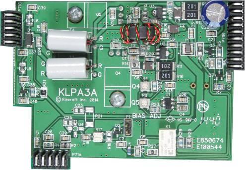
79 ILLUSTRATION DESCRIPTION QTY ELECRAFT PART NO. KLPA3A (Low Power Amplifier) PCB Assembly ESD Sensitive. 1 E K3S Mixer PCB Assembly ESD Sensitive. 1 E KNB3 Noise Blanker PCB Assembly ESD Sensitive. 1 E KREF3 PCB Assembly ESD Sensitive. 1 E A- 4


80 ILLUSTRATION DESCRIPTION QTY ELECRAFT PART NO. KSYN3A Assembly ESD Sensitive 1 E KIO3B Main PCB Assembly ESD Sensitive. 1 E KIO3B Audio I/O PCB Assembly ESD Sensitive. 1 E KIO3B Digital I/O PCB Assembly ESD Sensitive. 1 E KXV3B PCB Assembly ESD Sensitive. 1 E A- 5
 ILLUSTRATION")

 ILLUSTRATION")

81 Miscellaneous Components Packed in separate bags and envelopes as follows: E K3S Knobs for Front Panel (bag) ILLUSTRATION DESCRIPTION QTY ELECRAFT PART NO. Knob, VFO B Tuning 1 E Knob, RIT/XIT 1 E Knob, Concentric Shaft, Large 2 E Knob, Concentric Shaft, Small 2 E E K3S Front Panel Knobs, Set of 4 (bag) ILLUSTRATION DESCRIPTION QTY ELECRAFT PART NO. Knob, Small Encoder Shaft 4 E E K3S FP Encoder Assembly Bag ILLUSTRATION DESCRIPTION QTY ELECRAFT PART NO. K3S FP Encoder Assembly 2 E A- 6


, K3S 1 E100575 Bezel K3S 1 E100566")
 1 E850700 A- 7")
82 E K3S Knob and Band for VFO A (bag) ILLUSTRATION DESCRIPTION QTY ELECRAFT PART NO. Knob, VFO A Tuning 1 E Finger Grip, Main VFO Tuning Knob 1 E E K3S Front Panel Bezels and Serial Number Label (bag) ILLUSTRATION DESCRIPTION QTY ELECRAFT PART NO. Bezel Lens (LCD cover), K3S 1 E Bezel K3S 1 E Serial Number Label (supplied in envelope marked E850699) 1 E A- 7

83 E K3S RF Misc. Bag You will find bags included inside this bag. Where a bag or envelope inside this bag contain several parts with individual part numbers, they are listed on separate tables following this one. In addition there is a small bag marked K3S Hardware Spares Bag. It contains a collection of small parts that are easily lost. Normally you will not need any of the parts it contains to build your kit. ILLUSTRATION DESCRIPTION QTY ELECRAFT PART NO. TMP Cables, 5" (13 cm) 3 E Lithium Battery, 3V (in envelope) 1 E Loudspeaker Grill Cloth 1 E #4 Fiber Washer 4 E Front Feet with Stand Bottom Feet with tilt stand 1 E Rear Feet SO239 Hole Cover 1 E BNC Hole Cover 3 E Thumbscrew, #6 1 E D Fastener 10 E Thermal Insulator (inside small envelope) 2 E A- 8
84 ILLUSTRATION DESCRIPTION QTY Typical Standoffs ELECRAFT PART NO. (May be round or hexagonal) Standoff, 4-40, 1/4 (6.4 mm) long 6 E Standoff, 4-40, 3/8 (9.5 mm) long 2 E Standoff, 4-40, 1/2 (13 mm) long 3 E Typical Pan Head Screws Screw, 4-40, 1/4 (6.4 mm) Zinc, Pan Head 20 E Zinc Black Lock Washer #4, Split 36 E Lock Washer, #4, Interior Tooth 18 E Nut, E Washer, Flat, #6 2 E Grommet Bumper, 7/16 Round (Side panel feet) 4 E Coaxial Cable, TMP to 2 pin 1 E A- 9
 Black Pan Head 2 E700177 E850714 Stainless Steel (SS) Hardware (in K3S RF Misc Bag) ILLUSTRATION")
85 E KXV3B Hardware ILLUSTRATION DESCRIPTION QTY ELECRAFT PART NO. Lock Washer, #4, Internal Tooth 2 E Nut, Hex 2 E Screw, 4-40, 1/2" (13 mm) Black Pan Head 2 E E Stainless Steel (SS) Hardware (in K3S RF Misc Bag) ILLUSTRATION DESCRIPTION QTY Screw, 4-40, 3/16" (4.8 mm) Black Flat Head ELECRAFT PART NO. 26 E Typical Pan Head Screws Screw, 4-40, 3/8" (9.5 mm) Black Flat Head Screw, 4-40, 1/2" (13 mm) Black Flat Head Screw, 4-40, 7/16" (11 mm) Zinc Pan Head Screw, 4-40, 1/4" (6.4 mm) Black Pan Head 7 E E E E Zinc Black Screw. 4=40. 3/16" (4.8 mm) Black Pan Head 22 E Nut, Hex 10 E Lock Washer Internal Tooth 13 E Standoff, 4-40, 5/16"(7.9 mm) Long 1 E E Allen Wrench Envelope (in K3S RF Misc Bag) ILLUSTRATION DESCRIPTION QTY ELECRAFT PART NO. Allen Wrench, 5/64 (in envelope) 1 E Allen Wrench,.050 (in envelope) 1 E A- 10
86 E K144XV Side Panel Hardware Envelope (in K3S RF Misc Bag) ILLUSTRATION DESCRIPTION QTY ELECRAFT PART NO. Screw, 6-32, 1/4 (6.4 mm) Black Flat Head 3 E Lock Washer, #6, Internal Tooth 3 E Nut, E E KSYN3A Envelope (in K3S RF Misc Bag) ILLUSTRATION DESCRIPTION QTY ELECRAFT PART NO. Screw, /4 (6.4 mm) Zinc, Pan Head 2 E Lock Washer, #4, Internal Tooth 2 E E SO239 Ant Connector Assembly Bag (in K3S RF Misc Bag) ILLUSTRATION DESCRIPTION QTY SO239 (UHF) Female Panel Mount Connector with cable ELECRAFT PART NO. 1 E Screw, 4-40, 1/4 (6.4 mm) Black, Pan Head 4 E Lock Washer, #4, Interior Tooth 2 E Nut, E A- 11
 1 E700138 Typical Standoffs Standoff, 2/56, 5/16 (7.")
 long 3 E700003 Standoff, Nylon, 5/8 (15.9 mm) long 1 E700163 Screw, 4-40, 3/16 (4.")
 Zinc, Pan Head 1 E700173 2 E700124 9 E700005 Lock Washer, #2, Split 2 E700123 Lock Washer #4 Split 9 E700004 Nut, 1/2 (13")
87 E Front Panel Hardware Bag ILLUSTRATION DESCRIPTION QTY ELECRAFT PART NO. Felt Washer 3 E Knurled Nut (Phones Jack) 1 E Typical Standoffs Standoff, 2/56, 5/16 (7.9 mm) long 2 E Standoff, 4-40, 5/16 (7.9 mm) long 2 E Standoff, 4-40, 5/8 (15.9 mm) long 3 E Standoff, Nylon, 5/8 (15.9 mm) long 1 E Screw, 4-40, 3/16 (4.8 mm) Black, Flat Head Screw, 2-56, 1/4 (6.4 mm) Black, Pan Head Screw, 4-40, 1/4 (6.4 mm) Zinc, Pan Head 1 E E E Lock Washer, #2, Split 2 E Lock Washer #4 Split 9 E Nut, 1/2 (13 mm) Hex 6 E Lock Washer, 1/2 (13 mm) Interior Tooth 5 E Washer, Flat, Phones Jack Spacer 1 E (Soft Foam Strips) Front Panel Light Blocker (2 strips in envelope) 1 E A- 12
88 E LCD Bezel Screws (in Front Panel Hardware Bag) Do not mix these screws up with other parts in the Front Panel Hardware bag. Confusing them with other screws nearly the same length may destroy your front panel board. They are packaged separately for your convenience. You will be instructed when to use each screw in the assembly procedure. ILLUSTRATION DESCRIPTION QTY Screw, 4-40, 5/16 (7.9 mm) Black, Flat Head ELECRAFT PART NO. 1 E Screw, 2-56, 5/16" (7.9 mm) Fillister Head 2 E Screw, 2-56, 5/32" (6.4 mm) Fillister head 4 E E KIO3B Hardware Bag ILLUSTRATION DESCRIPTION QTY Screw, 4-40, 1/4 (6.4 mm) Black, Pan Head ELECRAFT PART NO. 2 E Screw, 4-40, 1/4 (6.4 mm) Zinc, Pan Head 2 E Lock Washer, #4, Interior Tooth 2 E Lock Washer #4 Split 2 E Jackscrew Nut, 4-40 Note: The jackscrew nuts may be mounted on the DB-9 connector on the Digital I/O Board. 2 E Standoff, 4-40, 1-1/4 (31.8 mm) long 2 E A- 13
 1")
89 E K3S RF BSF Assembly (in box) RF Board ESD Sensitive 1 E PA Jumper Block Assembly (pre-installed on RF board) 1 E A- 14


90 E K3S Chassis Set (in box) ILLUSTRATION DESCRIPTION QTY ELECRAFT PART NO. Front Panel 1 E100557SS Top Cover 1 E Rear Panel 1 E100214SS Front Panel Shield 1 E Chassis Stiffener 1 E KIO3B Digital I/O Panel In bag marked E E100558SS KXV3B Panel 1 E Loudspeaker with attached wire and connector 1 E Loudspeaker Shield 1 E A- 15
91 E Side Panels ILLUSTRATION DESCRIPTION QTY ELECRAFT PART NO. Left Side Panel 1 E Right Side Panel 1 E E Bottom Covers (Wrapped) ILLUSTRATION DESCRIPTION QTY ELECRAFT PART NO. Bottom Cover A 1 E Bottom Cover B 1 E E Carrying Handle Bag ILLUSTRATION DESCRIPTION QTY Handle (strap, spring insert and two end caps) ELECRAFT PART NO. 1 E Screw, 6-32, 1/2 (13 mm), Black, Pan Head (in envelope) 2 E Lock Washer, #6, Internal Tooth 2 E Nut, 6-32 (in envelope) 2 E A- 16


92 Cables in Separate Bags ILLUSTRATION DESCRIPTION QTY ELECRAFT PART NO. Power Cable APP and Ring Terminals 1 KPCA-F RJ-45 to DE-9S 1 E USB A-B Cable 1 E A- 17
ELECRAFT Application Note
 ELECRAFT Application Note Front Panel Microphone Circuit Modification Revision A, November 12, 2008 Copyright 2008, Elecraft, Inc., All Rights Reserved Background Some K3 owners have noted distorted transmit
ELECRAFT KXPA WATT AMPLIFIER KIT ASSEMBLY MANUAL. Revision A3, February 15, 2016 E Copyright 2016, Elecraft, Inc. All Rights Reserved
 ELECRAFT KXPA100 100-WATT AMPLIFIER KIT ASSEMBLY MANUAL Revision A3, February 15, 2016 E740221 Copyright 2016, Elecraft, Inc. All Rights Reserved Contents Introduction... 3 Customer Service and Support...
ELECRAFT K3 HIGH-PERFORMANCE METER TRANSCEIVER K3 KIT ASSEMBLY MANUAL. Rev M, September 3, 2014
 ELECRAFT K3 HIGH-PERFORMANCE 160 6 METER TRANSCEIVER K3 KIT ASSEMBLY MANUAL Rev M, September 3, 2014 Copyright 2014, Elecraft, Inc. All Rights Reserved Contents Introduction... 2 Customer Service and Support...
ELECRAFT KPA500 HIGH-PERFORMANCE METER AMPLIFIER KIT ASSEMBLY INSTRUCTIONS. Rev F2, December 7, 2012
 ELECRAFT KPA500 HIGH-PERFORMANCE 160 6 METER AMPLIFIER KIT ASSEMBLY INSTRUCTIONS Rev F2, December 7, 2012 Copyright 2012, Elecraft, Inc. All Rights Reserved Contents Introduction... 3 Customer Service
Elecraft KX3 KXFL3 Roofing Dual-Bandwidth Filter
 Introduction Elecraft KX3 KXFL3 Roofing Dual-Bandwidth Filter Installation and Calibration Instructions Revision A3, June 4, 2015 Copyright 2015, Elecraft, Inc., All Rights Reserved The KXFL3 is a high-performance,
TS-930: Installing the Inrad Roofing Filter Mod
 TS-930: Installing the Inrad Roofing Filter Mod The TS-930 roofing filter mod consists of a 6 pole, 4 to 5 khz wide filter followed by a high dynamic range, feedback amplifier. The amplifier provides enough
The ability to make basic voltage and resistance measurements using a digital multimeter
 Congratulations on your purchase of a new OneShot chassis! The PC01 OneShot combines a rugged enclosure, power supply, and discrete instrument DI in a compact 1/4U package. A few minutes of assembly are
E L E C R A F T K N B 1 N O I S E B L A N K E R
 Introduction E L E C R A F T K N B N O I S E B L A N K E R Assembly and Operating Instructions Revision C, Jan. 8, 200. Copyright 200, Elecraft; All Rights Reserved The KNB noise blanker can be used to
ELECRAFT AX-LINE OWNER S MANUAL AXB1 WHIP BIPOD AX1 DUAL BAND (+) WHIP ANTENNA AXT1 TRIPOD ADAPTER. Page 5. Page 2. Page 6
 WHIP ANTENNA AXT1 TRIPOD ADAPTER. Page 5. Page 2. Page 6") ELECRAFT AX-LINE OWNER S MANUAL AXB1 WHIP BIPOD Page 5 AX1 DUAL BAND (+) WHIP ANTENNA Page 2 AXT1 TRIPOD ADAPTER Page 6 E740330 Rev. B2, 4 Oct. 2018 Copyright 2018, Elecraft, Inc. All rights reserved 1
ELECRAFT AX-LINE OWNER S MANUAL AXB1 WHIP BIPOD Page 5 AX1 DUAL BAND (+) WHIP ANTENNA Page 2 AXT1 TRIPOD ADAPTER Page 6 E740330 Rev. B2, 4 Oct. 2018 Copyright 2018, Elecraft, Inc. All rights reserved 1
ELECRAFT KAT500 AUTOMATIC ANTENNA TUNER OWNER S MANUAL. Revision B5, December 21, Copyright 2012, Elecraft, Inc. All Rights Reserved
 ELECRAFT KAT500 AUTOMATIC ANTENNA TUNER OWNER S MANUAL Revision B5, December 21, 2012 Copyright 2012, Elecraft, Inc. All Rights Reserved Contents Introduction... 1 Quick Start... 1 Customer Service and
Ribcage Installation. Part 2 - Assembly. Back-Bone V1.06
 Ribcage Installation Part 2 - Assembly Back-Bone V1.06 Contents Section 1 Before You Get Started... 2 Included With Your Kit:... 2 Figure: A... 3 CAUTION!... 4 Note:... 4 Tools Required... 5 Section 2:
The Useless Machine. DIY Soldering Edition. Instruction Guide v0004
 The Useless Machine DIY Soldering Edition Instruction Guide v0004 TM For the best outcome, follow each step in order. We recommend reading this guide entirely before you get started. Tools required: Soldering
7878 K940. Checkpoint Antenna. Kit Instructions. Issue B
 7878 K940 Checkpoint Antenna Kit Instructions Issue B Revision Record Issue Date Remarks A July 7, 2009 First issue B Nov2013 Revised the Checkpoint installation procedures for 7878 and 7874 scanners Added
TS-870: Installing the Inrad Roofing Filter Mod
 TS-870: Installing the Inrad Roofing Filter Mod The TS-870 roofing filter mod consists of a 6 pole, 4 to 5 khz wide filter followed by a high dynamic range feedback amplifier. The amplifier provides enough
ELECRAFT KXPD1 PLUG-IN KEYER PADDLE
 Introduction ELECRAFT KXPD1 PLUG-IN KEYER PADDLE Assembly and Operating Instructions Revision B, July 27, 2011. Copyright 2011, Elecraft; All Rights Reserved The KXPD1 is a unique plug-in keyer paddle
INSTALLATION AND OPERATION MANUAL. Multiple-Radio Interface Module 41021G P-26 (11-12) 2012 David Clark Company Incorporated
 2012 David Clark Company Incorporated") INSTALLATI AND OPERATI MANUAL Multiple-Radio Interface Module 41021G-01 19537P-26 (11-12) 2012 David Clark Company Incorporated Table of Contents Cautions and Warnings... 1 Parts/Tools List... 2 Supplied
INSTALLATI AND OPERATI MANUAL Multiple-Radio Interface Module 41021G-01 19537P-26 (11-12) 2012 David Clark Company Incorporated Table of Contents Cautions and Warnings... 1 Parts/Tools List... 2 Supplied
HT-1A Dual Band CW QRP Transceiver. Kit Building Instructions
 HT-A Dual Band CW QRP Transceiver Kit Building Instructions Rev B, July 8, 08 Designed by BD4RG Exclusively distributed by CRKITS.COM and its worldwide distributors Join the group http://groups.io/g/crkits
ELECRAFT KAT500 AUTOMATIC ANTENNA TUNER OWNER S MANUAL. Revision C6, March 8, Copyright 2017, Elecraft, Inc. All Rights Reserved E740183
 ELECRAFT KAT500 AUTOMATIC ANTENNA TUNER OWNER S MANUAL Revision C6, March 8, 2017 E740183 Copyright 2017, Elecraft, Inc. All Rights Reserved Contents Introduction... 1 Quick Start... 1 Customer Service
Assembly Instructions
 Assembly Instructions For the SSQ-2F 3.1 MHz Rife Controller Board Kit v1.41 Manual v1.00 2012 by Ralph Hartwell Spectrotek Services GENERAL ASSEMBLY INSTRUCTIONS Arrange for a clean work surface with
SDR Cube Transceiver Online Assembly Guide
 SDR Cube Transceiver Online Assembly Guide Detailed construction notes for building and testing each of the SDR Cube kit modules Home Bill of Materials I/O Board Controls Board DSP Board Softrock SR-Base
WA3RNC 30 METER CRYSTALPLEXER TRANSMITTER KIT ASSEMBLY INSTRUCTIONS
 WA3RNC 30 METER CRYSTALPLEXER TRANSMITTER KIT ASSEMBLY INSTRUCTIONS Description The WA3RNC 30 Meter Crystalplexer is a low power crystal controlled QRP transmitter offering a significantly improved tuning
FMR622S DUAL NARROW BAND SLIDING DE-EMPHASIS DEMODULATOR INSTRUCTION BOOK IB
 FMR622S DUAL NARROW BAND SLIDING DE-EMPHASIS DEMODULATOR INSTRUCTION BOOK IB 1222-22 TABLE OF CONTENTS SECTION 1.0 INTRODUCTION 2.0 INSTALLATION & OPERATING INSTRUCTIONS 3.0 SPECIFICATIONS 4.0 FUNCTIONAL
Assembly Instructions for the 1.5 Watt Amplifier Kit
 Assembly Instructions for the 1.5 Watt Amplifier Kit 1.) All of the small parts are attached to a sheet of paper indicating both their value and id. 2.) Leave the parts affixed to the paper until you are
model tsa-sa48 Sliding Crosscut Table installation guide
 model tsa-sa48 Sliding Crosscut Table installation guide A Note About Color Variations Among Anodized Aluminum Components Congratulations on the purchase of this SawStop Sliding Crosscut Table. We at SawStop
TS-850: Installing the Inrad Roofing Filter Mod
 TS-850: Installing the Inrad Roofing Filter Mod The TS-850 Roofing Filter Mod consists of a 6 pole, 4 to 5 khz wide filter followed by a high dynamic range feedback amplifier. The amplifier provides enough
IC-781: Installing the Inrad Roofing Filter Mod
 IC-781: Installing the Inrad Roofing Filter Mod The Icom IC-781 roofing filter mod consists of a 6-pole, 4 to 5 khz wide filter followed by a high dynamic range, feedback amplifier. The amplifier provides
Read Below! Read Below! Read Below! Read Below! Read Below! Read Below! STOP READ TIPS BELOW TO MAKE ASSEMBLY MUCH EASIER
 Read Below! Read Below! Read Below! Read Below! Read Below! Read Below! STOP READ TIPS BELOW TO MAKE ASSEMBLY MUCH EASIER Here are some guidelines to help make assembling your unit much easier: -Read and
Assembly Instructions for the FRB FET FM 70 Watt Amp
 Assembly Instructions for the FRB FET FM 70 Watt Amp 1.) Orient the circuit board with the diagram 2.) Use a narrow chisel tip 25-30 watt soldering iron for assembly 3.) All the small parts are taped onto
DEM Part Number L144-28INTCK 144 MHz Transverter Kit and complete kit
 DEM Part Number L144-28INTCK 144 MHz Transverter Kit and complete kit Power Out: Noise Figure and Gain: DC Power Requirement: 50 mw linear minimum 3.5 db NF nominal, 5 dbg maximum 12-15.5 VDC, 13.8 nominal
Electric Guitar Kit DC Style electric guitar kit
 Electric Guitar Kit DC Style electric guitar kit user manual Musikhaus Thomann Thomann GmbH Hans-Thomann-Straße 1 96138 Burgebrach Germany Telephone: +49 (0) 9546 9223-0 E-mail: info@thomann.de Internet:
Sunset Swings By Health in Motion, LLC
 Sunset Swings By Health in Motion, LLC Model 421 Lounge Swing Assembly and Operation Manual Record Serial Number Here www.sunsetswings.com by Health In Motion, LLC. 11/6/2009 421 Owners Assembly and Operation
Assembly and Operating Instructions. Revision D, Aug. 20, Copyright 2002, Elecraft; All Rights Reserved
 Introduction E L E C R A F T K N B N O I S E B L A N K E R Assembly and Operating Instructions Revision D, Aug. 0, 00. Copyright 00, Elecraft; All Rights Reserved The KNB noise blanker can be used to suppress
Assembly Instructions and Parts Manual JPSF-1 Fence and JPSR Rail Set
 Assembly Instructions and Parts Manual JPSF-1 Fence and JPSR Rail Set WALTER MEIER (Manufacturing) Inc. 427 New Sanford Road LaVergne, Tennessee 37086 Part No. M-708482 Ph.: 800-274-6848 Revision C2 02/2013
ABM International, Inc.
 ABM International, Inc. Lightning Stitch required 1 1.0: Parts List head and motor assembly (Qty. 1) Reel stand (Qty. 1) Needle bar frame clamp (Qty. 1) Motor drive (Qty. 1) 2 Cable harness with bracket
TS-950: Installing the Roofing Filter Mod
 TS-950: Installing the Roofing Filter Mod The Kenwood TS-950 Roofing Filter Mod consists of a 6 pole, 4 to 5 khz wide filter followed by a high dynamic range feedback amplifier. The amplifier provides
Sliding Crosscut Table installation guide
 Sliding Crosscut Table installation guide model tsa-sa48 A Note About Color Variations Among Anodized Aluminum Components Congratulations on the purchase of this SawStop Sliding Crosscut Table. We at SawStop
EmagiKit. Privacy Pod Plus. Quiet. Easy. Affordable. INSTRUCTIONS ASSEMBLY
 EmagiKit Privacy Pod Plus Quiet. Easy. Affordable. INSTRUCTIONS ASSEMBLY DIMENSIONS AND COMPONENTS 47 47 Ceiling Unit 2-B 2-L 2-R Glass Door Corner Trim Door Handle 90 Adjustable Height Work Surface 1-B
Customer Notice: Congratulations again on your SawStop purchase, and thank you! -SawStop Tualatin, OR
 Customer Notice: Congratulations on the purchase of this Sliding Crosscut Attachment. As the owner of a SawStop saw, you are familiar with our high standards for quality, fit and finish. Different from
Hatchback Wing Riser Kit
 Hatchback Wing Riser Kit 2015-06-11 Thank you for purchasing this PERRIN product for your car! Installation of this product should only be performed by persons experienced with installation of aftermarket
High Rise Sit-Stand Desk Converter
 High Rise Sit-Stand Desk Converter Assembly Instructions for Model DC350 Patent No. 9,332,839 PRE-ASSEMBLY Please read all instructions before beginning assembly. We strongly recommend you watch the video
Spiderbeam Balun Construction Guide
 BALUN CONSTRUCTION GUIDE Ver. 1.0 1 The components of the Balun Kit are in a plastic bag. Most of the components are inside the plastic case of the balun. The aluminum U-profile and the RG-142 Teflon Coax
SoftRock v6.0 Builder s Notes. May 22, 2006
 SoftRock v6.0 Builder s Notes May 22, 2006 Be sure to use a grounded tip soldering iron in building the v6.0 SoftRock circuit board. The soldering iron needs to have a small tip, (0.05-0.1 inch diameter),
DEC-001 Installation Instructions
 DEC-001 Installation Instructions Skill Level: The installation of this assembly requires a medium level of expertise in working with modern electronic equipment. The use of appropriate tools, correct
LEG CURL IP-S1315 INSTALLATION INSTRUCTIONS
 LEG CURL IP-S35 INSTALLATION INSTRUCTIONS Copyright 2009. Star Trac by Unisen, Inc. All rights reserved, including those to reproduce this book or parts thereof in any form without first obtaining written
PULL-THRU USER S MANUAL
 PULL-THRU USER S MANUAL G14x Part # 310 120 177 G20 Part # 310 120 188 G20x Part # 310 120 186 G40x Part # 310 120 163 TABLE OF CONTENTS SECTION 1 PCB DESIGN AND MOUNTING SECTION 2 MOUNTING ADAPTER TO
INTERNATIONAL RADIO CORP
 I N R A D INTERNATIONAL RADIO CORP 13620 Tyee Road Umpqua, OR 97486 (541) 459-5623 fax (541) 459 5632 E-mail: inrad@rosenet.net www.qth.com/inrad IC-775 ROOFING FILTER INSTALLATION INSTRUCTIONS The IC-775
U.S. Rack, Inc Falcon Drive, Madera, CA APR17 INSTALLATION AND USE INSTRUCTIONS for SIDE-MOUNT LADDER RACK
 U.S. Rack, Inc. 2850 Falcon Drive, Madera, CA 93637 15APR17 INSTALLATION AND USE INSTRUCTIONS for SIDE-MOUNT LADDER RACK WARNING: Do NOT attempt to install or use this rack without following all instructions.
KX2 Side KX installation
 KX2 Side KX installation NOTE: The installation of any Side KX parts does NOT require the unsoldering of any connection nor removal of ANY of the boards from within the radio! The user/installer assumes
Custom Front Panel Upgrade Instructions
 Custom Front Panel Upgrade Instructions Here are the directions for upgrading your SP-II to an SP-IIB, with a custom blackanodized front panel and engraved lettering. There are only forty SP-IIB s in existence
Building the Toothpick Audio CW Filter
 Building the Toothpick Audio CW Filter Introduction The toothpick is a simple variable bandpass audio filter designed to compliment the Splinter QRPp Trans-Receiver. The filter also contains an audio amplifier
IC-765: Installing the Inrad Roofing Filter Mod
 IC-765: Installing the Inrad Roofing Filter Mod The Icom IC-765 roofing filter mod consists of a 6-pole, 4 khz wide filter followed by a high dynamic range, feedback amplifier. The amplifier provides enough
K1FO 12 ELEMENT 144/147 MHz YAGI
 K1FO 12 ELEMENT 144/147 MHz YAGI WARNING: INSTALLATION OF THIS PRODUCT NEAR POWER LINES IS DANGEROUS. FOR YOUR SAFETY FOLLOW THE INSTALLATION DIRECTIONS. Ariane Arrays, Inc. Copyright 2006 201 Hopedale
PEDAL TIMPANI. TP3300 series TP3323 / TP3326 / TP3329 / TP3332. Owner s Manual
 PEDAL TIMPANI TP3300 series TP3323 / TP3326 / TP3329 / TP3332 Owner s Manual English Thank you for purchasing Yamaha Timpani. Please read through this manual carefully as it contains important information
Assembly Instructions and Parts Manual JPSF-1 Fence and JPSR Rail Set #
 Assembly Instructions and Parts Manual JPSF-1 Fence and JPSR Rail Set #1002493 JET 427 New Sanford Road LaVergne, Tennessee 37086 Part No. M-708482 Ph.: 800-274-6848 Revision C3 02/2014 www.jettools.com
SawStop. T-GlideTM. Fence System- Professional Series II OWNER S MANUAL
 SawStop T-GlideTM Fence System- Professional Series II OWNER S MANUAL Warranty SawStop warrants to the original retail purchaser of a new T-Glide Fence System - Professional Series II from an authorized
STRINGING MACHINE OWNER'S MANUAL. Copyright 1998 GAMMA Sports - All Rights Reserved
 6002 STRINGING MACHINE OWNER'S MANUAL Issue 3 - June 20, 1998 Copyright 1998 GAMMA Sports - All Rights Reserved 6002 OWNER'S MANUAL TABLE OF CONTENTS PAGE 1... WARRANTY PAGE 2... FEATURES PAGE 3... ASSEMBLY
OpenROV. Guide 3 - Electronics. We will now move to the assembly of the electronics that will control the ROV. Written By: OpenROV
 OpenROV Guide 3 - Electronics We will now move to the assembly of the electronics that will control the ROV. Written By: OpenROV 2017 openrov.dozuki.com Page 1 of 33 INTRODUCTION We will introduce soldering
S-Pixie QRP Kit. Student Manual. Revision V 1-0
 S-Pixie QRP Kit Student Manual Revision V 1-0 Introduction The Pixie 2 is a small, versatile radio transceiver that is very popular with QRP (low power) amateur radio operators the world over. It reflects
Assembly Instructions 10 X 10 Aluminum Frame Building
 Assembly Instructions 10 X 10 Aluminum Frame Building 27 97 9 8 47 36 74 52 10 10 X 10 Square Building W/ Dome Includes: The Steel Entry Door with a Dead Bolt Lock assembly and Aluminum Door Frame. Metal
Lumber Smith. Assembly Manual. If you are having problems assembling the saw and need assistance, please contact us at:
 Lumber Smith Assembly Manual If you are having problems assembling the saw and need assistance, please contact us at: 804-577-7398 info@lumbersmith.com 1 Step 1 Safety Carefully read the Owners Manual.
REP Design LLC. 193 Winding Ridge Rd, Southington, CT INSTALLATION INSTRUCTIONS:
 REP Design LLC 193 Winding Ridge Rd, Southington, CT 06489 1-860.426.1894 n7emw@cox.net www.repdesign.us INSTALLATION INSTRUCTIONS: SHD-SO239 Super Heavy Duty SO-239Antenna Mounting System Thank you for
Written By: Andrew Optimus Goldberg
 Replace the screen your GSM/AT&T iphone 4. Written By: Andrew Optimus Goldberg ifixit CC BY-NC-SA www.ifixit.com Page 1 of 25 INTRODUCTION [video: http://www.youtube.com/watch?v=obpfpfx5abw] Use this guide
Riverside. Windward Bay EntertaInment Wall System Assembly Instructions. Made In Viet Nam. Right Pier. Bridge & Back Panel.
 EntertaInment Wall System Page 1 of 12 Product No. 42840 42848 42849 42843 Product Description Console Left Pier Right Pier Bridge & Back Panel Right Pier Bridge & Back Panel Left Pier 63" Inch Ent. Console
Model 2740B High Security Safe Lock. Installation Instructions. Mounting Considerations:
 Model 2740B High Security Safe Lock Installation Instructions Mounting Considerations: The Sargent & Greenleaf 2740B safe lock is designed to use the same mounting screw locations as common S&G mechanical
PHG-1000X. Owner s Manual HOME GYM
 HOME GYM Owner s Manual WWW.BODYSOLID.COM THERE IS A RISK ASSUMED BY INDIVIDUALS WHO USE THIS TYPE OF EQUIPMENT. TO MINIMIZE RISK, YOU MUST FOLLOW THESE RULES:! " # $ % & ' ( ) * + ' (, ' " -. *, * ) )
Starving Student II. Starving Student II. SS2 guide. Written By: 6L guides.diyaudio.com/ Page 1 of 24
 SS2 guide Written By: 6L6 2019 guides.diyaudio.com/ Page 1 of 24 INTRODUCTION This is a build guide for the hybrid headphone/pre-amplifier. You can buy a kit at the SSII product listing on the diyaudio
BAND DECODER and CONTROLLE R. Accessibility Upgrade and Operating Instructions
 ELE CRAFT KRC2 BAND DECODER and CONTROLLE R Accessibility Upgrade and Operating Instructions Revision A, March 4, 2004. Copyright 2004, Elecraft; All Rights Reserved Introduction The KRC2 Accessibility
Elecraft KX3 KX3-2M 2-Meter and KX3-4M 4-Meter Transverter Options
 Elecraft KX3 KX3-2M 2-Meter and KX3-4M 4-Meter Transverter Options Installation and Operating Instructions Revision A5, September 5, 2014 Copyright 2014, Elecraft, Inc., All Rights Reserved Introduction...
KN-Q10 Assembly Manual
 KN-Q10 Assembly Manual Translated by Adam Rong, BD6CR/4 with permission from Ke Shi, BA6BF Edited by Stephen, VK2RH Revision B, Oct 14, 2010 Thank you for purchasing the KN-Q10 4 Band SSB/CW Dual Mode
Hollywood Swing Away 2 and 4 Bike Racks Assembly and Installation Guide
 Hollywood Swing Away 2 and 4 Bike Racks Assembly and Installation Guide Tools Required: two adjustable wrenches, pliers, ¾ socket wrench recommended Note: please do assembly near your vehicle as you Can
Installation & Operation Manual SAGA1-K Series Industrial Radio Remote Control
 Installation & Operation Manual SAGA1-K Series Industrial Radio Remote Control Gain Electronic Co. Ltd. Table Of Contents Safety Considerations ------------------------------------------------------------2
KN-8828B Upgrade Directions
 KN-8828B Upgrade Directions This document outlines the steps to take to update earlier Hottop Bean Roasters to the KN-8828B 2007 by Chang Yue and Hottop USA - All Rights Reserved No part of this document
Pingable Envelope Generator
 Pingable Envelope Generator Kit Builder's Guide for PCB v1.0.3 4mspedals.com PEG This guide is for building a Pingable Envelope Generator (PEG), which is an intermediate-level kit. You should be confident
MOTOR & BULK HEAD. A Manual for Repair and Maintenance Technicians
 MOTOR & BULK HEAD A Manual for Repair and Maintenance Technicians CAUTION This manual is designed to help technicians who are already experienced in workshop procedures and know how to handle tools. Only
Cricket 80a Assembly Manual v Copyright David Cripe NM0S The 4 State QRP Group
 Cricket 80a Assembly Manual v. 1.0 Copyright 2017 David Cripe NM0S The 4 State QRP Group Introduction Thank you for purchasing a CRICKET 80a Transceiver. We hope you will enjoy building it and find it
Print Head Installation Guide
 Print Head Installation Guide MCS Raptor 6 (MCS Eagle AMS Software) is copyright of MCS Incorporated. 2015 MCS Incorporated. 1 Contents Tools... 4 Warnings... 4 Introduction... 4 Section One - Pillar Installation...
OWNER S MANUAL CONTENTS. The only table saw fence with Automatic Positioning Control TM
 The only table saw fence with Automatic Positioning Control TM OWNER S MANUAL Please read this owner s manual before use and keep it at hand for reference. Note: The INCRA TS II system consists of three
Signal Mirror Installation Instructions Toyota Tacoma
 Signal Mirror Installation Instructions 2005-2015 Toyota Tacoma THE safety accessory of the 21 st Century. P/N 210-0115-0 Rev. A4 (3/11/15), BTV 2005 Muth Mirror Systems, LLC Page 3 of 12PplPage 3 of 12
Custom Pendant- Hardwire Assembly and Installation Instructions
 Custom Pendant- Hardwire Assembly and Installation Instructions CAUTION: BEFORE INSTALLING FIXTURE, MAKE SURE THE POWER TO THE CIRCUIT IS TURNED OFF AT THE MAIN FUSE BOX / CIRCUIT BREAKER UTILITY BOX.
2-Door EXO-Top Roof Rack System
 Page 1/29 Part 13516.01 2-Door EXO-Top Roof Rack System! WARNING The EXO-Top Roof Rack System is rated to a dynamic 300 lb, evenly distributed load. Further loading could result in serious injury or death.
Instructions to Convert a 4-foot Florescent Fixture to LEDs Using 60W Power Supply Using 2 or 3 strips 30Dec15
 Instructions to Convert a 4-foot Florescent Fixture to LEDs Using 60W Power Supply Using 2 or 3 strips 30Dec15 Thank you for purchasing the Shoplight Solutions 4-ft conversion kit. This is a companion
JK Rear Crusher Flares
 INSTALLATION INSTRUCTIONS INST-17-05-010_A JK Rear Crusher Flares IMPORTANT: Thank you for purchasing this Poison Spyder product. Please read through this entire document before proceeding with installation.
Value Location Qty Transistors 2N5485 Q1, Q2, 4 Q3, Q4 2N5087 Q5 1. Trim Pots 250k VTRIM 1. Potentiometers C500k Speed 1. Toggle Switch On/On Vibe 1
 P-90 BUILD INSTRUCTIONS Thank you for your purchase of our P-90 kit! We have completely redesigned our entire line of kits to be the most user friendly, while still maintaining their same great sound!
Installing and Upgrading Internal Modules in Cisco 1800 Series Routers (Modular)
") CHAPTER Installing and Upgrading Internal Modules in Cisco 800 Series Routers (Modular) This chapter describes how to install or upgrade modules that are located internally within the Cisco 800 series
CHAPTER Installing and Upgrading Internal Modules in Cisco 800 Series Routers (Modular) This chapter describes how to install or upgrade modules that are located internally within the Cisco 800 series
Build your own. Stages 7-10: See Robi s head move for the first time
 Build your own Pack 03 Stages 7-10: See Robi s head move for the first time Build your own All rights reserved 2015 Published in the UK by De Agostini UK Ltd, Battersea Studios 2, 82 Silverthorne Road,
Value Location Qty Potentiometers C1M Distortion 1 A10k Volume 1. Footswitch 3PDT SW1 1. Jacks 1/4 Mono 2 DC Power 1
 Distortion BUILD INSTRUCTIONS Thank you for your purchase of our Distortion+ kit! We have completely redesigned our entire line of kits to be the most user friendly, while still maintaining their same
Pacific Antenna Field Strength Indicator Kit
 Pacific Antenna Field Strength Indicator Kit Description The Field Strength Indicator kit from Pacific Antenna provides a visual way to monitor the presence and relative strength RF fields through the
OWNER S MANUAL. Safety. Please read this owner s manual before use and keep it at hand for reference. Warranty
 Please read this owner s manual before use and keep it at hand for reference. OWNER S MANUAL Safety Important safety instructions for using the INCRA Miter5000 Before using the INCRA Miter5000, read and
Volvo 240/260 New Face Overlay Installation Models By Dave Barton
 Volvo 240/260 New Face Overlay Installation 1975-80 Models By Dave Barton These custom faces are the product of years of research and experimentation. They are printed with a special printer using waterproof
Please Do Not Return This Product To The Store!
 MODEL NO. T8176 QUICK SERVE 3000 TABLE TENNIS TABLE OWNER'S MANUAL 1. Read this manual carefully before starting assembly. Read each step completely before beginning each step. 2. Some smaller parts may
MEC Auto-Mate Assembly Manual. For MEC 9000G/GN and 8567 Grabber Series
 MEC Auto-Mate Assembly Manual For MEC 9000G/GN and 8567 Grabber Series Thank you We really appreciate your support of our product line. But our commitment to you hardly ends here. We won't be satisfied
Please Do Not Return This Product To The Store!
 MODEL NOS. T81 TABLE TENNIS TABLE OWNER'S MANUAL 1. Read this manual carefully before starting assembly. Read each step completely before beginning each step.. Some smaller parts may be shipped inside
General Prisoner Transport Install Instructions PT-2-INST
 General Prisoner Transport Install Instructions PT-2-INST 50 or 60 high x 80, 100 & 120 inch long / Double Compartment Inserts Also refer to PT-A-3XX instructions for vehicle specific mounting measurements
LDB-1 Kit Instructions Page 1 of 8
 LDB-1 Kit Instructions Page 1 of 8 Important Information Congratulations and thank you for your purchase of the LDB-1 Little Drummer Boy Analog Drum Machine Kit! Before you start, please read the enclosed
Warnings. Description. Prior to Installation Tools Needed
 Warnings Failure to act in accordance with the following may result in death or personal injury. The JT Strong Arm Stabilizer System is intended to eliminate chassis movement in travel trailers and fifth
On a modular synthesizer, attenuators are an important building block in pretty much every part of your patch for both CV and audio duties.
 OVERVIEW For the most recent version of this document please visit www.thonk.co.uk For all technical support please visit http://bit.ly/r0nqyt on Muffwiggler. The Thonk AT-AT-AT Triple Passive Attenuator
Pacific Antenna Low Pass Filter Kit
 Pacific Antenna Low Pass Filter Kit Description Many basic transmitter and/or transceiver designs have minimal filtering on their output and frequently have significant harmonic content in their signals.
SIMPLEX ELITE MAT CUTTER
 INSTRUCTION MANUAL MODEL 750-1 / 760-1 SIMPLEX ELITE MAT CUTTER INSTRUCTIONS AND OPERATION MANUAL 40 in (101 cm) mat cutting system with bevel & straight cutters, production stops, 27 in (68 cm) squaring
Fiber Splice Box (FSB-D) Installation Instructions
 Installation Instructions") Fiber Splice Box (FSB-D) Installation Instructions Table of Contents General Product Information... 1.0 Safety Precautions... 2.0 Tools Required... 3.0 Package Contents... 4.0 Installing the Product Unpacking...
Fiber Splice Box (FSB-D) Installation Instructions Table of Contents General Product Information... 1.0 Safety Precautions... 2.0 Tools Required... 3.0 Package Contents... 4.0 Installing the Product Unpacking...
Steele TV Stand Stock # BH
 LOT NUMBER: DATE PURCHASED: / / Steele TV Stand Stock # BH46-084-899-02 ADULT ASSEMBLY REQUIRED If you have any questions regarding assembly or if parts are missing, DO NOT return this item to the store