Lockformer / 16 Gauge Speednotch
|
|
|
- Merryl Fisher
- 6 years ago
- Views:
Transcription
1 Lockformer / 16 Gauge Speednotch INSTALLATION PRELIMINARY: After uncrating, locate unit, with or without base skid, to area of operation. Unbind foot switch cord and cylinder hoses and remove gauge pin bag. ELECTRICALS: Remove manual starter box cover and wire unit as per diagram illustrated on inside of cover. Normal electrics 220 volt, 60 cycle, 3 phase with overload protection in starter box. Motor furnished -3 H.P. x 1800 RPM. IMPORTANT: When starting unit check to see whether motor and pump rotation conforms to direction of arrows on motor and pump body. CAUTION: Jog unit until proper rotation is achieved. Severe damage to pump will result if run backward to rotation shown. OPERATING INSTRUCTIONS CAPACITY: 16 gauge or lighter galvanized or cold rolled steel. OPERATION: Loosen left hand notching head and slide to zero mark on Back Scale, clamp into position. Move vee notching heads to required spacing by locating left side of heads to required measurement from zero on scale. EXAMPLE: 4 x 12 DUCT in 22 gauge material - one piece construction. PROCEDURE: (1) Left forming head set at zero. NOTE width of notch required for 5/16" Pittsburgh lock is 1", therefore, a full pin is required in hole indicated as 1 on width of notch sketch. Using standard S Cleats and Drive Cleats would require a minimum depth of notch to be 1, therefore, a half pin is required in hole indicated as 1" on depth of notch sketch. (See Sketch No. 1) (2) Move first Vee notch head to either 4" or 12 on tape and secure. (3) Move second Vee notch head to 16" and secure. (NOTE: = 16 )
2 (4) Move third Vee notch head to 20 or 28 dependent on setting of first Vee notching head. (NOTE: = 20 or = 28 ) (5) Move right hand notching head to required notch depth of ¼ for right angle flange. NOTE: Place gauge pin into hole for gauging setup piece. Pin may be removed for easier gauging on similar size sheets. Place back gauge pin into proper hole 1 fir depth of notch. Place proper width of material 33-1/4 (for 22 gauge 4 x 12 one piece duct using 5/16" Pittsburgh Lock and ¼ 90º Flange) onto gauge. support table and square duct to gauge pins. Activate notching heads by depressing foot switch until notching is completed. Release foot switch and remove completely notched duct sheet. CAUTION: Release foot switch immediately after cutting is completed. If foot switch is kept depressed oil pressure will be at maximum setting of relief valve and will cause unnecessary heating of oil and possible damage to pump. Notching heads will notch the equivelant of 16 ga. material (.062), therefore, more than one thickness of lighter gauge materials can be notched in one operation, provided combined thickness does not exceed.062. NOTE: When two piece duct construction is manufactured, the notching heads that are not required can be quickly deactivated by removing the notching head hose drawing back on the quick disconnect coupling at the manifold. This makes heads not required inoperative. OIL: The oil used in the reservoir is a commercial hydraulic oil having a viscosity of 150 SSU at 1000 F. On initial fill 7 U.S. gallons Socony Vacuum D.T.E. Light- is delivered in the reservoir. An acceptable substitute for above hydraulic oil is Type A automatic transmission fluid, available at auto service stations. For proper maintenance of the hydraulic system, the oil should be kept clean and free of dirt or other foreign matter. The system should be changed after approximately one year's operation. This is accomplished by rem %,ing drain plug at bottom of reservoir. Replace and fill with clean filtered oil. A ruler inserted to bottom of reservoir will indicate 7" when proper oil level is reached. DIE CARE AND MAINTENANCE: Punch and dies are manufactured of high carbon high chrome tool steel for maximum cutting service. When die cutting surfaces become wom it will be necessary to resharpen. Lower dies are held in position by socket-head cap screws and may be easily removed. To remove punch, disconnect hose from manifold and remove head from back gauge bar by removing assembly parts #109 & #110, place unit in vise and remove lower bottom cap (#107) and spring #105. Place pin into assembly hole in piston (Part #102). Using a 15/16' socket and extension wrench remove 5/8 hexagon nut #127. Slide parts #126 lock washer, #104 guide washer and punch #1 16
3 from piston rod. NOTE: It may become necessary to push piston farther into cylinder body #100 in order to clear punch from the piston rod. NOTE: When punch and dies are to be sharpened in the field, grind flat top surface of die and lower cutting surface of punch. You will note punch has rake angle. This rake angle must be maintained. A LIGHT OIL SHOULD BE APPLIED OCCASIONALLY TO CUTTING SURFACE OF PUNCH AND DIE TO PROLONG DIE LIFE REASSEMBLE AS FOLLOWS: Place punch, backing washer, lock washer and nut into assembly and tighten securely with pin in piston assembly hole to keep piston from turning when tightening. Pull piston to lowest position and assemble die to cylinder body, nesting die to punch for proper alignment and clearance. NOTE: A slight clearance, not to exceed 0.003", should be set between punch and die on VEE-NOTCH by placing a 0.003" to " spacer shim on both sides of cutting edge of dies. Tighten the socket-head cap screw vl29. For CORNER NOTCH punch and dies, the clearance should be 0.005". (FOLLOW SAME PROCEDURE AS ABOVE FOR REASSEMBLY.) After the above has been completed, replace spring and lower bottom cap, tighten and reassemble to machine. PARTS LIST AND DESCRIPTION OF HEAD AND DIE ASSEMBLY PLEASE USE NEW NUMBER WHEN ORDERING PARTS. New Pieces Part Description Per Unil No Cylinder Head Piston Backing Plate Backing Plate Left Backing Plate Right Guide Washer Compression Spring Spring Guide Bottom Cap Stud Cylinder Clamp Handle Gib Left Gib Right Guide Plate /4 x 3/4 Dowel Pin Gauge Step Pin Punch Die Vee Punch Left Die Left Punch Right Die Right /4 Straight Elbow /4 x 1 Nipple Rings /16 X 1 Roll Pin /8 Lock Washer /8-11 Hex Nut Finished 15/ /4-28 x 3/8 SH Cap Screw /4 Swivel Adaptor /8-16 x 3/4 SHCS /4-28 x 1/2 HH Cap Screw /4-28 X 5/16 Socket Set Screw Ball Valves 5
4

5
6
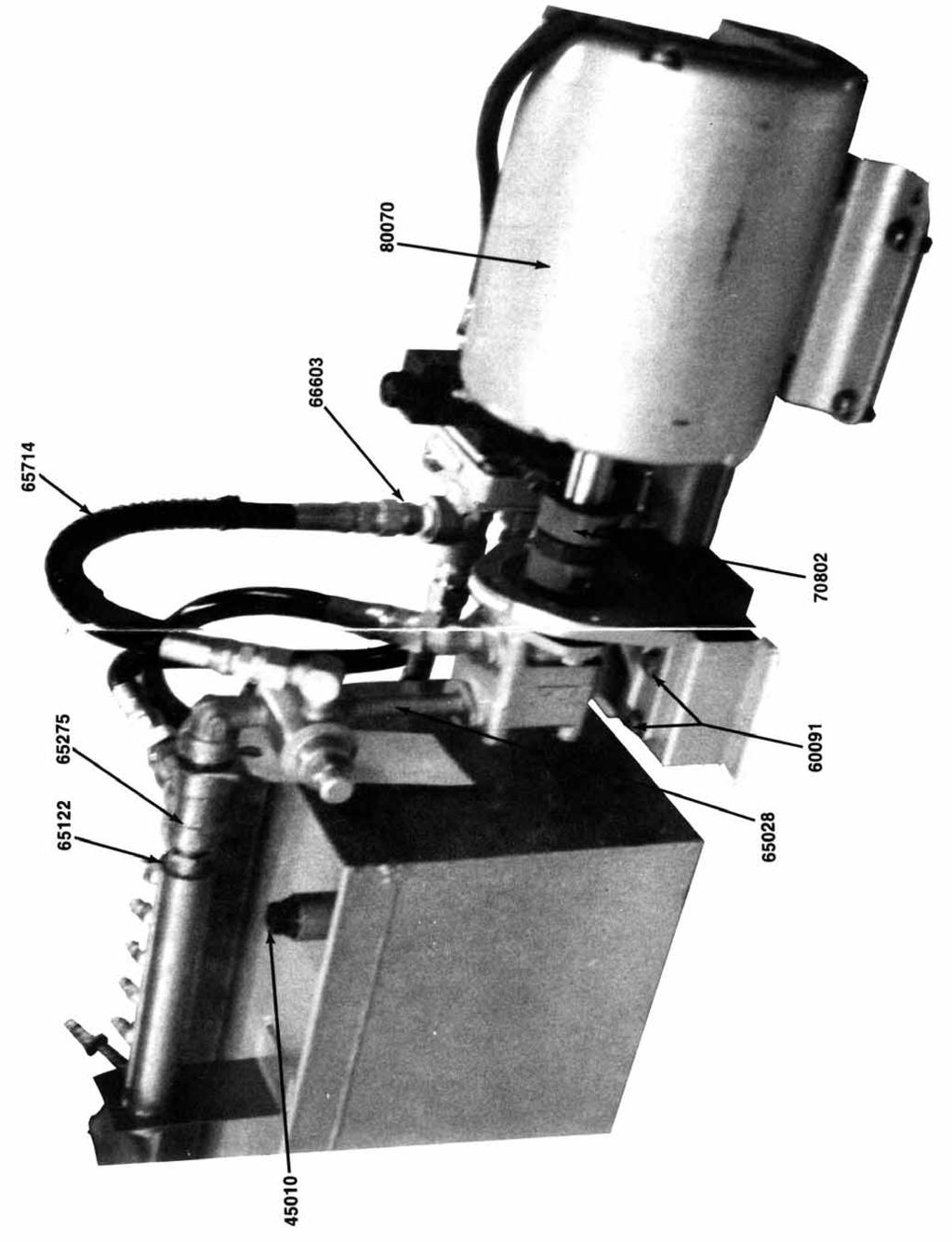
7 PARTS LIST AND DESCRIPTION LOCKFORMER SPEEDNOTCH PLEASE USE NEW NUMBER WHEN ORDERING PARTS. New Pieces Part Description Per Unit No Adaptor-Straight Adaptor - 90 degree elbow Hose Hose Hose Adaptor - 45 degree elbow /4 x 1/2 Hex Bushing /8 x 3 3/4 Nipple /2 x 3/8 Hex Bushing /2 Straight Elbow /2 Close Heavy Nipple Vent Pipe Plug HP Motor Control x 8 Cord Cord W49 Heater Element BX Cable BX Connector BX Elbow Connector Foot Switch Hydraulic Pump Valve - Relief Solenoid Valve Valve Sub Plate Manifold Coupling Cover /4 Plug /4 Nipple SHPP 1 New Pieces Part Description Per Unit No Hose /16-18 x 5/16 SSS Work Guide Assembly /8 x 1/16 Washer /8-16 x 1 3/4 HH Cap Screw /8-16 x 1 1/4 HH Cap Screw /8-16 Heavy Hex Nut /8-16 Hex Nuts - Finished /8 Lock Washer x 1/2 RHMS /16 Lock Washer /8 x.052 Washers x 3/16 Drive Screw TP-U G300 Coupling /2 Nipple Form Screws /8-16 x I HH Cap Screw /4-20 x 3/4 SH Cap Screw /4-20 x 11/2 SH Cap Screw x % Round Head Machine Screw Hex Nut /2 x 1/2 x 1/2 Tee Wire Nut Terminal Wire Joint Lockformer Logo Caution Tag Stand Assembly /4-10 x 3 1/2 HH Cap Screw Foot Tape Measure Double Faced Packing Tape Hydraulic Tank Assembly 1 16 GAUGE SPEEDNOTCH SERIAL NO. VG 2042 & FOLLOWING /4 x 1 Heavy Nipple /4 x Swivel Adaptor Shut Off Valve 5 16 GAUGE SPEEDNOTCH SERIAL NO. VG 2041 & BELOW /4 x 2 Heavy Nipple Quick Disconnect Sash Chain Hose Clamp Punch Gauge Bar Assembly 1
Operating Instructions
 Operating Instructions Holding the material against the angle gauge slide it into the forming head. Be sure that the material remains against the gauge until work is finished. NOTE: This machine will handle
JARVIS. Model25CL-4,5,6 Hock Cutter and Loin Dropper. 25CL--5 Front Legs and Horns. 25CL--4 Hind Legs and Horns. 25CL--6 Loins
 Model25CL-4,5,6 Hock Cutter and Loin Dropper 25CL--4 Hind Legs and Horns 25CL--5 Front Legs and Horns 25CL--6 Loins EQUIPMENT SELECTION... Ordering No. TABLE OF CONTENTS... Page 25CL--4... 4025007 25CL--5...
TO OPERATE AUTO-GUIDE POWER. 24 Gauge Pittsburgh Operating Instructions FLANGING ATTACHMENT
 24 Gauge Pittsburgh Operating Instructions Holding the material against the angle gauge slide it into the forming head. Be sure that the material remains against the gauge until work is finished. Make
Operating, Servicing, and Safety Manual Model # 100 Standard Hydraulic Tubing Notcher Model #100-U Heavy Duty Hydraulic Tubing Notcher
 Operating, Servicing, and Safety Manual Model # 100 Standard Hydraulic Tubing Notcher Model #100-U Heavy Duty Hydraulic Tubing Notcher Model # 100 Standard Model #100-U Heavy Duty CAUTION: Read and Understand
EXPLODED VIEW OF KINNEY MODELS KC-5 & KC-8
 EXPLODED VIEW OF KINNEY MODELS KC-5 & KC-8 KC-5 KC-8 Pump RPM 638 1022 Motor HP (kw) 0.33 (0.25) 0.50 (0.37) Oil Capacity, qts. (liters) 0.8 (0.76) Forced Drain w/ open suction, qts. (liters) 0.85 (0.80)
Operating Instructions For Lockformer Button Punch Flanger
 Capacity: 20 to 28 Gauge Galvanize Operating Instructions For Lockformer Button Punch Flanger To satisfactorily form the 90º button punch flange on light gauge materials, it was necessary to form the metal
HYDRAULIC CONTROL DETAILS PARTS LIST
 Always give model number, serial number and part number when ordering repair parts. HYDRAULIC CONTROL DETAILS PARTS LIST REF NO. PART NUMBER DESCRIPTION 1 101939 Hydraulic Tank 2 101940 Hydraulic Tank
18000 HDL FOUR POST LIFT LB CAPACITY INSTALLATION AND OWNER'S MANUAL
 18000 HDL FOUR POST LIFT 18000 LB CAPACITY INSTALLATION AND OWNER'S MANUAL WARNING! Do not raise a vehicle unless the front stops are in place, the parking brake is set, and the wheels are chocked. Stay
Operating Instructions and Parts Manual 5-ft. Radial Arm Drill Press Models J-1600R, J-1600R-4
 Operating Instructions and Parts Manual 5-ft. Radial Arm Drill Press Models J-1600R, J-1600R-4 JET 427 New Sanford Road LaVergne, Tennessee 37086 Part No. M-320038 Ph.: 800-274-6848 Revision H 01/2016
Model No: TC10. Parts Information: Tyre Changer - Automatic
 Page 1 of 11 1 TC10.01 BODY 2 TC10.02 COLUMN 3 TC10.03 HORIZONTAL ARM ASS'Y 4 TC10.04 WASHER 5 TC10.05 RUBBER FOOT 6 TC10.06 COVER 7 TC10.07 SCREW M14x42 8 TC10.08 PRESS COVER 9 TC10.09 STOP-UP 10 TC10.10
Hydraulic Clamp Carrier. Installation & Operation Manual
 Hydraulic Clamp Carrier Installation & Operation Manual Hydraulic Clamp Carrier Installation & Operation Manual Quick Machinery Company 8272 Peninsula Drive Kelseyville, CA 95451 phone: (707) 272-6719
LAN84207 Installation Instructions Single Point Hydraulic Kit for 50 Series STS Combines. 270 West Park Avenue Huron, SD
 LAN84207 Installation Instructions Single Point Hydraulic Kit for 50 Series STS Combines. 270 West Park Avenue Huron, SD 57350 866-526-5682 1 Numerical Parts List Part Numbers Description Quantity LANH201368
Number Wheeler P/N Description Set Rex P/N Notes Base 1 J Support, Right 1 J Support, Left 1 J Nut (M8)
") 1 603500 Base 1 J001 2 603501 Support, Right 1 J002 3 603502 Support, Left 1 J003 4 600328 Nut (M8) 4 5 600130 Spring Washer (8mm) 4 6 600344 Roll Pin (M6x30) 4 7 600129 Socket Hd Cap Screw (M8x25) 4 8
1 603500 Base 1 J001 2 603501 Support, Right 1 J002 3 603502 Support, Left 1 J003 4 600328 Nut (M8) 4 5 600130 Spring Washer (8mm) 4 6 600344 Roll Pin (M6x30) 4 7 600129 Socket Hd Cap Screw (M8x25) 4 8
PARTS LIST COMMANDER 20 VAC-TRAC COMMANDER 27 VAC-TRAC FH 541V
 PARTS LIST COMMANDER 20 VAC-TRAC COMMANDER 27 VAC-TRAC FH 541V UPPER ASSEMBLY 101 6190481 THROTTLE CABLE FOR MODELS WITH ADDITIONAL CHOKE CABLE 1 101 6190751 THROTTLE CABLE FOR MODELS WITH OUT ADDITIONAL
No. 412, 414, 416 Operations Manual
 No. 412, 414, 416 Operations Manual CARE: Occasional oiling of moving parts with machine oil will ease operation and extend the life of the brake. Occasionally check and tighten the lower beam bracket
SERIES I MILLING MACHINES
 INSTALLATION, OPERATION, MAINTENANCE, AND PARTS LIST SERIES I MILLING MACHINES TP5260 Revised: August 29, 2005 Manual No. M-450 Litho in U.S.A. Part No. M -0009500-0450 June, 2003 MAINTENANCE PROCEDURES
Diesel Pile Hammer D30-32 Part # 66508
 Diesel Pile Hammer D30-32 Part # 66508 2 Diesel Pile Hammer D30-32 Part # 66508 Pos Order No Pg Description Qty 66508 Diesel Pile Hammer D30-32 cmpl 1 1 108742 4 Cylinder Lower Part cmpl 1 2 60151 Inner
Power Train Lift Max. Capacity: 1,250 lbs.
 655 EISENHOWER DRIVE OWATONNA, MN 55060 USA PHONE: (507) 455-7000 TECH. SERV.: (800) 533-6127 FAX: (800) 955-8329 ORDER ENTRY: (800) 533-6127 FAX: (800) 283-8665 INTERNATIONAL SALES: (507) 455-7223 FAX:
MODEL 36 Di-Acro Hand Shear
 OPERATOR S MANUAL & INSTRUCTIONS MODEL 36 Di-Acro Hand Shear Di-Acro, Incorporated PO Box 9700 Canton, Ohio 44711 3713 Progress Street N.E. Canton, Ohio 44705 330-455-1942 330-455-0220 (fax) Revised 01/02
OPERATION, SERVICE AND PARTS INSTRUCTION MANUAL 1813 BENDING TABLE FOR 881 HYDRAULIC BENDER
 OPERATION, SERVICE AND PARTS INSTRUCTION MANUAL 1813 BENDING TABLE FOR 881 HYDRAULIC BENDER Read and understand this material before operating or servicing this bender. Failure to understand how to safely
Wheeler Rex Ashtabula, Ohio Tel: Fax:
 Wheeler Rex Ashtabula, Ohio Tel: 800 321 7950 Fax: 440 992 2925 wheeler@wheelerrex.com www.wheelerrex.com December 2012 There are three different types of shell cutters. Nominal Hole Size Part No. 4" 3395
Inspection. Assembly Install the springs. 1. Discard the 0-rings. 2. Clean all parts in cleaning solvent.
 6010-34 Inspection 3. Install the springs. 1. Discard the 0-rings. 2. Clean all parts in cleaning solvent. 3. If spring test equipment is available, check the tension of each spring according to the specifications
400 SERIES GRINDER PUMPS 41502, 42202,43302, AND MODELS
 Section: MOYNO 500 PUMPS Page: 1 of 6 Date: March 1, 1998 SERVICE MANUAL MOYNO 500 PUMPS 400 SERIES GRINDER PUMPS 41502, 42202,43302, AND 44402 MODELS DESIGN FEATURES Housing: Cast iron Pump Rotor: Chrome
The DeltaGrip System. Safety and Operating Instructions. Trigger. Air Supply Connection. Handle Assembly. Air Line Assembly.
 The DeltaGrip System Safety and Operating Instructions Trigger Air Supply Connection Handle Assembly Air Line Assembly Punch Die Pneumatic Diaphragm Assembly Shackle, Pin & Jam Nut Jaw Frame Shoulder Screw
4.4 PUMP MAINTENANCE MODELS: DB, DC, DF, DG, DJ, DL
 4.4 PUMP MAINTENANCE MODELS: DB, DC, DF, DG, DJ, DL 4.4.1 EXPLODED VIEW DRAWING REF. QTY. DB DC DF DG DJ DL DESCRIPTION PART # 1 1 ADAPTOR FRAME 034007 2 12 LOCK WASHER 3/8 x 1/8 S.S. 034004 3 12 HEX HEAD
Parts Manual TF Band Sawing Machine
 Parts Manual TF-2525 Serial No: 356-07283 to Band Sawing Machine MACHINE SPECIFICATIONS MODEL VOLTAGE CYCLE PHASE SERIAL NO. For your information and future reference, insert pertinent data concerning
Bead Roller Operating, Servicing, and Safety Instruction Manual
 Bead Roller Operating, Servicing, and Safety Instruction Manual CAUTION: Read and Understand These Operating, Servicing, and Safety Instructions, Before Using This Machine. 1-800-67-26 10 Cooperative Way
Exploded View Saw Base - Model 7060 Semi-Automatic Cut-Off Band Saw
 Exploded View Saw Base - Model 7060 Semi-Automatic Cut-Off Band Saw 136 137 135 134 132 131 133 113 114 115 117 116 118 119 120 121 79 78 77 107 108 65 76 110 109 66 10 9 6 11 5 4 8 7 75 74 73 72 111 112
Operating Instructions and Parts Manual. 10 x 16 Horizontal Band Saw Models J-7020, J-7040
 Operating Instructions and Parts Manual 10 x 16 Horizontal Band Saw Models J-7020, J-7040 JET 427 New Sanford Road LaVergne, Tennessee 37086 Part No. M-414472 Ph.: 800-274-6848 Revision C2 03/2014 www.jettools.com
25000 Series Lo-T TM Butterfly Control Valve Instructions
 November 2001 25000 Series Lo-T TM Butterfly Control Valve Instructions Instruction No. 25.1:IM PRELIMINARY STEPS Before installation, note the flow direction arrow on the valve body. The flow should enter
MODEL D DIESEL PILE HAMMER
 AMERICAN PILEDRIVING EQUIPMENT, INC. MODEL D125-42 DIESEL PILE HAMMER SPARE PARTS BOOK Corporate Office 7032 S. 196th Street Kent, WA, USA 98032 Tel: 1-800-248-8498 Tel: 1-253-872-0141 Fax: 1-253-872-8710
Diesel Hammer Model D19-42 Part #
 Diesel Hammer Model D19-42 Part # 120491 2 Diesel Pile Hammer Part # 120941 Pos Order No. Pg Description Qty 120941 Diesel Pile Hammer D19-42 (Bauer MNR:426514) 1 160198 4 Cylinder Lower Part cmpl 1 2
1822-I. Spindle Assembly. Pipe and Bolt Threading Machine. Ridge Tool Company/Elyria, Ohio, U.S.A. 2* 3 4 5* * *
 -I Pipe and Bolt Threading Machine Spindle Assembly * * * 0 * * * 0 * * 0* * * Rear Cover * Screw () * Washer () Top Cover w/clips (Includes,, ) * J Clip () Front Cover * Screw () Pivot Rod Support ()
JARVIS. Model Brisket Scissor EQUIPMENT... TABLE OF
 Model 423-17 Brisket Scissor EQUIPMENT SELECTION... Ordering No. TABLE OF CONTENTS... Page Model 423--17... 4037003 Air Filter / Regulator / Lubricator 3022003 Air Hose Assembly... 3059018 Balancer...
LPK1550 Hydraulic Crimping Tool 15-ton
 SERVICE MANUAL LPK1550 Hydraulic Crimping Tool 15-ton Serial Code FYF Read and understand all of the instructions and safety information in this manual before operating or servicing this tool. Register
Fisher 667 Diaphragm Actuators Size 80 and 100
 Instruction Manual 667 Size 80 and 100 Actuators Fisher 667 Diaphragm Actuators Size 80 and 100 Contents Introduction... 1 Scope of Manual... 1 Description... 2 Specifications... 2 Maximum Pressure Limitations...
Section 1: Parts List. Section 2: Additional Considerations
 Section 1: Parts List Page 1 of 6 Qty Description 1 Replacement Hydraulic Pump 1 Pump Puller Fitting, Large 1 Pump Puller Fitting, Small 1 5/16 Allen Key 1 Section 2: Additional Considerations WARNING
Rhino Packing Gland Tool
 Instruction Sheet P/N Rhino Packing Gland Tool 1. Description See Figure 1. The Rhino packing gland tool is used to remove the packing gland from Rhino bulk unloader pumps. The tool consists of two components,
Main Drive Components
 Pipe and Bolt Threading Machine Main Drive Components 0 0 Rear Centering Head Centering Jaw Set Spiral Pins () 00 Centering Scroll Retaining Ring 0 Rear Bearing 0 Oil Ball Valve () # - x / Screw Motor
WASP Extended Shuttle Fitting. Process Overview
 Process Overview Tools needed; metric Hex key set Remove Wasp Plate sealer from all power and pneumatic supplies; situate the unit on a clear work area for access. Ensure the Wasp plate sealer has cooled
STARTING SERIAL NUMBER PARTS LIST FOR. Wellsaw MODEL 600 METAL CUTTING BAND SAW
 STARTING SERIAL NUMBER 11075 PARTS LIST FOR Wellsaw MODEL 600 METAL CUTTING BAND SAW Wellsaw 2829 N. Burdick, Kalamazoo, MI 49004 Phone: 269-345-1132 Fax: 269-345-0095 Rev 171005 INSTALLATION, OPERATION
JARVIS. Model BR-3 Blade Reconditioner ... EQUIPMENT TABLE OF
 - Model BR-3 Blade Reconditioner EQUIPMENT SELECTION.......... Ordering No. TABLE OF CONTENTS............................ Page Model BR-3 (100 mm Blade) 115V/60Hz............ 4011003 220V/50Hz............
PARTS LIST FOR MODEL 7000 SERIES - 17/46
 ITEM PARTS LIST FOR MODEL 7000 SERIES - 17/46 1 Rotor 3 Housing 1 4 End Plate 6 Drive End Cover 1 7 Free End Cover 1 8 Timing Gear Set 1 9 Bearing, Drive End 10 Bearing, Free End 1 Lip Seal, Viton 4 13
SERVICE MANUAL CLINTON FEED OFF THE ARM CHAIN CUTTER WITH EXTERNAL AIR DRIVE MODEL 2115FOTA-V FOR UNION SPECIAL 35800, & YAMATO FD-62 ML2115-7A
 ML2115-7A CLINTON FEED OFF THE ARM CHAIN CUTTER WITH EXTERNAL AIR DRIVE MODEL 2115FOTA-V FOR UNION SPECIAL 35800, 36200 & YAMATO FD-62 SERVICE MANUAL 40-0164-01 ML2115-8E I. GENERAL INFORMATION A. The
HANDHOLE SEAT GRINDER
 1041-1601 HANDHOLE SEAT GRINDER OPERATING INSTRUCTIONS & SERVICE MANUAL Rev: A, 9/17/2007 TO REDUCE THE RISK OF INJURY AND EQUIPMENT DAMAGE USER MUST READ AND UNDERSTAND OPERATOR S MANUAL. Thomas C. Wilson,
Installation Instructions for Vista Air Vertically Folding Walls
 Installation Instructions for Vista Air Vertically Folding Walls Use these instructions in conjunction with your shop drawings to see the specifics that are particular to the model you are installing.
General Safety and Maintenance Manual 3 H.P HORIZONTAL GRINDERS. and Thread RPM T1-5/8-11 X 1.9. Lever. Lever. Handle
 HENRY TOOLS Industrial Airtools at Work General Safety and Maintenance Manual 3 H.P HORIZONTAL GRINDERS 3 H.P HORIZONTAL GRINDERS Capacity: -6 Inch (150 mm) or 8 Inch (200 mm) Type 1 Wheels -Any Type 16,
Form No Assembly & Operating Instructions for: SAFETY PRECAUTIONS
 Form No. 0230 Assembly & Operating Instructions for: 833 20300 83 2220 837 0-0008 078 SHOP PRESS Max. Capacity: 2 Ton These instructions are intended for various shop presses. Some models are shipped assembled
EllisSaw.com. EllisSaw.com P.O. Box Verona, WI
 P.O. Box 9019 Verona, WI 9-019 GENERAL OPERATING & SAFETY INSTRUCTIONS * READ INSTRUCTIONS BEFORE USE * CAUTION: Disconnect power supply cord from power source when doing repair work or changing belt.
General Safety and Maintenance Manual
 General Safety and Maintenance Manual 3 H.P HORIZONTAL GRINDERS CAPACITY -6 Inch (150 mm) or 8 Inch (200 mm) Type 1 Wheels -Any Type 16, 17, 17R, 18 or 18R Cone Wheels w/ 5/8-11 Mounting 3 H.P HORIZONTAL
GH BETTIS SERVICE INSTRUCTIONS DISASSEMBLY & REASSEMBLY FOR MODEL F10207 DOUBLE ACTING HYDRAULIC ACTUATOR
 GH BETTIS SERVICE INSTRUCTIONS DISASSEMBLY & REASSEMBLY FOR MODEL F10207 DOUBLE ACTING HYDRAULIC ACTUATOR PART NUMBER: 074960 REVISION: "A" RELEASE DATE: NOVEMBER, 1991 Page 1 of 6 1.0 INTRODUCTION 1.1
GP ONE SPLIT DECK 9/4/2012 COPYRIGHT 6/10/10 ALL RIGHTS RESERVED
 GP ONE SPLIT DECK PAGE G & P ONE GRINER SPLIT DECK SUB ASSEMBLY PARTS BREAK DOWN 4 2 24 20 2 6 0 36 24 7 27 2 2 25 3 32 2 24 28 24 8 7 24 5 2 25 2 20 2 4 3 2 34 5 26 22 2 27 35 22 3 30 6 9 29 8 29 2 9
SPIDA SAW OPERATIONS MANUAL
 SPIDA SAW OPERATIONS MANUAL CM SERIAL NUMBER. OCTOBER 2000 CONTENTS Page description 1.) Contents 2.) Safety First 3.) CM Overview 4.) CM Specifications 5.) CM Installation 6.) CM Operation Setting the
PARTS MANUAL. SERIAL NO: to BAND SAWING MACHINE
 PARTS MANUAL MODEL: TF-2025NC SERIAL NO: 541-98101 to BAND SAWING MACHINE MACHINE SPECIFICATIONS MODEL VOLTAGE CYCLE PHASE SERIAL NO. For your information and future reference, insert pertinent data concerning
Pneumatic Clamp Carrier. Installation & Operation Manual
 Pneumatic Clamp Carrier Installation & Operation Manual Pneumatic Clamp Carrier Installation & Operation Manual Quick Machinery Company 8272 Peninsula Drive Kelseyville, CA 95451 phone: (707) 272-6719
SECTION 9: PARTS Cabinet & Base
 SECTION 9: PARTS 5 5-1 48 3 75 90 49 4 91 333 46 47 30 89 88 2 34 33 37 36 78 35 32 326 316 49 42 45 83 84V2 43 1 7 8 9 12 87 10 11 Cabinet & Base 31 17 20 40 39 136 41 135 85 86 8 28 26 18 19 21 19 370
Operating Manual. for CUTTING, PERFORATING, BENDING SLB120
 Operating Manual for CUTTING, PERFORATING, BENDING SLB120 31040\B06eng 0896 0 Contents 1. Scope of delivery... 1 2. Technical specifications... 1 3. Applications... 1 4. Commissioning... 2 5. Cutting...
MetFit MECHANICAL FITTINGS
 MECHANICAL FITTINGS ENGINEERED FOR DEPENDABILITY HOW THEY WORK & WHY THEY ARE DIFFERENT CONSISTENT, REPEATABLE INSTALLATION Simple one-step squeezing motion COMPENSATES FOR COLD FLOW Ring maintains continuous
H2-50 Hydrogen Generator Field Update
 This field update is intended to provide extra protection in the event the H2 generation cell fractures or cracks. Please add the additional parts to your H2-50 as soon as possible. Please take a digital
APPLICATION CHART. Tractor Model * Wood Splitter HOME TRACTORS ATTACHMENTS INDEX
 R Ingersoll HOME WOOD SPLITTER J31, K31 AHSHD, HSHD, J32, K32, J32 J34, K34, L34 AHSWD, HSWD, K36 Parts Catalog 8-2052 NOTE: This Catalog replaces Catalog 8-2051 TRACTORS ATTACHMENTS INDEX PAINT GENERAL
B-Too Drilling and Tapping Machine Instruction and Maintenance Manual
 B-Too Drilling and Tapping Machine Instruction and Maintenance Manual Thank you for your purchase of the B-Too Drilling and Tapping Machine. Please read and understand this short operation manual. Our
Pressure Vessel Assembly Instructions
 Pressure Vessel Assembly Instructions 1) Measure aluminum tube outer diameter 2) Machine both end caps and only drill pilot holes for all hoes shown 3) Weld both end caps onto the aluminum tube and be
WARNING. BX Ford Explorer With Adaptive Cruise Control & Eco Boost Installation Instructions
 Please read BOTH these and the General Instructions before attempting to install or operate this equipment. 1. Blue Ox towing products and accessories are intended to be installed by Blue Ox Dealers who
PORTABLE PULL TESTER
 2425 West Vineyard Avenue, Escondido, California 92029-222 Phone: (800) 284-4460 Fax: (760) 746-4295 PORTABLE CABLE TERMINAL PULL TESTER AT520CT (Revised July 2003) AT520CT Portable Cable Terminal Pull
WARNING. BX Ford Explorer With Adaptive Cruise Control & Eco Boost Installation Instructions. Bolt Torque Specifications
 Please read BOTH these and the General Instructions before attempting to install or operate this equipment.. Blue Ox towing products and accessories are intended to be installed by Blue Ox Dealers who
Base/Stand Model G9743 (Mfg. since 12/07) V V2 86V V2 89V
 V V2 86V V2 89V") SECTION 9: PARTS 97 364 102 101 33 34 32 29 31 30 366 96 83 372 367 368 365 100 99 98 370 369 95 28 374 377 373 376 375 77 68 94 95 87V2 93 Base/Stand 1 2 62 61 78 26 27 15 16 17 79 25 76 88V2 9 21 18
SECTION 9: PARTS 97 364 102 101 33 34 32 29 31 30 366 96 83 372 367 368 365 100 99 98 370 369 95 28 374 377 373 376 375 77 68 94 95 87V2 93 Base/Stand 1 2 62 61 78 26 27 15 16 17 79 25 76 88V2 9 21 18
Pneumatic Clamp Carrier. Installation & Operation Manual
 Pneumatic Clamp Carrier Installation & Operation Manual Pneumatic Clamp Carrier Installation & Operation Manual Quick Machinery Company 8272 Peninsula Drive Kelseyville, CA 95451 phone: (707) 272-6719
GENERAL OPERATIONAL PRECAUTIONS PRECAUTIONS ON USING CUT-OFF MACHINE
 GENERAL OPERATIONAL PRECAUTIONS WARNING! When using electric tools, basic safety precautions should always be followed to reduce the risk of fire, electric shock and personal injury, including the following.
Click Here to Go Back
 Click Here to Go Back Fig. -94 Fig. -97 CC42D 10. Remove the cap screw securing the gear shift stopper plate pin retainer; then remove the retainer. Fig. -95 CC45D 12. Remove the link arm and account for
P/N B ProBlue and DuraBlue Thermostat Service Kit - P/N
 P/N 1029717B ProBlue and DuraBlue Thermostat Service Kit - P/N 1028321 This instruction sheet provides separate instructions for replacing a thermostat on ProBlue and a DuraBlue adhesive melters. Tools:
MODEL # WTB-HRA/3. Hydraulic Wrap Around Bender Operating and Parts Manual. Manufactured by:
 Hydraulic Wrap Around Bender Operating and Parts Manual MODEL # WTB-HRA/3 Manufactured by: Triangle Engineering Inc. Hanover, MA U.S.A. U.S. Patent 3,906,784 Tel# 781-878-1500 Fax# 781-878-2547 Rev 11/04
How to program the digital speed display (This is factory set and will only need to be programmed if the unit is replaced)
") How to program the digital speed display (This is factory set and will only need to be programmed if the unit is replaced) 1. Press and hold the set button (top left corner) until the display shows Fun
How to program the digital speed display (This is factory set and will only need to be programmed if the unit is replaced) 1. Press and hold the set button (top left corner) until the display shows Fun
Removing Right-Side. Components. Right-Side. Components. Click Here to Go Back AT THIS POINT
 Click Here to Go Back NOTE: There is an oil passage beneath the driven gear/drive gear assembly. This passage should be plugged prior to removing the driven gear and drive gear. Failure to do so could
SERVICE INSTRUCTIONS Model 9670 Lubricant Pump
 TM TM SERVICE INSTRUCTIONS Model 9670 Lubricant Pump 9670 DESCRIPTION Model 9670 Lubricant Pump is designed to pump light to heavy oils directly from the original container. This design features a 10:1
TRAILER MOUNTED PUMP MODEL B20 ILLUSTRATED PART MANUAL
 TRAILER MOUNTED PUMP MODEL ILLUSTRATED PART MANUAL GROUP 00 FIGURE 00 PAGE 01 MODEL HP SHOWN: STANDARD HOPPER WITH DUAL SHIFT SWING CYLINDERS REED TRAILER MOUNTED CONCRETE PUMP MODEL ILLUSTRATED MANUAL
RYOBI 10 IN (254 MM) TABLE SAW MODEL NO. BT REPAIR SHEET
 TABLE SAW MODEL NO. BT REPAIR SHEET") RYOBI 0 IN (2 MM) TABLE SAW MODEL NO. BT00- REPAIR SHEET 2 RYOBI 0 in. (2 mm) TABLE SAW - MODEL NO. BT00- FOR MITER TABLE ASSEMBLY, REFER TO FIGURE B FOR BLADE GUARD ASSEMBLY, REFER TO FIGURE E FOR RIP
RYOBI 0 IN (2 MM) TABLE SAW MODEL NO. BT00- REPAIR SHEET 2 RYOBI 0 in. (2 mm) TABLE SAW - MODEL NO. BT00- FOR MITER TABLE ASSEMBLY, REFER TO FIGURE B FOR BLADE GUARD ASSEMBLY, REFER TO FIGURE E FOR RIP
Tuf-Lite III Fans 3000K Series Hub
 Tuf-Lite III Fans 3000K Series Hub INSTALLATION MANUAL Adjustable Pitch Fan Assembly 11 thru 15 Diameter Hudson Tuf-Lite III fan blades Hudson Tuf-Lite III fan blades are of single piece fiberglass reinforced
Please read BOTH these Installation Instructions and the General Instructions prior to installing or operating this equipment.
 Attachment Tab Height: 16-1/4 Attachment Tab Width: 21-3/4 Please read BOTH these and the General Instructions prior to installing or operating this equipment. Serial Number 1. Blue Ox towing products
OPERATION & MAINTENANCE MANUAL
 OPERATION & MAINTENANCE MANUAL AUTOMATIC PECAN CRACKER Food Processing Equipment and Machinery Specializing in the Pecan Industry Mailing: PO Box 817, Mansfield, Louisiana 71052 Located: 280 Independence
52 5 N. Instructions & Parts List. From the library of: Superior Sewing Machine & Supply LLC
 52 5 N Instructions & Parts List z L.f) N L!) _J w 0 0 ~ INSTRUCTION BOOK FOR MODEL 5 2 5 N 1. Starting. Attach the operation handle (No.54) to the machine and after confirming that the switch (No.56)
Hardware and Components:
 Hardware and Components: (A) 4X 5/16 x 1 Carriage Bolt (B) 2X 5/16 x 2-1/4 Carriage Bolt (C) 2X 5/16 x 3-1/4 Hex Bolt (D) 2X 5/16 x 3/4 Hex Bolt (E) 2X 5/16 x 1-1/4 Hex Bolt (F) 5/16 x 2-1/4 Hex Bolt (G)
OPERATOR'S MANUAL 46" SNOW BLADE. Model Numbers OEM IMPORTANT: READ SAFETY RULES AND INSTRUCTIONS CAREFULLY
 OPERATOR'S MANUAL 46" SNOW BLADE Model Numbers 190-833-OEM IMPORTANT: READ SAFETY RULES AND INSTRUCTIONS CAREFULLY MTD PRODUCTS INC. P.O. BOX 368022 CLEVELAND, OHIO 44136-9722 PRINTED IN U.S.A. FORM NO.
By C.W. Woodson From the pages of Model Craftsman magazine June, 1937
 By C.W. Woodson From the pages of Model Craftsman magazine June, 1937 As shown in Fig. 1, the tool post grinder for which plans are given here can be used to finish up delicate work to more accurate dimensions
ASAP Sr. A Strap and Pole. Magic Christmas. Single Stage. Walter Monkhouse. Alexandria, La. Version 1.2.
 ASAP Sr Single Stage A Strap and Pole Version 1.2 Walter Monkhouse Walter@MagicChristmas.org Magic Christmas Alexandria, La. Description The ASAP Sr, single stage, has the same concept as the ASAP Jr.
Horizontal Band Saw. Operating Instructions and Parts Manual. Models EHB-1018VM EHB-1018VMH
 Operating Instructions and Parts Manual Horizontal Band Saw Models EHB-08VM EHB-08VMH JET 427 New Sanford Road LaVergne, Tennessee 37086 www.jettools.com Ph.: 855-336-4032 Part No. M-89070 REV B2 08/204
STONE EXTREME /29/2013 PART NUMBER
 STONE EXTREME 700 PART NUMBER 005 STONEKOR LLC -800-6-059 customerservice@stonekor.com www.stonekor.com 9 0 6 0 6 5 0 8 6 5 7 STONE EXTREME 700 5 5 7 7 6 0 MACHINE: 005 5 5 8 7 8 9 0 9 STONEKOR LLC -800-6-059
Replacing the build plate clamps
 Repair manual Replacing the build plate clamps Instructions The build plate clamps hold the glass plate in place on the heated bed. There are two fixed in place at the back of the heated bed and two at
OPERATIONS MANUAL. Port-O-Slitter
 Tapco Products Company The World Leader in Specialty Tools for the Professional Port-O-Slitter OPERATIONS MANUAL General instructions, set up, accessories and guide to using your portable precision slitting,
SETTING UP THE MODEL 210B-2 SRA
 SETTING UP THE MODEL 210B-2 SRA SAFETY PRECAUTIONS FOR THE MODEL 210B-2 SRA System Under Pressure: Shut off air supply and disconnect air hose before disassembling or disconnecting parts. Flying Debris:
MODELS: CC3730TE / CC3740TE
 DIAMOND P R O D U C T S CONCRETE SAW PARTS LIST MODELS: CC0TE / CC0TE February 00 Part #00 Table of Contents Pictorial Page Index....., Belt Guard Assembly... Controls Legend....... Belt Tensioner Assembly....
535A. Main Components. Pipe and Bolt Threading Machine. Printed in U.S.A. Ridge Tool Company/Elyria, Ohio, U.S.A.
 Pipe and Bolt Threading Machine A Main Components 0 Screw, Button Head /" - 0 x /" () Washer, Flat /" ()" Top Cover 0 Base Bottom Cover Screw, Pan Head # - x " () Carriage Assembly 0 Front Support Bar
DUAL HEAD FLOOR GRINDER PARTS LIST MODEL CC200
 DUAL HEAD FLOOR GRINDER PARTS LIST MODEL CC00 September 0 Part #8000 Table of Contents Description Page No. Frame Assembly.. - Disc Assembly..... 6 Flange Assembly.. Engine Group, 0 HP HondaGas. 8 Gear
Di-Acro 36 Power Shear
 OPERATOR S MANUAL & INSTRUCTIONS Di-Acro 36 Power Shear Di-Acro, Incorporated PO Box 9700 Canton, Ohio 44711 3713 Progress Street N.E. Canton, Ohio 44705 330-455-1942 330-455-0220 (fax) Revised 01/02 Sale
Parts list continues on Page 2 HOUSE PARTS PACKED IN HOUSE BOX PARTS IN SMALL PLASTIC BAG (HARDWARE) POST PARTS PACKED IN THIS BOX (LARGE PLASTIC BAG)
 POST PARTS PACKED IN THIS BOX (LARGE PLASTIC BAG)") Form 05-07 Instructions and Parts List MSS- Martin Safety System NOTES: () A complete system is packed in two boxes post box and house box. House box contains hardware for both post and house assembly.
Form 05-07 Instructions and Parts List MSS- Martin Safety System NOTES: () A complete system is packed in two boxes post box and house box. House box contains hardware for both post and house assembly.
SECTION 9: PARTS. Table Breakdown REF PART # DESCRIPTION REF PART # DESCRIPTION
 SECTION 9: PARTS Table Breakdown 1 2 3 4 5 6 7 8 9 10 11 12 13 14 15 16 17 18 19 20 21 22 23 24 23 25 17 26 27 8 1 P0675001 CAP SCREW M8-1.25 X 30 15 P0675015 SUPPORT BLOCK 2 P0675002 TABLE SUPPORT BLOCK
RYOBI 10 in. (254 mm) TABLE SAW MODEL NO. BT3100 REPAIR SHEET
 TABLE SAW MODEL NO. BT3100 REPAIR SHEET") RYOBI 0 in. (4 mm) TABLE SAW MODEL NO. BT00 REPAIR SHEET FOR MITER TABLE ASSEMBLY, REFER TO FIGURE B FOR BLADE GUARD ASSEMBLY, REFER TO FIGURE E FOR RIP FENCE ASSEMBLY, REFER TO FIGURE C FOR MOTOR ASSEMBLY,
RYOBI 0 in. (4 mm) TABLE SAW MODEL NO. BT00 REPAIR SHEET FOR MITER TABLE ASSEMBLY, REFER TO FIGURE B FOR BLADE GUARD ASSEMBLY, REFER TO FIGURE E FOR RIP FENCE ASSEMBLY, REFER TO FIGURE C FOR MOTOR ASSEMBLY,
Engineering Data Single Reduction Parts List Item # Description Basic Single Reduction Unit 1. Gear Housing 2. Pipe Plug 3. Vent Plug 4. Splash Guard
 Engineering Data Single Reduction Parts List Item # Description Basic Single Reduction Unit 1. Gear Housing 2. Pipe Plug 3. Vent Plug 4. Splash Guard 5. Input Cover 6. O-Ring 7. Hex Head Cap Screw 8. Input
Assembly Instructions
 Assembly Instructions 10 CONTRACTOR TABLE SAW Model No. 351.218330 Sears Brands Management Corporation, Hoffman Estates, IL 60179 U.S.A. www.sears.com/craftsman 31624.00 Draft (10/08/09) UNPACKING The
H8508 Impact Wrench SERVICE MANUAL. Model (Serial Code FWN) Model (Serial Code FWP)
 Model (Serial Code FWP)") SERVICE MANUAL H8508 Impact Wrench Model 48755 (Serial Code FWN) Model 48760 (Serial Code FWP) Read and understand all of the instructions and safety information in this manual before operating or servicing
SERVICE MANUAL H8508 Impact Wrench Model 48755 (Serial Code FWN) Model 48760 (Serial Code FWP) Read and understand all of the instructions and safety information in this manual before operating or servicing
Horizontal and Vertical. Metal Cutting Band Saw MODEL: BS-115
 Horizontal and Vertical Metal Cutting Band Saw MODEL: BS-5 SAFETY. Know your band saw. Read the operator s Manual carefully. Learn the operations, applications and limitation.. Use recommended accessories.