Hexbug Spider Hacking Kit (no solder) by EMGRobotics.com
|
|
|
- Stewart Gregory
- 6 years ago
- Views:
Transcription
 converts the remote control toy into a C programmable autonomous robot with an IR range sensor \"eye\" and a TI")

1 Hexbug Spider Hacking Kit (no solder) by EMGRobotics.com This low-cost hack (less than $40 including the cost of the Hexbug spider) converts the remote control toy into a C programmable autonomous robot with an IR range sensor "eye" and a TI MSP430G bit brain. After this hack the robot will be able to turn left or right and walk forward or backwards and follow a line of black electrical tape under the control of the EMGRobotics MSP430G2553 Robot Controller Board (RCB). The Hexbug(tm) Spider is a remote control walking toy you can buy at your local RadioShack, Target, Wal-Mart, or ToysRus for about $ From the store, the spider is controlled by an IR remote and can walk forwards, backwards, and turn left or right. The walking gate of the spider is creepily realistic and fun to watch. You can purchase the Hexbug Spider at Target, radio Shack, or online This hack will replace the Hexbug electronics with the EMGRobotics MSP430G2553RCBLB (the board that comes in the hacking kit). After removing the Hexbug electronics board, four motors wires will need to be cut (as close to the board as possible) and the ends of the wires stripped. Those four wires will connect to the EMGRobotics MSP430G2553RCBLB using screw terminals. The new board is mounted to the spider using the double sided tape provided in the kit. So, let's begin the hack.

2 Tools required for this hack: Wire clippers, small Phillips #0 screwdriver, and small flathead 3/64 " screwdriver.


3 After removing the Hexbug from its packaging, flip the robot over and find the battery compartment screw shown below. After removing the battery cover, remove the batteries. Note the three screws under the battery cover in the images below. Remove these 3 batteries

4 After removing the three screws, slowly lift the top off the spider. Cut the red and black wires near the batteries. Put the top off the spider off to one side. Slowly remove the circuit board. Be careful of the 4 black and white wires. Cut red and black wires here.


5 Remove the plastic insert from the top of the spider (the part that contained the batteries). This can be done by grabbing the plastic insert with a pair of pliers and slowly twisting. The top of the Hexbug spider (the part that did contain the batteries). This plastic insert must be removed by twisting it out with a pair of long nose pliers. Plastic insert has been removed.


6 Cut the black and white wires (shown below) as close to the circuit board as possible. After the wires are cut, the original Hexbug board can be discarded. Cut these white and black wires as close to the circuit board as possible using wire cutters. After cutting the wires as close to the board as possible, the original Hexbug board can be discarded.

7 The insulation on the black and white wires must be stripped back slightly to expose the wire inside. Strip approximately 1/8 th of an inch of insulation from the end of the 4 black and white wires. Insulation stripped back approximately 1/8 th of an inch.


8 The top of the spider must be screwed back on using the three screws removed earlier. Before putting the top back on, note which set of wires goes to the "top" motor and which set of wires go to the "bottom" motor. When putting the top back on, be sure to GENTLY pull the wires through the hole created in the top when the insert was removed. "Top" motor Top screw mounts "Bottom" motor Spider body Spider top "Top" motor wires Slot created when removing insert "Bottom" motor wires


9 Note, some pictures may contain blue Hexbug spiders. The color is not relevant to the hack.
 to the board. The screw terminals are the green blocks on the board.")
10 The EMGRobotics Hexbug Spider No Solder Hacking Kit includes a control board with built-in IR range finder, an "AAA" battery holder and a switch. The 1.5 x 13/16 th inch board uses small screw terminals to secure the motor wires (black and white wires we just stripped) to the board. The screw terminals are the green blocks on the board. EMGRobotics Hexbug Spider No Solder Hacking Kit Includes: AAA battery holder with switch, MSP430G2553 Robot Controller with built-in IR range finder Wire screw terminals (2 screw terminals per green block) MSP430G2553RCBLB
. The screws are tightened by turning them clockwise. The screws should be HAND tightened.")

11 The stripped end of the wires are inserted into the front of the green block, while a small flathead screwdriver is used to tighten the screw in the top of the green block. One wire goes into each slot of the green blocks (as shown below). The screws are tightened by turning them clockwise. The screws should be HAND tightened. Do NOT over tighten the screws in the blocks, they will damage the block if tightened too much. The next page explains which wires go into which slots. Insert flathead screwdriver into hole on top of the green block. Insert wires into the front of the green screw blocks. Small 3/64" flathead screwdriver used to tighten screw terminals.


12 The black and white wires go to two different motors in the body of the Hexbug Spider. Each motor gets one black wire and one white wire. These wires MUST be inserted into the correct position in the correct green screw terminal. Each green terminal block connects to one motor; each green terminal block will have a white and black wire. Within the Hexbug Spider is a top motor and a bottom motor, each with a black and white wire. The top motor connects to one green screw block and the bottom motor connects to the other green screw block. Wires to "top" motor Wires to "bottom" motor


13 The battery holder and board have double sided tape on them. Remove the green backing to expose the sticky surface. Mount the battery holder and board on the spider as shown in the picture below.

14 Completed robot with optional programming wires attached.


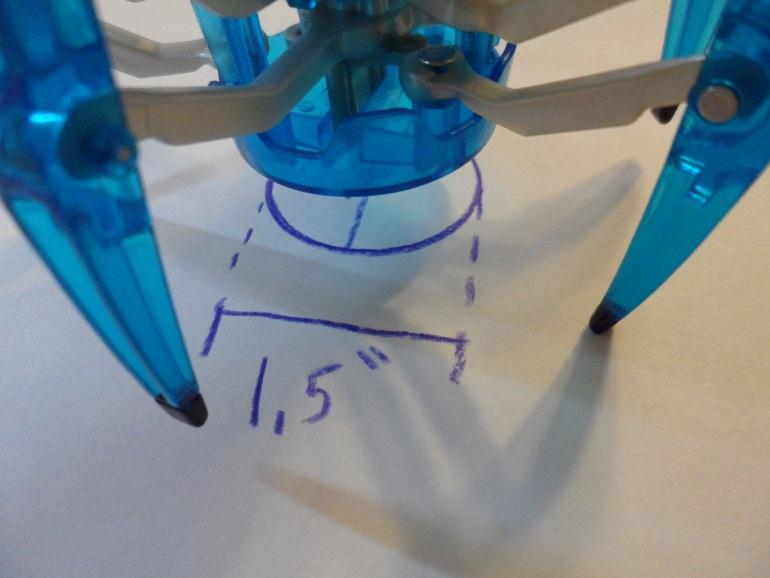
15 To insert batteries slide open the AAA battery holder and insert the batteries as shown in the diagram embossed in the plastic battery holder. Aiming the IR range sensor This is the most difficult part of building the robot. The IR range sensor has two parts. The clear device is called transmitter, the dark device is called a receiver. The transmitter and receiver have long leads that allow the devices at the end of the leads to be "aimed". Be sure the power switch on the battery holder is OFF. Using a pair of long-nose pliers, bend the leads to the clear device and the dark device aim at the same point. You can create a template to assist in aiming, by drawing a 1.5" diameter circle on a white piece of paper. 2.5" from the EDGE of the circle draw a small circle (dot) about 0.25 inches in diameter and fill it in. Place the robot centered on top of the 2.5" circle. Rotate the robot until the dot is between the transmitter and receiver. While looking down the transmitter, aim it at the dot. While looking down the receiver, aim it at the dot. Be sure none of the transmitter or receiver leads touch each other. This will create a short circuit and damage the board. Before turning on the robot, double check that none of the leads going to the transmitter or receiver are touching each other. Your first attempt at aiming the transmitter and receiver may not work. Aiming is not an exact science and will require some tweaking to get it perfect.


16


 approximately 180 degrees.")

17 Testing the Robot The EMGRobotics Hexbug Spider No Solder Hacking Kit comes pre-programmed for line following operation. The robot will follow a dark line on a bright surface, for example a black line on a white piece of paper. I use a piece of black electrical tape on my kitchen table. A thick black marker applied to a piece of cardboard will work as well. The line should be at least 0.5 inches wide. Place the robot on top of the black line with the sensors offset to the side of the line as shown in step 1 below. Be sure none of the transmitter or receiver leads touch each other. This will create a short circuit and damage the board. Slide the power switch on the battery holder to "ON". If the "top" and "bottom" motors have been connected to the board correctly, the robot should turn its head counter-clockwise (viewing from top) approximately 180 degrees. It will then turn clockwise until it "sees" the black tape. Finally it will start walking forward following the tape. In the images below the power switch is off, but that is only because I had to freeze the robot to take a picture. For this test, the power switch must be on. Step 1 Place robot as shown, slide switch to "ON". Step 2 Robot rotates CCW 180 deg. to detect line. Step 3 Robot rotates CW to find line. Step 4 Robot walks forward following line. If the robot does not find the line (step 3) and rotates Clock-Wise over the line, the transmitter and receiver may not be aimed correctly. Go back to "Aiming the IR range sensor".

18 Using your Newly Hacked Robot Using your robot is easy. Simply put the robot over the line, oriented as shown in step 1 above. Then slide the switch to the on position. The robot will rotate CCW 180 degrees as shown in step 2. While the robot is rotating, it is using the IR range sensor to measure the distance to the surface. The black tape absorbs the IR energy, making it look like it is far away. The robot basically "sees" the black tape as a gully. The robot records the "depth" of the gully and the "depth" of the surface on either side of the gully. After the robot has measures the "depth" of the gully and the surface around it, the robot uses the information to find the black tape. As shown in step 3, the robot rotates clock-wise until it finds the center of the gully. After finding the center of the gully, the robot will start walking forward as shown in step 4. For Advanced Users You can order the TI Launchpad for $4.30 from: The TI Launchpad is used to program the EMGRobotics MSP430G2553 Robot Controller used in the spider hack kit. The Launchpad connects to the robot controller using 3 wires, and can fully debug and program the robot controller. The TI Launchpad comes with the FREE Code Composer Studio professional C compiler and debugger. Using these tools you can create your program, flash it to the robot controller, and debug your program using breakpoints and stepping as expected from a professional tool. Time spent learning how to use the TI Launchpad and Code Composer Studio can be referenced on your resume. These are professional tools used by electronic manufactures around the world. The source code for the EMGRobotics Hexbug Spider No Solder Hacking Kit is available here:

19 The TI Launchpad plugs into the GND, TST, and RST pins on the EMGRobotics board (debug jumper wires not included). To disable the motors while debugging, remove the indicated jumper. Remove this jumper to disable motors while debugging. RST GND TST
20 EMGRobotics board shipped with No Solder Spider Hack Kit (MSP430G2553RCBLB) MSP430G2553 Function User Connector Description PIN PIN 1 VCC Connected to 3.0V regulator 2 NC 3 RXD/A1 8 UART RXD / IR Range Sensor 2 (RX) 4 TXD/A2 9 UART TXD / IR Range Sensor 3 (RX) 5 A3 USER 2 (IR Transistor) 6 NC 7 P1.5/TA0.0 LB1836M IN2 8 P2.0/TA1.0 LB1836M IN4 9 P2.1/TA1.1 LB1836M IN3 10 GPIO 11 GPIO 10 GPIO / IR Range Sensor 3 (TX) 12 GPIO IR LED 13 NC 14 I2C/A6 7 GPIO / IR Range Sensor 4 (RX) 15 I2C/A7/GPIO 6 GPIO / IR Range Sensor 4 (TX) 16 DEBUG-RST 5 Debug RST 17 DEBUG-TST 4 Debug TST 18 GPIO 3 GPIO / IR Range Sensor 2 (TX) 19 P2.6/TA0.1 LB1836M IN1 20 GND Motor Control Truth Table (IN1=P2.6, IN2=P1.5, IN3=P2.1, IN4=P2.0)
21 Software Personalities Robot Application (main.c) Board Files (boardrcblb.c/boardrcblb.h) Chip Files (EMGRobotics_MSP430G2553.c/EMGRobotics_MSP430G2553.h) The software has been designed to make it simple to modify the behavior of the robot. The robots personality is all coded in main.c. The example code uses a state machine to support four personalities. Changing personalities requires rebuilding the code and re-flashing the board. ROBOT_MODE MODE_TEST MODE_LINE_FOLLOWER MODE_AVOID_OBSTRUCTIONS MODE_ATTACKER Description Special test mode for manufacture testing Follow a black line Roam around avoiding obstructions Roam around, avoid obstructions, attack other robots when found You can change the robots personality by simply changing line 88 in main.c with the constant defined in the table above. main.c line 88 Robot_Mode = MODE_LINE_FOLLOWER; Software Architecture Robot Application (main.c) Board Files (boardrcblb.c/boardrcblb.h) Chip Files (EMGRobotics_MSP430G2553.c/EMGRobotics_MSP430G2553.h) Expanding the functionality of the robot beyond the limitations of the example code is easy using the functions available in the board and chip files. If you program the robot to do something cool, I encourage you to video your robot in action and post it on YouTube. I also encourage you to share your code on

22 Resources You can purchase the EMGRobotics Hexbug Spider No Solder Hacking Kit here: The source code for the EMGRobotics Hexbug Spider No Solder Hacking Kit is available here:
Repairing Microsoft Wedge Touch Mouse Battery Cover Retaining Clip
 Repairing Microsoft Wedge Touch Mouse Battery Cover Retaining Clip Disassembly, repair and reassembly of Wedge Touch mouse when the battery cover will not stay closed. Also is a good guide to repair other
Harmony Remote Repair
 Harmony Remote Repair harmonyremoterepair.com How to install your new Harmony One Front Cover/Touch Screen Important! Before you begin working on your Harmony One, you must discharge any static electricity
How to Build the Robotics++ V2 Robot. Last Edited Nov
 How to Build the Robotics++ V2 Robot Last Edited Nov. 15-2014 www.roboticscity.com 1 Completed Robotics++ V2 Robot. More views of completed robot can be found at the end of this instructions manual The
QUALITY MANAGEMENT SYSTEM
 Not controlled in hard copy Rev. 1.0 Date: Page 1 of 18 Subject The following instructions provide a step-by-step procedure to replace the heating element for DEF/SCR/UREA/ADBLUE/DIESEL After Treatment
OpenROV. Guide 3 - Electronics. We will now move to the assembly of the electronics that will control the ROV. Written By: OpenROV
 OpenROV Guide 3 - Electronics We will now move to the assembly of the electronics that will control the ROV. Written By: OpenROV 2017 openrov.dozuki.com Page 1 of 33 INTRODUCTION We will introduce soldering
Black and Decker CD2500 Motor Replacement
 Black and Decker CD2500 Motor Replacement The guide shows you how to replace the motor in a Black and Decker CD2500. Written By: Ashley ifixit CC BY-NC-SA www.ifixit.com Page 1 of 9 INTRODUCTION Make sure
Never power this piano with anything other than a standard 9V battery!
 Welcome to the exciting world of Digital Electronics! Who is this kit intended for? This kit is intended for anyone from ages 13 and above and assumes no previous knowledge in the field of hobby electronics.
Figure 1. CheapBot Line Follower
 The CheapBot Line Follower v2.0 is a plug-in single-board sensor for almost any programmable robot brain. With it, a robot can detect the presence of a black or white zone beneath its two sensors. In its
The Useless Machine. DIY Soldering Edition. Instruction Guide v0004
 The Useless Machine DIY Soldering Edition Instruction Guide v0004 TM For the best outcome, follow each step in order. We recommend reading this guide entirely before you get started. Tools required: Soldering
AAG CloudWatcher Update Humidity sensor (*)
") AAG CloudWatcher Update Humidity sensor (*) (*) For AAG CloudWatcher units SN 400 onwards. For a better understanding of these instructions we have divided them into two sections: to units with serial
AAG CloudWatcher Update Humidity sensor (*) (*) For AAG CloudWatcher units SN 400 onwards. For a better understanding of these instructions we have divided them into two sections: to units with serial
4. Z-axis assembly. 4. Z-axis assembly. Written By: Josef Prusa manual.prusa3d.com Page 1 of 18
 4. Z-axis assembly Written By: Josef Prusa 2017 manual.prusa3d.com Page 1 of 18 Step 1 Get the necessary tools 13/17mm spanners 3.6mm flathead screwdriver Needle-nose pliers 2.5 and 1.5mm Allen key Step
Installing Your Electronic Deadbolt
 Ultra Security Plus Electronic Deadbolt Installation Instructions http://www.hberger.com/video-gallery/electronic-deadbolt New Installation Lock Location Preparation (Skip this section if you door has
Telecaster Wiring Kits Please Read All Instructions Before Beginning. Tools you will need: Soldering tips: Removing Current Wiring: Step 1. Step 2.
 Telecaster Wiring Kits Please Read All Instructions Before Beginning. Tools you will need: Soldering Iron (35 watt preferably) Solder Wet Sponge Wire Clippers Wire Strippers 3/8 Drill Bit 5/32 Drill Bit
Connecting a Warp Feed to an Intelliframe
 Connecting a Warp Feed to an Intelliframe So you want to trigger your Warp Feed every time you pull the trigger? Sounds like a great idea! This step by step picture story will guide you through this process.
TOYOTA COROLLA EC REARVIEW MIRROR Section I Installation Preparation
 Section I Installation Preparation Part Number: PT374-02030 Section I Installation Preparation Kit Contents Item # Quantity Reqd. Description 1 1 AD Mirror Assembly w/compass & Maplights 2 1 Hardware Bag
Installation tutorial for Console Customs PS3 TrueFire Standard Rapid fire Microchip for Sixaxis and Dualshock 3 controllers
 Installation tutorial for Console Customs PS3 TrueFire Standard Rapid fire Microchip for Sixaxis and Dualshock 3 controllers This tutorial is designed to aid you in installation of a console customs rapid
Warning: CHOKING HAZARD -Small Parts. Not for Children Under 9 yrs. Kit Recommended for Ages 12 and up.
 The Original Warning: CHOKING HAZARD -Small Parts. Not for Children Under 9 yrs. Kit Recommended for Ages 12 and up. Table of Contents Soldering.. 3 How the WASP Works.. 7 The Build...... 12 Troubleshooting......30
WARNING: Prior to installation, turn the power off to the vending machine and unplug it from its power source. Also, make sure to level the machine.
 Installation of Gum and Mint Tray for National 147, 157, 167 Important Note: Please read all instructions thoroughly before continuing with installation of kit. If you are having problems installing the
LP-200 Dummy Load / Wattmeter
 LP-200 Dummy Load / Wattmeter Enclosure Retrofit Assembly Instructions March 2009 TelePost Incorporated LP-200 is a trademark of TelePost Inc. Material in this document copyrighted 2009 TelePost Inc. 1
IR add-on module circuit board assembly - Jeffrey La Favre January 27, 2015
 IR add-on module circuit board assembly - Jeffrey La Favre January 27, 2015 1 2 For the main circuits of the line following robot you soldered electronic components on a printed circuit board (PCB). The
meped v2 Assembly Manual
 meped v Assembly Manual The meped is an open source quadruped robot designed by Scott Pierce of Spierce Technologies, LLC. This design is released under the Creative Commons, By Attribution, Share Alike
STEP 1 : DESTROYER FRONT BUMPER INSTALL GATHER YOUR TOOLS AND LAY OUT YOUR PARTS... *shorty bumper to show hardware* Tools Required:
 DESTROYER FRONT BUMPER INSTALL JL STEP 1 : GATHER YOUR TOOLS AND LAY OUT YOUR PARTS... Tools Required: - Utility knife - 11/16 Deep socket - Ratchet - 11/16 Crescent wrench - Ratchet Extension - 1/4 socket
BUILD YOUR OWN. Pack 12
 BUILD YOUR OWN TM Pack 12 177 CONTENTS Assembly Guide 179 Stage 38: The right crankcase half Stage 39: The IR sensor board Stage 40: The left crankcase half Editorial and design by Continuo Creative, 39-41
Asus ZenFone 2 Display Replacement
 Asus ZenFone 2 Display Replacement Replace your display if it isn't functioning correctly or if it is cracked or broken. Written By: Jessica Nguyen ifixit CC BY-NC-SA www.ifixit.com Page 1 of 14 INTRODUCTION
Frivolous Engineering Useless Machine Soldering Instructions
 Frivolous Engineering Useless Machine Soldering Instructions The electronics assembly for the Useless Machine is very easy to solder together. It consists of 11 parts as shown in the photo. Required tools
DIODE / TRANSISTOR TESTER KIT
 DIODE / TRANSISTOR TESTER KIT MODEL DT-100K Assembly and Instruction Manual Elenco Electronics, Inc. Copyright 1988 Elenco Electronics, Inc. Revised 2002 REV-K 753110 DT-100 PARTS LIST If you are a student,
Open Air. Kit includes: Drawer Full Indicator board assembly, (2) retainers, and (4) screws. PREPARATION
 retainers, and (4) screws. PREPARATION") Open Air Installation Video You will need: 8-inch #2 Phillips screwdriver Needle-nose pliers DFI INSTALLATION GUIDE For installation videos, visit the Customer Service playlist at www.youtube.com/user/thelitterrobot
Open Air Installation Video You will need: 8-inch #2 Phillips screwdriver Needle-nose pliers DFI INSTALLATION GUIDE For installation videos, visit the Customer Service playlist at www.youtube.com/user/thelitterrobot
Installing the 3 Indexer: PRS Standard Tools
 888-680-4466 ShopBotTools.com Installing the 3 Indexer: PRS Standard Tools Copyright 2016 ShopBot Tools, Inc. page 1 Copyright 2016 ShopBot Tools, Inc. page 2 Table of Contents Route Cable into Box...5
Mini Cooper Lock Actuator
 2001-2006 Mini Cooper Lock Actuator Replacement This guide is on how to remove the lock actuator from the cars door. Written By: Jem ifixit CC BY-NC-SA www.ifixit.com Page 1 of 13 INTRODUCTION In order
The Useless Machine. Parts Only - Build Guide v0001
 TM The Useless Machine Parts Only - Build Guide v0001 For the best outcome, follow each step in order. We recommend reading this guide entirely before you get started. Tools required: One phillips screwdriver,
Line-Following Robot
 1 Line-Following Robot Printed Circuit Board Assembly Jeffrey La Favre October 5, 2014 After you have learned to solder, you are ready to start the assembly of your robot. The assembly will be divided
tinycylon Assembly Instructions Contents Written by Dale Wheat Version August 2016 Visit dalewheat.com for the latest update!
 tinycylon Assembly Instructions Written by Dale Wheat Version 2.1 10 August 2016 Visit dalewheat.com for the latest update! Contents Assembly Instructions...1 Contents...1 Introduction...2 Quick Start
FM Wireless Microphone Kit Instructions for Assembly Page 1 of 5
 Instructions for Assembly Page 1 of 5 1. Find Resistor R1. Remove any tape that may be attached to the leads. Bend the leads as needed to insert Resistor R1 into the printed circuit board in the holes
1. ASSEMBLING THE PCB 2. FLASH THE ZIP LEDs 3. BUILDING THE WHEELS
 V1.0 :MOVE The Kitronik :MOVE mini for the BBC micro:bit provides an introduction to robotics. The :MOVE mini is a 2 wheeled robot, suitable for both remote control and autonomous operation. A range of
SMARTfit Functional and Brain Fitness Training Multi-Station Trainer Installation for Stud and Concrete Walls (US)
") SMARTfit Functional and Brain Fitness Training Multi-Station Trainer Installation for Stud and Concrete Walls (US) 2017 SMARTfit, Inc. www.smartfitinc.com 1 Unlike other fitness equipment which may require
SMARTfit Functional and Brain Fitness Training Multi-Station Trainer Installation for Stud and Concrete Walls (US) 2017 SMARTfit, Inc. www.smartfitinc.com 1 Unlike other fitness equipment which may require
Line Following Circuit Board Wiring Guide
 Line Following Circuit Board Wiring Guide Soldering the Analog Optosensors 1. Obtain a line following printed circuit board from the store as well as three analog optosensors (w/6 resistors). 2. Remove
DC Motor. Controller. User Guide V0210
 DC Motor Controller User Guide 59757 V0210 This kit provides a great exercise of intermediate soldering skills and creates a device that enables you to control various Pitsco motors, Tamiya gearboxes,
Spiderbeam Balun Construction Guide
 BALUN CONSTRUCTION GUIDE Ver. 1.0 1 The components of the Balun Kit are in a plastic bag. Most of the components are inside the plastic case of the balun. The aluminum U-profile and the RG-142 Teflon Coax
Catch The Bug. Body Build. Where are we? Process # You are. here.
 Catch The Bug Body Build Process # 1 Where are we? 1) Body Build- The mechanical part of the bug is constructed. 2) Electronics Lab- Bug Experiments teach the fundementals of electronics. 3) Final Wiring-
Razr Adapter Retrofit Project by Craig Hoy, Edmonton, AB, Canada
 Razr Adapter Retrofit Project by Craig Hoy, Edmonton, AB, Canada The following is a description of the process that I have used to modify the console eject box for e38, e39, e46 and x5 s, part number 84-21-6-933-415.
ELECTRIC RACER BASIC BUILD
 Page 1 Name: Set: Date: This guide will take you through the process of creating a basic electric racer. After you finish this build, you should be able to experiment, design and engineer your own racer.
Digital Electronics & Chip Design
 Digital Electronics & Chip Design Lab Manual I: The Utility Board 1999 David Harris The objective of this lab is to assemble your utility board. This board, containing LED displays, switches, and a clock,
GORE Aerospace Ethernet Cables
 Termination Instructions The following procedures are based on Gore s best practices for terminating GORE Aerospace with the Carlisle Octax Connector System for both socket and plug versions. These procedures
Standard Kit #1 (3-way switch)
") Standard Kit #1 (3-way switch) Please Read All Instructions Before Beginning. Tools you will need: Soldering Iron (35 watt preferably) Solder Wet Sponge Wire Clippers 3/8 Drill Bit 1/4 Drill Bit Variable
Standard Kit #1 (3-way switch) Please Read All Instructions Before Beginning. Tools you will need: Soldering Iron (35 watt preferably) Solder Wet Sponge Wire Clippers 3/8 Drill Bit 1/4 Drill Bit Variable
FACTORY CAT TOMCAT CORPORATION
 FACTORY CAT RPS TOMCAT CORPORATION Artificial Turf and Carpet Sweeping Install Kit #349-641 & #349-642 1. Detach batteries so that there is no power running through the machine before starting. 2. Start
Tools Required: - Utility knife - 11/16 Deep socket - Ratchet - 11/16 Crescent wrench - Ratchet Extension - 1/4 socket - Electrical tape
 DESTROYER FRONT BUMPER INSTALL JL STEP 1 : GATHER YOUR TOOLS AND LAY OUT YOUR PARTS... Tools Required: - Utility knife - 11/16 Deep socket - Ratchet - 11/16 Crescent wrench - Ratchet Extension - 1/4 socket
Section 5 BATTERY REPLACEMENT
 u Section 5 BATTERY REPLACEMENT j i 5.1 General The internal battery is used for preserving the clock and programming memory in the models 5000 and 7000. I i The procedure for each is given separately.
DP-19 DUAL PURPOSE DETECTOR INSTRUCTION MANUAL
 DP-19 DUAL PURPOSE DETECTOR INSTRUCTION MANUAL Case Size: 5.3 h X 3.3 w x 1.5 d@ Weight: 8 oz. ABOUT THE DP-19 Battery: 9 volt transistor type Eveready 216 or equal Current: 17 milliamps Frequency Response:
Installation Guide. Cue Front Unit (Code and Key) Cue Front Unit (RFID) Cue Rear Unit (Latch and Bolt)
 Cue Front Unit (RFID) Cue Rear Unit (Latch and Bolt)") Installation Guide Cue Front Unit (Code and Key) Cue Front Unit (RFID) Cue Rear Unit (Latch and Bolt) Table of Contents Before Lock Installation3 Surface Mount Installation For door thickness measuring
Installation Guide Cue Front Unit (Code and Key) Cue Front Unit (RFID) Cue Rear Unit (Latch and Bolt) Table of Contents Before Lock Installation3 Surface Mount Installation For door thickness measuring
66 Dodge Charger (and others) Tach board
 Tach board") 66 Dodge Charger (and others) Tach board Introduction: This board replaces the original tachometer driver board in the 66 charger and other cars that use electronics external to the tachometer. The board
66 Dodge Charger (and others) Tach board Introduction: This board replaces the original tachometer driver board in the 66 charger and other cars that use electronics external to the tachometer. The board
Z-Truck Up-and-Down Motion. Y-Truck Side-to-Side Motion. Head. Squaring Plate. Sliding Plate FIGURE 1: THE CARVEWRIGHT MACHINE
 Setup and use of CarveWright CO2 Powered Dragster Jig The CO 2 powered Dragster Jig will arrive from the factory fully assembled, calibrated, and squared. In order to get the best results, your CarveWright
1.9 KIT # Fits Aerotech 1.9 diameter rockets. Uses coupler and payload tube included with select Aerotech Kits. Ebay Parts List Description.
 KIT #0545.9 Fits Aerotech.9 diameter rockets. Uses coupler and payload tube included with select Aerotech Kits. Ebay Parts List P/N Description Qty 5405.9 Ebay Laser Cut Sheet Thin 5406.9 Ebay Laser Cut
Assembly Instructions: Kit #5
 Assembly Instructions: Kit #5 1. Insert the T-pin into one of the caps. 2. Insert the rotor core into the same cap as shown below. Apply some pressure to push the rotor core approximately 1/2" (10-12 mm)
Instructions to Convert a 4-foot Florescent Fixture to LEDs Using 60W Power Supply Using 2 or 3 strips 30Dec15
 Instructions to Convert a 4-foot Florescent Fixture to LEDs Using 60W Power Supply Using 2 or 3 strips 30Dec15 Thank you for purchasing the Shoplight Solutions 4-ft conversion kit. This is a companion
KN-8828B Upgrade Directions
 KN-8828B Upgrade Directions This document outlines the steps to take to update earlier Hottop Bean Roasters to the KN-8828B 2007 by Chang Yue and Hottop USA - All Rights Reserved No part of this document
Experimental Procedure
 1 of 17 9/11/2018, 1:24 PM https://www.sciencebuddies.org/science-fair-projects/project-ideas/robotics_p012/robotics/build-a-light-tracking-bristlebot (http://www.sciencebuddies.org/science-fairprojects/project-ideas/robotics_p012/robotics/build-a-light-tracking-bristlebot)
Total solder points: 66 Difficulty level: beginner advanced. 15 Channel IR remote stick K8051 ILLUSTRATED ASSEMBLY MANUAL
 Total solder points: 66 Difficulty level: beginner 1 2 3 4 5 advanced 15 Channel IR remote stick K8051 Sleek designer enclosure with just 2 buttons, yet it provides acces to a stunning 15 channels. ILLUSTRATED
Installation tutorial for Console Customs Xbox 360 Dual Rapid fire Microchip for wired and wireless controllers (all versions)
") Installation tutorial for Console Customs Xbox 360 Dual Rapid fire Microchip for wired and wireless controllers (all versions) This tutorial is designed to aid you in installation of a console customs
Installation tutorial for Console Customs Xbox 360 Dual Rapid fire Microchip for wired and wireless controllers (all versions) This tutorial is designed to aid you in installation of a console customs
Instructions to Convert a 4-foot Florescent Fixture to LEDs Using a SS 25W Power Supply and a 4 LED strip 30Dec15
 Instructions to Convert a 4-foot Florescent Fixture to LEDs Using a SS 25W Power Supply and a 4 LED strip 30Dec15 Thank you for purchasing the Shoplight Solutions 4-ft conversion kit. This is a companion
Tek-Bot Remote Control Transmitter Board Construction
 Tek-Bot Remote Control Transmitter Board Construction Purpose This tutorial illustrates the procedure for construction of the Transmitter board for the Tek-bot. A Guide to Soldering Many of you have soldered
Selfsat TOP. Satellite Flat Antenna with Lift and Rotation Unit. Manual
 Selfsat TOP Satellite Flat Antenna with Lift and Rotation Unit Manual 1. Contents: www.camos-multimedia.com Quantity Description 1 Antenna Selfsat HD 10 1 Lift and Rotation Unit (pre-assembled) 2 Ceiling
Explorer Wiring Kit (assembled)
") Explorer Wiring Kit (assembled) For Vintage, Firestorm & Standard Series Please Read All Instructions Before Beginning. Tools you will need: Soldering Iron (35 watt preferably) Solder Wet Sponge Wire Clippers
Explorer Wiring Kit (assembled) For Vintage, Firestorm & Standard Series Please Read All Instructions Before Beginning. Tools you will need: Soldering Iron (35 watt preferably) Solder Wet Sponge Wire Clippers
ENGR 40M Project 2a: Useless box
 ENGR 40M Project 2a: Useless box Prelab due 24 hours before your section, April 16 19, 2018 Lab due before your section, April 24 27, 2018 1 Objectives In this lab, you ll assemble a useless box like the
SMARTfit High Intensity Cognitive Training. SMARTfit Trainer Installation Manual for Stud and Concrete Walls Revision 1.3
 SMARTfit High Intensity Cognitive Training SMARTfit Trainer Installation Manual for Stud and Concrete Walls Revision 1.3 2015 Unlike other fitness equipment which may require additional insurance, SMARTfit
Understanding the Controls
 Understanding the Controls Your new Millennium or Freedom SR machine uses simple controls and has handy features to make your quilting more fun and enjoyable. The charts below give you a quick overview
Ribcage Installation. Part 2 - Assembly. Back-Bone V1.06
 Ribcage Installation Part 2 - Assembly Back-Bone V1.06 Contents Section 1 Before You Get Started... 2 Included With Your Kit:... 2 Figure: A... 3 CAUTION!... 4 Note:... 4 Tools Required... 5 Section 2:
Geiger Counter Kit Assembly Instructions ( )
") Geiger Counter Kit Assembly Instructions (2012-05-11) To build this kit, you should know how to solder. And it will be much easier if you have made other kits before. But even if this is your first kit,
Geiger Counter Kit Assembly Instructions (2012-05-11) To build this kit, you should know how to solder. And it will be much easier if you have made other kits before. But even if this is your first kit,
The Walford Electronics Ford Receiver Kit Project Construction Manual
 The Walford Electronics Ford Receiver Kit Project Construction Manual Walford Electronics Ford Receiver construction manual V1.5 Page 1 of 22 Introduction The Ford receiver has four stages: The first stage
KN-Q10 Assembly Manual
 KN-Q10 Assembly Manual Translated by Adam Rong, BD6CR/4 with permission from Ke Shi, BA6BF Edited by Stephen, VK2RH Revision B, Oct 14, 2010 Thank you for purchasing the KN-Q10 4 Band SSB/CW Dual Mode
Assembly Instructions for the 1.5 Watt Amplifier Kit
 Assembly Instructions for the 1.5 Watt Amplifier Kit 1.) All of the small parts are attached to a sheet of paper indicating both their value and id. 2.) Leave the parts affixed to the paper until you are
Sentinel Series Cigar Humidor End Tables
 Sentinel Series Cigar Humidor End Tables Assembly Instructions Models: Sentinel 500, 1000 and 1500 Style: Contemporary SENTINEL ASSEMBLY INSTRUCTIONS Congratulations! You have purchased a superior cigar
1 Day Robot Building (MC40A + Aluminum Base) for Edubot 2.0
 for Edubot 2.0") 1 Day Robot Building (MC40A + Aluminum Base) for Edubot 2.0 Have you ever thought of making a mobile robot in 1 day? Now you have the chance with MC40A Mini Mobile Robot Controller + some accessories.
1 Day Robot Building (MC40A + Aluminum Base) for Edubot 2.0 Have you ever thought of making a mobile robot in 1 day? Now you have the chance with MC40A Mini Mobile Robot Controller + some accessories.
Removing and Replacing the Y-truck
 Service Documentation Removing and Replacing the Y-truck To remove and replace the Y-truck you will need the following tools: 4mm Allen wrench 12mm stamped flat wrench #2 Phillips screwdriver (magnetic
Instructions to Convert a 4-foot Florescent Fixture to LEDs Using 100W Power Supply Using 1-4 strips 30Dec15
 Instructions to Convert a 4-foot Florescent Fixture to LEDs Using 100W Power Supply Using 1-4 strips 30Dec15 Thank you for purchasing the Shoplight Solutions 100W conversion kit. This is a companion document
JD-12. Instruction & Parts Manual
 JD-12 Instruction & Parts Manual Framon Manufacturing Company, Inc. 909 W Washington Avenue Alpena, MI 49707 Phone: 989-354-5623 Fax: 989-354-4238 E-mail: support@framon.com Website: www.framon.com The
Patton Robotics ESRA II Expressive System for Robotic Animation
 Patton Robotics ESRA II Expressive System for Robotic Animation Assembly and Operation Instructions Version 1.0 Patton Robotics, LLC. 61 Hagan Drive New Hope, PA 18938 Copyright 2015 Patton Robotics, LLC.
Installation Instruction
 Installation Step 1 Cut Upper Guide and Lower Tracks to opening size Step 2 Mount Upper Track to soffit or ceiling. Use appropriate mounting hardware for your field conditions. NOTE: The Lower Track is
Custom Pendant- Hardwire Assembly and Installation Instructions
 Custom Pendant- Hardwire Assembly and Installation Instructions CAUTION: BEFORE INSTALLING FIXTURE, MAKE SURE THE POWER TO THE CIRCUIT IS TURNED OFF AT THE MAIN FUSE BOX / CIRCUIT BREAKER UTILITY BOX.
The SCB-68 is a shielded board with 68 screw terminals for easy connection to National Instruments 68-pin products.
 NATIONAL INSTRUMENTS The Software is the Instrument SCB-68 68-Pin Shielded Connector Block Installation Guide Part Number 320745-01 This guide describes how to connect and use the SCB-68 68-pin shielded
Sentinel Series Cigar Humidor End Tables
 Sentinel Series Cigar Humidor End Tables Assembly Instructions Models: Sentinel 500, 1000 and 1500 Style: Traditional SENTINEL ASSEMBLY INSTRUCTIONS Congratulations! You have purchased a superior cigar
Custom Front Panel Upgrade Instructions
 Custom Front Panel Upgrade Instructions Here are the directions for upgrading your SP-II to an SP-IIB, with a custom blackanodized front panel and engraved lettering. There are only forty SP-IIB s in existence
Adafruit Pi Box Plus. Created by Phillip Burgess. Last updated on :38:17 AM UTC
 Adafruit Pi Box Plus Created by Phillip Burgess Last updated on 2018-01-13 05:38:17 AM UTC Guide Contents Guide Contents Assembly Instructions Preparation Parts List Assembly Opening the Lid If Using a
TLE9879 EvalKit V1.2 Users Manual
 TLE9879 EvalKit V1.2 Users Manual Contents Abbreviations... 3 1 Concept... 4 2 Interconnects... 5 3 Test Points... 6 4 Jumper Settings... 7 5 Communication Interfaces... 8 5.1 LIN (via Banana jack and
DO NOT PULL ON THE SHEATH.
 Removing and Replacing the Head Cover To remove and replace the head cover you will need the following tools: #2 Phillips screwdriver (magnetic tip preferred) Removing the Head Cover 1. Ready the machine
Inde-Pendants Family. 32L Ring Plaster Trim, Grid and Drywall Ceiling Types. Document No Installation instructions for 32L-Rxx-P
 Inde-Pendants Family 32L Ring Plaster Trim, Grid and Drywall Ceiling Types Installation instructions for 32L-Rxx-P Document No. Supplied by Litecontrol 32L Inde-Pendants: Ring (Plaster Trim, Grid and Drywall
irobot Roomba 980 Motherboard Replacement
 You will be able to remove the device's motherboard and replace it in case it is damaged. Written By: Ernesto Rodriguez Romero ifixit CC BY-NC-SA www.ifixit.com Page 1 of 13 INTRODUCTION Replacing the
Repairing your Porsche 928 Central Warning System (CWS) controller
 controller") Repairing your Porsche 928 Central Warning System (CWS) controller Disclaimer: This procedure is for a 1984 Porsche 928 S controller. Overview: Under the left foot pedal (dead pedal) of the Porsche 928
Repairing your Porsche 928 Central Warning System (CWS) controller Disclaimer: This procedure is for a 1984 Porsche 928 S controller. Overview: Under the left foot pedal (dead pedal) of the Porsche 928
Figure 1. CheapBot Smart Proximity Detector
 The CheapBot Smart Proximity Detector is a plug-in single-board sensor for almost any programmable robotic brain. With it, robots can detect the presence of a wall extending across the robot s path or
The W3FF Portable Dipole
 The W3FF Portable Dipole This is the antenna I designed for my 'walking portable' station. It is a dipole constructed out of the plastic plumbing pipe CPVC. There are telescoping whips at the ends of each
GENUINE ACCESSORIES INSTALLATION INSTRUCTIONS. ITEM QTY DESCRIPTION Usage Chart
 PART NUMBER: 0000 8C R0 GENUINE ACCESSORIES INSTALLATION INSTRUCTIONS Rev. AAA *550-0554-000* APPLICABLE MODELS: 203 > CX-5 REQUIRED COMPONENTS: ITEM QTY DESCRIPTION Usage Chart MIRROR ASSEMBLY: Mirror
DIY Instructions For NGPC Front Light Installation using the Gameboy Advanced SP Front Light
 DIY Instructions For NGPC Front Light Installation using the Gameboy Advanced SP Front Light Tools you will need: Phillips Screwdriver Flat head Screwdriver Tri-wing Screwdriver Exacto Knife Soldering
Rapid LED NanoCube 28 CF Quad Retrofit
 1 Rapid LED NanoCube 28 CF Quad Retrofit Contents Foreword... 1 Outline... 2 Hood Preparation... 2 Attaching LEDs to Heatsink and Wiring LEDs Together... 6 Thermal Grease... 6 Soldering Notes... 7 Tinning
METAL BLINDS. Deluxe GETTING STARTED OPTIONAL HARDWARE. A few simple tools are required: STANDARD HARDWARE
 METAL BLINDS Deluxe GETTING STARTED OPTIONAL HARDWARE A few simple tools are required: Steel Tape Measure Pencil Level Hold Down Brackets with Screws Extension Bracket Power Drill and Drill Bits Flathead
Start by building the example racer, then turn it into your own unique design.
 Start by building the example racer, then turn it into your own unique design. For use with TeacherGeek Air Racer Activity Pack, or Maker Cart. To find documents and activity materials, click here. Page
ANATOMY OF A BIT TM how you can tell top from bottom. four on the floor!
 CRAWLY CREATURE BASICS 1 Learn BITSNAP ANATOMY OF A BIT TM how you can tell top from bottom. TOP BOTTOM BIT FEET 2 which COLOR-CODED BY FUNCTION Bits TM are grouped into four different categories, are
Secret Storage Book. Part Lists. The Book
 Secret Storage Book Part Lists Wood Screws ( (Werbilt flat head phillips #4 x ⅜ in) Drills Screwdrivers Hinges (2 medium and 3 small) Corner braces (¾ inches) Paint or scrapbook paper Leather Thick cardboard
FIELD REPLACEABLE UNIT DOCUMENTATION
 GENERAL INFORMATION Tools Required for Proper Disassembly and Reassembly: 1. Phillips Screwdriver (Size0&1) 2. 4mm Flat head Screwdriver 3. Case Separator 4. ESD Wrist Strap 5. ESD mats 6. Tweezers Before
* * APPLICABLE MODELS: 2014 > MAZDA 3
 PART NUMBER: 0000 8C L46 GENUINE ACCESSORIES INSTALLATION INSTRUCTIONS Rev. AAA *550-0604-000* APPLICABLE MODELS: 204 > MAZDA 3 REQUIRED COMPONENTS: ITEM QTY DESCRIPTION Usage Chart MIRROR ASSEMBLY: Mirror
01. Parts. Blink v1.1. Battery Holder x1. Red LED x1 Green LED x1 Blue LED x1. Resistors x3. Battery x1. Blink PCB x1. Push Button Switchers x3
 Blink L1 L2 L3 01. Parts Battery Holder x1 Red LED x1 Green LED x1 Blue LED x1 Resistors x3 Learn to Solder Kit Battery x1 L1 L2 L3 Blink PCB x1 S3 Push Button Switchers x3 02. Tools RECOMENDED Soldering
Pivot Frame Mounting Instructions
 A D E I J What Is In The Box B C F * Some Pivot Frames include Extra Spring Clips for Mat if spring clips are lost or to flatten mat in frame. G H Description QTY A. Pivot Frame 1 B. Upper Catch Bracket