D. W.Knight 1981, 1987, 2013, 2015.
|
|
|
- Horace Hawkins
- 5 years ago
- Views:
Transcription
1 -i supplement Model 950AF Ultrasonic Receiver with Audio Filter Models T800 mk II, T900X and T900V Ultrasonic Transmitters Design and Pre-production Development D W Knight BSc, PhD, Oct 1987 b With corrections and additions Version 201, 15th March 2015 D W Knight 1981, 1987, 2013, 2015
2 - ii - Contents Page 1 1 Introduction Circuit Description Variable feedback gain control system Input attenuators Tuning circuitry and intermediate amplification Linear RMS sensing voltmeter and detector AF Output stage Model 950 electronic supply switching Adjustment and Implementation of Options Functions of the unit Input attenuators HF gain control law Choice of HF bandwidth Tuning adjustment Intermediate gain and sensitivity adjustment Signal to noise ratio Scale expansion AF bandwidth Model R900 receiver Model R910 receiver Model R950 IS receiver Models R950AF, T800 mkii, T900X and T900V Introduction Note on nomenclature Model R950AF Bandpass filter Audio filter and VU meter R950AF production details Transmitter models T800 mkii, T900X and T900V Filter module components list Transmitter components list a1 a1 a2 a2 a4 a4 a9 a17 a18 Ultrasonic sensors SE05B-40T and SE05B-40R Headset and charging connector for R950 a19 a21 3 A A
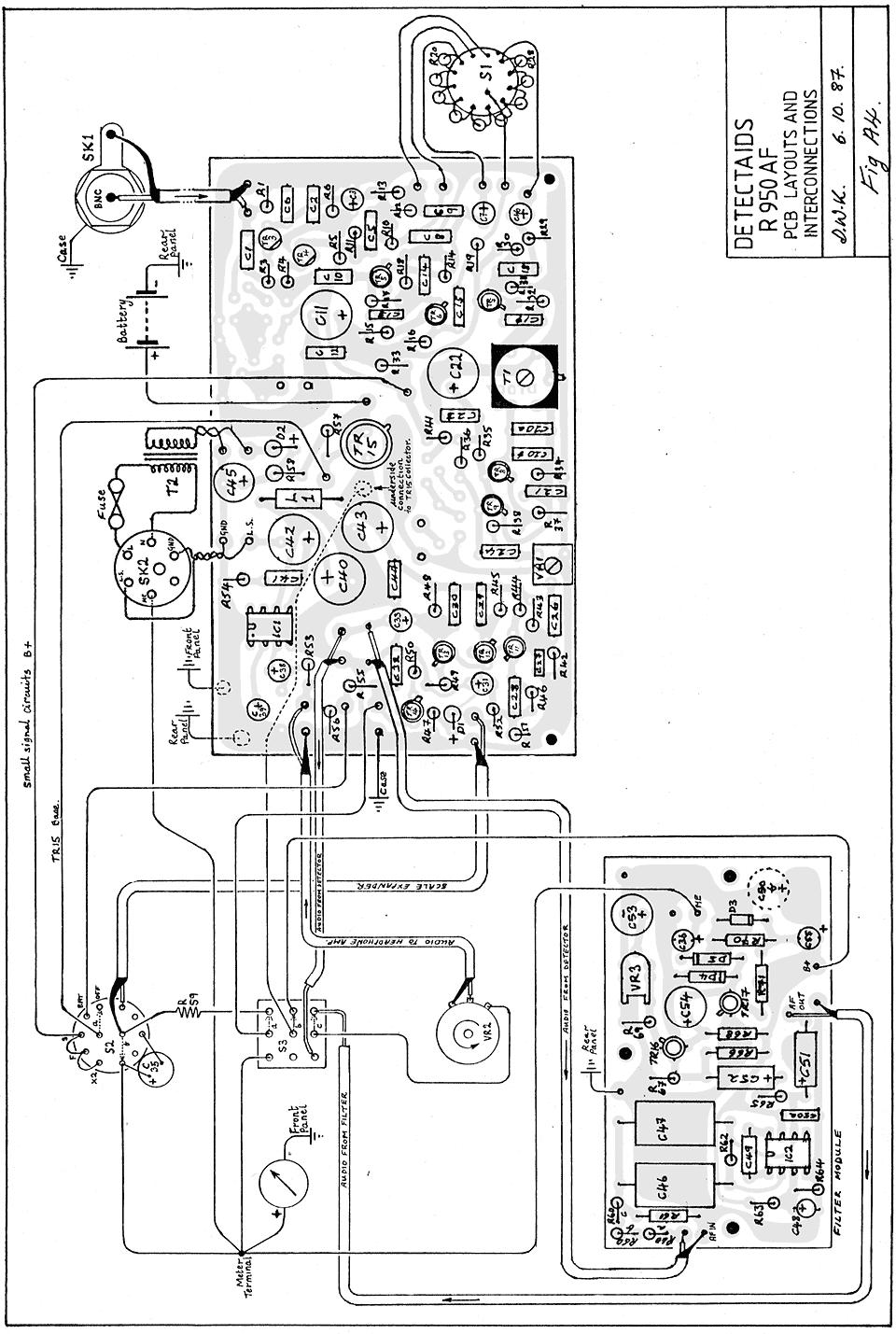
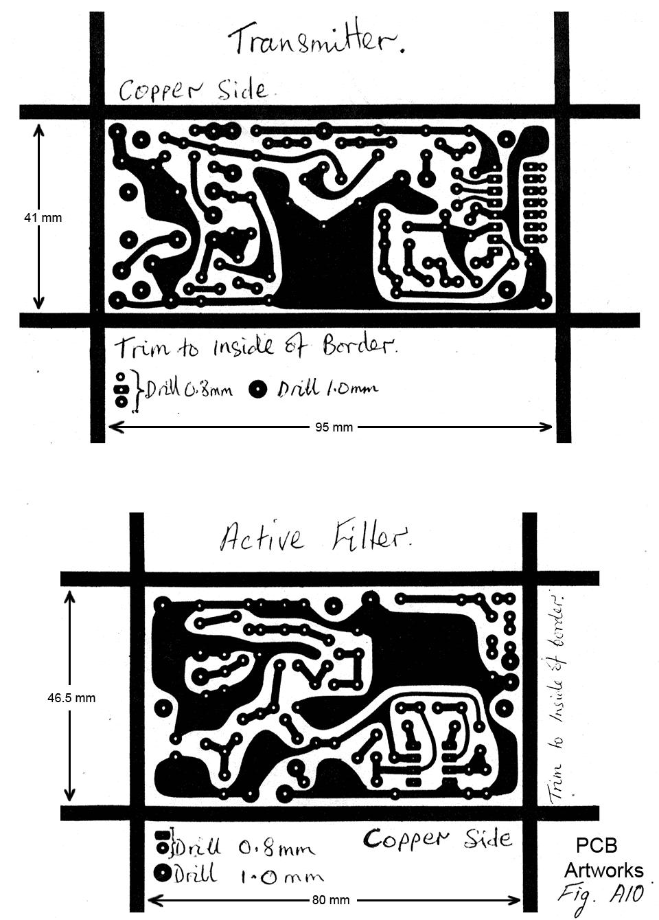
3 - iii - Diagrams Fig 1 Fig 2 Fig 3 Fig 4 Fig 5 Fig 6 Fig 7 Fig 8 Fig A1 Fig A2 Fig A3 Fig A4 Fig A5 Fig A6 Fig A7 Fig A8 Fig A9 Fig A10 Functional elements of the receiver 900 series prototype circuit Variable feedback gain control Broadband circuit Meter circuit Model 900 Model 910 Model 950 Filter design procedure Filter and VU meter circuit diagram R950AF complete circuit R950AF wiring T800 mkii circuit and PCB layout T900X circuit and PCB layout T900V circuit and PCB layout CMOS 4060 pinout CMOS 4060 internal logic and RC oscillator graph PCB artworks Note: Some diagrams need to be rotated through 90º for viewing on a computer screen In Adobe Acrobat: [Ctrl] [Shift] + rotates the display 90º clockwise [Ctrl] [Shift] rotates the display 90º anticlockwise Page a3 a5 a7 a8 a11 a12 a13 a14 a15 a16
4 -1-
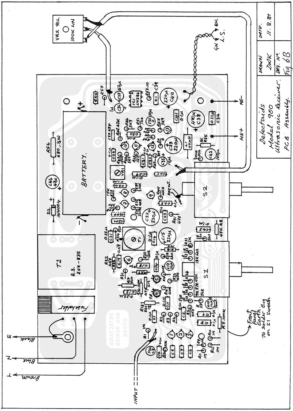
5 -2- The complete prototype circuit is given in fig 2 (next page) Note The half-wave rectifier used in the Ni-Cd battery charging circuitry (see fig 2) is a leftover from the earlier Detectaids 800-series The author's attempt to change it to a bridge was rejected on grounds of cost The use of half-wave rectification in conjunction with power transformers is not recommended
6 Fig 2: 900 Series prototype circuit
7 -3-
8 -4-
9 -5-
10 -6-
11 -7-
12 -822 Input attenuators
13 -9-
14 - 10 -
15 Linear high-frequency voltmeter and detector
16 - 12 Hence IL = VIN / RL When the circuit is driven by an AC signal, TR1 drives the load current positive and TR2 drives the load current negative Hence the average current flowing in TR2 collector is the mean half-wave rectified load current This can be found by integration1 and is given by: Im = ( 2) VIN (rms) / π RL The meter movement is not at signal potential, which means that it can be mounted close to the input socket or attenuator without jeopardising circuit stability Meter sensitivity is defined by the choice of RL, and the scale is highly linear Note that the meter could be placed in the collector of TR1 or TR2 By placing a resistor in the collector of TR1 and shunting it with a suitable smoothing capacitor, the circuit also behaves as a highly linear radio detector This output is used to provide the detected audio signal The product of this resistance and capacitance is the detector time constant, which sets the audio corner (-3 db) frequency according to the relationship: f-3db = 1 / 2πCR By choosing RL = 100 Ω and a meter movement of 100 μa FSD, the voltmeter has a sensitivity if 222 mv RMS FSD A 1 μv signal thus only requires 87 db of voltage amplification in order to give a full-scale reading By switching another resistor in parallel with RL, a scale-expansion facility can be provided This option is used in the model 950 By placing another 100 Ω resistor (R52) in parallel with R51, RL is reduced to 50 Ω and the circuit sensitivity increases to 111 mv RMS FSD The scale expansion obtained is thus 2 (+6 db) The 100 μa FSD meter can, if so desired, be calibrated in db The following table gives db points on a scale assuming + 3dB = 100% This can be used for constructing the meter-scale artwork db % FS The derivation is given in the article: A Linear high-frequency voltmeter and AM detector D W Knight
17 - 13 -
18 - 14 -
19 - 15 -
20 Note that the only reason for including these capacitors is to make the 900 series receivers sound like the old 800 series receiver, which had very poor audio quality
21 - 18 -
22 - 19 -
23
24 - 20 -
25
26
27 - 21 -
28 - 22 -
29 - 23 -
30 - 24 -
31 - 25 -
32
33
34 - 26 -
35 - a1 -
36 - a2 -
37 - a3 -
38 - a4 -
39 - a5 -
40 - a6 -
41 - a7 -
42 - a8 -
43 - a9 -
44 - a10 -
45 - a11 -
46 - a12 -
47 - a13 -
48 - a14 - Note: The CMOS 4060 counter has no outputs for divide by 2, 4, 8, and 2048
49 - a15 -
50 - a16 -
51 - a17 -
52 - a18 -
53 - a19 -
54 - a20 -
55 - a21 -
RADIO AMATEUR EXAM GENERAL CLASS
 RAE-Lessons by 4S7VJ 1 CHAPTER-7 RADIO AMATEUR EXAM GENERAL CLASS MEASURMENTS By 4S7VJ 7.1 TEST EQUIPMENT & MEASUREMENTS Correct operation of amateur radio equipment involves measurements to ensure optimum
TBA120 Series & SN FM Demodulator IC
 TBA120 Series & SN76660 - FM Demodulator IC The TBA120 Series ICs provide a high-gain limiting IF amplifier and a quadrature coincidence detector in one package. These ICs are primarily intended for extraction
Table of Contents...2. About the Tutorial...6. Audience...6. Prerequisites...6. Copyright & Disclaimer EMI INTRODUCTION Voltmeter...
 1 Table of Contents Table of Contents...2 About the Tutorial...6 Audience...6 Prerequisites...6 Copyright & Disclaimer...6 1. EMI INTRODUCTION... 7 Voltmeter...7 Ammeter...8 Ohmmeter...8 Multimeter...9
Automatic Tracking Filter for DDS Generator
 Riccardo Gionetti, IØFDH Via S. Bernadette, 00 Roma RM, Italy: rgionetti@virgilio.it Automatic Tracking Filter for DDS Generator Reduce spurious responses from a digital synthesizer with this filter. The
VTU NOTES QUESTION PAPERS NEWS RESULTS FORUMS TESTING OF HALF WAVE, FULL WAVE AND BRIDGE RECTIFIERS WITH AND WITHOUT CAPACITOR
 TESTING OF HALF WAVE, FULL WAVE AND BRIDGE RECTIFIERS WITH AND WITHOUT CAPACITOR Aim: To determine the ripple factor, efficiency and regulation of the half wave, full wave and bridge rectifier circuits
UNIT-3. Electronic Measurements & Instrumentation
 UNIT-3 1. Draw the Block Schematic of AF Wave analyzer and explain its principle and Working? ANS: The wave analyzer consists of a very narrow pass-band filter section which can Be tuned to a particular
LINEAR IC APPLICATIONS
 1 B.Tech III Year I Semester (R09) Regular & Supplementary Examinations December/January 2013/14 1 (a) Why is R e in an emitter-coupled differential amplifier replaced by a constant current source? (b)
AS Electronics Project: 3-Channel Sound-to-Light Display
 : 3-Channel Sound-to-Light Display By 1. Contents 1. CONTENTS...2 2. AIM...3 3. SPECIFICATION...3 4. POSSIBLE SOLUTIONS...4 4.1. FILTERS...4 4.2. RECTIFIERS...4 5. CHOSEN SOLUTION...5 5.1. BUFFER...5 5.2.
EXPERIMENT FREQUENCY RESPONSE OF AC CIRCUITS. Structure. 8.1 Introduction Objectives
 EXPERIMENT 8 FREQUENCY RESPONSE OF AC CIRCUITS Frequency Response of AC Circuits Structure 81 Introduction Objectives 8 Characteristics of a Series-LCR Circuit 83 Frequency Responses of a Resistor, an
Low Voltage Microphone Preamplifier with Variable Compression and Noise Gating SSM2167
 Low Voltage Microphone Preamplifier with Variable Compression and Noise Gating SSM267 FEATURES PIN CONFIGURATION Complete microphone conditioner in a 0-lead package Single 3 V operation Low shutdown current
Homework Assignment 03
 Homework Assignment 03 Question 1 (Short Takes), 2 points each unless otherwise noted. 1. Two 0.68 μf capacitors are connected in series across a 10 khz sine wave signal source. The total capacitive reactance
(A) im (B) im (C)0.5 im (D) im.
 im (B) im (C)0.5 im (D) im.") Dr. Mahalingam College of Engineering and Technology, Pollachi. (An Autonomous Institution affiliated to Anna University) Regulation 2014 Fourth Semester Electrical and Electronics Engineering 141EE0404
Dr. Mahalingam College of Engineering and Technology, Pollachi. (An Autonomous Institution affiliated to Anna University) Regulation 2014 Fourth Semester Electrical and Electronics Engineering 141EE0404
Experiment #2 Half Wave Rectifier
 PURPOSE: ELECTRONICS 224 ETR620S Experiment #2 Half Wave Rectifier This laboratory session acquaints you with the operation of a diode power supply. You will study the operation of half-wave and the effect
E4332: VLSI Design Laboratory. Columbia University Spring 2005: Lectures
 E4332: VLSI Design Laboratory Nagendra Krishnapura Columbia University Spring 2005: Lectures nkrishna@vitesse.com 1 AM radio receiver AM radio signals: Audio signals on a carrier Intercept the signal Amplify
E4332: VLSI Design Laboratory. Columbia University Spring 2005: Lectures
 E4332: VLSI Design Laboratory Nagendra Krishnapura Columbia University Spring 2005: Lectures nkrishna@vitesse.com 1 AM radio receiver AM radio signals: Audio signals on a carrier Intercept the signal Amplify
FT-897 Alignment. Local Oscillator Adjustment. PLL Adjustment
 FT-897 Local Oscillator Adjustment Reference Frequency Adjustment a. Connect a frequency counter to TP1032. b. Adjust the trimmer capacitor (TC5001) for 67.875000MHz ±5Hz on the frequency counter. c. Connect
MAHARASHTRA STATE BOARD OF TECHNICAL EDUCATION (Autonomous) (ISO/IEC Certified) SUMMER 14 EXAMINATION Model Answer
 (ISO/IEC Certified) SUMMER 14 EXAMINATION Model Answer") MAHARASHTRA STATE BOARD OF TECHNICAL EDUCATION (Autonomous) (ISO/IEC 27001 2005 Certified) SUMMER 14 EXAMINATION Model Answer Subject Code : 17317 Page No: 1 Important Instructions to examiners: 1) The
MAHARASHTRA STATE BOARD OF TECHNICAL EDUCATION (Autonomous) (ISO/IEC 27001 2005 Certified) SUMMER 14 EXAMINATION Model Answer Subject Code : 17317 Page No: 1 Important Instructions to examiners: 1) The
LVDS Flow Through Evaluation Boards. LVDS47/48EVK Revision 1.0
 LVDS Flow Through Evaluation Boards LVDS47/48EVK Revision 1.0 January 2000 6.0.0 LVDS Flow Through Evaluation Boards 6.1.0 The Flow Through LVDS Evaluation Board The Flow Through LVDS Evaluation Board
High performance low power mixer FM IF system
 DESCRIPTION The is a high performance monolithic low-power FM IF system incorporating a mixer/oscillator, two limiting intermediate frequency amplifiers, quadrature detector, muting, logarithmic received
FIELD INTENSITY METER MODEL FIM-41 OPERATING INSTRUCTIONS
 FIELD INTENSITY METER MODEL FIM-41 OPERATING INSTRUCTIONS POTOMAC INSTRUMENTS, INC. 932 Philadelphia Ave. Silver Spring, MD 20910 Phone (301) 589-2662 Fax (301) 589-2665 www.pi-usa.com 2.1 General SECTION
Hendricks QRP Kits BITX20A to BITX17A Conversion Instructions
 Hendricks QRP Kits BITX20A to BITX17A Conversion Instructions 30 November 2008 Converting your BITX20A Kit to a BITX17A Kit is not all that complex. It only requires that you change crystals and some resonance
CHAPTER 3 PROJECT METHODOLOGY
 CHAPTER 3 PROJECT METHODOLOGY 3.1 Introduction This chapter will cover the details explanation of methodology that is being used to make this project complete and working well. Many methodology or findings
3 T856/857 Initial Tuning & Adjustment
 M850-00 T856/857 Initial Tuning & Adjustment C3.1 3 T856/857 Initial Tuning & Adjustment The following section describes the full tuning and adjustment procedure and provides information on: channel programming
ALPHASENSE USER MANUAL. Toxic Sensor Evaluation Board Issue 4
 ALPHASENSE USER MANUAL Toxic Sensor Evaluation Board 072-0128 Issue 4 Introduction This Evaluation Board accepts Alphasense A, B and D Series toxic gas sensors. The purposes of this evaluation board is
2.996/6.971 Biomedical Devices Design Laboratory Lecture 7: OpAmps
 2.996/6.971 Biomedical Devices Design Laboratory Lecture 7: OpAmps Instructor: Dr. Hong Ma Oct. 3, 2007 Fundamental Circuit: Source and Load Sources Power supply Signal Generator Sensor Amplifier output
Sine waves by far the most important form of alternating quantity important properties are shown below
 AC DC METERS 1 Sine waves by far the most important form of alternating quantity important properties are shown below 2 Average value of a sine wave average value over one (or more) cycles is clearly zero
Copyright 2014, R. Eckweiler & OCARC, Inc. Page 1 of 6
 HOM rev. new Heathkit of the Month: by Bob Eckweiler, AF6C Heathkit of the Month #59 - IG-72 Audio Generator TEST EQUIPMENT Heathkit IG-72 Audio Generator. Introduction: The IG-72 Audio Oscillator is a
SPG Monolithic Event Detector Interface SP42400P
 SPG Monolithic Event Detector Interface SP42400P General description: The SP42400P is a monolithic device fabricated in CMOS technology. Its generic function is to detect low to medium frequency, low voltage
AUDIO OSCILLATOR DISTORTION
 AUDIO OSCILLATOR DISTORTION Being an ardent supporter of the shunt negative feedback in audio and electronics, I would like again to demonstrate its advantages, this time on the example of the offered
33609/J Limiter/Compressor
 33609/J Limiter/Compressor Technical Handbook 527-149 Issue 3 2002 AMS Neve plc own the copyright of all information and drawings contained in this manual which are not to be copied or reproduced by any
Advanced Regulating Pulse Width Modulators
 Advanced Regulating Pulse Width Modulators FEATURES Complete PWM Power Control Circuitry Uncommitted Outputs for Single-ended or Push-pull Applications Low Standby Current 8mA Typical Interchangeable with
3. Diode, Rectifiers, and Power Supplies
 3. Diode, Rectifiers, and Power Supplies Semiconductor diodes are active devices which are extremely important for various electrical and electronic circuits. Diodes are active non-linear circuit elements
Copyright 2016, R. Eckweiler & OCARC, Inc. Page 1 of 7
 Heathkit of the Month: by Bob Eckweiler, AF6C ELECTRONIC TEST EQUIPMENT Heathkit IM-38 AC Vacuum Tube Voltmeter (VTVM). Introduction: Back in March of 2013 Heathkit of the Month #47 discussed the Heathkit
 PREFACE xvii PRACTICAL TRANSISTOR CIRCUIT THEORY 1.1 Iterated Circuits 1.2 Symbols 1.3 Feedback 1.4 The Miller Effect 1.5 Transistors 1.6 The transistor gain-impedance relation 1.7 Ohm's law and dc current-voltage
Tuned Radio Frequency Receiver (TRF) The most elementary receiver design, consisting of RF amplifier stages, detector and audio amplifier stages.
 The most elementary receiver design, consisting of RF amplifier stages, detector and audio amplifier stages.") Figure 3-1 Simple radio receiver block diagram. Tuned Radio Frequency Receiver (TRF) The most elementary receiver design, consisting of RF amplifier stages, detector and audio amplifier stages. Jeffrey
Figure 3-1 Simple radio receiver block diagram. Tuned Radio Frequency Receiver (TRF) The most elementary receiver design, consisting of RF amplifier stages, detector and audio amplifier stages. Jeffrey
PDu150CL Ultra-low Noise 150V Piezo Driver with Strain Gauge Feedback
 PDu1CL Ultra-low Noise 1V Piezo Driver with Strain auge Feedback The PDu1CL combines a miniature high-voltage power supply, precision strain conditioning circuit, feedback controller, and ultra-low noise
Amateur Radio Examination EXAMINATION PAPER No. 275 MARKER S COPY
 01-6-(d) An Amateur Station is quoted in the regulations as a station: a for training new radio operators b using amateur equipment for commercial purposes c for public emergency purposes d in the Amateur
T6A4. Electrical components; fixed and variable resistors, capacitors, and inductors; fuses, switches, batteries
 Amateur Radio Technician Class Element Course Presentation ti ELEMENT SUB-ELEMENTS Technician Licensing Class Supplement T Electrical/Electronic Components Exam Questions, Groups T - FCC Rules, descriptions
NAU82011VG 3.1W Mono Filter-Free Class-D Audio Amplifier. 1 Description VIN. Output Driver VIP. Class D Modulator VDD VSS NAU82011VG
 NAU82011VG 3.1W Mono Filter-Free Class-D Audio Amplifier 1 Description The NAU82011VG is a mono high efficiency filter-free Class-D audio amplifier with variable gain, which is capable of driving a 4Ω
MAINTENANCE MANUAL TRANSMITTER/RECEIVER BOARD CMN-234A/B FOR MLSU141 & MLSU241 UHF MOBILE RADIO TABLE OF CONTENTS
 MAINTENANCE MANUAL TRANSMITTER/RECEIVER BOARD CMN-234A/B FOR MLSU141 & MLSU241 UHF MOBILE RADIO TABLE OF CONTENTS DESCRIPTION... 2 CIRCUIT ANALYSIS... 2 TRANSMITTER... 2 9-Voft Regulator... 2 Exciter...
2-Tone Generator For 145Mhz
 Wolfgang Schneider, DJ8ES 2-Tone Generator For 145Mhz An RF amplifier stage is not only classified by amplification, which is as high as possible, and thus by its maximum output. What is frequently not
Circuit operation Let s look at the operation of this single diode rectifier when connected across an alternating voltage source v s.
 Diode Rectifier Circuits One of the important applications of a semiconductor diode is in rectification of AC signals to DC. Diodes are very commonly used for obtaining DC voltage supplies from the readily
A Low Noise Amplifier with HF Selectivity
 A Low Noise Amplifier with HF Selectivity Johan Karlsson Mikael Grudd Radio project 2008 Department of Electrical and Information Technology Lund University Supervisor: Göran Jönsson Abstract This report
Type Ordering Code Package TDA Q67000-A5168 P-DIP-18-5
 Video Modulator for FM-Audio TDA 5666-5 Preliminary Data Bipolar IC Features FM-audio modulator Sync level clamping of video input signal Controlling of peak white value Continuous adjustment of modulation
CD V Low Power Subscriber DTMF Receiver. Description. Features. Ordering Information. Pinouts CD22204 (PDIP) TOP VIEW. Functional Diagram
 TOP VIEW. Functional Diagram") Semiconductor January Features No Front End Band Splitting Filters Required Single Low Tolerance V Supply Three-State Outputs for Microprocessor Based Systems Detects all Standard DTMF Digits Uses Inexpensive.4MHz
Semiconductor January Features No Front End Band Splitting Filters Required Single Low Tolerance V Supply Three-State Outputs for Microprocessor Based Systems Detects all Standard DTMF Digits Uses Inexpensive.4MHz
LVDS Owner s Manual. A General Design Guide for National s Low Voltage Differential Signaling (LVDS) Products. Moving Info with LVDS
 Products. Moving Info with LVDS") LVDS Owner s Manual A General Design Guide for National s Low Voltage Differential Signaling (LVDS) Products Moving Info with LVDS Revision 2.0 January 2000 LVDS Evaluation Boards Chapter 6 6.0.0 LVDS
LVDS Owner s Manual A General Design Guide for National s Low Voltage Differential Signaling (LVDS) Products Moving Info with LVDS Revision 2.0 January 2000 LVDS Evaluation Boards Chapter 6 6.0.0 LVDS
Block Diagram 2
 2.5-W Stereo Audio Power Amplifier with Advanced DC Volume Control DESCRIPTOIN The EUA6021A is a stereo audio power amplifier that drives 2.5 W/channel of continuous RMS power into a 4-Ω load. Advanced
Differential Amplifier : input. resistance. Differential amplifiers are widely used in engineering instrumentation
 Differential Amplifier : input resistance Differential amplifiers are widely used in engineering instrumentation Differential Amplifier : input resistance v 2 v 1 ir 1 ir 1 2iR 1 R in v 2 i v 1 2R 1 Differential
MASTR II AUXILIARY RECEIVER 19D417546G7 & G8 & ANTENNA MATCHING UNITS 19C321150G1-G2. Maintenance Manual LBI-30766L. Mobile Communications
 L Mobile Communications MASTR II AUXILIARY RECEIVER 19D417546G7 & G8 & ANTENNA MATCHING UNITS 19C321150G1-G2 Printed in U.S.A Maintenance Manual TABLE OF CONTENTS Page SPECIFICATIONS.....................................................
EXPERIMENT 7: DIODE CHARACTERISTICS AND CIRCUITS 10/24/10
 DIODE CHARACTERISTICS AND CIRCUITS EXPERIMENT 7: DIODE CHARACTERISTICS AND CIRCUITS 10/24/10 In this experiment we will measure the I vs V characteristics of Si, Ge, and Zener p-n junction diodes, and
Question Bank SENSORS AND INSTRUMENTATION [EE-305/405]
![Question Bank SENSORS AND INSTRUMENTATION [EE-305/405]](/thumbs/95/124646158.jpg "Question Bank SENSORS AND INSTRUMENTATION [EE-305/405]") UNIT-1 1. Discuss liquid in glass thermometers? 2. Write a short note on strain gauges. 3. Mention the various temperature scales and relation between them. 4. An experiment is conducted to calibrate a
UNIT-1 1. Discuss liquid in glass thermometers? 2. Write a short note on strain gauges. 3. Mention the various temperature scales and relation between them. 4. An experiment is conducted to calibrate a
SGM ns, Low-Power, 3V/5V, Rail-to-Rail Input Single-Supply Comparator
 45ns, Low-Power, 3V/5V, Rail-to-Rail GENERAL DESCRIPTION The is a single high-speed comparator optimized for systems powered from a 3V or 5V supply. The device features high-speed response, low-power consumption,
CHAPTER 6: ALTERNATING CURRENT
 CHAPTER 6: ALTERNATING CURRENT PSPM II 2005/2006 NO. 12(C) 12. (c) An ac generator with rms voltage 240 V is connected to a RC circuit. The rms current in the circuit is 1.5 A and leads the voltage by
OBSOLETE. Microphone Preamplifier with Variable Compression and Noise Gating SSM2165
 a FEATURES Complete Microphone Conditioner in an 8-Lead Package Single +5 V Operation Preset Noise Gate Threshold Compression Ratio Set by External Resistor Automatic Limiting Feature Prevents ADC Overload
Isolated, Linearized RTD Input 7B34 FEATURES APPLICATIONS PRODUCT OVERVIEW FUNCTIONAL BLOCK DIAGRAM
 Isolated, Linearized RTD Input 7B34 FEATURES Amplifies, Protects, Filters, and interfaces input voltages from a wide variety of two and three-wire platinum, copper and nickel Resistor Temperature Detectors
MAHARASHTRA STATE BOARD OF TECHNICAL EDUCATION (Autonomous) (ISO/IEC Certified) Summer 2016 EXAMINATIONS.
 (ISO/IEC Certified) Summer 2016 EXAMINATIONS.") Summer 2016 EXAMINATIONS Subject Code: 17321 Model Answer Important Instructions to examiners: 1) The answers should be examined by key words and not as word-to-word as given in the answer scheme. 2) The
Summer 2016 EXAMINATIONS Subject Code: 17321 Model Answer Important Instructions to examiners: 1) The answers should be examined by key words and not as word-to-word as given in the answer scheme. 2) The
Model 4402B. Ultra-Pure Sinewave Oscillator 1Hz to 110kHz Typical Distortion of % Serial No. Operating Manual
 Model 4402B Ultra-Pure Sinewave Oscillator 1Hz to 110kHz Typical Distortion of 0.0005% Serial No. Operating Manual 15 Jonathan Drive, Unit 4, Brockton, MA 02301 U.S.A. Tel: (508) 580-1660; Fax: (508) 583-8989
Half-wave Rectifier AC Meters
 Note-4 1 Half-wave Rectifier AC Meters Disadvantages: 1. In negative half-cycle, reverse current flows through the circuit reduces average value of current meter reads lower than actual. 2. High peak inverse
Long Range Passive RF-ID Tag With UWB Transmitter
 Long Range Passive RF-ID Tag With UWB Transmitter Seunghyun Lee Seunghyun Oh Yonghyun Shim seansl@umich.edu austeban@umich.edu yhshim@umich.edu About RF-ID Tag What is a RF-ID Tag? An object for the identification
CHAPTER 14. Introduction to Frequency Selective Circuits
 CHAPTER 14 Introduction to Frequency Selective Circuits Frequency-selective circuits Varying source frequency on circuit voltages and currents. The result of this analysis is the frequency response of
Student Experiments ELECTRONICS. Manual P9160-4F.
 Student Experiments Manual ELECTRONICS P9160-4F www.ntl.at INDEX 1. SEMICONDUCTORS EOS 1.1 PTC-resistor EOS 1.2 NTC-resistor EOS 1.3 Light dependent resistor (LDR) EOS 1.4 Measuring the luminous intensity
VERSATILE AUDIO AGC CIRCUIT Dave Kenward G8AJN
 VERSATILE AUDIO AGC CIRCUIT Dave Kenward G8AJN Whilst we spend many happy hours perfecting our video signals, the audio often tends to be an afterthought. For our local repeater a finely adjustable compressor/limiter
AC Theory and Electronics
 AC Theory and Electronics An Alternating Current (AC) or Voltage is one whose amplitude is not constant, but varies with time about some mean position (value). Some examples of AC variation are shown below:
EUA2011A. Low EMI, Ultra-Low Distortion, 2.5-W Mono Filterless Class-D Audio Power Amplifier DESCRIPTION FEATURES APPLICATIONS
 Low EMI, Ultra-Low Distortion, 2.5-W Mono Filterless Class-D Audio Power Amplifier DESCRIPTION The EUA2011A is a high efficiency, 2.5W mono class-d audio power amplifier. A new developed filterless PWM
Low Noise 300mA LDO Regulator General Description. Features
 Low Noise 300mA LDO Regulator General Description The id9301 is a 300mA with fixed output voltage options ranging from 1.5V, low dropout and low noise linear regulator with high ripple rejection ratio
MODERN ACADEMY FOR ENGINEERING & TECHNOLOGY IN MAADI
 MODERN ACADEMY FOR ENGINEERING & TECHNOLOGY IN MAADI 1 2/25/2018 ELECTRONIC MEASUREMENTS ELC_314 2 2/25/2018 Text Books David A. Bell, A. Foster Chin, Electronic Instrumentation & Measurements, 2 nd Ed.,
UNIT- IV ELECTRONICS
 UNIT- IV ELECTRONICS INTRODUCTION An operational amplifier or OP-AMP is a DC-coupled voltage amplifier with a very high voltage gain. Op-amp is basically a multistage amplifier in which a number of amplifier
LED level meter driver, 12-point 2 channel, VU scale, bar display
 LED level meter driver, 12-point 2 channel, VU scale, bar display The BA6820F, BA6822S and BA6822F are two-channel, 12-point LED drivers for VU-scale bar-level meters. The ICs are available in 22-pin SOP
MK3711 LOW COST 8 TO 16 MHZ 3.3 VOLT VCXO. Features. Description. Block Diagram DATASHEET
 DATASHEET MK3711 Description The MK3711D is a drop-in replacement for the original MK3711S device. Compared to these earlier devices, the MK3711D offers a wider operating frequency range and improved power
SUBELEMENT T6 Electrical components: semiconductors; circuit diagrams; component functions 4 Exam Questions - 4 Groups
 SUBELEMENT T6 Electrical components: semiconductors; circuit diagrams; component functions 4 Exam Questions - 4 Groups 1 T6A Electrical components: fixed and variable resistors; capacitors and inductors;
Matched Monolithic Quad Transistor MAT04
 a FEATURES Low Offset Voltage: 200 V max High Current Gain: 400 min Excellent Current Gain Match: 2% max Low Noise Voltage at 100 Hz, 1 ma: 2.5 nv/ Hz max Excellent Log Conformance: rbe = 0.6 max Matching
INTEGRATED CIRCUITS MC1408-8
 INTEGRATED CIRCUITS Supersedes data of 99 Aug File under Integrated Circuits, IC Handbook 00 Aug 0 DESCRIPTION The is an -bit monolithic digital-to-analog converter which provides high-speed performance
UNIT 2. Q.1) Describe the functioning of standard signal generator. Ans. Electronic Measurements & Instrumentation
 Describe the functioning of standard signal generator. Ans. Electronic Measurements & Instrumentation") UNIT 2 Q.1) Describe the functioning of standard signal generator Ans. STANDARD SIGNAL GENERATOR A standard signal generator produces known and controllable voltages. It is used as power source for the
UNIT 2 Q.1) Describe the functioning of standard signal generator Ans. STANDARD SIGNAL GENERATOR A standard signal generator produces known and controllable voltages. It is used as power source for the
Technician Licensing Class T6
 Technician Licensing Class T6 Amateur Radio Course Monroe EMS Building Monroe, Utah January 11/18, 2014 January 22, 2014 Testing Session Valid dates: July 1, 2010 June 30, 2014 Amateur Radio Technician
Definitions. Spectrum Analyzer
 SIGNAL ANALYZERS Spectrum Analyzer Definitions A spectrum analyzer measures the magnitude of an input signal versus frequency within the full frequency range of the instrument. The primary use is to measure
Maintenance Manual TRANSMITTER/RECEIVER BOARD CMN-233 FOR MLSH041
 Maintenance Manual TRANSMITTER/RECEIVER BOARD CMN-233 FOR MLSH041 TABLE OF CONTENTS Page DESCRIPTION... 2 CIRCUIT ANALYSIS... 2 Transmitter... 2 9-volt Regulator... 2 Exciter... 2 40-Watt PA... 2 Antenna
Data Sheet. Lascar digital panel meter modules application notes. Operation. Measuring current. Measuring voltage. Issued September
 Data Pack F Issued September 000 150309 Data Sheet Lascar digital panel meter modules application notes The Lascar DPM range of panel voltmeters uses monolithic dualslope A/D converters to create accurate
PDu150CL Ultra low Noise 150V Piezo Driver with Strain Gauge Feedback
 PDu15CL Ultra low Noise 15V Piezo Driver with Strain auge Feedback The PDu15CL combines a miniature high voltage power supply, precision strain conditioning circuit, feedback controller, and ultra low
PJ386 Low Voltage Audio Power Amplifier
 T he PJ386 is a power amplifier designed for use in low voltage consumer applications. The gain is internally set to 20 to keep external part count low, but the addition of an external resistor and capacitor
A New Concept of Power Quality Monitoring
 A New Concept of Power Quality Monitoring Victor Anunciada 1, Hugo Ribeiro 2 1 Instituto de Telecomunicações, Instituto Superior Técnico, Lisboa, Portugal, avaa@lx.it.pt 2 Instituto de Telecomunicações,
TDA W Hi-Fi AUDIO AMPLIFIER
 TDA2030 14W Hi-Fi AUDIO AMPLIFIER DESCRIPTION The TDA2030 is a monolithic integrated circuit in Pentawatt package, intended for use as a low frequency class AB amplifier. Typically it provides 14W output
Homework Assignment 06
 Question 1 (2 points each unless noted otherwise) Homework Assignment 06 1. True or false: when transforming a circuit s diagram to a diagram of its small-signal model, we replace dc constant current sources
A2211 CLASS AB 1.25 W DIFFERENTIAL AUDIO POWER AMPLIFIER WITH INTERNAL FEEDBACK CIRCUIT
 DESCRIPTION The is a fully differential audio power amplifier designed for portable communication device applications. The is capable of delivering 1.25W of continuous average power to an 8Ω BTL load with
FUNCTIONAL BLOCK DIAGRAM 3 to 5V (ADC REF) ST2 ST1 TEMP V RATIO ADXRS k SELF-TEST. 25 C AC AMP MECHANICAL SENSOR
 ST2 ST1 TEMP V RATIO ADXRS k SELF-TEST. 25 C AC AMP MECHANICAL SENSOR") 08820-001 FEATURES Complete rate gyroscope on a single chip Z-axis (yaw rate) response 20 /hour bias stability 0.02 / second angle random walk High vibration rejection over wide frequency 10,000 g powered
08820-001 FEATURES Complete rate gyroscope on a single chip Z-axis (yaw rate) response 20 /hour bias stability 0.02 / second angle random walk High vibration rejection over wide frequency 10,000 g powered
23V 3A Step-Down DC/DC Converter
 23V 3A Step-Down DC/DC Converter FEATURES 3A Continuous Output Current Programmable Soft Start 100mΩ Internal Power MOSFET Switch Stable with Low ESR Output Ceramic Capacitors Up to 95% Efficiency 22µA
MAHALAKSHMI ENGINEERING COLLEGE TIRUCHIRAPALLI UNIT III TUNED AMPLIFIERS PART A (2 Marks)
") MAHALAKSHMI ENGINEERING COLLEGE TIRUCHIRAPALLI-621213. UNIT III TUNED AMPLIFIERS PART A (2 Marks) 1. What is meant by tuned amplifiers? Tuned amplifiers are amplifiers that are designed to reject a certain
MAHALAKSHMI ENGINEERING COLLEGE TIRUCHIRAPALLI-621213. UNIT III TUNED AMPLIFIERS PART A (2 Marks) 1. What is meant by tuned amplifiers? Tuned amplifiers are amplifiers that are designed to reject a certain
SGM8521/2/4 150kHz, 5.5μA, Rail-to-Rail I/O, CMOS Operational Amplifiers
 //4 0kHz,.μA, Rail-to-Rail I/O, GENERAL DESCRIPTION The (single), SGM8 (dual) and SGM84 (quad) are low cost, rail-to-rail input and output voltage feedback amplifiers. They have a wide input common mode
Code: 9A Answer any FIVE questions All questions carry equal marks *****
 II B. Tech II Semester (R09) Regular & Supplementary Examinations, April/May 2012 ELECTRONIC CIRCUIT ANALYSIS (Common to EIE, E. Con. E & ECE) Time: 3 hours Max Marks: 70 Answer any FIVE questions All
Demo Circuit DC550A Quick Start Guide.
 May 12, 2004 Demo Circuit DC550A. Introduction Demo circuit DC550A demonstrates operation of the LT5514 IC, a DC-850MHz bandwidth open loop transconductance amplifier with high impedance open collector
Document Name: Electronic Circuits Lab. Facebook: Twitter:
 Document Name: Electronic Circuits Lab www.vidyathiplus.in Facebook: www.facebook.com/vidyarthiplus Twitter: www.twitter.com/vidyarthiplus Copyright 2011-2015 Vidyarthiplus.in (VP Group) Page 1 CIRCUIT
SGM8631/2/3 6MHz, Rail-to-Rail I/O CMOS Operational Amplifiers
 /2/3 6MHz, Rail-to-Rail I/O PRODUCT DESCRIPTION The (single), SGM8632 (dual) and SGM8633 (single with shutdown) are low noise, low voltage, and low power operational amplifiers that can be designed into
EXAM Amplifiers and Instrumentation (EE1C31)
") DELFT UNIVERSITY OF TECHNOLOGY Faculty of Electrical Engineering, Mathematics and Computer Science EXAM Amplifiers and Instrumentation (EE1C31) April 18, 2017, 9.00-12.00 hr This exam consists of four
DELFT UNIVERSITY OF TECHNOLOGY Faculty of Electrical Engineering, Mathematics and Computer Science EXAM Amplifiers and Instrumentation (EE1C31) April 18, 2017, 9.00-12.00 hr This exam consists of four
NTX0 / NRX0 27MHz HF Narrow Band FM TX & RX
 NTX0 / NRX0 27MHz HF Narrow Band FM TX & RX The 10kHz channel NBFM NTX0 transmitter and NRX0 receiver operate on the licence exempt 27MHz SRD HF allocation. These modules offer a low power, reliable data
AN-1098 APPLICATION NOTE
 APPLICATION NOTE One Technology Way P.O. Box 9106 Norwood, MA 02062-9106, U.S.A. Tel: 781.329.4700 Fax: 781.461.3113 www.analog.com Methodology for Narrow-Band Interface Design Between High Performance
Week 8 AM Modulation and the AM Receiver
 Week 8 AM Modulation and the AM Receiver The concept of modulation and radio transmission is introduced. An AM receiver is studied and the constructed on the prototyping board. The operation of the AM
1) Consider the circuit shown in figure below. Compute the output waveform for an input of 5kHz
 Consider the circuit shown in figure below. Compute the output waveform for an input of 5kHz") ) Consider the circuit shown in figure below. Compute the output waveform for an input of 5kHz Solution: a) Input is of constant amplitude of 2 V from 0 to 0. ms and 2 V from 0. ms to 0.2 ms. The output
) Consider the circuit shown in figure below. Compute the output waveform for an input of 5kHz Solution: a) Input is of constant amplitude of 2 V from 0 to 0. ms and 2 V from 0. ms to 0.2 ms. The output
EE Chapter 7 Measuring Instruments
 EE 2145230 Chapter 7 Measuring Instruments 7.1 Meter Movements The basic principle of many electric instruments is that of the galvanometer. This is a device which reacts to minute electromagnetic influences
Precision Rectifier Circuits
 Precision Rectifier Circuits Rectifier circuits are used in the design of power supply circuits. In such applications, the voltage being rectified are usually much greater than the diode voltage drop,
LM1868 AM FM Radio System
 LM1868 AM FM Radio System General Description The combination of the LM1868 and an FM tuner will provide all the necessary functions for a 0 5 watt AM FM radio Included in the LM 1868 are the audio power
PowerAmp Design. PowerAmp Design PAD541 COMPACT POWER OP AMP
 PowerAmp Design COMPACT POWER OP AMP Rev E KEY FEATURES LOW COST HIGH VOLTAGE 00 VOLTS HIGH OUTPUT CURRENT 5 AMPS 50 WATT DISSIPATION CAPABILITY 00 WATT OUTPUT CAPABILITY 0.63 HEIGHT SIP DESIGN APPLICATIONS